EP4484704A1 - Mistuning alternate blades in a gas turbine engine - Google Patents
Mistuning alternate blades in a gas turbine engine Download PDFInfo
- Publication number
- EP4484704A1 EP4484704A1 EP24185541.0A EP24185541A EP4484704A1 EP 4484704 A1 EP4484704 A1 EP 4484704A1 EP 24185541 A EP24185541 A EP 24185541A EP 4484704 A1 EP4484704 A1 EP 4484704A1
- Authority
- EP
- European Patent Office
- Prior art keywords
- blades
- group
- gas turbine
- turbine engine
- airfoils
- Prior art date
- Legal status (The legal status is an assumption and is not a legal conclusion. Google has not performed a legal analysis and makes no representation as to the accuracy of the status listed.)
- Pending
Links
Images


Classifications
-
- F—MECHANICAL ENGINEERING; LIGHTING; HEATING; WEAPONS; BLASTING
- F01—MACHINES OR ENGINES IN GENERAL; ENGINE PLANTS IN GENERAL; STEAM ENGINES
- F01D—NON-POSITIVE DISPLACEMENT MACHINES OR ENGINES, e.g. STEAM TURBINES
- F01D5/00—Blades; Blade-carrying members; Heating, heat-insulating, cooling or antivibration means on the blades or the members
- F01D5/12—Blades
- F01D5/14—Form or construction
- F01D5/141—Shape, i.e. outer, aerodynamic form
-
- F—MECHANICAL ENGINEERING; LIGHTING; HEATING; WEAPONS; BLASTING
- F01—MACHINES OR ENGINES IN GENERAL; ENGINE PLANTS IN GENERAL; STEAM ENGINES
- F01D—NON-POSITIVE DISPLACEMENT MACHINES OR ENGINES, e.g. STEAM TURBINES
- F01D5/00—Blades; Blade-carrying members; Heating, heat-insulating, cooling or antivibration means on the blades or the members
- F01D5/02—Blade-carrying members, e.g. rotors
- F01D5/10—Anti- vibration means
-
- F—MECHANICAL ENGINEERING; LIGHTING; HEATING; WEAPONS; BLASTING
- F01—MACHINES OR ENGINES IN GENERAL; ENGINE PLANTS IN GENERAL; STEAM ENGINES
- F01D—NON-POSITIVE DISPLACEMENT MACHINES OR ENGINES, e.g. STEAM TURBINES
- F01D25/00—Component parts, details, or accessories, not provided for in, or of interest apart from, other groups
- F01D25/04—Antivibration arrangements
- F01D25/06—Antivibration arrangements for preventing blade vibration
-
- F—MECHANICAL ENGINEERING; LIGHTING; HEATING; WEAPONS; BLASTING
- F01—MACHINES OR ENGINES IN GENERAL; ENGINE PLANTS IN GENERAL; STEAM ENGINES
- F01D—NON-POSITIVE DISPLACEMENT MACHINES OR ENGINES, e.g. STEAM TURBINES
- F01D5/00—Blades; Blade-carrying members; Heating, heat-insulating, cooling or antivibration means on the blades or the members
- F01D5/12—Blades
- F01D5/14—Form or construction
- F01D5/16—Form or construction for counteracting blade vibration
-
- F—MECHANICAL ENGINEERING; LIGHTING; HEATING; WEAPONS; BLASTING
- F04—POSITIVE - DISPLACEMENT MACHINES FOR LIQUIDS; PUMPS FOR LIQUIDS OR ELASTIC FLUIDS
- F04D—NON-POSITIVE-DISPLACEMENT PUMPS
- F04D29/00—Details, component parts, or accessories
- F04D29/66—Combating cavitation, whirls, noise, vibration or the like; Balancing
- F04D29/661—Combating cavitation, whirls, noise, vibration or the like; Balancing especially adapted for elastic fluid pumps
- F04D29/666—Combating cavitation, whirls, noise, vibration or the like; Balancing especially adapted for elastic fluid pumps by means of rotor construction or layout, e.g. unequal distribution of blades or vanes
-
- F—MECHANICAL ENGINEERING; LIGHTING; HEATING; WEAPONS; BLASTING
- F05—INDEXING SCHEMES RELATING TO ENGINES OR PUMPS IN VARIOUS SUBCLASSES OF CLASSES F01-F04
- F05D—INDEXING SCHEME FOR ASPECTS RELATING TO NON-POSITIVE-DISPLACEMENT MACHINES OR ENGINES, GAS-TURBINES OR JET-PROPULSION PLANTS
- F05D2260/00—Function
- F05D2260/96—Preventing, counteracting or reducing vibration or noise
- F05D2260/961—Preventing, counteracting or reducing vibration or noise by mistuning rotor blades or stator vanes with irregular interblade spacing, airfoil shape
-
- Y—GENERAL TAGGING OF NEW TECHNOLOGICAL DEVELOPMENTS; GENERAL TAGGING OF CROSS-SECTIONAL TECHNOLOGIES SPANNING OVER SEVERAL SECTIONS OF THE IPC; TECHNICAL SUBJECTS COVERED BY FORMER USPC CROSS-REFERENCE ART COLLECTIONS [XRACs] AND DIGESTS
- Y02—TECHNOLOGIES OR APPLICATIONS FOR MITIGATION OR ADAPTATION AGAINST CLIMATE CHANGE
- Y02T—CLIMATE CHANGE MITIGATION TECHNOLOGIES RELATED TO TRANSPORTATION
- Y02T50/00—Aeronautics or air transport
- Y02T50/60—Efficient propulsion technologies, e.g. for aircraft
Definitions
- This application relates to a method and apparatus of mistuning alternate blades in a blade row for a gas turbine engine.
- Gas turbine engines are known, and typically have a fan section delivering air into a compressor. The air is compressed and delivered into a combustor. Productions of combustion pass downstream over turbine rotors, driving them to rotate.
- the fan, compressor and turbine sections all have rows of rotating blades. Typically the blades in any one row are all designed to have airfoils of the same shape and size.
- a single blade shape will vibrate at a particular resonate frequency.
- the blade row experiences a frequency that causes vibration, it will be multiplied across every blade in that blade row. It is desirable to avoid resonance vibrations in such components.
- a gas turbine engine includes a propulsor, a compressor section and a turbine section, at least one of the propulsor, compressor section and turbine section having at least one row of blades mounted in a rotor. There is a plurality of circumferentially spaced blades in the at least one row. The plurality of blades in the at least one row each having a platform with an airfoil extending radially outwardly of the platform. The airfoils in a first group of said plurality of rotating blades has a different shape than the airfoils in a second group of the plurality of blades.
- FIG. 1 schematically illustrates a gas turbine engine 20.
- the example gas turbine engine 20 is a turbofan that generally incorporates a fan section 22, a compressor section 24, a combustor section 26 and a turbine section 28.
- the fan section 22 drives air along a bypass flow path B in a bypass duct defined within a nacelle 30.
- the turbine engine 20 intakes air along a core flow path C into the compressor section 24 for compression and communication into the combustor section 26.
- the compressed air is mixed with fuel from a fuel system 32 and ignited by igniter 34 to generate an exhaust gas flow that expands through the turbine section 28 and is exhausted through exhaust nozzle 36.
- turbofan turbine engine in the disclosed non-limiting embodiment, it should be understood that the concepts described herein are not limited to use with turbofans as the teachings may be applied to other types of turbine engines.
- the propulsor may be an enclosed fan, the propulsor may be an open propeller. This embodiment can also be applied to industrial gas turbine engine as well.
- FIG. 2A shows a first blade that may be utilized in any of a fan, compressor or turbine section blade row.
- a blade 100 has an airfoil 103 extending from a platform 101 to a tip 102.
- the airfoil 103 merges into the platform 101 at point 105.
- a point 106 may be defined at 25% of a span between the point 105 to the tip 102.
- the airfoil 103 extends to be more straight through an area including point 106 than the blades shown in Figures 2B and 2C .
- the area radially inward of point 106 could be seen as a baseline shape.
- Blade 110 has an airfoil 149 extending from a point 105 at platform 151.
- a 25% span point 154 is illustrated.
- the radially outer portions which perform much of the aerodynamic work of the blade, are not modified. That is, outwardly of the 25% span 106 and 154 the blades 100 and 110 are of an identical shape.
- Figure 2C shows an alternative blade 160.
- a platform 162 and a tip 166 and an airfoil 164 extending between the two.
- a 25% span point 165 defines the end of a portion 168 which is tangentially shifted relative to the baseline 106 of Figure 2A in an opposed direction from the Figure 2B shift.
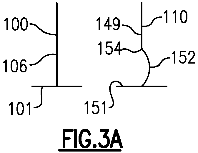
- Figure 3A shows a blade row embodiment wherein the Figure 2B blade 110 is utilized in combination with the Figure 2A blade 100.
- the vibration response will be distinct between the blades 100 and 110 and the multiplier effect will be avoided.
- the tangential shifted portion 152 is within the first 25% of span. Outwardly of points 106 and 154 the airfoils are identical. While the shifted portion is disclosed within the first 25% span, rotor blades coming under this disclosure may have a tangentially shifted portion within the first 50% of the span.
- Figure 3B shows a blade row embodiment wherein the Figure 2C blade 160 is utilized in combination with the Figure 2A blade 100.
- the vibration response will be distinct between the blades 100 and 160 and the multiplier effect will be avoided.
- the tangential shifted portion 168 is in the first 25% span, and outwardly of points 106 and 165 the airfoils are identical. While the shifted portion is disclosed within the first 25% span, rotor blade coming under this disclosure may have their tangentially shaped portion within the first 50% of the span.
- Figure 3C shows another feature.
- the embodiment blade 110 is illustrated along with the 25% span point 154 and the platform 151.
- the most shifted part 152 is shown to be shifted relative to the shape of baseline airfoil 100 by an angle A.
- the angle A is less than 2 degrees. In further embodiments, the angle A is less than 1 degree. In one embodiment, the angle A is 0.75 degrees.
- the blades 110 and 160 can be utilized to alternative from each other, rather than the baseline blade 100.
- the total tangential shift between the two blades may be above 1 degree.
- Figure 4 shows an alternative embodiment having a baseline airfoil or blade 100 having an airfoil 103 extending from a platform 101. This is the baseline airfoil such as shown at 100.
- the blades 100 are alternated with blades 210 having a platform 212, an airfoil 218 extending to top 214 and a tangentially shifted portion 216 outside the 50% span 217 of the overall airfoil 218.
- a gas turbine engine under this disclosure could be said to include a propulsor 22, a compressor section 24 and a turbine section 28, at least one of the propulsor, compressor section and turbine section having at least one row of blades mounted in a rotor.
- the plurality of blades in the at least one row each having a platform with an airfoil extending radially outwardly of the platform.
- the airfoils in a first group of said plurality of rotating blades has a different shape than the airfoils in a second group of the plurality of blades.
- a blade from the first group of blades circumferentially alternates with a blade from the second group of the plurality of blades.
- the airfoils in the second group have a portion 152/168/216 that is tangentially shifted relative to the airfoil in the first group.
- a span is defined along the airfoil between a root at the platform and a radially outer tip, and the tangentially shifted portion of the blades in the second group of the plurality of blades occurs within 50% of the span 154/165 from the root.
- the tangentially shifted portion of the blades in the second group of the plurality of blades occurs within 25% of the span.
- the airfoils in the first and second group of the plurality of blades are identical radially outwardly of the 25% span.
- the tangential shift in the airfoil of the blades in the second group has a most shifted portion which is shifted less than 2 degrees from the corresponding portion in the airfoils in the first group of the plurality of blades.
- the tangential shift in the airfoil of the blades in the second group has a most shifted portion which is shifted less than 1 degree from the corresponding portion in the airfoils in the first group of the plurality of blades.
- the at least one rotating blade row is in the compressor section.
- the at least one rotating blade row is in the turbine section.
- the airfoils in the second group has a portion 152/168/216 that is tangentially shifted relative to the airfoil in the first group.
- a span is defined along the airfoil between a root at the platform and a radially outer tip, and the tangentially shifted portion of the blades in the second group of the plurality of blades occurs within 50% of the span 154/165 from the root.
- the tangentially shifted portion of the blades in the second group of the plurality of blades occurs within 25% of the span.
- the airfoils in the first and second group of the plurality of blades are identical radially outwardly of the 25% span.
- the tangential shift in the airfoil of the blades in the second group has a most shifted portion which is shifted less than 1 degree from the corresponding portion in the airfoil in the first group of the plurality of blades.
- a span is defined along the airfoil between a root at the platform and a radially outer tip, and the different shape of the blades in the second group of the plurality of blades occurs outwardly of 50% of the span 152/165 from the root.
- the airfoils in the first group is tangentially shifted in a first direction 152
- the airfoils in the second group are tangentially shifted in an opposed second direction 168.
- the combined tangential shift between the airfoils in the first and second group is greater than 1 degree.
- the at least one rotating blade row is in the compressor section.
- the at least one rotating blade row is in the turbine section.
Landscapes
- Engineering & Computer Science (AREA)
- Mechanical Engineering (AREA)
- General Engineering & Computer Science (AREA)
- Physics & Mathematics (AREA)
- Fluid Mechanics (AREA)
- Structures Of Non-Positive Displacement Pumps (AREA)
- Chemical & Material Sciences (AREA)
- Combustion & Propulsion (AREA)
Abstract
A gas turbine engine (20) includes a propulsor (22), a compressor section (24) and a turbine section (28), at least one of the propulsor (22), compressor section (24) and turbine section (28) having at least one row of blades (100) mounted in a rotor. There are a plurality of circumferentially spaced blades (100) in the at least one row. The plurality of blades (100) in the at least one row each have a platform (101) with an airfoil (103) extending radially outwardly of the platform (101). The airfoils in a first group of said plurality of rotating blades (100) have a different shape than the airfoils in a second group of the plurality of blades.
Description
- This application relates to a method and apparatus of mistuning alternate blades in a blade row for a gas turbine engine.
- Gas turbine engines are known, and typically have a fan section delivering air into a compressor. The air is compressed and delivered into a combustor. Productions of combustion pass downstream over turbine rotors, driving them to rotate. The fan, compressor and turbine sections all have rows of rotating blades. Typically the blades in any one row are all designed to have airfoils of the same shape and size.
- Typically, a single blade shape will vibrate at a particular resonate frequency. Thus, if the blade row experiences a frequency that causes vibration, it will be multiplied across every blade in that blade row. It is desirable to avoid resonance vibrations in such components.
- A gas turbine engine includes a propulsor, a compressor section and a turbine section, at least one of the propulsor, compressor section and turbine section having at least one row of blades mounted in a rotor. There is a plurality of circumferentially spaced blades in the at least one row. The plurality of blades in the at least one row each having a platform with an airfoil extending radially outwardly of the platform. The airfoils in a first group of said plurality of rotating blades has a different shape than the airfoils in a second group of the plurality of blades.
- These and other features will be best understood from the following drawings and specification, the following is a brief description.
-
-
Figure 1 schematically shows a gas turbine engine. -
Figure 2A shows a first rotating blade shape. -
Figure 2B shows an alternative rotating blade shape. -
Figure 2C shows another alternative rotating blade shape. -
Figure 3A shows one arrangement in a blade row. -
Figure 3B shows an alternative arrangement in a blade row. -
Figure 3C shows a feature of theFigure 3A or 3B blade row. -
Figure 4 shows an alternative blade row. -
Figure 1 schematically illustrates agas turbine engine 20. The examplegas turbine engine 20 is a turbofan that generally incorporates afan section 22, acompressor section 24, acombustor section 26 and aturbine section 28. Thefan section 22 drives air along a bypass flow path B in a bypass duct defined within anacelle 30. Theturbine engine 20 intakes air along a core flow path C into thecompressor section 24 for compression and communication into thecombustor section 26. In thecombustor section 26, the compressed air is mixed with fuel from afuel system 32 and ignited byigniter 34 to generate an exhaust gas flow that expands through theturbine section 28 and is exhausted throughexhaust nozzle 36. Although depicted as a turbofan turbine engine in the disclosed non-limiting embodiment, it should be understood that the concepts described herein are not limited to use with turbofans as the teachings may be applied to other types of turbine engines. As one example, rather than having the propulsor be an enclosed fan, the propulsor may be an open propeller. This embodiment can also be applied to industrial gas turbine engine as well. -
Figure 2A shows a first blade that may be utilized in any of a fan, compressor or turbine section blade row. Ablade 100 has anairfoil 103 extending from aplatform 101 to atip 102. Theairfoil 103 merges into theplatform 101 atpoint 105. Apoint 106 may be defined at 25% of a span between thepoint 105 to thetip 102. As shown inFigure 2A , theairfoil 103 extends to be more straight through anarea including point 106 than the blades shown inFigures 2B and 2C . The area radially inward ofpoint 106 could be seen as a baseline shape. -
Figure 2B shows analternative blade 110. Blade 110 has anairfoil 149 extending from apoint 105 atplatform 151. A 25%span point 154 is illustrated. There is apoint 152 within the 25% span wherein theairfoil 149 has been shifted tangentially relative to abaseline shape 106 as found inFigure 2A . When the blades in a blade row are assembled, blades such asblade 100 andblade 110 are located to be alternating. - A worker of skill in this art would recognize that a resonant frequency will change between
blades - However, since the mis-tuning or distinct shape is found in the first 25% of span, the radially outer portions, which perform much of the aerodynamic work of the blade, are not modified. That is, outwardly of the 25%
span blades -
Figure 2C shows analternative blade 160. Here there is aplatform 162 and atip 166 and anairfoil 164 extending between the two. A 25%span point 165 defines the end of aportion 168 which is tangentially shifted relative to thebaseline 106 ofFigure 2A in an opposed direction from theFigure 2B shift. -
Figure 3A shows a blade row embodiment wherein theFigure 2B blade 110 is utilized in combination with theFigure 2A blade 100. The vibration response will be distinct between theblades portion 152 is within the first 25% of span. Outwardly ofpoints -
Figure 3B shows a blade row embodiment wherein theFigure 2C blade 160 is utilized in combination with theFigure 2A blade 100. Here again, the vibration response will be distinct between theblades portion 168 is in the first 25% span, and outwardly ofpoints -
Figure 3C shows another feature. Theembodiment blade 110 is illustrated along with the 25%span point 154 and theplatform 151. The most shiftedpart 152 is shown to be shifted relative to the shape ofbaseline airfoil 100 by an angle A. In embodiments, the angle A is less than 2 degrees. In further embodiments, the angle A is less than 1 degree. In one embodiment, the angle A is 0.75 degrees. - It is also within the scope of this invention that the
blades baseline blade 100. In such an embodiment the total tangential shift between the two blades may be above 1 degree. -
Figure 4 shows an alternative embodiment having a baseline airfoil orblade 100 having anairfoil 103 extending from aplatform 101. This is the baseline airfoil such as shown at 100. - The
blades 100 are alternated withblades 210 having a platform 212, anairfoil 218 extending to top 214 and a tangentially shiftedportion 216 outside the 50% span 217 of theoverall airfoil 218. - This arrangement will operate in a similar manner to that described above, however, the airfoils will not be identical in this arrangement outside of the 50% span point.
- A gas turbine engine under this disclosure could be said to include a
propulsor 22, acompressor section 24 and aturbine section 28, at least one of the propulsor, compressor section and turbine section having at least one row of blades mounted in a rotor. There is a plurality of circumferentially spaced blades in the at least one row. The plurality of blades in the at least one row each having a platform with an airfoil extending radially outwardly of the platform. The airfoils in a first group of said plurality of rotating blades has a different shape than the airfoils in a second group of the plurality of blades. - In another embodiment according to the previous embodiment, a blade from the first group of blades circumferentially alternates with a blade from the second group of the plurality of blades.
- In another embodiment according to any of the previous embodiments, the airfoils in the second group have a
portion 152/168/216 that is tangentially shifted relative to the airfoil in the first group. - In another embodiment according to any of the previous embodiments, a span is defined along the airfoil between a root at the platform and a radially outer tip, and the tangentially shifted portion of the blades in the second group of the plurality of blades occurs within 50% of the
span 154/165 from the root. - In another embodiment according to any of the previous embodiments, the tangentially shifted portion of the blades in the second group of the plurality of blades occurs within 25% of the span.
- In another embodiment according to any of the previous embodiments, the airfoils in the first and second group of the plurality of blades are identical radially outwardly of the 25% span.
- In another embodiment according to any of the previous embodiments, the tangential shift in the airfoil of the blades in the second group has a most shifted portion which is shifted less than 2 degrees from the corresponding portion in the airfoils in the first group of the plurality of blades.
- In another embodiment according to any of the previous embodiments, the tangential shift in the airfoil of the blades in the second group has a most shifted portion which is shifted less than 1 degree from the corresponding portion in the airfoils in the first group of the plurality of blades.
- In another embodiment according to any of the previous embodiments, the at least one rotating blade row is in the compressor section.
- In another embodiment according to any of the previous embodiments, the at least one rotating blade row is in the turbine section.
- In another embodiment according to any of the previous embodiments, the airfoils in the second group has a
portion 152/168/216 that is tangentially shifted relative to the airfoil in the first group. - In another embodiment according to any of the previous embodiments, a span is defined along the airfoil between a root at the platform and a radially outer tip, and the tangentially shifted portion of the blades in the second group of the plurality of blades occurs within 50% of the
span 154/165 from the root. - In another embodiment according to any of the previous embodiments, the tangentially shifted portion of the blades in the second group of the plurality of blades occurs within 25% of the span.
- In another embodiment according to any of the previous embodiments, the airfoils in the first and second group of the plurality of blades are identical radially outwardly of the 25% span.
- In another embodiment according to any of the previous embodiments, the tangential shift in the airfoil of the blades in the second group has a most shifted portion which is shifted less than 1 degree from the corresponding portion in the airfoil in the first group of the plurality of blades.
- In another embodiment according to any of the previous embodiments, a span is defined along the airfoil between a root at the platform and a radially outer tip, and the different shape of the blades in the second group of the plurality of blades occurs outwardly of 50% of the
span 152/165 from the root. - In another embodiment according to any of the previous embodiments, the airfoils in the first group is tangentially shifted in a
first direction 152, and the airfoils in the second group are tangentially shifted in an opposedsecond direction 168. - In another embodiment according to any of the previous embodiments, the combined tangential shift between the airfoils in the first and second group is greater than 1 degree.
- In another embodiment according to any of the previous embodiments, the at least one rotating blade row is in the compressor section.
- In another embodiment according to any of the previous embodiments, the at least one rotating blade row is in the turbine section.
- Although embodiments have been disclosed, a worker of skill in this art would recognize that modifications would come within the scope of this disclosure. For that reason, the following claims should be studied to determine the true scope and content.
Claims (13)
- A gas turbine engine (20) comprising:a propulsor (22), a compressor section (24) and a turbine section (28), at least one of the propulsor, compressor section and turbine section having at least one row of blades mounted in a rotor, there being a plurality of circumferentially spaced blades (100; 110; 160; 210) in the at least one row; andthe plurality of blades in the at least one row each having a platform (101; 151; 162; 212) with an airfoil (103; 149; 164; 218) extending radially outwardly of the platform, the airfoils in a first group of said plurality of rotating blades having a different shape than the airfoils in a second group of the plurality of blades.
- The gas turbine engine as set forth in claim 1, wherein a blade from the first group of blades circumferentially alternates with a blade from the second group of the plurality of blades.
- The gas turbine engine as set forth in claim 1 or 2, wherein the airfoils in the second group have a portion (152; 168; 216) that is tangentially shifted relative to the airfoil in the first group.
- The gas turbine engine as set forth in claim 3, wherein a span is defined along the airfoil between a root at the platform and a radially outer tip (102; 166), and the tangentially shifted portion of the blades in the second group of the plurality of blades occurs within 50% of the span from the root.
- The gas turbine engine as set forth in claim 4, wherein the tangentially shifted portion of the blades in the second group of the plurality of blades occurs within 25% of the span.
- The gas turbine engine as set forth in claim 5, wherein the airfoils in the first and second group of the plurality of blades are identical radially outwardly of the 25% span.
- The gas turbine engine as set forth in claim 6, wherein the tangential shift in the airfoil of the blades in the second group has a most shifted portion which is shifted less than 2 degrees from the corresponding portion in the airfoils in the first group of the plurality of blades.
- The gas turbine engine as set forth in claim 7, wherein the tangential shift in the airfoil of the blades in the second group has a most shifted portion which is shifted less than 1 degree from the corresponding portion in the airfoils in the first group of the plurality of blades.
- The gas turbine engine as set forth in any preceding claim, wherein a span is defined along the airfoil between a root at the platform and a radially outer tip, and the different shape of the blades in the second group of the plurality of blades occurs outwardly of 50% of the span from the root.
- The gas turbine engine as set forth in any preceding claim, wherein the airfoils in the first group is tangentially shifted in a first direction, and the airfoils in the second group are tangentially shifted in an opposed second direction.
- The gas turbine engine as set forth in claim 10, wherein the combined tangential shift between the airfoils in the first and second group is greater than 1 degree.
- The gas turbine engine as set forth in any preceding claim, wherein the at least one rotating blade row is in the compressor section.
- The gas turbine engine as set forth in any of claims 1 to 11, wherein the at least one rotating blade row is in the turbine section.
Applications Claiming Priority (1)
| Application Number | Priority Date | Filing Date | Title |
|---|---|---|---|
| US18/343,039 US20250003339A1 (en) | 2023-06-28 | 2023-06-28 | Mistuning alternate blades in a gas turbine engine |
Publications (1)
| Publication Number | Publication Date |
|---|---|
| EP4484704A1 true EP4484704A1 (en) | 2025-01-01 |
Family
ID=91738783
Family Applications (1)
| Application Number | Title | Priority Date | Filing Date |
|---|---|---|---|
| EP24185541.0A Pending EP4484704A1 (en) | 2023-06-28 | 2024-06-28 | Mistuning alternate blades in a gas turbine engine |
Country Status (3)
| Country | Link |
|---|---|
| US (1) | US20250003339A1 (en) |
| EP (1) | EP4484704A1 (en) |
| CA (1) | CA3244320A1 (en) |
Citations (7)
| Publication number | Priority date | Publication date | Assignee | Title |
|---|---|---|---|---|
| FR2944049A1 (en) * | 2009-04-02 | 2010-10-08 | Turbomeca | Compressor impeller for gas turbine of helicopter, has zone of vane of blades comprising thickness that is higher than another zone of another vane such that resonance frequency of former vane differs from latter vane resonance frequency |
| US20150110604A1 (en) * | 2012-06-14 | 2015-04-23 | Ge Avio S.R.L. | Aerofoil array for a gas turbine with anti fluttering means |
| EP2805017B1 (en) * | 2012-04-16 | 2016-06-22 | Siemens Aktiengesellschaft | Guide blade assembly for an axial flow machine and method for laying the guide blade assembly |
| US20170175776A1 (en) * | 2015-12-21 | 2017-06-22 | Pratt & Whitney Canada Corp. | Mistuned fan |
| US20180274558A1 (en) * | 2017-03-22 | 2018-09-27 | Pratt & Whitney Canada Corp. | Fan rotor with flow induced resonance control |
| US20190085868A1 (en) * | 2017-09-15 | 2019-03-21 | Pratt & Whitney Canada Corp. | Mistuned compressor rotor with hub scoops |
| US10865806B2 (en) * | 2017-09-15 | 2020-12-15 | Pratt & Whitney Canada Corp. | Mistuned rotor for gas turbine engine |
Family Cites Families (1)
| Publication number | Priority date | Publication date | Assignee | Title |
|---|---|---|---|---|
| GB2491632B (en) * | 2011-06-10 | 2013-10-30 | Rolls Royce Plc | Rotating blade analysis |
-
2023
- 2023-06-28 US US18/343,039 patent/US20250003339A1/en active Pending
-
2024
- 2024-06-25 CA CA3244320A patent/CA3244320A1/en active Pending
- 2024-06-28 EP EP24185541.0A patent/EP4484704A1/en active Pending
Patent Citations (7)
| Publication number | Priority date | Publication date | Assignee | Title |
|---|---|---|---|---|
| FR2944049A1 (en) * | 2009-04-02 | 2010-10-08 | Turbomeca | Compressor impeller for gas turbine of helicopter, has zone of vane of blades comprising thickness that is higher than another zone of another vane such that resonance frequency of former vane differs from latter vane resonance frequency |
| EP2805017B1 (en) * | 2012-04-16 | 2016-06-22 | Siemens Aktiengesellschaft | Guide blade assembly for an axial flow machine and method for laying the guide blade assembly |
| US20150110604A1 (en) * | 2012-06-14 | 2015-04-23 | Ge Avio S.R.L. | Aerofoil array for a gas turbine with anti fluttering means |
| US20170175776A1 (en) * | 2015-12-21 | 2017-06-22 | Pratt & Whitney Canada Corp. | Mistuned fan |
| US20180274558A1 (en) * | 2017-03-22 | 2018-09-27 | Pratt & Whitney Canada Corp. | Fan rotor with flow induced resonance control |
| US20190085868A1 (en) * | 2017-09-15 | 2019-03-21 | Pratt & Whitney Canada Corp. | Mistuned compressor rotor with hub scoops |
| US10865806B2 (en) * | 2017-09-15 | 2020-12-15 | Pratt & Whitney Canada Corp. | Mistuned rotor for gas turbine engine |
Also Published As
| Publication number | Publication date |
|---|---|
| US20250003339A1 (en) | 2025-01-02 |
| CA3244320A1 (en) | 2025-06-06 |
Similar Documents
| Publication | Publication Date | Title |
|---|---|---|
| EP2230382B1 (en) | Gas turbine rotor stage | |
| US10408223B2 (en) | Low hub-to-tip ratio fan for a turbofan gas turbine engine | |
| EP3431713B1 (en) | Integrally bladed rotor and corresponding gas turbine engine | |
| EP2942481B1 (en) | Rotor for a gas turbine engine | |
| US7887299B2 (en) | Rotary body for turbo machinery with mistuned blades | |
| US11353038B2 (en) | Compressor rotor for supersonic flutter and/or resonant stress mitigation | |
| EP2775119B1 (en) | Compressor shroud reverse bleed holes | |
| EP3456920B1 (en) | Mistuned rotor for gas turbine engine | |
| EP2075411A1 (en) | Integrally bladed rotor with slotted outer rim and gas turbine engine comprising such a rotor | |
| EP3379031A1 (en) | Fan rotor with flow induced resonance control | |
| US20090257877A1 (en) | Asymmetrical rotor blade fir-tree attachment | |
| US8678740B2 (en) | Turbomachine flow path having circumferentially varying outer periphery | |
| EP4311914B1 (en) | Turbine blade | |
| EP3456919A1 (en) | Rotor, corresponding gas turbine engine and method of forming a rotor | |
| CN110778367B (en) | Ribbed blade segment | |
| US20250003339A1 (en) | Mistuning alternate blades in a gas turbine engine | |
| EP2604793A2 (en) | Rotor with Internal Stiffening Ring | |
| US12410715B2 (en) | Rotor blade system for turbine engines | |
| US12385400B2 (en) | Method of manufacturing a mistuned rotor | |
| EP4219900A1 (en) | Non-uniform turbomachinery blade tips for frequency tuning | |
| US9938854B2 (en) | Gas turbine engine airfoil curvature | |
| EP4397849A1 (en) | Aircraft engine exhaust mixer | |
| CN114320481A (en) | Turbine bucket with dual part span shroud and aerodynamic features | |
| EP3190269A1 (en) | Low energy wake stage |
Legal Events
| Date | Code | Title | Description |
|---|---|---|---|
| PUAI | Public reference made under article 153(3) epc to a published international application that has entered the european phase |
Free format text: ORIGINAL CODE: 0009012 |
|
| STAA | Information on the status of an ep patent application or granted ep patent |
Free format text: STATUS: THE APPLICATION HAS BEEN PUBLISHED |
|
| AK | Designated contracting states |
Kind code of ref document: A1 Designated state(s): AL AT BE BG CH CY CZ DE DK EE ES FI FR GB GR HR HU IE IS IT LI LT LU LV MC ME MK MT NL NO PL PT RO RS SE SI SK SM TR |
|
| STAA | Information on the status of an ep patent application or granted ep patent |
Free format text: STATUS: REQUEST FOR EXAMINATION WAS MADE |
|
| 17P | Request for examination filed |
Effective date: 20250701 |