EP4484703A1 - Airfoil thickness profile for minimizing tip leakage flow - Google Patents
Airfoil thickness profile for minimizing tip leakage flow Download PDFInfo
- Publication number
- EP4484703A1 EP4484703A1 EP24184290.5A EP24184290A EP4484703A1 EP 4484703 A1 EP4484703 A1 EP 4484703A1 EP 24184290 A EP24184290 A EP 24184290A EP 4484703 A1 EP4484703 A1 EP 4484703A1
- Authority
- EP
- European Patent Office
- Prior art keywords
- thickness
- pressure side
- suction side
- side thickness
- airfoil
- Prior art date
- Legal status (The legal status is an assumption and is not a legal conclusion. Google has not performed a legal analysis and makes no representation as to the accuracy of the status listed.)
- Withdrawn
Links
Images


Classifications
-
- F—MECHANICAL ENGINEERING; LIGHTING; HEATING; WEAPONS; BLASTING
- F01—MACHINES OR ENGINES IN GENERAL; ENGINE PLANTS IN GENERAL; STEAM ENGINES
- F01D—NON-POSITIVE DISPLACEMENT MACHINES OR ENGINES, e.g. STEAM TURBINES
- F01D5/00—Blades; Blade-carrying members; Heating, heat-insulating, cooling or antivibration means on the blades or the members
- F01D5/12—Blades
- F01D5/14—Form or construction
- F01D5/141—Shape, i.e. outer, aerodynamic form
-
- F—MECHANICAL ENGINEERING; LIGHTING; HEATING; WEAPONS; BLASTING
- F01—MACHINES OR ENGINES IN GENERAL; ENGINE PLANTS IN GENERAL; STEAM ENGINES
- F01D—NON-POSITIVE DISPLACEMENT MACHINES OR ENGINES, e.g. STEAM TURBINES
- F01D5/00—Blades; Blade-carrying members; Heating, heat-insulating, cooling or antivibration means on the blades or the members
- F01D5/12—Blades
- F01D5/14—Form or construction
- F01D5/20—Specially-shaped blade tips to seal space between tips and stator
-
- F—MECHANICAL ENGINEERING; LIGHTING; HEATING; WEAPONS; BLASTING
- F01—MACHINES OR ENGINES IN GENERAL; ENGINE PLANTS IN GENERAL; STEAM ENGINES
- F01D—NON-POSITIVE DISPLACEMENT MACHINES OR ENGINES, e.g. STEAM TURBINES
- F01D11/00—Preventing or minimising internal leakage of working-fluid, e.g. between stages
- F01D11/08—Preventing or minimising internal leakage of working-fluid, e.g. between stages for sealing space between rotor blade tips and stator
-
- F—MECHANICAL ENGINEERING; LIGHTING; HEATING; WEAPONS; BLASTING
- F01—MACHINES OR ENGINES IN GENERAL; ENGINE PLANTS IN GENERAL; STEAM ENGINES
- F01D—NON-POSITIVE DISPLACEMENT MACHINES OR ENGINES, e.g. STEAM TURBINES
- F01D5/00—Blades; Blade-carrying members; Heating, heat-insulating, cooling or antivibration means on the blades or the members
- F01D5/12—Blades
- F01D5/14—Form or construction
- F01D5/141—Shape, i.e. outer, aerodynamic form
- F01D5/145—Means for influencing boundary layers or secondary circulations
-
- F—MECHANICAL ENGINEERING; LIGHTING; HEATING; WEAPONS; BLASTING
- F05—INDEXING SCHEMES RELATING TO ENGINES OR PUMPS IN VARIOUS SUBCLASSES OF CLASSES F01-F04
- F05D—INDEXING SCHEME FOR ASPECTS RELATING TO NON-POSITIVE-DISPLACEMENT MACHINES OR ENGINES, GAS-TURBINES OR JET-PROPULSION PLANTS
- F05D2240/00—Components
- F05D2240/20—Rotors
- F05D2240/24—Rotors for turbines
-
- F—MECHANICAL ENGINEERING; LIGHTING; HEATING; WEAPONS; BLASTING
- F05—INDEXING SCHEMES RELATING TO ENGINES OR PUMPS IN VARIOUS SUBCLASSES OF CLASSES F01-F04
- F05D—INDEXING SCHEME FOR ASPECTS RELATING TO NON-POSITIVE-DISPLACEMENT MACHINES OR ENGINES, GAS-TURBINES OR JET-PROPULSION PLANTS
- F05D2240/00—Components
- F05D2240/20—Rotors
- F05D2240/30—Characteristics of rotor blades, i.e. of any element transforming dynamic fluid energy to or from rotational energy and being attached to a rotor
- F05D2240/301—Cross-sectional characteristics
-
- F—MECHANICAL ENGINEERING; LIGHTING; HEATING; WEAPONS; BLASTING
- F05—INDEXING SCHEMES RELATING TO ENGINES OR PUMPS IN VARIOUS SUBCLASSES OF CLASSES F01-F04
- F05D—INDEXING SCHEME FOR ASPECTS RELATING TO NON-POSITIVE-DISPLACEMENT MACHINES OR ENGINES, GAS-TURBINES OR JET-PROPULSION PLANTS
- F05D2240/00—Components
- F05D2240/20—Rotors
- F05D2240/30—Characteristics of rotor blades, i.e. of any element transforming dynamic fluid energy to or from rotational energy and being attached to a rotor
- F05D2240/306—Characteristics of rotor blades, i.e. of any element transforming dynamic fluid energy to or from rotational energy and being attached to a rotor related to the suction side of a rotor blade
-
- F—MECHANICAL ENGINEERING; LIGHTING; HEATING; WEAPONS; BLASTING
- F05—INDEXING SCHEMES RELATING TO ENGINES OR PUMPS IN VARIOUS SUBCLASSES OF CLASSES F01-F04
- F05D—INDEXING SCHEME FOR ASPECTS RELATING TO NON-POSITIVE-DISPLACEMENT MACHINES OR ENGINES, GAS-TURBINES OR JET-PROPULSION PLANTS
- F05D2240/00—Components
- F05D2240/20—Rotors
- F05D2240/30—Characteristics of rotor blades, i.e. of any element transforming dynamic fluid energy to or from rotational energy and being attached to a rotor
- F05D2240/307—Characteristics of rotor blades, i.e. of any element transforming dynamic fluid energy to or from rotational energy and being attached to a rotor related to the tip of a rotor blade
-
- F—MECHANICAL ENGINEERING; LIGHTING; HEATING; WEAPONS; BLASTING
- F05—INDEXING SCHEMES RELATING TO ENGINES OR PUMPS IN VARIOUS SUBCLASSES OF CLASSES F01-F04
- F05D—INDEXING SCHEME FOR ASPECTS RELATING TO NON-POSITIVE-DISPLACEMENT MACHINES OR ENGINES, GAS-TURBINES OR JET-PROPULSION PLANTS
- F05D2250/00—Geometry
- F05D2250/70—Shape
- F05D2250/71—Shape curved
- F05D2250/713—Shape curved inflexed
Definitions
- the present disclosure relates generally to a rotating airfoil utilized in a turbine engine. More particularly, this disclosure relates to an airfoil for reducing leakage flow between a tip of the rotating airfoil and a static structure.
- a gas turbine engine typically includes a fan section, a compressor section, a combustor section and a turbine section.
- the compressor and turbine sections include rotating blades within a case structure.
- a clearance between tips of the rotating blades and the case structure is a source of leakage flow that decreases engine efficiency. Leakage flow is driven by a pressure differential across the tip.
- the clearance between tips of the rotating blades can be minimized but some minimal clearance is required to accommodate relative movement during operation.
- the rotating blades are sized with a minimum thickness for durability and to provide desired airflow characteristics. Blade efficiency is improved by reducing leakage flow.
- a turbine engine assembly includes at least one rotor that has a plurality of blades, each of the blades includes an airfoil that has a pressure side and a suction side that each extend between a leading edge, a trailing edge, a tip and a base.
- the airfoil has a thickness between the pressure side and the suction side perpendicular to a camber line that varies between the leading edge and the trailing edge.
- the thickness includes a suction side thickness between the camber line and the suction side and a pressure side thickness between the camber line and the pressure side.
- a maximum ratio of the pressure side thickness to the suction side thickness is between 3 and 7.
- the maximum ratio of the pressure side thickness to the suction side thickness is disposed between 80% and 100% of a height of the airfoil between the base and the tip portion.
- the maximum ratio of the pressure side thickness to the suction side thickness is at a location between 5% and 40% of a meridional length between the leading edge and the trailing edge.
- the maximum ratio of the pressure side thickness to the suction side thickness is at a location between 10% and 30% of a meridional length between the leading edge and the trailing edge.
- the maximum ratio of the pressure side thickness to the suction side thickness is between 5 and 7.
- the maximum ratio of the pressure side thickness to the suction side thickness is 6.
- the at least one rotor includes a turbine rotor 38.
- the maximum ratio of the pressure side thickness 60 to the suction side thickness 62 is between 5 and 7.
- a method of forming a blade utilized in a turbine engine assembly includes forming an airfoil 42 of the blade assembly to include a thickness between pressure side 52 and a suction side 54 that is perpendicular to a camber line 56 that includes a suction side thickness 62 between the camber line 56 and the suction side 54 and a pressure side thickness 60 between the camber line 56 and the pressure side 52 such that a maximum ratio of the pressure side thickness 60 to the suction side thickness 62 is between 3 and 7.
- the method further includes locating the maximum ratio of the pressure side thickness 60 to the suction side 54 thickness within a location between 80% and 100% of a height of the airfoil 42 between a base 50 and a tip portion.
- the method further includes locating the maximum ratio of the pressure side thickness 60 to the suction side thickness 62 within a location between 5% and 40% of a meridional length 66 between a leading edge 44 and a trailing edge 46.
- the maximum ratio of the pressure side thickness 60 to the suction side thickness 62 is between 5 and 7 and is within a location between 15% and 25% of the meridional length 66 between a leading edge 44 and a trailing edge 46.
Landscapes
- Engineering & Computer Science (AREA)
- Mechanical Engineering (AREA)
- General Engineering & Computer Science (AREA)
- Physics & Mathematics (AREA)
- Fluid Mechanics (AREA)
- Turbine Rotor Nozzle Sealing (AREA)
- Structures Of Non-Positive Displacement Pumps (AREA)
Abstract
A turbine engine assembly includes at least one rotor (34, 38) that has a plurality of blades (36), each of the blades (36) includes an airfoil (42) that has a pressure side (52) and a suction side (54) that each extend between a leading edge (44), a trailing edge (46), a tip (48) and a base (50). The airfoil (42) has a thickness (58) between the pressure side (52) and the suction side (54) perpendicular to a (56) camber line that varies between the leading edge (44) and the trailing edge (46). The thickness (58) includes a suction side thickness (62) between the camber line (56) and the suction side (54) and a pressure side thickness (60) between the camber line (56) and the pressure side (52). A maximum ratio (80) of the pressure side thickness (60) to the suction side thickness (62) is between 3 and 7.
Description
- The present disclosure relates generally to a rotating airfoil utilized in a turbine engine. More particularly, this disclosure relates to an airfoil for reducing leakage flow between a tip of the rotating airfoil and a static structure.
- A gas turbine engine typically includes a fan section, a compressor section, a combustor section and a turbine section. The compressor and turbine sections include rotating blades within a case structure. A clearance between tips of the rotating blades and the case structure is a source of leakage flow that decreases engine efficiency. Leakage flow is driven by a pressure differential across the tip. The clearance between tips of the rotating blades can be minimized but some minimal clearance is required to accommodate relative movement during operation. Moreover, the rotating blades are sized with a minimum thickness for durability and to provide desired airflow characteristics. Blade efficiency is improved by reducing leakage flow.
- A turbine engine assembly according to an aspect of the present invention, among other possible things includes at least one rotor that has a plurality of blades, each of the blades includes an airfoil that has a pressure side and a suction side that each extend between a leading edge, a trailing edge, a tip and a base. The airfoil has a thickness between the pressure side and the suction side perpendicular to a camber line that varies between the leading edge and the trailing edge. The thickness includes a suction side thickness between the camber line and the suction side and a pressure side thickness between the camber line and the pressure side. A maximum ratio of the pressure side thickness to the suction side thickness is between 3 and 7.
- In an embodiment of the above, the maximum ratio of the pressure side thickness to the suction side thickness is disposed between 80% and 100% of a height of the airfoil between the base and the tip portion.
- In an embodiment according to any of the previous embodiments, the maximum ratio of the pressure side thickness to the suction side thickness is at a location between 5% and 40% of a meridional length between the leading edge and the trailing edge.
- In an embodiment according to any of the previous embodiments, the maximum ratio of the pressure side thickness to the suction side thickness is at a location between 10% and 30% of a meridional length between the leading edge and the trailing edge.
- In an embodiment according to any of the previous embodiments, the maximum ratio of the pressure side thickness to the suction side thickness is between 5 and 7.
- In an embodiment according to any of the previous embodiments, the maximum ratio of the pressure side thickness to the suction side thickness is 6.
- In an embodiment according to any of the previous embodiments, the maximum ratio of the pressure side thickness to the suction side thickness is at a location that is between 15% and 25% of the meridional length between the leading edge and the trailing edge.
- In an embodiment according to any of the previous embodiments, the at least one rotor comprises a compressor rotor.
- In an embodiment according to any of the previous embodiments, the at least one rotor comprises a turbine rotor.
- A blade for compressor section of a turbine engine assembly according to another aspect of the present invention, among other possible things includes an airfoil that has a pressure side and a suction side that each extend between a leading edge, a trailing edge, a tip and a base. The airfoil has a thickness between the pressure side and the suction side perpendicular to a camber line that varies between the leading edge and the trailing edge. The thickness includes a suction side thickness between the camber line and the suction side and a pressure side thickness between the camber line and the pressure side. A maximum ratio of the pressure side thickness to the suction side thickness is between 3 and 7.
- In an embodiment of the above, the ratio of the pressure side thickness to the suction side thickness is disposed between 80% and 100% of a height of the airfoil between the base and the tip portion.
- In an embodiment according to any of the previous embodiments, the maximum ratio of the pressure side thickness to the suction side thickness is at a location between 5% and 40% of a meridional length between the leading edge and the trailing edge.
- In an embodiment according to any of the previous embodiments, the maximum ratio of the pressure side thickness to the suction side thickness is at a location between 10% and 30% of a meridional length between the leading edge and the trailing edge.
- In an embodiment according to any of the previous embodiments, the maximum ratio of the pressure side thickness to the suction side thickness is between 5 and 7.
- In an embodiment according to any of the previous embodiments, the maximum ratio of the pressure side thickness to the suction side thickness is 6.
- In an embodiment according to any of the previous embodiments, the maximum ratio of the pressure side thickness to the suction side thickness is at a location that is between 15% and 25% of the meridional length between the leading edge and the trailing edge.
- A method of forming a blade utilized in a turbine engine assembly, the method, according to another aspect of the present invention, among other possible things includes forming an airfoil of the blade assembly to include a thickness between pressure side and a suction side that is perpendicular to a camber line that includes a suction side thickness between the camber line and the suction side and a pressure side thickness between the camber line and the pressure side such that a maximum ratio of the pressure side thickness to the suction side thickness is between 3 and 7.
- In an embodiment of the above, the method further comprises locating the maximum ratio of the pressure side thickness to the suction side thickness within a location between 80% and 100% of a height of the airfoil between a base and a tip portion.
- In an embodiment of the above, the method further comprises locating the maximum ratio of the pressure side thickness to the suction side thickness within a location between 5% and 40% of a meridional length between a leading edge and a trailing edge.
- In an embodiment of the above, the maximum ratio of the pressure side thickness to the suction side thickness is between 5 and 7 and is within a location between 15% and 25% of the meridional length between a leading edge and a trailing edge.
- Although the different examples have the specific components shown in the illustrations, embodiments of this disclosure are not limited to those particular combinations. It is possible to use some of the components or features from one of the examples in combination with features or components from another one of the examples.
- These and other features disclosed herein can be best understood from the following specification and drawings, the following of which is a brief description.
-
-
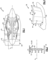
Figure 1 is a schematic view of an example gas turbine engine. -
Figure 2 is a schematic view of an example rotor embodiment. -
Figure 3 is a schematic view of an example blade embodiment. -
Figure 4 is a schematic cross-sectional view of an example airfoil embodiment. -
Figure 5 is a schematic view of an example airfoil embodiment. -
Figure 6 is a graph illustrating an example thickness ratio profile of an example airfoil embodiment. -
Figure 1 schematically illustrates agas turbine engine 20. The disclosedgas turbine engine 20 includes airfoils with a defined thickness profile that provides a reduction in a pressure difference across an airfoil tip between pressure and suction sides of the airfoil. The airfoil thickness profile is asymmetric about a camber line that provides a shape that minimizes the pressure difference across the tip. Reduction in the pressure difference across the airfoil tip between the pressure and suction sides of the airfoil provides a reduction in leakage flows. - The example
gas turbine engine 20 is a turbofan that generally incorporates afan section 22, a compressor section 24, acombustor section 26 and aturbine section 28. Thefan section 22 drives air along a bypass flow path B in a bypass duct defined within anacelle 30. The compressor section 24 drives air along a core flow path C into the compressor section 24 for compression and communication into thecombustor section 26. In thecombustor section 26, the compressed air is mixed with fuel from a fuel system 32 and burnt to generate an exhaust gas flow that expands through theturbine section 28 to generate mechanical power utilized to drive thefan section 22 and thecompressor section 26. - Although depicted as a turbofan turbine engine in the disclosed non-limiting embodiment, it should be understood that the concepts described herein are not limited to use with turbofans as the teachings may be applied to other types of gas turbine engines.
- The compressor section 24 includes at least one
compressor rotor 34 and theturbine section 26 includes at least oneturbine rotor 38. Therotors - Referring to
Figures 2 and 3 with continued reference toFigure 1 , therotors blades 36 supported on ahub structure 40. Theexample blades 36 may be compressor blades or turbine blades and are shown schematically by way of example. Theblades 36 rotate relative to a fixed case structure that is shown schematically at 70. A leakage flow 74 moves through aclearance gap 72 between a tip of theblade 36 and thecase structure 70. - Each of the
blades 36 include anairfoil 42 with apressure side 52 and asuction side 54. Each side of theairfoil 42 extends between aleading edge 44, a trailingedge 46, abase 50 and atip 48. - Referring to
Figure 4 with continued reference toFigures 2 and 3 , a cross-section of anexample airfoil 36 is shown and illustrates acamber line 56 that extends from the leadingedge 44 to the trailingedge 46. Theairfoil 42 has athickness 58 that is measured perpendicular to thecamber line 56. Thethickness 58 between thepressure side 52 and thesuction side 54 varies along thecamber line 56 between theleading edge 44 and the trailingedge 46. - The
thickness 58 is a total thickness across theairfoil 42 and is formed from apressure side thickness 60 and asuction side thickness 62. Thepressure side thickness 60 is disposed perpendicular to thecamber line 56 between thecamber line 56 and thepressure side 52. Thesuction side thickness 62 is disposed perpendicular to thecamber line 56 between thecamber line 56 and thesuction side 54. - The
example airfoil 42 includes a thickness profile along thecamber line 56 where thepressure side thickness 60 is greater than thesuction side thickness 62. The largerpressure side thickness 60 provides for a bias of theairfoil thickness 58 toward thepressure side 52. The biased thickness toward thepressure side 52 generates a bump that provides localized increases in flow velocity that reduce pressure on thepressure side 52. Reducing pressure on thepressure side 52 provides a reduction in the pressure differential between thepressure side 52 and thesuction side 54. The reduced pressure difference provides a reduction in leakage flow 74 without changing theclearance gap 72. - Referring to
Figures 5 and6 with continued reference toFigure 4 , anexample airfoil 42 embodiment includes athickness profile 78 defined as athickness ratio 80 between thepressure side thickness 60 and thesuction side thickness 62 as shown in thegraph 76 ofFigure 6 . - In one example embodiment, the
example thickness profile 78 is disposed along the airfoil within atip region 82 as schematically shown inFigure 5 . In one example embodiment, thetip region 82 is disposed between 80% and 100% of theairfoil height 64. Although theexample thickness profile 78 is disclosed as being located within thetip region 82, thethickness profile 78 may be located throughout theairfoil height 64 and remain within the contemplation of this disclosure. - The
thickness profile 78 illustrates variations in the ratio of thepressure side thickness 60 to thesuction side thickness 62 for locations along themeridional length 66. In one example embodiment, thethickness ratio 80 of thepressure side thickness 62 to the suction side thickness is greatest within themeridional length 66 between 5% and 40%. In another example embodiment, thethickness ratio 80 is greatest within a meridional length between 10% and 30%. In another disclosed example embodiment, thethickness ratio 80 is greatest between 15% and 25% of themeridional length 66. In another disclosed example embodiment, thethickness ratio 80 is greatest at 20% of themeridional length 66. - The
thickness ratio 80 reflects the increase in thepressure side thickness 60 compared to thesuction side thickness 62. Theexample thickness profile 78 is shown with upper and lower limits centered along a mean thickness ratio. In one example embodiment, thethickness ratio 80 varies between 3 and 7 along themeridional length 66. In another example embodiment, amaximum thickness ratio 84 is between 5 and 7. In other words, thepressure side thickness 60 is between 5 and 7 times larger than thesuction side thickness 62. In another example embodiment, themaximum thickness ratio 84 is 6. - The
example thickness ratio 80 may vary along themeridional length 66 but maintains theoverall thickness 58. Maintaining theoverall thickness 58 does not change the physical properties of theairfoil 42 and thereby maintains the defined mechanical structural properties. Because theairfoils thickness 58 remains unchanged, airfoils structural integrity is not compromised nor changed. Moreover, maintaining the sameoverall thickness 58 of theairfoil 42 has minimal impact on cost and/or manufacture. - A
turbine engine assembly 20 according to an exemplary embodiment of this disclosure, among other possible things includes at least one rotor that has a plurality ofblades 36, each of theblades 36 includes anairfoil 42 that has apressure side 52 and asuction side 54 that each extend between aleading edge 44, a trailingedge 46, atip 48 and abase 50. Theairfoil 42 has a thickness between thepressure side 52 and thesuction side 54 perpendicular to acamber line 56 that varies between theleading edge 44 and the trailingedge 46. The thickness includes asuction side thickness 62 between thecamber line 56 and thesuction side 54 and apressure side thickness 60 between thecamber line 56 and thepressure side 52. A maximum ratio of thepressure side thickness 60 to thesuction side thickness 62 is between 3 and 7. - In a further embodiment of the foregoing turbine engine assembly, the maximum ratio of the
pressure side thickness 60 to thesuction side thickness 62 is disposed between 80% and 100% of a height of theairfoil 42 between the base 50 and the tip portion. - In a further embodiment of any of the foregoing turbine engine assemblies, the maximum ratio of the
pressure side thickness 60 to thesuction side thickness 62 is at a location between 5% and 40% of ameridional length 66 between theleading edge 44 and the trailingedge 46. - In a further embodiment of any of the foregoing turbine engine assemblies, the maximum ratio of the
pressure side thickness 60 to thesuction side thickness 62 is at a location between 10% and 30% of ameridional length 66 between theleading edge 44 and the trailingedge 46. - In a further embodiment of any of the foregoing turbine engine assemblies, the maximum ratio of the
pressure side thickness 60 to thesuction side thickness 62 is between 5 and 7. - In a further embodiment of any of the foregoing turbine engine assemblies, the maximum ratio of the
pressure side thickness 60 to thesuction side thickness 62 is 6. - In a further embodiment of any of the foregoing turbine engine assemblies, the maximum ratio of the
pressure side thickness 60 to thesuction side thickness 62 is at a location that is between 15% and 25% of themeridional length 66 between theleading edge 44 and the trailingedge 46. - In a further embodiment of any of the foregoing turbine engine assemblies, the at least one rotor includes a
compressor rotor 34. - In a further embodiment of any of the foregoing turbine engine assemblies, the at least one rotor includes a
turbine rotor 38. - A
blade 36 for compressor section of a turbine engine assembly according to another exemplary embodiment of this disclosure, among other possible things includes anairfoil 42 that has apressure side 52 and asuction side 54 that each extend between aleading edge 44, a trailingedge 46, atip 48 and abase 50. Theairfoil 42 has a thickness between thepressure side 52 and thesuction side 54 perpendicular to acamber line 56 that varies between theleading edge 44 and the trailingedge 46. The thickness includes asuction side thickness 62 between thecamber line 56 and thesuction side 54 and apressure side thickness 60 between thecamber line 56 and thepressure side 52. A maximum ratio of thepressure side thickness 60 to thesuction side thickness 62 is between 3 and 7. - In a further embodiment of the foregoing blade, the ratio of the
pressure side thickness 60 to thesuction side thickness 62 is disposed between 80% and 100% of a height of theairfoil 42 between the base 50 and the tip portion. - In a further embodiment of any of the foregoing blades, the maximum ratio of the
pressure side thickness 60 to thesuction side thickness 62 is at a location between 5% and 40% of ameridional length 66 between theleading edge 44 and the trailingedge 46. - In a further embodiment of any of the foregoing blades, the maximum ratio of the
pressure side thickness 60 to thesuction side thickness 62 is at a location between 10% and 30% of ameridional length 66 between theleading edge 44 and the trailingedge 46. - In a further embodiment of any of the foregoing blades, the maximum ratio of the
pressure side thickness 60 to thesuction side thickness 62 is between 5 and 7. - In a further embodiment of any of the foregoing blades, the maximum ratio of the
pressure side thickness 60 to thesuction side thickness 62 is 6. - In a further embodiment of any of the foregoing blades, the maximum ratio of the
pressure side thickness 60 to thesuction side thickness 62 is at a location that is between 15% and 25% of themeridional length 66 between theleading edge 44 and the trailingedge 46. - A method of forming a blade utilized in a turbine engine assembly, the method, according to another exemplary embodiment of this disclosure, among other possible things includes forming an
airfoil 42 of the blade assembly to include a thickness betweenpressure side 52 and asuction side 54 that is perpendicular to acamber line 56 that includes asuction side thickness 62 between thecamber line 56 and thesuction side 54 and apressure side thickness 60 between thecamber line 56 and thepressure side 52 such that a maximum ratio of thepressure side thickness 60 to thesuction side thickness 62 is between 3 and 7. - In a further embodiment of the foregoing, the method further includes locating the maximum ratio of the
pressure side thickness 60 to thesuction side 54 thickness within a location between 80% and 100% of a height of theairfoil 42 between a base 50 and a tip portion. - In a further embodiment of any of the foregoing, the method further includes locating the maximum ratio of the
pressure side thickness 60 to thesuction side thickness 62 within a location between 5% and 40% of ameridional length 66 between aleading edge 44 and a trailingedge 46. - In a further embodiment of any of the foregoing methods, the maximum ratio of the
pressure side thickness 60 to thesuction side thickness 62 is between 5 and 7 and is within a location between 15% and 25% of themeridional length 66 between aleading edge 44 and a trailingedge 46. - Although an example embodiment has been disclosed, a worker of ordinary skill in this art would recognize that certain modifications would come within the scope of this disclosure. For that reason, the following claims should be studied to determine the scope and content of this disclosure.
Claims (14)
- A turbine engine assembly comprising:at least one rotor (34, 38) having a plurality of blades (36), wherein each of the blades (36) include;an airfoil (42) having;a pressure side (52) and a suction side (54) that each extend between a leading edge (44), a trailing edge (46), a tip (48) and a base (50); anda thickness (58) between the pressure side (52) and the suction side (54) perpendicular to a camber line (56) that varies between the leading edge (44) and the trailing edge (46), wherein the thickness (58) comprises a suction side thickness (62) between the camber line (56) and the suction side (54) and a pressure side thickness (60) between the camber line (56) and the pressure side (52), wherein a maximum ratio (80) of the pressure side thickness (60) to the suction side thickness (62) is between 3 and 7.
- The turbine engine assembly as recited in claim 1, wherein the at least one rotor (34, 38) comprises a compressor rotor (34).
- The turbine engine assembly as recited in claim 1 or 2, wherein the at least one rotor (34, 38) comprises a turbine rotor (38).
- A blade for compressor section of a turbine engine assembly comprising:
an airfoil (42) having a pressure side (52) and a suction side (54) that each extend between a leading edge (44), a trailing edge (46), a tip (48) and a base (50), the airfoil (42) having a thickness (58) between the pressure side (52) and the suction side (54) perpendicular to a camber line (56) that varies between the leading edge (44) and the trailing edge (46), wherein the thickness (58) comprises a suction side thickness (62) between the camber line (56) and the suction side (54) and a pressure side thickness (60) between the camber line (56) and the pressure side (52), wherein a maximum ratio (80) of the pressure side thickness (60) to the suction side thickness (62) is between 3 and 7. - The turbine engine assembly or blade as recited in any preceding claim, wherein the maximum ratio (80) of the pressure side thickness (60) to the suction side thickness (62) is disposed between 80% and 100% of a height of the airfoil (42) between the base (50) and the tip (48).
- The turbine engine assembly or blade as recited in any preceding claim, wherein the maximum ratio (80) of the pressure side thickness (60) to the suction side thickness (62) is at a location between 5% and 40% of a meridional length (66) between the leading edge (44) and the trailing edge (46).
- The turbine engine assembly or blade as recited in claim 6, wherein the maximum ratio (80) of the pressure side thickness (60) to the suction side thickness (62) is at a location between 10% and 30% of a meridional length (66) between the leading edge (44) and the trailing edge (46).
- The turbine engine assembly or blade as recited in claim 7, wherein the maximum ratio (80) of the pressure side thickness (60) to the suction side thickness (62) is at a location that is between 15% and 25% of the meridional length (66) between the leading edge (44) and the trailing edge (46).
- The turbine engine assembly or blade as recited in any preceding claim, wherein the maximum ratio (80) of the pressure side thickness (60) to the suction side thickness (62) is between 5 and 7.
- The turbine engine assembly or blade as recited in claim 9, wherein the maximum ratio (80) of the pressure side thickness (60) to the suction side thickness (62) is 6.
- A method of forming a blade utilized in a turbine engine assembly, the method comprising:forming an airfoil (42) of the blade assembly to include a thickness (58) between a pressure side (52) and a suction side (54) that is perpendicular to a camber line (56) includes a suction side thickness (62) between the camber line (56) and the suction side (54) and a pressure side thickness (60) between the camber line (56) and the pressure side (52) such that a maximum ratio (80) of the pressure side thickness (60) to the suction side thickness (62) is between 3 and 7.
- The method as recited in claim 11, further comprising locating the maximum ratio (80) of the pressure side thickness (60) to the suction side thickness (62) within a location between 80% and 100% of a height of the airfoil (42) between a base (50) and a tip (48).
- The method as recited in claim 11 or 12, further comprising locating the maximum ratio (80) of the pressure side thickness (60) to the suction side thickness (62) within a location between 5% and 40% of a meridional length (66) between a leading edge (44) and a trailing edge (46).
- The method as recited in any of claims 11 to 13, wherein the maximum ratio (80) of the pressure side thickness (60) to the suction side thickness (62) is between 5 and 7 and is within a location between 15% and 25% of the meridional length (66) between a leading edge (44) and a trailing edge (46).
Applications Claiming Priority (1)
| Application Number | Priority Date | Filing Date | Title |
|---|---|---|---|
| US18/341,220 US12410714B2 (en) | 2023-06-26 | 2023-06-26 | Airfoil thickness profile for minimizing tip leakage flow |
Publications (1)
| Publication Number | Publication Date |
|---|---|
| EP4484703A1 true EP4484703A1 (en) | 2025-01-01 |
Family
ID=91670568
Family Applications (1)
| Application Number | Title | Priority Date | Filing Date |
|---|---|---|---|
| EP24184290.5A Withdrawn EP4484703A1 (en) | 2023-06-26 | 2024-06-25 | Airfoil thickness profile for minimizing tip leakage flow |
Country Status (3)
| Country | Link |
|---|---|
| US (1) | US12410714B2 (en) |
| EP (1) | EP4484703A1 (en) |
| CA (1) | CA3244145A1 (en) |
Citations (4)
| Publication number | Priority date | Publication date | Assignee | Title |
|---|---|---|---|---|
| US20110097210A1 (en) * | 2009-10-23 | 2011-04-28 | General Electric Company | Turbine airfoil |
| DE102012021400A1 (en) * | 2012-10-31 | 2014-04-30 | Rolls-Royce Deutschland Ltd & Co Kg | Turbine rotor blade of gas turbine engine, has overhang which is provided at stagnation point, when intersection point is zero, so that maximum value of barrel length of suction-side overhang is at about specific percentage |
| US20150104296A1 (en) * | 2012-02-29 | 2015-04-16 | Mitsubishi Heavy Industries, Ltd. | Variable geometry turbocharger |
| EP2987956A1 (en) * | 2014-08-18 | 2016-02-24 | Siemens Aktiengesellschaft | Compressor aerofoil |
Family Cites Families (13)
| Publication number | Priority date | Publication date | Assignee | Title |
|---|---|---|---|---|
| US5395071A (en) * | 1993-09-09 | 1995-03-07 | Felix; Frederick L. | Airfoil with bicambered surface |
| DE19913269A1 (en) * | 1999-03-24 | 2000-09-28 | Asea Brown Boveri | Turbine blade |
| US6905309B2 (en) * | 2003-08-28 | 2005-06-14 | General Electric Company | Methods and apparatus for reducing vibrations induced to compressor airfoils |
| US8206108B2 (en) | 2007-12-10 | 2012-06-26 | Honeywell International Inc. | Turbine blades and methods of manufacturing |
| DE102009036406A1 (en) * | 2009-08-06 | 2011-02-10 | Mtu Aero Engines Gmbh | airfoil |
| US10006297B2 (en) * | 2013-02-21 | 2018-06-26 | Mitsubishi Heavy Industries, Ltd. | Turbine rotor blade |
| US20160024930A1 (en) * | 2014-07-24 | 2016-01-28 | General Electric Company | Turbomachine airfoil |
| US9879539B2 (en) * | 2014-11-18 | 2018-01-30 | Honeywell International Inc. | Engine airfoils and methods for reducing airfoil flutter |
| US10001014B2 (en) | 2016-02-09 | 2018-06-19 | General Electric Company | Turbine bucket profile |
| EP3477059A1 (en) | 2017-10-26 | 2019-05-01 | Siemens Aktiengesellschaft | Compressor aerofoil |
| CN110287647B (en) | 2019-07-18 | 2022-10-21 | 大连海事大学 | A Design Method for Shock Wave Control of Planar Cascades of Transonic Compressors |
| CN112069630B (en) | 2020-11-11 | 2021-01-22 | 中国航发上海商用航空发动机制造有限责任公司 | Compressor, blade, two-dimensional blade profile design method of blade and computer equipment |
| US11371359B2 (en) | 2020-11-26 | 2022-06-28 | Pratt & Whitney Canada Corp. | Turbine blade for a gas turbine engine |
-
2023
- 2023-06-26 US US18/341,220 patent/US12410714B2/en active Active
-
2024
- 2024-06-21 CA CA3244145A patent/CA3244145A1/en active Pending
- 2024-06-25 EP EP24184290.5A patent/EP4484703A1/en not_active Withdrawn
Patent Citations (4)
| Publication number | Priority date | Publication date | Assignee | Title |
|---|---|---|---|---|
| US20110097210A1 (en) * | 2009-10-23 | 2011-04-28 | General Electric Company | Turbine airfoil |
| US20150104296A1 (en) * | 2012-02-29 | 2015-04-16 | Mitsubishi Heavy Industries, Ltd. | Variable geometry turbocharger |
| DE102012021400A1 (en) * | 2012-10-31 | 2014-04-30 | Rolls-Royce Deutschland Ltd & Co Kg | Turbine rotor blade of gas turbine engine, has overhang which is provided at stagnation point, when intersection point is zero, so that maximum value of barrel length of suction-side overhang is at about specific percentage |
| EP2987956A1 (en) * | 2014-08-18 | 2016-02-24 | Siemens Aktiengesellschaft | Compressor aerofoil |
Also Published As
| Publication number | Publication date |
|---|---|
| US20240426218A1 (en) | 2024-12-26 |
| US12410714B2 (en) | 2025-09-09 |
| CA3244145A1 (en) | 2025-06-06 |
Similar Documents
| Publication | Publication Date | Title |
|---|---|---|
| JP3789131B2 (en) | Rotor blade with controlled tip leakage flow | |
| US10018050B2 (en) | Turbomachine rotor blade | |
| EP3378780B1 (en) | Boundary layer ingestion engine with integrally bladed fan disk | |
| US20200248566A1 (en) | Feather seals with leakage metering | |
| EP1942252B1 (en) | Airfoil tip for a rotor assembly | |
| EP0942150A2 (en) | A stator vane assembly for a turbomachine | |
| US20180252113A1 (en) | Gas turbine engine vanes | |
| US9297259B2 (en) | Compressor blade | |
| EP3208467A1 (en) | Compressor rotor for supersonic flutter and/or resonant stress mitigation | |
| EP3150803A1 (en) | Airfoil and method of cooling | |
| US11473434B2 (en) | Gas turbine engine airfoil | |
| EP3919724B1 (en) | Characteristic distribution for rotor blade of booster rotor | |
| US9175574B2 (en) | Guide vane with a winglet for an energy converting machine and machine for converting energy comprising the guide vane | |
| US10385865B2 (en) | Airfoil tip geometry to reduce blade wear in gas turbine engines | |
| US20180230821A1 (en) | Turbine blade having a tip shroud | |
| US7293964B2 (en) | Repair method for a blade of a turbomachine | |
| EP3919722A1 (en) | Characteristic distribution for rotor blade of booster rotor | |
| EP3919723A1 (en) | Characteristic distribution for rotor blade of booster rotor | |
| US12410714B2 (en) | Airfoil thickness profile for minimizing tip leakage flow | |
| US11634988B2 (en) | Turbomachine blade having a maximum thickness law with high flutter margin | |
| EP3686397B1 (en) | Stacking of rotor blade aerofoil sections to adjust resonant frequencies | |
| CN114320481B (en) | Turbine blade with dual part span shroud and aerodynamic feature | |
| EP4733549A1 (en) | Booster rotors and methods of operating gas turbine engines | |
| EP4553285A1 (en) | Turbine engine with a blade assembly having cooling holes | |
| EP3333365A1 (en) | Stator with support structure feature for tuned airfoil |
Legal Events
| Date | Code | Title | Description |
|---|---|---|---|
| PUAI | Public reference made under article 153(3) epc to a published international application that has entered the european phase |
Free format text: ORIGINAL CODE: 0009012 |
|
| STAA | Information on the status of an ep patent application or granted ep patent |
Free format text: STATUS: THE APPLICATION HAS BEEN PUBLISHED |
|
| AK | Designated contracting states |
Kind code of ref document: A1 Designated state(s): AL AT BE BG CH CY CZ DE DK EE ES FI FR GB GR HR HU IE IS IT LI LT LU LV MC ME MK MT NL NO PL PT RO RS SE SI SK SM TR |
|
| STAA | Information on the status of an ep patent application or granted ep patent |
Free format text: STATUS: THE APPLICATION IS DEEMED TO BE WITHDRAWN |
|
| 18D | Application deemed to be withdrawn |
Effective date: 20250702 |