EP4484656A2 - Working machine - Google Patents
Working machine Download PDFInfo
- Publication number
- EP4484656A2 EP4484656A2 EP24182108.1A EP24182108A EP4484656A2 EP 4484656 A2 EP4484656 A2 EP 4484656A2 EP 24182108 A EP24182108 A EP 24182108A EP 4484656 A2 EP4484656 A2 EP 4484656A2
- Authority
- EP
- European Patent Office
- Prior art keywords
- operator
- console
- seat
- wall portion
- machine body
- Prior art date
- Legal status (The legal status is an assumption and is not a legal conclusion. Google has not performed a legal analysis and makes no representation as to the accuracy of the status listed.)
- Pending
Links
Images








Classifications
-
- E—FIXED CONSTRUCTIONS
- E02—HYDRAULIC ENGINEERING; FOUNDATIONS; SOIL SHIFTING
- E02F—DREDGING; SOIL-SHIFTING
- E02F9/00—Component parts of dredgers or soil-shifting machines, not restricted to one of the kinds covered by groups E02F3/00 - E02F7/00
- E02F9/16—Cabins, platforms, or the like, for drivers
-
- E—FIXED CONSTRUCTIONS
- E02—HYDRAULIC ENGINEERING; FOUNDATIONS; SOIL SHIFTING
- E02F—DREDGING; SOIL-SHIFTING
- E02F9/00—Component parts of dredgers or soil-shifting machines, not restricted to one of the kinds covered by groups E02F3/00 - E02F7/00
- E02F9/20—Drives; Control devices
- E02F9/2004—Control mechanisms, e.g. control levers
-
- B—PERFORMING OPERATIONS; TRANSPORTING
- B60—VEHICLES IN GENERAL
- B60N—SEATS SPECIALLY ADAPTED FOR VEHICLES; VEHICLE PASSENGER ACCOMMODATION NOT OTHERWISE PROVIDED FOR
- B60N2/00—Seats specially adapted for vehicles; Arrangement or mounting of seats in vehicles
- B60N2/75—Arm-rests
- B60N2/79—Adaptations for additional use of the arm-rests
- B60N2/797—Adaptations for additional use of the arm-rests for use as electrical control means, e.g. switches
-
- E—FIXED CONSTRUCTIONS
- E02—HYDRAULIC ENGINEERING; FOUNDATIONS; SOIL SHIFTING
- E02F—DREDGING; SOIL-SHIFTING
- E02F9/00—Component parts of dredgers or soil-shifting machines, not restricted to one of the kinds covered by groups E02F3/00 - E02F7/00
- E02F9/08—Superstructures; Supports for superstructures
- E02F9/0858—Arrangement of component parts installed on superstructures not otherwise provided for, e.g. electric components, fenders, air-conditioning units
- E02F9/0866—Engine compartment, e.g. heat exchangers, exhaust filters, cooling devices, silencers, mufflers, position of hydraulic pumps in the engine compartment
Definitions
- the present invention relates to a working machine such as a backhoe.
- a console is disposed beside an operator's seat mounted on a machine body, and a communication device is disposed in front of this console.
- an object of the present invention is to provide a working machine that can prevent or reduce theft of a communication device.
- a working machine includes a machine body; an operator's seat mounted on the machine body; a console disposed beside the operator's seat; and a communication device disposed inside the console.
- the console may include a first side wall portion located beside the operator's seat and a second side wall portion provided beside the first side wall portion with a gap interposed therebetween on a side opposite to the operator's seat.
- the communication device may be disposed between the first side wall portion and the second side wall portion so as to be located closer to the second side wall portion.
- the communication device may include an indicator provided on a side facing the second side wall portion.
- the second side wall portion may include a view hole through which the indicator is viewable from an outside of the console.
- the working machine may include a device bracket to which the communication device is attached.
- the console may include a console bracket directly or indirectly attached to the machine body.
- the console bracket may include a support plate disposed between the first side wall portion and the communication device.
- the device bracket may be disposed between the support plate and the communication device and may be attached to the support plate.
- the working machine may include an electric component disposed between the support plate and the first side wall portion; and a mounting stay to which the electric component is attached.
- the communication device may include a communication antenna.
- the device bracket may be attached to the support plate so that the communication antenna is disposed higher than the support plate.
- the mounting stay may be fixed to the support plate so as to protrude upward from the support plate and may include a cutout portion formed by cutting out a portion corresponding to the communication antenna.
- the console may be disposed beside the operator's seat in a machine body width direction and may include a mobile terminal holder that is capable of holding a mobile terminal so that a display screen of the mobile terminal faces the operator's seat.
- the mobile terminal holder may be provided closer to the operator's seat in the machine body width direction than a center of the console in the machine body width direction.
- the mobile terminal holder may be recessed from an upper side toward a lower side and may include an upper end edge portion that forms an upper end opening, a bottom portion that supports a lower end of the mobile terminal, and a groove portion that is provided over a range from the upper end edge portion to the bottom portion and is opened from an internal space of the mobile terminal holder toward the operator's seat.
- the mobile terminal holder may include a wall portion which a surface of the mobile terminal opposite to the display screen faces in a state where the mobile terminal is contained so that the display screen faces the operator's seat.
- the wall portion may be inclined away from the operator's seat toward an upper side.
- the console may include at least one switch provided on an upper portion of the console.
- the operator's seat may include a seat portion on which an operator sits and a backrest portion against which the operator leans his or her back.
- the switch may be disposed beside the operator's seat and may be located forward of the backrest portion, and may be inclined away from the operator's seat toward a front side in plan view.
- the switch may be provided on a side opposite to the operator's seat in a machine body width direction with respect to a center of the console in the machine body width direction and may be located at a position corresponding to a position above the communication device.
- the working machine may include a prime mover mounted on the machine body; a hood to cover the prime mover; and a support frame to support the hood, the support frame standing on the machine body inside the hood.
- the console may be attached to the support frame.
- FIG. 1 is a schematic side view illustrating an overall configuration of a working machine 1 according to the present embodiment.
- a backhoe which is a swivel working machine, is illustrated as the working machine 1.
- the working machine 1 includes a machine body (swivel base) 2, a traveling device 3, and a working device 4.
- the machine body 2 is provided with an operator's seat 6 on which an operator (driver) sits and a canopy 15.
- the operator's seat 6 includes a seat portion 6A and a backrest portion 6B.
- the seat portion 6A is a portion on which the operator sits (places his or her buttocks and thighs).
- the backrest portion 6B is a portion against which the operator leans his or her back, and extends upward from a rear portion of the seat portion 6A.
- the canopy 15 is a four-pillar type canopy and may, for example, define a rollover protective structure (ROPS).
- ROPS rollover protective structure
- the working machine 1 provided with the canopy 15 (canopy-equipped working machine) is illustrated in the present embodiment, the working machine 1 may be a working machine 1 provided with a cabin surrounding the operator's seat 6 (cabin-equipped working machine) instead of the canopy 15 or may be a working machine 1 without the canopy 15 and without a cabin.
- a direction (a direction indicated by arrow A1 in FIG. 1 ) pointing forward of the operator sitting on the operator's seat 6 of the working machine 1 is referred to as a forward direction (forward of the machine body), a direction (a direction indicated by arrow A2 in FIG. 1 ) pointing rearward of the operator is referred to as a rearward direction (rearward of the machine body), and a direction indicated by arrow A3 in FIG. 1 is referred to as a front-rear direction (machine body front-rear direction).
- a direction pointing leftward of the operator near side of FIG. 1
- a direction pointing rightward of the operator deep side of FIG. 1
- a rightward direction is referred to as a rightward direction.
- a horizontal direction orthogonal to the front-rear direction A3 is referred to as a machine body width direction (a width direction of the machine body 2).
- a direction pointing rightward or leftward from a central portion of the machine body 2 in the width direction is referred to as being outward in the machine body width direction. That is, being outward in the machine body width direction is a direction pointing away in the machine body width direction from a center of the machine body 2 in the width direction.
- a direction opposite to the outward direction in the machine body width direction is referred to as being inward in the machine body width direction. That is, being inward in the machine body width direction is a direction pointing toward the center of the machine body 2 in the width direction in the machine body width direction.
- the traveling device 3 is a crawler-type traveling device that supports the machine body 2 and is capable of traveling.
- the crawler-type traveling device 3 is used in the present embodiment, this does not imply any limitation, and a wheel-type traveling device may be used.
- a dozer device 7 is attached to a front portion of the traveling device 3.
- the machine body 2 includes a swivel board 5 that is made of a thick plate member defining a bottom portion of the machine body 2.
- the swivel board 5 is supported on the traveling device 3 with a swivel bearing 8 interposed therebetween so as to be capable of swiveling about a swivel axis X1 extending in an up-down direction.
- the swivel board 5 is driven by a swivel motor (hydraulic motor) to swivel about the swivel axis X1.
- the machine body 2 includes, on a front portion, a support bracket 9 and a swing bracket 10 that support the working device 4.
- the support bracket 9 protrudes forward from the machine body 2 (see FIG. 6 ).
- the swing bracket 10 is attached to a front portion of the support bracket 9 so as to be capable of swinging about a vertical axis (an axis extending in the up-down direction).
- the working device 4 includes a boom 11, an arm 12, and a working tool 13.
- a bucket is illustrated as the working tool 13.
- a base portion of the boom 11 is pivotally attached to an upper portion of the swing bracket 10 so as to be rotatable about a horizontal axis (an axis extending in the machine body width direction).
- a working lamp 110 is provided at an intermediate portion of the boom 11 in a longitudinal direction. In the present embodiment, the working lamp 110 is attached to a right side of the boom 11.
- the arm 12 is pivotally attached to a front end of the boom 11 so as to be rotatable about the horizontal axis.
- the bucket 13 is provided at a front end of the arm 12 so as to be capable of performing a shoveling action and a dumping action.
- the swing bracket 10 is made swingable by extension and contraction of a swing cylinder (not illustrated).
- a floor portion 21 on which the operator places his or her feet is provided on an upper surface of the machine body 2 in front of the operator's seat 6.
- the floor portion 21 is, for example, configured such that a floor mat is laid on a step plate disposed above the swivel board 5 with a gap interposed therebetween and supported on the swivel board 5.
- a weight 25 that achieves weight balance with the working device 4 is disposed in a rear portion of the machine body 2. Furthermore, a prime mover 91 is mounted in a rear portion of the machine body 2.
- the working machine 1 according to the present embodiment is a small-sized backhoe in which the operator's seat 6 is disposed above the prime mover 91.
- the prime mover 91 is disposed in the rear portion of the machine body 2 in an intermediate portion in the width direction.
- a cooling fan 100 is attached to one side (left portion) of the prime mover 91 in the machine body width direction.
- the cooling fan 100 is driven by the prime mover 91.
- the cooling fan 100 generates cooling air that flows from one side toward the other side (from left toward right) in the machine body width direction.
- a radiator 92, an oil cooler 93, and a battery 94 are disposed upstream (on the left of the prime mover 91) of the cooling fan 100 in the cooling air flowing direction (the direction in which the cooling air flows).
- the radiator 92 is a cooler that cools a coolant for cooling the prime mover 91.
- the oil cooler 93 is a cooler that cools a return hydraulic fluid returning from a hydraulic actuator such as a hydraulic cylinder or a hydraulic motor.
- the battery 94 is a battery that supplies electric power to an electric component provided in the working machine 1.
- a flywheel housing 199 in which a flywheel is contained is attached to the other side (right portion) of the prime mover 91 in the machine body width direction.
- a hydraulic pump 95 is mounted on the flywheel housing 199.
- the hydraulic pump 95 is driven by power of the prime mover 91 and delivers hydraulic fluid (hydraulic oil) that drives a hydraulic actuator such as a hydraulic motor or a hydraulic cylinder provided in the working machine 1.
- the hydraulic pump 95 delivers a pilot pressure for activating a hydraulic valve or a hydraulic oil for a signal.
- a muffler 200 to which exhaust gas from the prime mover 91 is guided is disposed above the flywheel housing 199.
- the cooling fan 100, the radiator 92, the oil cooler 93, the battery 94, the flywheel housing 199, the hydraulic pump 95, and the muffler 200 are disposed inside a prime mover room 91A in which the prime mover 91 is contained.
- the prime mover room 91A includes the swivel board 5, the weight 25, a machine body cover 107, a partitioning wall 150 (see FIG. 6 ), and a hood 101 (see FIG. 4 ).
- the cooling fan 100 sucks outdoor air into the prime mover room 91A through an outdoor air inlet 89 of the hood 101.
- the outdoor air (cooling air) taken into the prime mover room 91A is discharged through a discharge port 88 or the like after cooling the oil cooler 93, the radiator 92, and the prime mover 91.
- a driving unit 18 including the operator's seat 6, a traveling lever 16 disposed in front of the operator's seat 6, and a console 17L disposed on the left of the operator's seat 6 and a console 17R disposed on the right of the operator's seat 6 is mounted on the machine body 2.
- the traveling lever 16 is an operation member for operating the traveling device 3.
- the consoles 17L and 17R are structures in which various functions are concentrated.
- the left console 17L includes a control lever 23L, a remote control valve (not illustrated), a console cover 22, an arm rest 26L, an operation lock lever (unload lever) 30, and a frame mechanism that supports the remote control valve, the console cover 22, the arm rest 26L, and the operation lock lever 30.
- the control lever 23L is disposed in an upper front portion of the console 17L and can be swung forward, rearward, leftward, and rightward.
- the remote control valve is a pilot valve operated by the control lever 23L and is disposed below the control lever 23L.
- the console cover 22 is a member that covers members such as the remote control valve and the frame mechanism.
- the arm rest 26L is a member on which the operator places, for example, his or her elbow and is disposed behind the control lever 23L.
- the operation lock lever 30 is a lever that switches a hydraulic actuator provided in the working machine 1 between an operable state and an inoperable state.
- the right console 17R is attached to a support frame 142 standing on the machine body 2.
- the support frame 142 stands on a swivel frame 14 that defines a framework of the machine body 2.
- the console 17R may be directly attached to a member that defines the machine body 2. That is, the console 17R (a console bracket 33, which will be described later) is directly or indirectly attached to the machine body 2.
- the swivel frame 14 includes the swivel board 5, a pair of left and right vertical ribs 224L and 224R fixed on the swivel board 5, and the partitioning wall 150.
- the pair of vertical ribs 224L and 224R extend rearward from the support bracket 9 fixed to a front portion of the swivel board 5.
- the partitioning wall 150 is disposed at intermediate portions of the pair of vertical ribs 224L and 224R in the front-rear direction and extends from one of the vertical ribs 224L and 224R to the other one of the vertical ribs 224L and 224R.
- a rear portion of the left vertical rib 224L is connected to a first bracket member 151L with a connection plate 225 interposed therebetween.
- a rear portion of the right vertical ribs 224R is connected to a second bracket member 151R.
- the first bracket member 151L and the second bracket member 151R are constituent elements that define the swivel frame 14 (the machine body 2) together with the swivel board 5.
- the right console 17R includes a control lever 23R, a remote control valve 40, an arm rest 26R, a dozer lever 35, a console cover 34, a console bracket 33, a communication device 38, a device bracket 39, an electric component 36 (see FIG. 10 ), a mounting stay 37, a mobile terminal holder 27, a pair of switches 28, an accelerator operator 29, a starter 31, and a socket 32.
- the control lever 23R is disposed in an upper front portion of the console 17R and can be swung forward, rearward, leftward, and rightward.
- the remote control valve 40 is a pilot valve operated by the control lever 23R and is disposed below the control lever 23R.
- the control lever 23L and the control lever 23R are described below.
- the control levers 23L and 23R performs, for example, operation such as operation of swinging the boom 11, operation of swinging the arm 12, operation for a shoveling action and a dumping action of the bucket 13, and operation of swiveling the machine body 2.
- the control lever 23L operates, for example, a bucket control valve that controls a bucket cylinder C4 for driving the bucket 13 and a swiveling control valve that controls a swivel motor for swiveling the machine body 2.
- the control lever 23R operates, for example, a boom control valve that controls a boom cylinder C2 for driving the boom 11 and an arm control valve that controls an arm cylinder C3 for driving the arm 12.
- the arm rest 26R is a member on which the operator places, for example, his or her elbow or wrist.
- the arm rest 26R is disposed behind the control lever 23R.
- the dozer lever 35 is a lever for operating the dozer device 7.
- the dozer device 7 is operated by swinging the dozer lever 35 forward and rearward.
- the dozer lever 35 is disposed outward (on the right) of the arm rest 26R in the machine body width direction.
- the console cover 34 is a molded resin.
- the console cover 34 covers members such as the console bracket 33, the remote control valve 40, the electric component 36, the mounting stay 37, the communication device 38, and the device bracket 39.
- the console cover 34 includes a first side wall portion 34a, a second side wall portion 34b, a front wall portion 34c, a rear wall portion 34d, and an upper wall portion 34e, and an inner portion surrounded by the first side wall portion 34a, the second side wall portion 34b, the front wall portion 34c, the rear wall portion 34d, and the upper wall portion 34e is hollow.
- a lower surface of the console cover 34 is opened. That is, the console cover 34 is opened on a lower side.
- a cover body 101D disposed in a right portion of the machine body 2 and defines a portion of the hood 101 includes, in intermediate and rear portions of the upper surface in the front-rear direction, a cutout portion 106 cut out in a range from the intermediate portion to the rear portion.
- the console cover 34 is disposed above the cutout portion 106. Accordingly, a lower surface side of the console cover 34 is communicated with an inside (the prime mover room 91A) of the cover body 101D.
- the first side wall portion 34a is located beside (on the right of) the operator's seat 6 in the machine body width direction. As illustrated in FIGS. 8 and 10 , the first side wall portion 34a includes an opening 51 formed at an intermediate position in the front-rear direction and a lid 52 that blocks the opening 51 in an openable and closable manner.
- the second side wall portion 34b is provided beside (on the right of) the first side wall portion 34a in the machine body width direction with a gap interposed therebetween.
- the second side wall portion 34b is provided beside the first side wall portion 34a with a gap interposed therebetween on a side opposite to the operator's seat 6.
- the front wall portion 34c couples a front portion of the first side wall portion 34a and a front portion of the second side wall portion 34b.
- the rear wall portion 34d couples a rear portion of the first side wall portion 34a and a rear portion of the second side wall portion 34b.
- the upper wall portion 34e defines an upper portion of the console cover 34.
- a rear portion 34f of the upper wall portion 34e is located one-level lower than an intermediate portion and a front portion thereof in the front-rear direction.
- the rear portion of the upper wall portion 34e can be, for example, used as a tray on which a little item is placed.
- the console bracket 33 includes a first side plate 33L, a second side plate (support plate) 33R, a mount 41, a front coupling plate 42F, a rear coupling plate 42R, an intermediate plate 44, and an attachment plate 43.
- the first side plate 33L is disposed outward (rightward) of the operator's seat 6 in the machine body width direction.
- the first side plate 33L is configured such that a front portion 33La thereof is elongated in the up-down direction and a rear portion 33Lb thereof extends rearward from a lower portion of the front portion 33La.
- the first side plate 33L and the second side plate 33R are disposed apart from each other in the machine body width direction.
- the second side plate 33R is disposed outward (rightward) of the first side plate 33L in the machine body width direction.
- a support shaft 46 that protrudes rightward is provided on a front portion of the second side plate 33R.
- a support cylinder 50 provided at a lower end of the dozer lever 35 is supported on the support shaft 46 so as to be rotatable about an axis extending in the machine body width direction.
- One end of an operation cable 47 is coupled to an arm 48 fixed to the support cylinder 50.
- the other end of the operation cable 47 is coupled to a control valve that controls a hydraulic cylinder for driving the dozer device 7 with an interlocking mechanism interposed therebetween.
- the mount 41 is disposed on the right of an upper front portion of the first side plate 33L and is fixed on a left surface of the first side plate 33L. Furthermore, the mount 41 is disposed higher than the front portion of the second side plate 33R.
- the mount 41 includes an upper wall 41a and a rear wall 41b. As illustrated in FIG. 9 , an upper portion of the remote control valve 40 is attached to the upper wall 41a of the mount 41.
- the mounting stay 45 for mounting the arm rest 26R is fixed to a back surface of the rear wall 41b with a bolt.
- the intermediate plate 44 is disposed below the rear wall 41b of the mount 41, and an upper portion thereof is fixed to a lower end of the rear wall 41b.
- the intermediate plate 44 is disposed between a rear end of the front portion of the first side plate 33L and the second side plate 33R and couples the first side plate 33L and the second side plate 33R.
- a seal contact portion 44a is provided on a lower end portion of the intermediate plate 44.
- the front coupling plate 42F is disposed between a lower portion of the front portion of the first side plate 33L and the front portion of the second side plate 33R and couples the first side plate 33L and the second side plate 33R.
- the rear coupling plate 42R is disposed between the rear portion of the first side plate 33L and the rear portion of the second side plate 33R and couples the first side plate 33L and the second side plate 33R.
- the attachment plate 43 is made of a plate member that is long in the front-rear direction, and is disposed below the first side plate 33L so that a plate surface thereof faces the up-down direction, and a right portion thereof is fixed to a lower end of the first side plate 33L.
- the attachment plate 43 is superimposed on an upper surface of an upper side frame portion 145R provided on an upper right portion of the support frame 142 and is attached to the upper side frame portion 145R with a bolt or the like. That is, the console bracket 33 is attached to the support frame 142 and is attached to the machine body 2 with the support frame 142 interposed therebetween. Note that the console bracket 33 may be attached to a member that defines the machine body 2. That is, the console bracket 33 is directly or indirectly attached to the machine body 2.
- the console bracket 33 is covered with the console cover 34. Specifically, a left side of the console bracket 33 is covered with the first side wall portion 34a of the console cover 34, a right side of the console bracket 33 is covered with the second side wall portion 34b, a front side of the console bracket 33 is covered with the front wall portion 34c, a rear side of the console bracket 33 is covered with the rear wall portion 34d, and an upper side of the console bracket 33 is covered with the upper wall portion 34e.
- the console cover 34 is attached to the console bracket 33 with a screw or the like. Specifically, the rear portion 34f of the upper wall portion 34e of the console cover 34 is attached to a mounting stay 53 (see FIG. 13 ) provided in the rear portion of the console bracket 33, and the front wall portion 34c of the console cover 34 is attached to the front coupling plate 42F of the console bracket 33.
- the communication device 38 is a direct communication unit (DCU) that performs data communication with an external device (not illustrated).
- the communication device 38 receives data from an information processing unit (IPU) (information collecting unit) 59, which is an information processing device that will be described later. Furthermore, the communication device 38 transmits data such as data received from the IPU 59 or positional information to a server.
- the server is, for example, a server installed at a manufacturer (manufacturing company) that manufactures the working machine 1 or a server installed at a dealer (sales and maintenance company) that does sales and maintenance of the working machine 1.
- the communication device 38 is a waterproof device configured such that members such as an electronic substrate, a communication antenna 49 (see FIG. 16 ), and a positioning antenna (GPS antenna) are stored in a case made of a resin.
- the communication antenna 49 and the positioning antenna are attached to the electronic substrate.
- the communication antenna 49 is, for example, a Long Term Evolution antenna (LTE antenna).
- the communication antenna 49 is an antenna for communication with the server.
- the communication device 38 can maintain a communicable state during an illegal act (e.g., an act of removing the communication device 38) such as theft and can report the act to a predetermined destination.
- an illegal act e.g., an act of removing the communication device 38
- the positioning antenna receives a satellite signal transmitted from a positioning satellite.
- the working machine 1 detects a position thereof (measured position information including latitude and longitude) by a positioning system on the basis of the satellite signal received by the positioning antenna. Specifically, the working machine 1 finds a position and an orientation of the working machine 1 by using a known Global Positioning System (GPS) (for example, by RTK-GPS suitable for measurement of a position of a mobile body), which is an example of a Global Navigation Satellite System (GNSS). That is, the working machine 1 communicates with a base station (reference station) installed at a known position, and the base station transmits, to the working machine 1, measured position data (correction information) obtained by receiving a radio wave from the positioning satellite. The working machine 1 detects a position thereof (latitude and longitude) on the basis of the measured position data obtained by receiving a radio wave from the positioning satellite and the measured position data obtained from the base station.
- the communication device 38 transmits and receives positional information.
- the device bracket 39 is a bracket to which the communication device 38 is attached.
- the communication device 38 is attached to the console bracket 33 with the device bracket 39 interposed therebetween.
- the device bracket 39 and the communication device 38 are disposed inside the console cover 22. That is, the communication device 38 is disposed inside the console 17R.
- the communication device 38 is disposed on the right (on a side opposite to the operator's seat 6) of a rear portion of the console bracket 33. Specifically, the communication device 38 is disposed on the right of the rear portion of the second side plate (support plate) 33R. The communication device 38 is located at an intermediate portion of the console cover 34 (the console 17R) in the front-rear direction (see FIG. 9 ).
- the communication device 38 is disposed above the hydraulic pump 95 and the muffler 200.
- the communication device 38 is disposed between the first side wall portion 34a and the second side wall portion 34b so as to be located closer to the second side wall portion 34b.
- the communication device 38 is disposed so that a device front surface 38A thereof faces outward in the machine body width direction and faces the second side wall portion 34b.
- the communication device 38 includes an indicator 54.
- the indicator 54 is provided on an intermediate portion, in the front-rear direction, of a lower portion of the device front surface 38A of the communication device 38.
- the indicator 54 displays, for example, an operating state (communication state) of the communication device 38.
- the indicator 54 includes three indicator lamps 54a.
- the second side wall portion 34b includes a view hole 55 through which the indicator 54 is viewable from an outside of the console 17R.
- the indicator 54 can be easily checked from a position outward of the working machine 1 in the machine body width direction by disposing the communication device 38 including the indicator 54 on the device front surface 38A so that the device front surface 38A faces outward in the machine body width direction and faces the second side wall portion 34b and forming the view hole 55 in the second side wall portion 34b.
- the second side plate (support plate) 33R of the console bracket 33 is disposed between the first side wall portion 34a and the communication device 38.
- the device bracket 39 is disposed between the second side plate 33R and the communication device 38 and is attached to the second side plate 33R.
- the communication device 38 can be thus disposed between the first side wall portion 34a and the second side wall portion 34b so as to be located closer to the second side wall portion 34b.
- the device bracket 39 includes an attachment plate 56, a vertical member 57, and a mounting stay 58.
- the attachment plate 56 is a metal plate member having a substantially rectangular shape in side view.
- the attachment plate 56 is disposed on a device back surface 38B of the communication device 38 opposite to the device front surface 38A.
- the communication device 38 is attached to four corners of the attachment plate 56 with a screw or the like.
- the attachment plate 56 includes a cutout portion 60 that passes through the attachment plate 56.
- the communication antenna 49 is located at a position corresponding to the cutout portion 60 so that the attachment plate 56 does not block a radio wave.
- the vertical member 57 is made of channel steel and is disposed on a left surface of the attachment plate 56 and extends in the up-down direction so that an opened side thereof faces rightward.
- the vertical member 57 is fixed to a left surface of the mounting stay 58 by welding or the like.
- the mounting stay 58 is a plate member, and includes an upper wall 58a whose plate surface faces the up-down direction and a vertical wall 58b that extends downward from a left end of the upper wall 58a.
- the upper wall 58a of the mounting stay 58 is fixed to a lower end of the vertical member 57.
- the vertical wall 58b of the mounting stay 58 is superimposed on an intermediate portion, in the up-down direction, of a right surface of the second side plate 33R and is fixed to the second side plate 33R with a bolt 61 (see FIG. 10 ).
- the communication antenna 49 is located higher than the second side plate 33R, as illustrated in FIG. 16 . That is, the device bracket 39 is attached to the second side plate 33R so that the communication antenna 49 is disposed higher than the second side plate (support plate) 33R. Since the communication antenna 49 is located higher than the second side plate 33R, the second side plate 33R does not block a radio wave.
- the electric component 36 is disposed between the second side plate 33R and the first side wall portion 34a.
- the electric component 36 is a fuse box in which a fuse is attached.
- the electric component 36 is attached to the mounting stay 37.
- a pair of mounting stays 37 are arranged in the front-rear direction on a left side of the rear portion of the second side plate 33R.
- Each of the mounting stays 37 includes an upper plate portion 37a, a lower plate portion 37b, and a vertical plate portion 37c.
- the lower plate portion 37b is disposed below the upper plate portion 37a with a gap interposed therebetween.
- the vertical plate portion 37c couples a right end of the upper plate portion 37a and a right end of the lower plate portion 37b.
- the vertical plate portion 37c is fixed to the second side plate 33R so that a lower portion thereof is superimposed on the left surface of the second side plate 33R. Accordingly, the mounting stay 37 is fixed to the second side plate 33R so as to protrude upward from the second side plate 33R.
- the electric component 36 includes an insertion portion 36a in an upper portion and a lower portion, and the electric component 36 is attached to the mounting stay 37 so that the upper plate portion 37a and the lower plate portion 37b are inserted into the insertion portions 36a.
- the electric component 36 faces the opening 51 of the console cover 34, and the electric component 36 can be accessed (e.g., the fuse can be replaced) from an outside of the console cover 34 when the lid 52 is removed.
- the mounting stay 37 includes a cutout portion 62.
- the cutout portion 62 is provided in a range from a right front portion of the upper plate portion 37a to an upper front portion of the vertical plate portion 37c.
- the cutout portion 62 is located at a position corresponding to the communication antenna 49 in the machine body width direction. That is, the mounting stay 37 includes the cutout portion 62 formed by cutting out a portion corresponding to the communication antenna 49.
- the front-side communication antenna 49 is located at a position corresponding to the cutout portion 62 of the front-side mounting stay 37.
- the communication device 38 In disposing the communication device 38, it is required that no object that blocks a radio wave be present within a predetermined distance from the communication antenna 49.
- the cutout portion 62 By forming, in the mounting stay 37, the cutout portion 62 by cutting out a portion corresponding to the communication antenna 49, it is possible to prevent the mounting stay 37 from blocking a radio wave. That is, the cutout portion 62 can accomplish the requirement that no object that blocks a radio wave be present within a predetermined distance from the communication antenna 49. For example, if the cutout portion 62 is not formed in the mounting stay 37, the communication device 38 needs to be separated by a predetermined distance from the mounting stay 37.
- the communication device 38 can be disposed close to the mounting stay, and therefore the communication device 38 can be disposed in the console 17R in a contact manner (the second side wall portion 34b can be prevented from being widened more than necessary).
- the rear-side mounting stay 37 also has the same shape as the front-side mounting stay 37 so that the shapes of the mounting stays 37 are made uniform although only the front-side mounting stay 37 needs the cutout portion 62.
- the mobile terminal holder 27, the pair of switches 28, the accelerator operator 29, and the socket 32 are provided on the upper portion of the console cover 34.
- the mobile terminal holder 27 is provided in an intermediate portion of the console cover 34 (the console 17R) in the front-rear direction so as to be located closer to the operator's seat 6 than a center of the console cover 34 in the machine body width direction. As illustrated in FIG. 12 , the mobile terminal holder 27 is provided beside (on the right of) the seat portion 6A so as to be located forward of the backrest portion 6B.
- the pair of switches 28 are disposed beside the operator's seat 6 (the seat portion 6A) so as to be located forward of the backrest portion 6B.
- the pair of switches 28 are provided on a side opposite to the operator's seat 6 in the machine body width direction with respect to the center of the console cover 34 (the console 17R) in the machine body width direction.
- the pair of switches 28 are arranged in the front-rear direction.
- the pair of switches 28 are provided in an intermediate portion of the console cover 34 (the console 17R) in the front-rear direction.
- the pair of switches 28 are disposed outward of (on the right of) the mobile terminal holder 27 in the machine body width direction.
- the accelerator operator 29 is provided between the mobile terminal holder 27 and the pair of switches 28.
- the starter 31 and the socket 32 are provided on a vertical surface wall 34g between the intermediate portion of the console cover 34 in the front-rear direction and the rear portion 34f.
- the starter 31 is provided in a left portion of the vertical surface wall 34g
- the socket 32 is provided in a right portion of the vertical surface wall 34g.
- reference sign 64 represents a hole for avoiding interference with an upper portion of the remote control valve 40.
- Reference sign 65 represents an insertion hole through which the mounting stay 45 protrudes from an inside of the console 17R.
- Reference sign 66 represents a guide hole through which the dozer lever 35 protrudes from an inside of the console 17R.
- Reference sign 67 represents an attachment hole for attaching the accelerator operator 29.
- Reference sign 68 represents an attachment portion for attaching the starter 31.
- Reference sign 69 represents an attachment portion for attaching the socket 32.
- the mobile terminal holder 27 is a portion that holds a mobile terminal 73 such as a smartphone.
- the mobile terminal holder 27 is recessed from an upper side to a lower side and includes an upper end edge portion 27a that forms an upper end opening and an internal space (mobile terminal container) 70 in which the mobile terminal 73 is contained. Accordingly, the mobile terminal 73 can be inserted into the mobile terminal container 70 (the mobile terminal holder 27) from above.
- the mobile terminal holder 27 can hold the mobile terminal 73 so that a display screen 73a of the mobile terminal 73 faces the operator's seat 6.
- the internal space (the mobile terminal container) 70 of the mobile terminal holder 27 is formed by a first wall 27b, a second wall 27c, a third wall 27d, a fourth wall 27e, a fifth wall 27f, and a sixth wall 27g.
- the first wall 27b is a wall portion which a surface of the mobile terminal 73 opposite to the display screen 73a faces in a state where the mobile terminal 73 is contained so that the display screen 73a of the mobile terminal 73 faces the operator's seat 6.
- the first wall 27b forms a right surface portion of an inner surface of the mobile terminal container 70.
- the first wall 27b is inclined away from the operator's seat 6 toward an upper side. In this way, the mobile terminal 73 can be held by the mobile terminal holder 27 so that the operator sitting on the operator's seat 6 can easily view the display screen 73a of the mobile terminal 73.
- the second wall 27c is a wall portion extending leftward from a front end of the first wall 27b and forms a front surface portion of the inner surface of the mobile terminal container 70.
- the third wall 27d is a wall portion extending leftward from a rear end of the first wall 27b and forms a rear surface portion of the inner surface of the mobile terminal container 70.
- the fourth wall 27e is a wall portion extending rearward from a left end of the second wall 27c and forms a front portion of a left surface portion of the inner surface of the mobile terminal container 70.
- the fifth wall 27f is a wall portion extending forward from a left end of the third wall 27d and forms a rear portion of the left surface portion of the inner surface of the mobile terminal container 70.
- a gap is present between a rear end of the fourth wall 27e and a front end of the fifth wall 27f.
- the sixth wall 27g is a wall portion extending leftward from a lower end of the first wall 27b and defines a bottom portion that supports a lower end of the mobile terminal 73.
- the sixth wall 27g forma a bottom surface portion (lower surface portion) of the inner surface of the mobile terminal container 70.
- the mobile terminal holder 27 includes a groove portion 74 on the operator's seat 6 side.
- the groove portion 74 is formed over a range from the upper end edge portion 27a to the bottom portion 27g and is opened from the mobile terminal container 70 (the internal space of the mobile terminal holder 27) toward the operator's seat 6.
- the groove portion 74 is formed by a seventh wall 27h, an eighth wall 27i, and a ninth wall 27j. As illustrated in FIG. 20 , the seventh wall 27h extends leftward from the rear end of the fourth wall 27e and is connected to the first side wall portion 34a of the console cover 34.
- the eighth wall 27i extends leftward from the front end of the fifth wall 27f and is connected to the first side wall portion 34a of the console cover 34.
- the ninth wall 27j extends leftward from a left end of the sixth wall 27g and is connected to the first side wall portion 34a of the console cover 34.
- the ninth wall 27j is inclined downward toward an inner side in the machine body width direction (toward the operator's seat 6).
- the mobile terminal holder 27 includes the groove portion 74, a foreign substance such as water or dust that has entered the mobile terminal container 70 can be easily removed from the inside of the mobile terminal container 70 through the groove portion 74.
- the pair of switches 28 are, for example, light switches.
- one switch (front-side switch) 28F is a switch for turning ON and OFF the working lamp 7 attached to the boom 11.
- the other switch (rear-side switch) 28R is a switch for turning ON and OFF a revolving light 71 (see FIG. 2 ) provided on a roof 19 of the canopy 15.
- the switch 28F may be a switch for turning ON and OFF a headlight 72 (see FIG. 2 ) provided on the roof 19 of the canopy 15.
- the number of switches 28 may be one or may be three or more. That is, it is only necessary that at least one switch 28 be provided.
- the switches 28 are not restrictive, and can be, for example, seesaw switches (rocker switches). One of operation of turning ON and operation of turning OFF is performed by pressing a front end, and the other one of the operation of turning ON and the operation of turning OFF is performed by pressing a rear end.
- each of the switches 28 has a rectangular shape in plan view, and is inclined away from the operator's seat 6 (outward in the machine body width direction) toward a front side in plan view.
- the pair of switches 28 are provided at a position corresponding to a position above the communication device 38.
- the operator can press the switches 28 without increasing an angle by which his or her arm is opened or twisting his or her wrist. In other words, the operator can press the switches in a natural manner.
- the switches 28 are provided on a side opposite to the operator's seat 6 in the machine body width direction with respect to the center of the console 17R in the machine body width direction, the operator can operate the switches 28 while keeping an arm away from his or her side by an appropriate distance, and therefore operability of the switch 28 is good. Furthermore, since the switches 28 are provided at a position corresponding to a position above the communication device 38, a place where the switches 28 are installed can be secured.
- the accelerator operator 29 decides a rotational speed of the prime mover 91 by operating a rotational speed adjuster (governor) for setting the rotational speed of the prime mover 91.
- the accelerator operator 29 includes an accelerator dial 29A manually operated by the operator.
- the accelerator dial 29A is, for example, connected to a controller.
- the controller acquires a rotational speed indicated by the accelerator dial 29A, and outputs a command signal to the rotational speed adjuster so that the rotational speed of the prime mover 91 matches the rotational speed indicated by the accelerator dial 29A.
- the starter 31 is a device for starting an engine.
- the socket 32 is a USB socket, a cigar socket, or the like.
- the IPU 59 is disposed behind a lower portion of the operator's seat 6.
- the IPU 59 is an "information processing device" that temporarily accumulates information concerning the working machine 1 and performs predetermined processing (e.g., compression processing).
- the IPU 59 is connected to a communication port of an on-board communication network (not illustrated), a communication port of an On-Board Diagnostics (OBD), or the like by a harness.
- the on-board communication network is a Controller Area Network (CAN), a FlexRay, or the like mounted on the working machine 1.
- the IPU 59 receives information concerning the working machine 1 from the communication network or the On-Board Diagnostics.
- the IPU 59 is connected to the communication device 38 by a harness 64, and transmits data to the communication device 38.
- the IPU 59 and the communication device 38 are connected to a power supply port (not illustrated) by a harness, and is supplied with power from the power supply port.
- the IPU 59 includes an IPU body 75 and a case body 76 in which the IPU body 75 is contained.
- the case body 76 includes an attachment plate 76A to which the IPU body 75 is attached and a cover body 76B attached to the attachment plate 76A so as to cover the IPU body 75.
- the IPU 59 is attached to an attachment portion 77 of the ROPS 15.
- the attachment portion 77 includes a base member 77A and a coupler 77B.
- the base member 77A is attached to a rear upper frame 147 (see FIG. 6 ) provided in a rear portion of an upper portion of the support frame 142.
- the coupler 77B couples a connector 78A of the ROPS 15 and the base member 77A.
- the connector 78A of the ROPS 15 is a portion that connects a lower end portion of a left rear pillar portion 78L and a lower end portion of a right rear pillar portion 78R of the ROPS 15.
- a bracket member 79 is fixed to a rear surface of the case body 76 (see FIG. 4 ), and the IPU59 is attached to the ROPS 15 by attaching the bracket member 79 to the coupler 77B.
- the working machine 1 includes a heat blocker 316 that blocks heat from the prime mover 91 side (e.g., the prime mover 91, the muffler 200, and the hydraulic pump 95) so that the heat does not transmit to the communication device 38.
- the heat blocker 316 covers the communication device 38 from below and blocks heat such as cooling air (hot air), convection heat, or radiation heat from the prime mover 91 side so that the heat does not transmit to the communication device 38.
- An example embodiment of the present invention provides the working machine 1 described in the following items.
- a working machine 1 comprising: a machine body 2; an operator's seat 6 mounted on the machine body 2; a console 17R disposed beside the operator's seat 6; and a communication device 38 disposed inside the console 17R.
- (Item 2) The working machine according to Item 1, wherein the console 17R includes a first side wall portion 34a located beside the operator's seat 6 and a second side wall portion 34b provided beside the first side wall portion 34a with a gap interposed therebetween on a side opposite to the operator's seat 6, and the communication device 38 is disposed between the first side wall portion 34a and the second side wall portion 34b so as to be located closer to the second side wall portion 34b.
- the indicator 54 can be checked from an outside of the working machine 1 in the machine body width direction.
- the communication device 38 can be disposed between the first side wall portion 34a and the second side wall portion 34b so as to be closer to the second side wall portion 34b.
- the working machine according to Item 4 further comprising: an electric component 36 disposed between the support plate 33R and the first side wall portion 34a; and a mounting stay 37 to which the electric component 36 is attached, wherein the communication device 38 includes a communication antenna 49, the device bracket 39 is attached to the support plate 33R so that the communication antenna 49 is disposed higher than the support plate 33R, and the mounting stay 37 is fixed to the support plate 33R so as to protrude upward from the support plate 33R and includes a cutout portion 62 formed by cutting out a portion corresponding to the communication antenna 49.
- the communication device 38 in disposing the communication device 38, it is required that no object that blocks a radio wave be present within a predetermined distance from the communication antenna 49.
- the device bracket 39 By attaching the device bracket 39 to the support plate 33R so that the communication antenna 49 is disposed higher than the support plate 33R, it is possible to prevent the support plate 33R from blocking a radio wave.
- the cutout portion 62 in a portion of the mounting stay 37 that corresponds to the communication antenna 49, it is possible to prevent the mounting stay 37 from blocking a radio wave.
- the communication device 38 can be disposed close to the mounting stay 37, and the communication device 38 can be disposed in the console 17R in a compact manner.
- (Item 6) The working machine according to any one of Items 1 to 5, wherein the console 17R is disposed beside the operator's seat 6 in a machine body width direction and includes a mobile terminal holder 27 that is capable of holding a mobile terminal 73 so that a display screen 73a of the mobile terminal 73 faces the operator's seat 6, and the mobile terminal holder 27 is provided closer to the operator's seat 6 in the machine body width direction than a center of the console 17R in the machine body width direction.
- the mobile terminal 73 can be placed close to the operator in such a manner that the operator can see the display screen 73a.
- (Item 7) The working machine according to Item 6, wherein the mobile terminal holder 27 is recessed from an upper side toward a lower side and includes an upper end edge portion 27a that forms an upper end opening, a bottom portion 27g that supports a lower end of the mobile terminal 73, and a groove portion 74 that is provided over a range from the upper end edge portion 27a to the bottom portion 27g and is opened from an internal space 70 of the mobile terminal holder 27 toward the operator's seat 6.
- a foreign substance such as water or dust that has entered the mobile terminal holder 27 can be easily removed from the inside of the mobile terminal holder 27 through the groove portion 74.
- (Item 8) The working machine according to Item 6 or 7, wherein the mobile terminal holder 27 includes a wall portion 27b which a surface of the mobile terminal 73 opposite to the display screen 73a faces in a state where the mobile terminal 73 is contained so that the display screen 73a faces the operator's seat 6, and the wall portion 27b is inclined away from the operator's seat 6 toward an upper side.
- the mobile terminal 73 can be held by the mobile terminal holder 27 so that the operator sitting on the operator's seat 6 can easily view the display screen 73a of the mobile terminal 73.
- the console (17R) includes at least one switch 28 provided on an upper portion of the console 17R
- the operator's seat 6 includes a seat portion 6A on which an operator sits and a backrest portion 6B against which the operator leans his or her back
- the switch 28 is disposed beside the operator's seat 6 and is located forward of the backrest portion 6B, and is inclined away from the operator's seat 6 toward a front side in plan view.
- the operator can press the switch 28 without increasing an angle by which his or her arm is opened or twisting his or her wrist. In other words, the operator can press the switch 28 in a natural manner.
- the switch 28 is provided on a side opposite to the operator's seat 6 in the machine body width direction with respect to a center of the console 17R in the machine body width direction, and therefore the operator can operate the switch 28 while keeping an arm away from his or her side by an appropriate distance, and operability of the switch 28 is good. Furthermore, since the switch 28 is provided at a position corresponding to a position above the communication device 38, a place where the switch 28 is installed can be secured.
- (Item 11) The working machine according to any one of Items 1 to 10, further comprising: a prime mover 91 mounted on the machine body 2; a hood 101 to cover the prime mover 91; and a support frame 142 to support the hood 101, the support frame 142 standing on the machine body 2 inside the hood 101, wherein the console 17R is attached to the support frame 142.
- the console 17R can be firmly supported, and the communication device 38 can be firmly supported.
Landscapes
- Engineering & Computer Science (AREA)
- Mining & Mineral Resources (AREA)
- Civil Engineering (AREA)
- General Engineering & Computer Science (AREA)
- Structural Engineering (AREA)
- Aviation & Aerospace Engineering (AREA)
- Transportation (AREA)
- Mechanical Engineering (AREA)
- Component Parts Of Construction Machinery (AREA)
- Fittings On The Vehicle Exterior For Carrying Loads, And Devices For Holding Or Mounting Articles (AREA)
- Vehicle Step Arrangements And Article Storage (AREA)
Abstract
Description
- The present invention relates to a working machine such as a backhoe.
- A working machine disclosed in
Japanese Unexamined Patent Application Publication No. 2021-150829 - In the working machine disclosed in
Japanese Unexamined Patent Application Publication No. 2021-150829 - When a communication device is viewable from an outside of a working machine and is easily accessible, there is a high risk of theft.
- In view of the above problem, an object of the present invention is to provide a working machine that can prevent or reduce theft of a communication device.
- A working machine according to an aspect of the present invention includes a machine body; an operator's seat mounted on the machine body; a console disposed beside the operator's seat; and a communication device disposed inside the console.
- The console may include a first side wall portion located beside the operator's seat and a second side wall portion provided beside the first side wall portion with a gap interposed therebetween on a side opposite to the operator's seat. The communication device may be disposed between the first side wall portion and the second side wall portion so as to be located closer to the second side wall portion.
- The communication device may include an indicator provided on a side facing the second side wall portion. The second side wall portion may include a view hole through which the indicator is viewable from an outside of the console.
- The working machine may include a device bracket to which the communication device is attached. The console may include a console bracket directly or indirectly attached to the machine body. The console bracket may include a support plate disposed between the first side wall portion and the communication device. The device bracket may be disposed between the support plate and the communication device and may be attached to the support plate.
- The working machine may include an electric component disposed between the support plate and the first side wall portion; and a mounting stay to which the electric component is attached. The communication device may include a communication antenna. The device bracket may be attached to the support plate so that the communication antenna is disposed higher than the support plate. The mounting stay may be fixed to the support plate so as to protrude upward from the support plate and may include a cutout portion formed by cutting out a portion corresponding to the communication antenna.
- The console may be disposed beside the operator's seat in a machine body width direction and may include a mobile terminal holder that is capable of holding a mobile terminal so that a display screen of the mobile terminal faces the operator's seat. The mobile terminal holder may be provided closer to the operator's seat in the machine body width direction than a center of the console in the machine body width direction.
- The mobile terminal holder may be recessed from an upper side toward a lower side and may include an upper end edge portion that forms an upper end opening, a bottom portion that supports a lower end of the mobile terminal, and a groove portion that is provided over a range from the upper end edge portion to the bottom portion and is opened from an internal space of the mobile terminal holder toward the operator's seat.
- The mobile terminal holder may include a wall portion which a surface of the mobile terminal opposite to the display screen faces in a state where the mobile terminal is contained so that the display screen faces the operator's seat. The wall portion may be inclined away from the operator's seat toward an upper side.
- The console may include at least one switch provided on an upper portion of the console. The operator's seat may include a seat portion on which an operator sits and a backrest portion against which the operator leans his or her back. The switch may be disposed beside the operator's seat and may be located forward of the backrest portion, and may be inclined away from the operator's seat toward a front side in plan view.
- The switch may be provided on a side opposite to the operator's seat in a machine body width direction with respect to a center of the console in the machine body width direction and may be located at a position corresponding to a position above the communication device.
- The working machine may include a prime mover mounted on the machine body; a hood to cover the prime mover; and a support frame to support the hood, the support frame standing on the machine body inside the hood. The console may be attached to the support frame.
- According to the above working machine, theft of a communication device can be prevented or reduced by disposing the communication device inside a console. In addition, outer appearance of the working machine can be improved.
- The above and other elements, features, steps, characteristics and advantages of the present invention will become more apparent from the following detailed description of the example embodiments with reference to the attached drawings.
- A more complete appreciation of example embodiments of the present invention and many of the attendant advantages thereof will be readily obtained as the same becomes better understood by reference to the following detailed description when considered in connection with the accompanying drawings described below.
-
FIG. 1 is a side view of a working machine. -
FIG. 2 is a perspective view of members such as a machine body, a driving unit, and a canopy. -
FIG. 3 is a back cross-sectional view of a machine body rear portion. -
FIG. 4 is a perspective view of the machine body, a hood, and the driving unit viewed diagonally from a rear right side. -
FIG. 5 is a perspective view of a right portion of the driving unit viewed from a left side. -
FIG. 6 is a perspective view of a swivel frame, a support frame, and a console. -
FIG. 7 is a perspective view of a right console from which a console cover has been removed. -
FIG. 8 is a perspective view of members such as the console cover. -
FIG. 9 is a side view of the console illustrating the console cover by an end view. -
FIG. 10 is a back view of the console illustrating the console cover by an end view. -
FIG. 11 is a plan view of the console illustrating the console cover by an end view. -
FIG. 12 is a plan view of an operator's seat and the console. -
FIG. 13 is a perspective view illustrating an attachment state of a console bracket. -
FIG. 14 is an exploded perspective view of the console bracket. -
FIG. 15 is an exploded perspective view of the console bracket, a communication device, and a device bracket. -
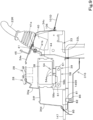
FIG. 16 is a side view of the communication device, a mounting stay, and a second side plate. -
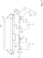
FIG. 17 is a plan view of the communication device, the mounting stay, and the second side plate. -
FIG. 18 is a perspective view of the communication device, the mounting stay, and the second side plate. -
FIG. 19 is a side perspective view of an indicator and a view hole. -
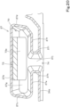
FIG. 20 is a cross-sectional plan view of a mobile terminal holder. -
FIG. 21 is a cross-sectional back view of the mobile terminal holder. -
FIG. 22 is a perspective view of an attachment portion of an IPU. -
FIG. 23 is an exploded perspective view of the IPU. - Example embodiments will now be described with reference to the accompanying drawings, wherein like reference numerals designate corresponding or identical elements throughout the various drawings. The drawings are to be viewed in an orientation in which the reference numerals are viewed correctly.
- An embodiment of the present invention is described below while referring to the drawings as appropriate.
-
FIG. 1 is a schematic side view illustrating an overall configuration of a working machine 1 according to the present embodiment. In the present embodiment, a backhoe, which is a swivel working machine, is illustrated as the working machine 1. - As illustrated in
FIG. 1 , the working machine 1 includes a machine body (swivel base) 2, a travelingdevice 3, and a working device 4. Themachine body 2 is provided with an operator'sseat 6 on which an operator (driver) sits and acanopy 15. As illustrated inFIG. 2 , the operator'sseat 6 includes aseat portion 6A and abackrest portion 6B. Theseat portion 6A is a portion on which the operator sits (places his or her buttocks and thighs). Thebackrest portion 6B is a portion against which the operator leans his or her back, and extends upward from a rear portion of theseat portion 6A. Thecanopy 15 is a four-pillar type canopy and may, for example, define a rollover protective structure (ROPS). - Note that although the working machine 1 provided with the canopy 15 (canopy-equipped working machine) is illustrated in the present embodiment, the working machine 1 may be a working machine 1 provided with a cabin surrounding the operator's seat 6 (cabin-equipped working machine) instead of the
canopy 15 or may be a working machine 1 without thecanopy 15 and without a cabin. - In the present embodiment, a direction (a direction indicated by arrow A1 in
FIG. 1 ) pointing forward of the operator sitting on the operator'sseat 6 of the working machine 1 is referred to as a forward direction (forward of the machine body), a direction (a direction indicated by arrow A2 inFIG. 1 ) pointing rearward of the operator is referred to as a rearward direction (rearward of the machine body), and a direction indicated by arrow A3 inFIG. 1 is referred to as a front-rear direction (machine body front-rear direction). A direction pointing leftward of the operator (near side ofFIG. 1 ) is referred to as a leftward direction, and a direction pointing rightward of the operator (deep side ofFIG. 1 ) is referred to as a rightward direction. - A horizontal direction orthogonal to the front-rear direction A3 is referred to as a machine body width direction (a width direction of the machine body 2). A direction pointing rightward or leftward from a central portion of the
machine body 2 in the width direction is referred to as being outward in the machine body width direction. That is, being outward in the machine body width direction is a direction pointing away in the machine body width direction from a center of themachine body 2 in the width direction. A direction opposite to the outward direction in the machine body width direction is referred to as being inward in the machine body width direction. That is, being inward in the machine body width direction is a direction pointing toward the center of themachine body 2 in the width direction in the machine body width direction. - As illustrated in
FIG. 1 , the travelingdevice 3 is a crawler-type traveling device that supports themachine body 2 and is capable of traveling. Although the crawler-type traveling device 3 is used in the present embodiment, this does not imply any limitation, and a wheel-type traveling device may be used. Adozer device 7 is attached to a front portion of the travelingdevice 3. - As illustrated in
FIG. 1 , themachine body 2 includes aswivel board 5 that is made of a thick plate member defining a bottom portion of themachine body 2. Theswivel board 5 is supported on the travelingdevice 3 with aswivel bearing 8 interposed therebetween so as to be capable of swiveling about a swivel axis X1 extending in an up-down direction. Theswivel board 5 is driven by a swivel motor (hydraulic motor) to swivel about the swivel axis X1. - Furthermore, the
machine body 2 includes, on a front portion, asupport bracket 9 and aswing bracket 10 that support the working device 4. Thesupport bracket 9 protrudes forward from the machine body 2 (seeFIG. 6 ). Theswing bracket 10 is attached to a front portion of thesupport bracket 9 so as to be capable of swinging about a vertical axis (an axis extending in the up-down direction). - As illustrated in
FIG. 1 , the working device 4 includes aboom 11, anarm 12, and a workingtool 13. In the present embodiment, a bucket is illustrated as the workingtool 13. A base portion of theboom 11 is pivotally attached to an upper portion of theswing bracket 10 so as to be rotatable about a horizontal axis (an axis extending in the machine body width direction). A workinglamp 110 is provided at an intermediate portion of theboom 11 in a longitudinal direction. In the present embodiment, the workinglamp 110 is attached to a right side of theboom 11. - The
arm 12 is pivotally attached to a front end of theboom 11 so as to be rotatable about the horizontal axis. Thebucket 13 is provided at a front end of thearm 12 so as to be capable of performing a shoveling action and a dumping action. - The
swing bracket 10 is made swingable by extension and contraction of a swing cylinder (not illustrated). - As illustrated in
FIG. 1 , afloor portion 21 on which the operator places his or her feet is provided on an upper surface of themachine body 2 in front of the operator'sseat 6. Thefloor portion 21 is, for example, configured such that a floor mat is laid on a step plate disposed above theswivel board 5 with a gap interposed therebetween and supported on theswivel board 5. - As illustrated in
FIG. 1 , aweight 25 that achieves weight balance with the working device 4 is disposed in a rear portion of themachine body 2. Furthermore, aprime mover 91 is mounted in a rear portion of themachine body 2. The working machine 1 according to the present embodiment is a small-sized backhoe in which the operator'sseat 6 is disposed above theprime mover 91. - As illustrated in
FIG. 3 , theprime mover 91 is disposed in the rear portion of themachine body 2 in an intermediate portion in the width direction. A coolingfan 100 is attached to one side (left portion) of theprime mover 91 in the machine body width direction. The coolingfan 100 is driven by theprime mover 91. In the present embodiment, the coolingfan 100 generates cooling air that flows from one side toward the other side (from left toward right) in the machine body width direction. - A
radiator 92, anoil cooler 93, and abattery 94 are disposed upstream (on the left of the prime mover 91) of the coolingfan 100 in the cooling air flowing direction (the direction in which the cooling air flows). Theradiator 92 is a cooler that cools a coolant for cooling theprime mover 91. Theoil cooler 93 is a cooler that cools a return hydraulic fluid returning from a hydraulic actuator such as a hydraulic cylinder or a hydraulic motor. Thebattery 94 is a battery that supplies electric power to an electric component provided in the working machine 1. - As illustrated in
FIG. 3 , aflywheel housing 199 in which a flywheel is contained is attached to the other side (right portion) of theprime mover 91 in the machine body width direction. Ahydraulic pump 95 is mounted on theflywheel housing 199. Thehydraulic pump 95 is driven by power of theprime mover 91 and delivers hydraulic fluid (hydraulic oil) that drives a hydraulic actuator such as a hydraulic motor or a hydraulic cylinder provided in the working machine 1. Thehydraulic pump 95 delivers a pilot pressure for activating a hydraulic valve or a hydraulic oil for a signal. Amuffler 200 to which exhaust gas from theprime mover 91 is guided is disposed above theflywheel housing 199. - As illustrated in
FIG. 3 , the coolingfan 100, theradiator 92, theoil cooler 93, thebattery 94, theflywheel housing 199, thehydraulic pump 95, and themuffler 200 are disposed inside aprime mover room 91A in which theprime mover 91 is contained. - The
prime mover room 91A includes theswivel board 5, theweight 25, amachine body cover 107, a partitioning wall 150 (seeFIG. 6 ), and a hood 101 (seeFIG. 4 ). - The cooling
fan 100 sucks outdoor air into theprime mover room 91A through anoutdoor air inlet 89 of thehood 101. The outdoor air (cooling air) taken into theprime mover room 91A is discharged through adischarge port 88 or the like after cooling theoil cooler 93, theradiator 92, and theprime mover 91. - As illustrated in
FIGS. 1 and2 , a drivingunit 18 including the operator'sseat 6, a travelinglever 16 disposed in front of the operator'sseat 6, and aconsole 17L disposed on the left of the operator'sseat 6 and aconsole 17R disposed on the right of the operator'sseat 6 is mounted on themachine body 2. The travelinglever 16 is an operation member for operating the travelingdevice 3. Theconsoles - As illustrated in
FIG. 2 , theleft console 17L includes acontrol lever 23L, a remote control valve (not illustrated), aconsole cover 22, anarm rest 26L, an operation lock lever (unload lever) 30, and a frame mechanism that supports the remote control valve, theconsole cover 22, thearm rest 26L, and theoperation lock lever 30. - The
control lever 23L is disposed in an upper front portion of theconsole 17L and can be swung forward, rearward, leftward, and rightward. The remote control valve is a pilot valve operated by thecontrol lever 23L and is disposed below thecontrol lever 23L. - The
console cover 22 is a member that covers members such as the remote control valve and the frame mechanism. The arm rest 26L is a member on which the operator places, for example, his or her elbow and is disposed behind thecontrol lever 23L. Theoperation lock lever 30 is a lever that switches a hydraulic actuator provided in the working machine 1 between an operable state and an inoperable state. - As illustrated in
FIG. 6 , theright console 17R is attached to asupport frame 142 standing on themachine body 2. Thesupport frame 142 stands on aswivel frame 14 that defines a framework of themachine body 2. Note that theconsole 17R may be directly attached to a member that defines themachine body 2. That is, theconsole 17R (aconsole bracket 33, which will be described later) is directly or indirectly attached to themachine body 2. - As illustrated in
FIG. 6 , theswivel frame 14 includes theswivel board 5, a pair of left and rightvertical ribs swivel board 5, and thepartitioning wall 150. The pair ofvertical ribs support bracket 9 fixed to a front portion of theswivel board 5. Thepartitioning wall 150 is disposed at intermediate portions of the pair ofvertical ribs vertical ribs vertical ribs - A rear portion of the left
vertical rib 224L is connected to afirst bracket member 151L with aconnection plate 225 interposed therebetween. A rear portion of the rightvertical ribs 224R is connected to asecond bracket member 151R. Thefirst bracket member 151L and thesecond bracket member 151R are constituent elements that define the swivel frame 14 (the machine body 2) together with theswivel board 5. - As illustrated in
FIGS. 2 ,4 ,5 ,6 , and7 , theright console 17R includes acontrol lever 23R, aremote control valve 40, anarm rest 26R, adozer lever 35, aconsole cover 34, aconsole bracket 33, acommunication device 38, adevice bracket 39, an electric component 36 (seeFIG. 10 ), a mountingstay 37, amobile terminal holder 27, a pair ofswitches 28, anaccelerator operator 29, astarter 31, and asocket 32. - The
control lever 23R is disposed in an upper front portion of theconsole 17R and can be swung forward, rearward, leftward, and rightward. Theremote control valve 40 is a pilot valve operated by thecontrol lever 23R and is disposed below thecontrol lever 23R. - The
control lever 23L and thecontrol lever 23R are described below. By swinging thecontrol levers machine body 2 are operated. Specifically, thecontrol levers boom 11, operation of swinging thearm 12, operation for a shoveling action and a dumping action of thebucket 13, and operation of swiveling themachine body 2. Specifically, thecontrol lever 23L operates, for example, a bucket control valve that controls a bucket cylinder C4 for driving thebucket 13 and a swiveling control valve that controls a swivel motor for swiveling themachine body 2. Thecontrol lever 23R operates, for example, a boom control valve that controls a boom cylinder C2 for driving theboom 11 and an arm control valve that controls an arm cylinder C3 for driving thearm 12. - The arm rest 26R is a member on which the operator places, for example, his or her elbow or wrist. The arm rest 26R is disposed behind the
control lever 23R. Thedozer lever 35 is a lever for operating thedozer device 7. Thedozer device 7 is operated by swinging thedozer lever 35 forward and rearward. Thedozer lever 35 is disposed outward (on the right) of thearm rest 26R in the machine body width direction. - The
console cover 34 is a molded resin. Theconsole cover 34 covers members such as theconsole bracket 33, theremote control valve 40, theelectric component 36, the mountingstay 37, thecommunication device 38, and thedevice bracket 39. - As illustrated in
FIGS. 8 ,9 ,10 , and11 , theconsole cover 34 includes a firstside wall portion 34a, a secondside wall portion 34b, afront wall portion 34c, arear wall portion 34d, and anupper wall portion 34e, and an inner portion surrounded by the firstside wall portion 34a, the secondside wall portion 34b, thefront wall portion 34c, therear wall portion 34d, and theupper wall portion 34e is hollow. A lower surface of theconsole cover 34 is opened. That is, theconsole cover 34 is opened on a lower side. - As illustrated in
FIGS. 3 and4 , acover body 101D disposed in a right portion of themachine body 2 and defines a portion of thehood 101 includes, in intermediate and rear portions of the upper surface in the front-rear direction, acutout portion 106 cut out in a range from the intermediate portion to the rear portion. Theconsole cover 34 is disposed above thecutout portion 106. Accordingly, a lower surface side of theconsole cover 34 is communicated with an inside (theprime mover room 91A) of thecover body 101D. - As illustrated in
FIG. 12 , the firstside wall portion 34a is located beside (on the right of) the operator'sseat 6 in the machine body width direction. As illustrated inFIGS. 8 and10 , the firstside wall portion 34a includes anopening 51 formed at an intermediate position in the front-rear direction and alid 52 that blocks theopening 51 in an openable and closable manner. - As illustrated in
FIG. 10 , the secondside wall portion 34b is provided beside (on the right of) the firstside wall portion 34a in the machine body width direction with a gap interposed therebetween. In other words, as illustrated inFIG. 12 , the secondside wall portion 34b is provided beside the firstside wall portion 34a with a gap interposed therebetween on a side opposite to the operator'sseat 6. - As illustrated in
FIG. 11 , thefront wall portion 34c couples a front portion of the firstside wall portion 34a and a front portion of the secondside wall portion 34b. Therear wall portion 34d couples a rear portion of the firstside wall portion 34a and a rear portion of the secondside wall portion 34b. As illustrated inFIGS. 8 ,9 , and10 , theupper wall portion 34e defines an upper portion of theconsole cover 34. Arear portion 34f of theupper wall portion 34e is located one-level lower than an intermediate portion and a front portion thereof in the front-rear direction. The rear portion of theupper wall portion 34e can be, for example, used as a tray on which a little item is placed. - As illustrated in
FIGS. 13 ,14 , and15 , theconsole bracket 33 includes afirst side plate 33L, a second side plate (support plate) 33R, amount 41, afront coupling plate 42F, arear coupling plate 42R, anintermediate plate 44, and anattachment plate 43. Thefirst side plate 33L is disposed outward (rightward) of the operator'sseat 6 in the machine body width direction. Thefirst side plate 33L is configured such that a front portion 33La thereof is elongated in the up-down direction and a rear portion 33Lb thereof extends rearward from a lower portion of the front portion 33La. Thefirst side plate 33L and thesecond side plate 33R are disposed apart from each other in the machine body width direction. Specifically, thesecond side plate 33R is disposed outward (rightward) of thefirst side plate 33L in the machine body width direction. - As illustrated in
FIG. 15 , asupport shaft 46 that protrudes rightward is provided on a front portion of thesecond side plate 33R. As illustrated inFIG. 7 , asupport cylinder 50 provided at a lower end of thedozer lever 35 is supported on thesupport shaft 46 so as to be rotatable about an axis extending in the machine body width direction. One end of anoperation cable 47 is coupled to anarm 48 fixed to thesupport cylinder 50. The other end of theoperation cable 47 is coupled to a control valve that controls a hydraulic cylinder for driving thedozer device 7 with an interlocking mechanism interposed therebetween. - As illustrated in
FIGS. 13 ,14 , and15 , themount 41 is disposed on the right of an upper front portion of thefirst side plate 33L and is fixed on a left surface of thefirst side plate 33L. Furthermore, themount 41 is disposed higher than the front portion of thesecond side plate 33R. Themount 41 includes anupper wall 41a and arear wall 41b. As illustrated inFIG. 9 , an upper portion of theremote control valve 40 is attached to theupper wall 41a of themount 41. The mountingstay 45 for mounting thearm rest 26R is fixed to a back surface of therear wall 41b with a bolt. - As illustrated in
FIGS. 9 and14 , theintermediate plate 44 is disposed below therear wall 41b of themount 41, and an upper portion thereof is fixed to a lower end of therear wall 41b. Theintermediate plate 44 is disposed between a rear end of the front portion of thefirst side plate 33L and thesecond side plate 33R and couples thefirst side plate 33L and thesecond side plate 33R. Aseal contact portion 44a is provided on a lower end portion of theintermediate plate 44. - As illustrated in
FIG. 15 , thefront coupling plate 42F is disposed between a lower portion of the front portion of thefirst side plate 33L and the front portion of thesecond side plate 33R and couples thefirst side plate 33L and thesecond side plate 33R. As illustrated inFIG. 13 , therear coupling plate 42R is disposed between the rear portion of thefirst side plate 33L and the rear portion of thesecond side plate 33R and couples thefirst side plate 33L and thesecond side plate 33R. Theattachment plate 43 is made of a plate member that is long in the front-rear direction, and is disposed below thefirst side plate 33L so that a plate surface thereof faces the up-down direction, and a right portion thereof is fixed to a lower end of thefirst side plate 33L. - As illustrated in
FIGS. 6 and13 , theattachment plate 43 is superimposed on an upper surface of an upperside frame portion 145R provided on an upper right portion of thesupport frame 142 and is attached to the upperside frame portion 145R with a bolt or the like. That is, theconsole bracket 33 is attached to thesupport frame 142 and is attached to themachine body 2 with thesupport frame 142 interposed therebetween. Note that theconsole bracket 33 may be attached to a member that defines themachine body 2. That is, theconsole bracket 33 is directly or indirectly attached to themachine body 2. - As illustrated in
FIGS. 9 ,10 , and11 , theconsole bracket 33 is covered with theconsole cover 34. Specifically, a left side of theconsole bracket 33 is covered with the firstside wall portion 34a of theconsole cover 34, a right side of theconsole bracket 33 is covered with the secondside wall portion 34b, a front side of theconsole bracket 33 is covered with thefront wall portion 34c, a rear side of theconsole bracket 33 is covered with therear wall portion 34d, and an upper side of theconsole bracket 33 is covered with theupper wall portion 34e. - The
console cover 34 is attached to theconsole bracket 33 with a screw or the like. Specifically, therear portion 34f of theupper wall portion 34e of theconsole cover 34 is attached to a mounting stay 53 (seeFIG. 13 ) provided in the rear portion of theconsole bracket 33, and thefront wall portion 34c of theconsole cover 34 is attached to thefront coupling plate 42F of theconsole bracket 33. - The
communication device 38 is a direct communication unit (DCU) that performs data communication with an external device (not illustrated). Thecommunication device 38 receives data from an information processing unit (IPU) (information collecting unit) 59, which is an information processing device that will be described later. Furthermore, thecommunication device 38 transmits data such as data received from theIPU 59 or positional information to a server. The server is, for example, a server installed at a manufacturer (manufacturing company) that manufactures the working machine 1 or a server installed at a dealer (sales and maintenance company) that does sales and maintenance of the working machine 1. - The
communication device 38 is a waterproof device configured such that members such as an electronic substrate, a communication antenna 49 (seeFIG. 16 ), and a positioning antenna (GPS antenna) are stored in a case made of a resin. Thecommunication antenna 49 and the positioning antenna are attached to the electronic substrate. Thecommunication antenna 49 is, for example, a Long Term Evolution antenna (LTE antenna). Thecommunication antenna 49 is an antenna for communication with the server. - Since the
communication antenna 49 is included in thecommunication device 38, thecommunication device 38 can maintain a communicable state during an illegal act (e.g., an act of removing the communication device 38) such as theft and can report the act to a predetermined destination. - The positioning antenna receives a satellite signal transmitted from a positioning satellite. The working machine 1 detects a position thereof (measured position information including latitude and longitude) by a positioning system on the basis of the satellite signal received by the positioning antenna. Specifically, the working machine 1 finds a position and an orientation of the working machine 1 by using a known Global Positioning System (GPS) (for example, by RTK-GPS suitable for measurement of a position of a mobile body), which is an example of a Global Navigation Satellite System (GNSS). That is, the working machine 1 communicates with a base station (reference station) installed at a known position, and the base station transmits, to the working machine 1, measured position data (correction information) obtained by receiving a radio wave from the positioning satellite. The working machine 1 detects a position thereof (latitude and longitude) on the basis of the measured position data obtained by receiving a radio wave from the positioning satellite and the measured position data obtained from the base station. The
communication device 38 transmits and receives positional information. - As illustrated in
FIGS. 7 ,9 ,10 ,11 , and15 , thedevice bracket 39 is a bracket to which thecommunication device 38 is attached. Thecommunication device 38 is attached to theconsole bracket 33 with thedevice bracket 39 interposed therebetween. Thedevice bracket 39 and thecommunication device 38 are disposed inside theconsole cover 22. That is, thecommunication device 38 is disposed inside theconsole 17R. By disposing thecommunication device 38 inside theconsole 17R, theft of thecommunication device 38 can be prevented or reduced. In addition, outer appearance of the working machine 1 can be improved. Furthermore, disposing thecommunication device 38 inside theconsole 17R makes it unnecessary to provide a cover exclusive for thecommunication device 38. - As illustrated in
FIGS. 7 ,9 ,10 ,11 , and15 , thecommunication device 38 is disposed on the right (on a side opposite to the operator's seat 6) of a rear portion of theconsole bracket 33. Specifically, thecommunication device 38 is disposed on the right of the rear portion of the second side plate (support plate) 33R. Thecommunication device 38 is located at an intermediate portion of the console cover 34 (theconsole 17R) in the front-rear direction (seeFIG. 9 ). - As illustrated in
FIG. 3 , thecommunication device 38 is disposed above thehydraulic pump 95 and themuffler 200. - As illustrated in
FIGS. 10 and11 , thecommunication device 38 is disposed between the firstside wall portion 34a and the secondside wall portion 34b so as to be located closer to the secondside wall portion 34b. Thecommunication device 38 is disposed so that a devicefront surface 38A thereof faces outward in the machine body width direction and faces the secondside wall portion 34b. As illustrated inFIG. 15 , thecommunication device 38 includes anindicator 54. Theindicator 54 is provided on an intermediate portion, in the front-rear direction, of a lower portion of the devicefront surface 38A of thecommunication device 38. Theindicator 54 displays, for example, an operating state (communication state) of thecommunication device 38. Theindicator 54 includes threeindicator lamps 54a. As illustrated inFIGS. 10 ,11 , and19 , the secondside wall portion 34b includes aview hole 55 through which theindicator 54 is viewable from an outside of theconsole 17R. - The
indicator 54 can be easily checked from a position outward of the working machine 1 in the machine body width direction by disposing thecommunication device 38 including theindicator 54 on the devicefront surface 38A so that the devicefront surface 38A faces outward in the machine body width direction and faces the secondside wall portion 34b and forming theview hole 55 in the secondside wall portion 34b. - As illustrated in
FIGS. 10 and11 , the second side plate (support plate) 33R of theconsole bracket 33 is disposed between the firstside wall portion 34a and thecommunication device 38. Thedevice bracket 39 is disposed between thesecond side plate 33R and thecommunication device 38 and is attached to thesecond side plate 33R. Thecommunication device 38 can be thus disposed between the firstside wall portion 34a and the secondside wall portion 34b so as to be located closer to the secondside wall portion 34b. By widening the secondside wall portion 34b outward in the machine body width direction to dispose thecommunication device 38 inside theconsole 17R, a space where thecommunication device 38 is disposed in theconsole 17R (the console cover 34) can be easily secured. - As illustrated in
FIG. 15 , thedevice bracket 39 includes anattachment plate 56, avertical member 57, and a mountingstay 58. Theattachment plate 56 is a metal plate member having a substantially rectangular shape in side view. Theattachment plate 56 is disposed on a device backsurface 38B of thecommunication device 38 opposite to the devicefront surface 38A. Thecommunication device 38 is attached to four corners of theattachment plate 56 with a screw or the like. Theattachment plate 56 includes acutout portion 60 that passes through theattachment plate 56. As illustrated inFIG. 16 , thecommunication antenna 49 is located at a position corresponding to thecutout portion 60 so that theattachment plate 56 does not block a radio wave. - The
vertical member 57 is made of channel steel and is disposed on a left surface of theattachment plate 56 and extends in the up-down direction so that an opened side thereof faces rightward. Thevertical member 57 is fixed to a left surface of the mountingstay 58 by welding or the like. - The mounting
stay 58 is a plate member, and includes anupper wall 58a whose plate surface faces the up-down direction and avertical wall 58b that extends downward from a left end of theupper wall 58a. Theupper wall 58a of the mountingstay 58 is fixed to a lower end of thevertical member 57. Thevertical wall 58b of the mountingstay 58 is superimposed on an intermediate portion, in the up-down direction, of a right surface of thesecond side plate 33R and is fixed to thesecond side plate 33R with a bolt 61 (seeFIG. 10 ). - Since the
device bracket 39 is attached to thesecond side plate 33R, thecommunication antenna 49 is located higher than thesecond side plate 33R, as illustrated inFIG. 16 . That is, thedevice bracket 39 is attached to thesecond side plate 33R so that thecommunication antenna 49 is disposed higher than the second side plate (support plate) 33R. Since thecommunication antenna 49 is located higher than thesecond side plate 33R, thesecond side plate 33R does not block a radio wave. - As illustrated in
FIGS. 10 and14 , theelectric component 36 is disposed between thesecond side plate 33R and the firstside wall portion 34a. In the present embodiment, theelectric component 36 is a fuse box in which a fuse is attached. Theelectric component 36 is attached to the mountingstay 37. - As illustrated in
FIG. 18 , a pair of mounting stays 37 are arranged in the front-rear direction on a left side of the rear portion of thesecond side plate 33R. Each of the mounting stays 37 includes anupper plate portion 37a, alower plate portion 37b, and avertical plate portion 37c. Thelower plate portion 37b is disposed below theupper plate portion 37a with a gap interposed therebetween. Thevertical plate portion 37c couples a right end of theupper plate portion 37a and a right end of thelower plate portion 37b. Thevertical plate portion 37c is fixed to thesecond side plate 33R so that a lower portion thereof is superimposed on the left surface of thesecond side plate 33R. Accordingly, the mountingstay 37 is fixed to thesecond side plate 33R so as to protrude upward from thesecond side plate 33R. - As illustrated in
FIG. 10 , theelectric component 36 includes aninsertion portion 36a in an upper portion and a lower portion, and theelectric component 36 is attached to the mountingstay 37 so that theupper plate portion 37a and thelower plate portion 37b are inserted into theinsertion portions 36a. Note that theelectric component 36 faces theopening 51 of theconsole cover 34, and theelectric component 36 can be accessed (e.g., the fuse can be replaced) from an outside of theconsole cover 34 when thelid 52 is removed. - As illustrated in
FIGS. 16 ,17 , and18 , the mountingstay 37 includes acutout portion 62. Thecutout portion 62 is provided in a range from a right front portion of theupper plate portion 37a to an upper front portion of thevertical plate portion 37c. As illustrated inFIG. 16 , thecutout portion 62 is located at a position corresponding to thecommunication antenna 49 in the machine body width direction. That is, the mountingstay 37 includes thecutout portion 62 formed by cutting out a portion corresponding to thecommunication antenna 49. In the present embodiment, the front-side communication antenna 49 is located at a position corresponding to thecutout portion 62 of the front-side mounting stay 37. - In disposing the
communication device 38, it is required that no object that blocks a radio wave be present within a predetermined distance from thecommunication antenna 49. By forming, in the mountingstay 37, thecutout portion 62 by cutting out a portion corresponding to thecommunication antenna 49, it is possible to prevent the mountingstay 37 from blocking a radio wave. That is, thecutout portion 62 can accomplish the requirement that no object that blocks a radio wave be present within a predetermined distance from thecommunication antenna 49. For example, if thecutout portion 62 is not formed in the mountingstay 37, thecommunication device 38 needs to be separated by a predetermined distance from the mountingstay 37. However, by forming thecutout portion 62 in the mountingstay 37, thecommunication device 38 can be disposed close to the mounting stay, and therefore thecommunication device 38 can be disposed in theconsole 17R in a contact manner (the secondside wall portion 34b can be prevented from being widened more than necessary). - Note that in the present embodiment, no object that blocks a radio wave is present within a predetermined distance from the
communication device 38 rightward, forward, rearward, upward, and downward of thecommunication device 38. In the present embodiment, the rear-side mounting stay 37 also has the same shape as the front-side mounting stay 37 so that the shapes of the mounting stays 37 are made uniform although only the front-side mounting stay 37 needs thecutout portion 62. - As illustrated in
FIGS. 8 and12 , themobile terminal holder 27, the pair ofswitches 28, theaccelerator operator 29, and thesocket 32 are provided on the upper portion of theconsole cover 34. - First, arrangement of these members is described.
- As illustrated in
FIGS. 8 and12 , themobile terminal holder 27 is provided in an intermediate portion of the console cover 34 (theconsole 17R) in the front-rear direction so as to be located closer to the operator'sseat 6 than a center of theconsole cover 34 in the machine body width direction. As illustrated inFIG. 12 , themobile terminal holder 27 is provided beside (on the right of) theseat portion 6A so as to be located forward of thebackrest portion 6B. - As illustrated in
FIG. 12 , the pair ofswitches 28 are disposed beside the operator's seat 6 (theseat portion 6A) so as to be located forward of thebackrest portion 6B. The pair ofswitches 28 are provided on a side opposite to the operator'sseat 6 in the machine body width direction with respect to the center of the console cover 34 (theconsole 17R) in the machine body width direction. The pair ofswitches 28 are arranged in the front-rear direction. Furthermore, the pair ofswitches 28 are provided in an intermediate portion of the console cover 34 (theconsole 17R) in the front-rear direction. Furthermore, the pair ofswitches 28 are disposed outward of (on the right of) themobile terminal holder 27 in the machine body width direction. - As illustrated in
FIG. 12 , theaccelerator operator 29 is provided between themobile terminal holder 27 and the pair ofswitches 28. As illustrated inFIG. 4 , thestarter 31 and thesocket 32 are provided on avertical surface wall 34g between the intermediate portion of theconsole cover 34 in the front-rear direction and therear portion 34f. In the present embodiment, thestarter 31 is provided in a left portion of thevertical surface wall 34g, and thesocket 32 is provided in a right portion of thevertical surface wall 34g. - Note that in
FIG. 8 ,reference sign 64 represents a hole for avoiding interference with an upper portion of theremote control valve 40.Reference sign 65 represents an insertion hole through which the mountingstay 45 protrudes from an inside of theconsole 17R.Reference sign 66 represents a guide hole through which thedozer lever 35 protrudes from an inside of theconsole 17R.Reference sign 67 represents an attachment hole for attaching theaccelerator operator 29.Reference sign 68 represents an attachment portion for attaching thestarter 31.Reference sign 69 represents an attachment portion for attaching thesocket 32. - Next, the
mobile terminal holder 27, the pair ofswitches 28, theaccelerator operator 29, and thesocket 32 are described in detail. - The
mobile terminal holder 27 is a portion that holds amobile terminal 73 such as a smartphone. - As illustrated in
FIG. 10 , themobile terminal holder 27 is recessed from an upper side to a lower side and includes an upperend edge portion 27a that forms an upper end opening and an internal space (mobile terminal container) 70 in which themobile terminal 73 is contained. Accordingly, themobile terminal 73 can be inserted into the mobile terminal container 70 (the mobile terminal holder 27) from above. Themobile terminal holder 27 can hold themobile terminal 73 so that adisplay screen 73a of themobile terminal 73 faces the operator'sseat 6. - As illustrated in
FIGS. 20 and21 , the internal space (the mobile terminal container) 70 of themobile terminal holder 27 is formed by afirst wall 27b, asecond wall 27c, athird wall 27d, afourth wall 27e, afifth wall 27f, and asixth wall 27g. As illustrated inFIG. 21 , thefirst wall 27b is a wall portion which a surface of themobile terminal 73 opposite to thedisplay screen 73a faces in a state where themobile terminal 73 is contained so that thedisplay screen 73a of themobile terminal 73 faces the operator'sseat 6. Thefirst wall 27b forms a right surface portion of an inner surface of the mobileterminal container 70. As illustrated inFIG. 21 , thefirst wall 27b is inclined away from the operator'sseat 6 toward an upper side. In this way, themobile terminal 73 can be held by themobile terminal holder 27 so that the operator sitting on the operator'sseat 6 can easily view thedisplay screen 73a of themobile terminal 73. - As illustrated in
FIG. 20 , thesecond wall 27c is a wall portion extending leftward from a front end of thefirst wall 27b and forms a front surface portion of the inner surface of the mobileterminal container 70. Thethird wall 27d is a wall portion extending leftward from a rear end of thefirst wall 27b and forms a rear surface portion of the inner surface of the mobileterminal container 70. Thefourth wall 27e is a wall portion extending rearward from a left end of thesecond wall 27c and forms a front portion of a left surface portion of the inner surface of the mobileterminal container 70. Thefifth wall 27f is a wall portion extending forward from a left end of thethird wall 27d and forms a rear portion of the left surface portion of the inner surface of the mobileterminal container 70. A gap is present between a rear end of thefourth wall 27e and a front end of thefifth wall 27f. - As illustrated in
FIG. 21 , thesixth wall 27g is a wall portion extending leftward from a lower end of thefirst wall 27b and defines a bottom portion that supports a lower end of themobile terminal 73. In other words, thesixth wall 27g forma a bottom surface portion (lower surface portion) of the inner surface of the mobileterminal container 70. - As illustrated in
FIGS. 20 and21 , themobile terminal holder 27 includes agroove portion 74 on the operator'sseat 6 side. Thegroove portion 74 is formed over a range from the upperend edge portion 27a to thebottom portion 27g and is opened from the mobile terminal container 70 (the internal space of the mobile terminal holder 27) toward the operator'sseat 6. Thegroove portion 74 is formed by aseventh wall 27h, aneighth wall 27i, and aninth wall 27j. As illustrated inFIG. 20 , theseventh wall 27h extends leftward from the rear end of thefourth wall 27e and is connected to the firstside wall portion 34a of theconsole cover 34. Theeighth wall 27i extends leftward from the front end of thefifth wall 27f and is connected to the firstside wall portion 34a of theconsole cover 34. As illustrated inFIG. 21 , theninth wall 27j extends leftward from a left end of thesixth wall 27g and is connected to the firstside wall portion 34a of theconsole cover 34. Theninth wall 27j is inclined downward toward an inner side in the machine body width direction (toward the operator's seat 6). - Since the
mobile terminal holder 27 includes thegroove portion 74, a foreign substance such as water or dust that has entered the mobileterminal container 70 can be easily removed from the inside of the mobileterminal container 70 through thegroove portion 74. - The pair of
switches 28 are, for example, light switches. Specifically, one switch (front-side switch) 28F is a switch for turning ON and OFF the workinglamp 7 attached to theboom 11. The other switch (rear-side switch) 28R is a switch for turning ON and OFF a revolving light 71 (seeFIG. 2 ) provided on aroof 19 of thecanopy 15. Note that the switch 28F may be a switch for turning ON and OFF a headlight 72 (seeFIG. 2 ) provided on theroof 19 of thecanopy 15. The number ofswitches 28 may be one or may be three or more. That is, it is only necessary that at least oneswitch 28 be provided. - The
switches 28 are not restrictive, and can be, for example, seesaw switches (rocker switches). One of operation of turning ON and operation of turning OFF is performed by pressing a front end, and the other one of the operation of turning ON and the operation of turning OFF is performed by pressing a rear end. - As illustrated in
FIG. 12 , each of theswitches 28 has a rectangular shape in plan view, and is inclined away from the operator's seat 6 (outward in the machine body width direction) toward a front side in plan view. - As illustrated in
FIGS. 8 and10 , the pair ofswitches 28 are provided at a position corresponding to a position above thecommunication device 38. - Since the
switches 28 are inclined away from the operator'sseat 6 toward the front side in plan view, the operator can press theswitches 28 without increasing an angle by which his or her arm is opened or twisting his or her wrist. In other words, the operator can press the switches in a natural manner. - Furthermore, since the
switches 28 are provided on a side opposite to the operator'sseat 6 in the machine body width direction with respect to the center of theconsole 17R in the machine body width direction, the operator can operate theswitches 28 while keeping an arm away from his or her side by an appropriate distance, and therefore operability of theswitch 28 is good. Furthermore, since theswitches 28 are provided at a position corresponding to a position above thecommunication device 38, a place where theswitches 28 are installed can be secured. - The
accelerator operator 29 decides a rotational speed of theprime mover 91 by operating a rotational speed adjuster (governor) for setting the rotational speed of theprime mover 91. Specifically, theaccelerator operator 29 includes an accelerator dial 29A manually operated by the operator. The accelerator dial 29A is, for example, connected to a controller. The controller acquires a rotational speed indicated by the accelerator dial 29A, and outputs a command signal to the rotational speed adjuster so that the rotational speed of theprime mover 91 matches the rotational speed indicated by the accelerator dial 29A. - The
starter 31 is a device for starting an engine. Thesocket 32 is a USB socket, a cigar socket, or the like. - As illustrated in
FIG. 4 , theIPU 59 is disposed behind a lower portion of the operator'sseat 6. TheIPU 59 is an "information processing device" that temporarily accumulates information concerning the working machine 1 and performs predetermined processing (e.g., compression processing). TheIPU 59 is connected to a communication port of an on-board communication network (not illustrated), a communication port of an On-Board Diagnostics (OBD), or the like by a harness. The on-board communication network is a Controller Area Network (CAN), a FlexRay, or the like mounted on the working machine 1. TheIPU 59 receives information concerning the working machine 1 from the communication network or the On-Board Diagnostics. TheIPU 59 is connected to thecommunication device 38 by aharness 64, and transmits data to thecommunication device 38. TheIPU 59 and thecommunication device 38 are connected to a power supply port (not illustrated) by a harness, and is supplied with power from the power supply port. - As illustrated in
FIGS. 22 and23 , theIPU 59 includes anIPU body 75 and acase body 76 in which theIPU body 75 is contained. Thecase body 76 includes anattachment plate 76A to which theIPU body 75 is attached and acover body 76B attached to theattachment plate 76A so as to cover theIPU body 75. - The
IPU 59 is attached to an attachment portion 77 of theROPS 15. The attachment portion 77 includes a base member 77A and a coupler 77B. The base member 77A is attached to a rear upper frame 147 (seeFIG. 6 ) provided in a rear portion of an upper portion of thesupport frame 142. The coupler 77B couples aconnector 78A of theROPS 15 and the base member 77A. Theconnector 78A of theROPS 15 is a portion that connects a lower end portion of a leftrear pillar portion 78L and a lower end portion of a rightrear pillar portion 78R of theROPS 15. Abracket member 79 is fixed to a rear surface of the case body 76 (seeFIG. 4 ), and the IPU59 is attached to theROPS 15 by attaching thebracket member 79 to the coupler 77B. - As illustrated in
FIGS. 3 and10 , the working machine 1 includes aheat blocker 316 that blocks heat from theprime mover 91 side (e.g., theprime mover 91, themuffler 200, and the hydraulic pump 95) so that the heat does not transmit to thecommunication device 38. Theheat blocker 316 covers thecommunication device 38 from below and blocks heat such as cooling air (hot air), convection heat, or radiation heat from theprime mover 91 side so that the heat does not transmit to thecommunication device 38. - An example embodiment of the present invention provides the working machine 1 described in the following items.
- (Item 1) A working machine 1 comprising: a
machine body 2; an operator'sseat 6 mounted on themachine body 2; aconsole 17R disposed beside the operator'sseat 6; and acommunication device 38 disposed inside theconsole 17R. - With the working machine 1 according to Item 1, theft of the
communication device 38 can be prevented or reduced by disposing thecommunication device 38 inside theconsole 17R. In addition, outer appearance of the working machine 1 can be improved. - (Item 2) The working machine according to Item 1, wherein the
console 17R includes a firstside wall portion 34a located beside the operator'sseat 6 and a secondside wall portion 34b provided beside the firstside wall portion 34a with a gap interposed therebetween on a side opposite to the operator'sseat 6, and thecommunication device 38 is disposed between the firstside wall portion 34a and the secondside wall portion 34b so as to be located closer to the secondside wall portion 34b. - With the working machine 1 according to
Item 2, in disposing thecommunication device 38 inside theconsole 17R, a space where the communication device is disposed in theconsole 17R can be easily secured by widening the secondside wall portion 34b outward in the machine body width direction. - (Item 3) The working machine according to
Item 2, wherein thecommunication device 38 includes anindicator 54 provided on a side facing the secondside wall portion 34b, and the secondside wall portion 34b includes aview hole 55 through which theindicator 54 is viewable from an outside of theconsole 17R. - With the working machine 1 according to
Item 3, theindicator 54 can be checked from an outside of the working machine 1 in the machine body width direction. - (Item 4) The working machine according to
Item device bracket 39 to which thecommunication device 38 is attached, wherein theconsole 17R includes aconsole bracket 33 directly or indirectly attached to themachine body 2, theconsole bracket 33 includes asupport plate 33R disposed between the firstside wall portion 34a and thecommunication device 38, and thedevice bracket 39 is disposed between the support plate (33R) and thecommunication device 38 and is attached to thesupport plate 33R. - With the working machine 1 according to Item 4, the
communication device 38 can be disposed between the firstside wall portion 34a and the secondside wall portion 34b so as to be closer to the secondside wall portion 34b. - (Item 5) The working machine according to Item 4, further comprising: an
electric component 36 disposed between thesupport plate 33R and the firstside wall portion 34a; and a mountingstay 37 to which theelectric component 36 is attached, wherein thecommunication device 38 includes acommunication antenna 49, thedevice bracket 39 is attached to thesupport plate 33R so that thecommunication antenna 49 is disposed higher than thesupport plate 33R, and the mountingstay 37 is fixed to thesupport plate 33R so as to protrude upward from thesupport plate 33R and includes acutout portion 62 formed by cutting out a portion corresponding to thecommunication antenna 49. - With the working machine 1 according to
Item 5, in disposing thecommunication device 38, it is required that no object that blocks a radio wave be present within a predetermined distance from thecommunication antenna 49. By attaching thedevice bracket 39 to thesupport plate 33R so that thecommunication antenna 49 is disposed higher than thesupport plate 33R, it is possible to prevent thesupport plate 33R from blocking a radio wave. Furthermore, by forming thecutout portion 62 in a portion of the mountingstay 37 that corresponds to thecommunication antenna 49, it is possible to prevent the mountingstay 37 from blocking a radio wave. Furthermore, by forming thecutout portion 62 in the mountingstay 37, thecommunication device 38 can be disposed close to the mountingstay 37, and thecommunication device 38 can be disposed in theconsole 17R in a compact manner. - (Item 6) The working machine according to any one of Items 1 to 5, wherein the
console 17R is disposed beside the operator'sseat 6 in a machine body width direction and includes amobile terminal holder 27 that is capable of holding amobile terminal 73 so that adisplay screen 73a of themobile terminal 73 faces the operator'sseat 6, and themobile terminal holder 27 is provided closer to the operator'sseat 6 in the machine body width direction than a center of theconsole 17R in the machine body width direction. - With the working machine 1 according to
Item 6, themobile terminal 73 can be placed close to the operator in such a manner that the operator can see thedisplay screen 73a. - (Item 7) The working machine according to
Item 6, wherein themobile terminal holder 27 is recessed from an upper side toward a lower side and includes an upperend edge portion 27a that forms an upper end opening, abottom portion 27g that supports a lower end of themobile terminal 73, and agroove portion 74 that is provided over a range from the upperend edge portion 27a to thebottom portion 27g and is opened from aninternal space 70 of themobile terminal holder 27 toward the operator'sseat 6. - With the working machine 1 according to
Item 7, a foreign substance such as water or dust that has entered themobile terminal holder 27 can be easily removed from the inside of themobile terminal holder 27 through thegroove portion 74. - (Item 8) The working machine according to
Item mobile terminal holder 27 includes awall portion 27b which a surface of themobile terminal 73 opposite to thedisplay screen 73a faces in a state where themobile terminal 73 is contained so that thedisplay screen 73a faces the operator'sseat 6, and thewall portion 27b is inclined away from the operator'sseat 6 toward an upper side. - With the working machine 1 according to
Item 8, themobile terminal 73 can be held by themobile terminal holder 27 so that the operator sitting on the operator'sseat 6 can easily view thedisplay screen 73a of themobile terminal 73. - (Item 9) The working machine according to any one of Items 1 to 8, wherein the console (17R) includes at least one
switch 28 provided on an upper portion of theconsole 17R, the operator'sseat 6 includes aseat portion 6A on which an operator sits and abackrest portion 6B against which the operator leans his or her back, and theswitch 28 is disposed beside the operator'sseat 6 and is located forward of thebackrest portion 6B, and is inclined away from the operator'sseat 6 toward a front side in plan view. - With the working machine 1 according to
Item 9, the operator can press theswitch 28 without increasing an angle by which his or her arm is opened or twisting his or her wrist. In other words, the operator can press theswitch 28 in a natural manner. - (Item 10) The working machine according to
Item 9, wherein theswitch 28 is provided on a side opposite to the operator'sseat 6 in a machine body width direction with respect to a center of theconsole 17R in the machine body width direction and is located at a position corresponding to a position above thecommunication device 38. - With the working machine 1 according to
Item 10, theswitch 28 is provided on a side opposite to the operator'sseat 6 in the machine body width direction with respect to a center of theconsole 17R in the machine body width direction, and therefore the operator can operate theswitch 28 while keeping an arm away from his or her side by an appropriate distance, and operability of theswitch 28 is good. Furthermore, since theswitch 28 is provided at a position corresponding to a position above thecommunication device 38, a place where theswitch 28 is installed can be secured. - (Item 11) The working machine according to any one of Items 1 to 10, further comprising: a
prime mover 91 mounted on themachine body 2; ahood 101 to cover theprime mover 91; and asupport frame 142 to support thehood 101, thesupport frame 142 standing on themachine body 2 inside thehood 101, wherein theconsole 17R is attached to thesupport frame 142. - With the working machine 1 according to
Item 11, theconsole 17R can be firmly supported, and thecommunication device 38 can be firmly supported. - While example embodiments of the present invention have been described above, it is to be understood that variations and modifications will be apparent to those skilled in the art without departing from the scope and spirit of the present invention. The scope of the present invention, therefore, is to be determined solely by the following claims.
Claims (11)
- A working machine comprising:a machine body (2);an operator's seat (6) mounted on the machine body (2);a console (17R) disposed beside the operator's seat (6); anda communication device (38) disposed inside the console (17R).
- The working machine according to claim 1, whereinthe console (17R) includes a first side wall portion (34a) located beside the operator's seat (6) and a second side wall portion (34b) provided beside the first side wall portion (34a) with a gap interposed therebetween on a side opposite to the operator's seat (6), andthe communication device (38) is disposed between the first side wall portion (34a) and the second side wall portion (34b) so as to be located closer to the second side wall portion (34b).
- The working machine according to claim 2, whereinthe communication device (38) includes an indicator (54) provided on a side facing the second side wall portion (34b), andthe second side wall portion (34b) includes a view hole (55) through which the indicator (54) is viewable from an outside of the console (17R).
- The working machine according to claim 2 or 3, further comprising a device bracket (39) to which the communication device (38) is attached, whereinthe console (17R) includes a console bracket (33) directly or indirectly attached to the machine body (2),the console bracket (33) includes a support plate (33R) disposed between the first side wall portion (34a) and the communication device (38), andthe device bracket (39) is disposed between the support plate (33R) and the communication device (38) and is attached to the support plate (33R).
- The working machine according to claim 4, further comprising:an electric component (36) disposed between the support plate (33R) and the first side wall portion (34a); anda mounting stay (37) to which the electric component (36) is attached, whereinthe communication device (38) includes a communication antenna (49),the device bracket (39) is attached to the support plate (33R) so that the communication antenna (49) is disposed higher than the support plate (33R), andthe mounting stay (37) is fixed to the support plate (33R) so as to protrude upward from the support plate (33R) and includes a cutout portion (62) formed by cutting out a portion corresponding to the communication antenna (49).
- The working machine according to any one of claims 1 to 5, whereinthe console (17R) is disposed beside the operator's seat (6) in a machine body width direction and includes a mobile terminal holder (27) that is capable of holding a mobile terminal (73) so that a display screen (73a) of the mobile terminal (73) faces the operator's seat (6), andthe mobile terminal holder (27) is provided closer to the operator's seat (6) in the machine body width direction than a center of the console (17R) in the machine body width direction.
- The working machine according to claim 6, wherein
the mobile terminal holder (27) is recessed from an upper side toward a lower side and includes an upper end edge portion (27a) that forms an upper end opening, a bottom portion (27g) that supports a lower end of the mobile terminal (73), and a groove portion (74) that is provided over a range from the upper end edge portion (27a) to the bottom portion (27g) and is opened from an internal space (70) of the mobile terminal holder (27) toward the operator's seat (6). - The working machine according to claim 6 or 7, whereinthe mobile terminal holder (27) includes a wall portion (27b) which a surface of the mobile terminal (73) opposite to the display screen (73a) faces in a state where the mobile terminal (73) is contained so that the display screen (73a) faces the operator's seat (6), andthe wall portion (27b) is inclined away from the operator's seat (6) toward an upper side.
- The working machine according to any one of claims 1 to 8, whereinthe console (17R) includes at least one switch (28) provided on an upper portion of the console (17R),the operator's seat (6) includes a seat portion (6A) on which an operator sits and a backrest portion (6B) against which the operator leans his or her back, andthe switch (28) is disposed beside the operator's seat (6) and is located forward of the backrest portion (6B), and is inclined away from the operator's seat (6) toward a front side in plan view.
- The working machine according to claim 9, wherein
the switch (28) is provided on a side opposite to the operator's seat (6) in a machine body width direction with respect to a center of the console (17R) in the machine body width direction and is located at a position corresponding to a position above the communication device (38). - The working machine according to any one of claims 1 to 10, further comprising:a prime mover (91) mounted on the machine body (2);a hood (101) to cover the prime mover (91); anda support frame (142) to support the hood (101), the support frame (142) standing on the machine body (2) inside the hood (101), whereinthe console (17R) is attached to the support frame (142).
Applications Claiming Priority (1)
| Application Number | Priority Date | Filing Date | Title |
|---|---|---|---|
| JP2023107904A JP2025006872A (en) | 2023-06-30 | 2023-06-30 | Work equipment |
Publications (2)
| Publication Number | Publication Date |
|---|---|
| EP4484656A2 true EP4484656A2 (en) | 2025-01-01 |
| EP4484656A3 EP4484656A3 (en) | 2025-01-15 |
Family
ID=91539915
Family Applications (1)
| Application Number | Title | Priority Date | Filing Date |
|---|---|---|---|
| EP24182108.1A Pending EP4484656A3 (en) | 2023-06-30 | 2024-06-13 | Working machine |
Country Status (3)
| Country | Link |
|---|---|
| US (1) | US20250003187A1 (en) |
| EP (1) | EP4484656A3 (en) |
| JP (1) | JP2025006872A (en) |
Citations (1)
| Publication number | Priority date | Publication date | Assignee | Title |
|---|---|---|---|---|
| JP2021150829A (en) | 2020-03-19 | 2021-09-27 | 株式会社クボタ | Communication unit and work machine |
Family Cites Families (9)
| Publication number | Priority date | Publication date | Assignee | Title |
|---|---|---|---|---|
| JP2010216154A (en) * | 2009-03-17 | 2010-09-30 | Hitachi Constr Mach Co Ltd | Construction machinery |
| JP5857169B1 (en) * | 2015-03-30 | 2016-02-10 | 株式会社小松製作所 | Work vehicle |
| US9803335B1 (en) * | 2016-05-17 | 2017-10-31 | Deere & Company | Integrated CB microphone control |
| WO2019131721A1 (en) * | 2017-12-27 | 2019-07-04 | 株式会社クボタ | Work equipment and method for producing work equipment |
| JP7147328B2 (en) * | 2018-07-27 | 2022-10-05 | コベルコ建機株式会社 | Construction machine cab |
| WO2021187567A1 (en) * | 2020-03-19 | 2021-09-23 | 株式会社クボタ | Waterproof structure for communication apparatus, communication unit, and work machine |
| JP2022098756A (en) * | 2020-12-22 | 2022-07-04 | ヤンマーホールディングス株式会社 | Construction machine |
| JP7567623B2 (en) * | 2021-03-29 | 2024-10-16 | コベルコ建機株式会社 | Work machine cab |
| JP2023171157A (en) * | 2022-05-20 | 2023-12-01 | コベルコ建機株式会社 | Construction machinery control systems and construction machinery |
-
2023
- 2023-06-30 JP JP2023107904A patent/JP2025006872A/en active Pending
-
2024
- 2024-06-13 US US18/742,322 patent/US20250003187A1/en active Pending
- 2024-06-13 EP EP24182108.1A patent/EP4484656A3/en active Pending
Patent Citations (1)
| Publication number | Priority date | Publication date | Assignee | Title |
|---|---|---|---|---|
| JP2021150829A (en) | 2020-03-19 | 2021-09-27 | 株式会社クボタ | Communication unit and work machine |
Also Published As
| Publication number | Publication date |
|---|---|
| US20250003187A1 (en) | 2025-01-02 |
| EP4484656A3 (en) | 2025-01-15 |
| JP2025006872A (en) | 2025-01-17 |
Similar Documents
| Publication | Publication Date | Title |
|---|---|---|
| US11781291B2 (en) | Working machine and manufacturing method of the same | |
| US12425061B2 (en) | Waterproof structure for communication device, communication unit, and working machine | |
| JP7451250B2 (en) | Communication unit and work equipment | |
| JP7387503B2 (en) | Waterproof structure for communication equipment | |
| US20250003187A1 (en) | Working machine | |
| EP4432462A1 (en) | Construction machine | |
| JP2010216154A (en) | Construction machinery | |
| JP2019116756A (en) | Work machine | |
| JP2019116755A (en) | Working machine | |
| US20250012048A1 (en) | Working machine | |
| JP2019116859A (en) | Work machine | |
| JP2019116176A (en) | Work machine | |
| JP2023148596A (en) | work equipment | |
| JP2019116752A (en) | Work machine | |
| JP2023148594A (en) | work equipment | |
| WO2023190702A1 (en) | Work machine | |
| JP2019116751A (en) | Work machine | |
| JP2019116175A (en) | Work machine | |
| EP4556639A1 (en) | Construction machine | |
| US20250347086A1 (en) | Work machine | |
| JP2019116758A (en) | Work machine | |
| EP4647555A1 (en) | Work machine | |
| JP2019116757A (en) | Working machine | |
| US20250290280A1 (en) | Working machine | |
| JP2019116754A (en) | Work equipment and method for producing work equipment |
Legal Events
| Date | Code | Title | Description |
|---|---|---|---|
| PUAI | Public reference made under article 153(3) epc to a published international application that has entered the european phase |
Free format text: ORIGINAL CODE: 0009012 |
|
| STAA | Information on the status of an ep patent application or granted ep patent |
Free format text: STATUS: REQUEST FOR EXAMINATION WAS MADE |
|
| PUAL | Search report despatched |
Free format text: ORIGINAL CODE: 0009013 |
|
| 17P | Request for examination filed |
Effective date: 20240613 |
|
| AK | Designated contracting states |
Kind code of ref document: A2 Designated state(s): AL AT BE BG CH CY CZ DE DK EE ES FI FR GB GR HR HU IE IS IT LI LT LU LV MC ME MK MT NL NO PL PT RO RS SE SI SK SM TR |
|
| AK | Designated contracting states |
Kind code of ref document: A3 Designated state(s): AL AT BE BG CH CY CZ DE DK EE ES FI FR GB GR HR HU IE IS IT LI LT LU LV MC ME MK MT NL NO PL PT RO RS SE SI SK SM TR |
|
| RIC1 | Information provided on ipc code assigned before grant |
Ipc: E02F 9/20 20060101AFI20241210BHEP |