EP4484647A1 - Snow thrower - Google Patents
Snow thrower Download PDFInfo
- Publication number
- EP4484647A1 EP4484647A1 EP24175316.9A EP24175316A EP4484647A1 EP 4484647 A1 EP4484647 A1 EP 4484647A1 EP 24175316 A EP24175316 A EP 24175316A EP 4484647 A1 EP4484647 A1 EP 4484647A1
- Authority
- EP
- European Patent Office
- Prior art keywords
- temperature
- snow thrower
- wireless communication
- communication module
- control module
- Prior art date
- Legal status (The legal status is an assumption and is not a legal conclusion. Google has not performed a legal analysis and makes no representation as to the accuracy of the status listed.)
- Granted
Links
Images


Classifications
-
- E—FIXED CONSTRUCTIONS
- E01—CONSTRUCTION OF ROADS, RAILWAYS, OR BRIDGES
- E01H—STREET CLEANING; CLEANING OF PERMANENT WAYS; CLEANING BEACHES; DISPERSING OR PREVENTING FOG IN GENERAL CLEANING STREET OR RAILWAY FURNITURE OR TUNNEL WALLS
- E01H5/00—Removing snow or ice from roads or like surfaces; Grading or roughening snow or ice
- E01H5/04—Apparatus propelled by animal or engine power; Apparatus propelled by hand with driven dislodging or conveying levelling elements, conveying pneumatically for the dislodged material
- E01H5/08—Apparatus propelled by animal or engine power; Apparatus propelled by hand with driven dislodging or conveying levelling elements, conveying pneumatically for the dislodged material dislodging essentially by driven elements
- E01H5/09—Apparatus propelled by animal or engine power; Apparatus propelled by hand with driven dislodging or conveying levelling elements, conveying pneumatically for the dislodged material dislodging essentially by driven elements the elements being rotary or moving along a closed circular path, e.g. rotary cutter, digging wheels
- E01H5/098—Apparatus propelled by animal or engine power; Apparatus propelled by hand with driven dislodging or conveying levelling elements, conveying pneumatically for the dislodged material dislodging essentially by driven elements the elements being rotary or moving along a closed circular path, e.g. rotary cutter, digging wheels about horizontal or substantially horizontal axises perpendicular or substantially perpendicular to the direction of clearing
-
- E—FIXED CONSTRUCTIONS
- E01—CONSTRUCTION OF ROADS, RAILWAYS, OR BRIDGES
- E01H—STREET CLEANING; CLEANING OF PERMANENT WAYS; CLEANING BEACHES; DISPERSING OR PREVENTING FOG IN GENERAL CLEANING STREET OR RAILWAY FURNITURE OR TUNNEL WALLS
- E01H5/00—Removing snow or ice from roads or like surfaces; Grading or roughening snow or ice
- E01H5/04—Apparatus propelled by animal or engine power; Apparatus propelled by hand with driven dislodging or conveying levelling elements, conveying pneumatically for the dislodged material
Definitions
- the present application relates to the technical field of power tools and, in particular, to a snow thrower.
- An object of the present application is to provide a snow thrower, where a user can preheat the snow thrower remotely, facilitating use and saving time.
- a snow thrower includes a body including a working assembly; a handle for a user to hold and connected to the body; and an energy device for providing the snow thrower with electrical energy.
- the snow thrower further includes a control module having a power-on state for being powered by the energy device; an operating device configured to be operated by the user to send a temperature control signal to a wireless communication module when separated from the snow thrower; and the wireless communication module configured to transmit the temperature control signal to the control module.
- the control module is switched to the power-on state according to the temperature control signal, and the control module in the power-on state controls the temperature of at least part of the snow thrower.
- the snow thrower further includes a visual display device and a button assembly, where the visual display device and the button assembly are disposed on the body or the handle, and the temperature of one or more of the visual display device, the button assembly, the handle, and the working assembly is configured to be controlled through the operating device.
- the snow thrower further includes a temperature adjustment device, where the control module is configured to control the temperature of the temperature adjustment device to control the temperature of at least part of the snow thrower.
- the temperature adjustment device is disposed on at least part of the snow thrower.
- the snow thrower further includes the wireless communication module, and the wireless communication module is disposed on the snow thrower.
- the snow thrower further includes a second energy device configured to power the wireless communication module separately.
- control module controls the temperature of at least part of the snow thrower with different power according to the ambient temperature detected by the first temperature sensor.
- the temperature switch turns off when detecting that the temperature of the temperature adjustment device is higher than a preset temperature.
- the temperature adjustment device is wound round part of the handle.
- a snow thrower includes a body including a working assembly; a handle for a user to hold and connected to the body; and an energy device for providing the snow thrower with electrical energy.
- the snow thrower further includes a control module having a power-on state for being powered by the energy device; a wireless communication module configured to receive a signal; and an operating device configured to be operated by the user to send a temperature control signal to the wireless communication module when separated from the snow thrower, where the wireless communication module is configured to transmit the temperature control signal to the control module.
- the control module is switched to the power-on state according to the temperature control signal, and the control module in the power-on state controls the temperature of at least part of the snow thrower.
- a snow thrower includes a body including a working assembly; and a handle for a user to hold and connected to the body.
- the snow thrower further includes a visual display device including a display screen configured to display information. The temperature of at least part of the visual display device is adjustable.
- the snow thrower further includes a temperature adjustment device disposed on at least part of the visual display device, where the control module is configured to control the temperature of the temperature adjustment device to adjust the temperature of the visual display device.
- the visual display device includes a display housing, the display screen is disposed in the display housing, the display housing includes a light-transmissive portion, and the temperature adjustment device is configured to adjust the temperature of the light-transmissive portion.
- the operating device sends the temperature control signal to the wireless communication module
- the wireless communication module transmits the temperature control signal to the control module
- the control module is switchable to the power-on state according to the temperature control signal and controls the temperature of at least part of the snow thrower so that a to-be-heated part of the snow thrower is pre-heated remotely, and the user does not need to wait outdoors, thereby reducing a time for which the user works outdoors and facilitating use.
- the term "and/or” is a kind of association relationship describing the relationship between associated objects, which means that there can be three kinds of relationships.
- a and/or B can indicate that A exists alone, A and B exist simultaneously, and B exists alone.
- the character "/" in this application generally indicates that the contextual associated objects belong to an "and/or” relationship.
- connection may be direct connection, combination, coupling or installation, and may also be indirect connection, combination, coupling or installation.
- direct connection means that two members or assemblies are connected together without intermediaries
- indirect connection means that two members or assemblies are respectively connected with at least one intermediate members and the two members or assemblies are connected by the at least one intermediate members.
- connection and “coupling” are not limited to physical or mechanical connections or couplings, and may include electrical connections or couplings.
- a relative term (such as “about”, “approximately”, and “substantially) used in conjunction with quantity or condition includes a stated value and has a meaning dictated by the context.
- the relative term includes at least a degree of error associated with the measurement of a particular value, a tolerance caused by manufacturing, assembly, and use associated with the particular value, and the like.
- Such relative term should also be considered as disclosing the range defined by the absolute values of the two endpoints.
- the relative term may refer to plus or minus of a certain percentage (such as 1%, 5%, 10%, or more) of an indicated value. A value that did not use the relative term should also be disclosed as a particular value with a tolerance.
- “substantially” when expressing a relative angular position relationship may refer to adding or subtracting a certain degree (such as 1 degree, 5 degrees, 10 degrees or more) to the indicated angle.
- controller In this application, the terms “controller”, “processor”, “central processor”, “CPU” and “MCU” are interchangeable. Where a unit “controller”, “processor”, “central processing”, “CPU”, or “MCU” is used to perform a specific function, the specific function may be implemented by a single aforementioned unit or a plurality of the aforementioned unit.
- the term "device”, “module” or “unit” may be implemented in the form of hardware or software to achieve specific functions.
- the terms “computing”, “judging”, “controlling”, “determining”, “recognizing” and the like refer to the operations and processes of a computer system or similar electronic computing device (e.g., controller, processor, etc.).
- a snow thrower includes a body 1, a handle 3, an energy device 4, a control module 5, and an operating device 6.
- the body 1 includes a body housing 11 and a working assembly 2.
- the working assembly 2 includes an auger 22 and a snow sweeping motor (not shown in the figures) that drives the auger 22.
- the snow sweeping motor is accommodated in the body housing 11 of the snow thrower.
- the auger 22 is a functional component of the snow thrower and used for sweeping snow on the ground.
- the working assembly 2 further includes a rotating shaft 21, and two ends of the rotating shaft 21 are rotatably connected to the body housing 11 separately through connectors.
- the auger 22 is mounted on the rotating shaft 21, and the snow sweeping motor drives the rotating shaft 21 to rotate and thus drives the auger 22 to rotate to sweep the snow on the ground.
- a connector may be a bearing, an inner ring of the bearing is connected to the rotating shaft 21, and an outer ring of the bearing is connected to the body housing 11.
- the handle 3 is for a user to hold and connected to the body 1. In a traveling direction of the snow thrower, the handle 3 is disposed behind the body 1, and the handle 3 is held to control the traveling direction of the snow thrower.
- the energy device 4 provides the snow thrower with electrical energy.
- the energy device 4 includes at least one battery pack, and the battery pack includes lithium cells disposed inside a housing of the battery pack and for storing electrical energy.
- the body housing 11 is formed with a battery compartment, and at least part of the battery pack is mounted in the battery compartment.
- the control module 5 has a power-on state for being powered by the energy device 4 and is configured to control at least the operation of a walking motor and the snow sweeping motor of the snow thrower.
- the control module 5 includes a single-chip microcomputer or a microcontroller unit (MCU).
- the single-chip microcomputer is an Advanced reduced instruction set computer (RISC) Machine (ARM) chip
- the MCU is a general-purpose digital signal processor (DSP) chip.
- the control module 5 is disposed on the handle 3.
- the control module 5 is disposed on the body 1.
- the operating device 6 is configured to be operated by the user to send a temperature control signal to a wireless communication module 7 when separated from the snow thrower, and the wireless communication module 7 is configured to transmit the temperature control signal to the control module 5.
- the control module 5 is switched to the power-on state according to the temperature control signal, and the control module 5 in the power-on state controls the temperature of at least part of the snow thrower.
- the operating device 6 sends the temperature control signal to the wireless communication module 7, the wireless communication module 7 transmits the temperature control signal to the control module 5, and the control module 5 is switchable to the power-on state according to the temperature control signal and controls the temperature of at least part of the snow thrower so that a to-be-heated part of the snow thrower is pre-heated remotely, and the user does not need to wait outdoors, thereby reducing a time for which the user works outdoors and facilitating use.
- the temperature control signal may be directly forwarded by the wireless communication module 7 to the control module 5 or may be sent to the control module 5 after being processed by the wireless communication module 7, which is not limited here as long as the temperature control signal enables the user to remotely control the temperature of part of the snow thrower to increase or decrease.
- the operating device 6 may be disposed on the snow thrower or separated from the snow thrower. The user may control the temperature of at least part of the snow thrower at a short distance and/or at a long distance through the operating device 6.
- the snow thrower further includes a visual display device 8 and a button assembly 9, where the visual display device 8 and the button assembly 9 are disposed on the body 1 or the handle 3.
- the visual display device 8 is configured to display some information about a working state of the snow thrower, making it easier for the user to learn the working state of the snow thrower in time.
- the button assembly 9 includes functional operating members such as a power switch, a self-moving trigger, and a start-up trigger.
- the temperature of one or more of the visual display device 8, the button assembly 9, the handle 3, and the working assembly 2 is controlled through the operating device 6, so as to prevent the above parts from freezing that affects the normal operation of the snow thrower. Moreover, the pre-heating of the above parts can be remotely controlled through the operating device 6, and the user does not need to wait outdoors, thereby shortening the time for which the user works outdoors.
- the heating is not limited to the visual display device 8, the button assembly 9, the handle 3, and the working assembly 2 of the snow thrower, and other parts of the snow thrower that are likely to freeze or fog may also be heated, which is not specifically limited here.
- the snow thrower further includes a temperature adjustment device 10, the temperature adjustment device 10 is separately disposed on one or more of at least part of the visual display device 8, at least part of the button assembly 9, at least part of the handle 3, and at least part of the working assembly 2, and the control module 5 is configured to control the temperature of the temperature adjustment device 10.
- the wireless communication module 7 transmits the temperature control signal to the control module 5, and the control module 5 controls the temperature of the temperature adjustment device 10 to be the temperature set by the user through the operating device 6. In this manner, the user adjusts the temperature of at least part of the snow thrower by adjusting the temperature of the temperature adjustment device 10.
- the temperature adjustment device 10 may be a heating wire, or the temperature may be adjusted in one or more manners of electromagnetic heating, electric resistance heating, infrared light heating, and airstream flowing, which is not specifically limited here.
- the temperature adjustment device 10 is the heating wire, and the heating wire is wound round part of the handle 3.
- the visual display device 8 includes a display screen 81 configured to display information.
- the temperature of at least part of the visual display device 8 is adjustable, that is, the preceding temperature adjustment device 10 may be added on the outer side or the inner side of the visual display device 8 to heat the visual display device 8, so as to prevent the visual display device 8 from lagging in a cold environment and effectively prevent the display screen 81 from fogging that affects the viewing of information by the user.
- the visual display device 8 is disposed on the handle. In some examples, the visual display device 8 is disposed on the body 1.
- the display screen 81 includes a display housing 811, a window is disposed on a side of the display housing 811, and a light-transmissive board 812 is disposed at the window.
- the light-transmissive board 812 prevents water and dust from entering the display housing 811 and is basically transparent so that the user can observe, through the light-transmissive board 812, data and images displayed on the display screen 81.
- the control module 5 includes a printed circuit board (PCB) 814.
- a data board 813 and the PCB 814 are disposed in the display housing 811.
- the temperature adjustment device 10 is further disposed in the display housing 811.
- the temperature adjustment device 10 can increase the temperature in the display housing 811 and heat the data board 813, the PCB 814, and the light-transmissive board 812, so as to prevent the light-transmissive board 812 from fogging that affects the viewing of the display information by the user and prevent the display screen 81 from lagging.
- the PCB 814 may be disposed at other positions.
- the temperature of at least part of the working assembly 2 is adjustable, so as to prevent the working assembly 2 from freezing in the cold environment, which affects the normal use of the snow thrower.
- the rotating shaft 21 is connected to the body housing 11 and the auger 22.
- the temperature of at least part of the rotating shaft 21 is adjustable, so as to prevent the rotating shaft 21 from freezing that affects the normal operation of the auger 22.
- the two ends of the rotating shaft 21 are connected to the body housing 11 separately through the connectors.
- the temperature of the connector is configured to be adjustable.
- the temperature adjustment device 10 is disposed on the connector to adjust the temperature of the connector.
- the connector is the bearing, and the temperature adjustment device 10 is disposed on the bearing.
- the preceding operating device 6 sends the control signal to the control module 5 through the wireless communication module 7.
- the wireless communication module 7 includes a Wi-Fi unit, and the operating device 6 sends the temperature control signal to the control module 5 through the Wi-Fi unit, thereby implementing a wireless communication connection between the operating device 6 and the control module 5.
- the wireless communication module 7 includes a Bluetooth unit, and the operating device 6 sends the temperature control signal to the control module 5 through the Bluetooth unit, so as to implement a wireless communication connection between the operating device 6 and the control module 5.
- the operating device 6 sends the temperature control signal to the control module 5 through the wireless communication module 7.
- the operating device 6 may send, through the wireless communication module 7 and to the control module 5, control signals for controlling components such as the snow sweeping motor and the walking motor or a control signal for adjusting a working mode of the snow thrower.
- the operating device 6 may be a remote control or a smart device such as a mobile phone, a smart watch, a tablet computer, or a computer.
- the operating device 6 may be mounted on the body 1 of the snow thrower.
- the operating device 6 has a matching key. Pressing the matching key may enable pairing and connection with the control module 5 of the snow thrower so that the corresponding operation control is performed on the snow thrower.
- the preceding control module 5 may control the temperature adjustment device 10 to heat a component provided with the temperature adjustment device 10, such as the handle 3, the visual display device 8, and the working assembly 2.
- the control module 5 performs information exchange with the wireless communication module 7, and the operating device 6 sends signals to the wireless communication module 7.
- the energy device 4 powers the control module 5, and the energy device 4 can also power the wireless communication module 7.
- the control module 5 is not powered by the energy device 4, and the snow thrower is in a standby state. That is to say, when the snow thrower is in the standby state, the energy device 4 is connected to the snow thrower but does not power parts of the snow thrower excluding the wireless communication module 7.
- the control module 5 includes a step-down module.
- the step-down module is disposed on the PCB 814.
- the energy device 4 powers at least part of the wireless communication module 7 through the step-down module.
- the step-down module may reduce a voltage provided by the energy device 4 to a voltage required by the wireless communication module 7. In some examples, the step-down module reduces a voltage of 60 V, 56 V, 48 V, or 40 V, etc. to 5 V, 3.3 V, 2.5 V, or 1.8 V, etc.
- the wireless communication module 7 may be powered by a separate second energy device such as a button cell or a dry cell so that the wireless communication module 7 is always in the power-on state.
- the control module 5 includes a switchboard 12 and a battery management system 13.
- the user operates the operating device 6 and sends the signal to the wireless communication module 7 remotely.
- the wireless communication module 7 sends a signal to the switchboard 12.
- the switchboard 12 grounds an enable pin of the battery management system 13 through an EIA-485 communication protocol or another communication protocol.
- the battery management system 13 is activated and the snow thrower is powered.
- the control module 5 controls the temperature of part of the snow thrower to change. In this manner, the temperature of part of the snow thrower is adjusted.
- a control process for heating the handle 3 is described below.
- the user operates the operating device 6 and sends the signal to the wireless communication module 7.
- the wireless communication module 7 sends the signal to the switchboard 12.
- the switchboard 12 activates the battery management system 13, and the battery management system 13 makes the PCB 814 powered on.
- the PCB 814 converts a large voltage provided by the energy device 4 into a small voltage through the step-down module and increases the temperature of the temperature adjustment device 10.
- the snow thrower includes a first temperature sensor 14.
- the first temperature sensor 14 is disposed on the switchboard 12.
- the first temperature sensor 14 detects an ambient temperature, and the control signal is sent to the PCB according to the detected ambient temperature.
- the PCB 814 controls the temperature adjustment device 10 heated with relatively large heating power.
- the PCB 814 makes the temperature adjustment device 10 heated with relatively small heating power.
- the heating power includes P1, P2, P3, and P4, where P1 > P2 > P3 > P4.
- the heating power is P1.
- the heating power is P2.
- the heating power is P3.
- the heating power is P4.
- the control module 5 includes the temperature sensor for detecting the temperature, thereby improving heating efficiency and saving energy.
- the snow thrower includes a temperature switch 15.
- the temperature switch 15 is disposed in a circuit of the temperature adjustment device 10.
- the temperature switch 15 detects the temperature of the temperature adjustment device 10 and controls, according to the temperature of the temperature adjustment device 10, the circuit to be connected or disconnected.
- the temperature switch 15 turns off.
- the temperature switch 15 turns off, and the temperature adjustment device 10 is no longer heated.
- the preset temperature is higher than or equal to 30 °C and lower than or equal to 70 °C.
- the temperature switch 15 turns off, and the temperature adjustment device 10 is no longer heated.
- a second temperature sensor is disposed near the temperature adjustment device 10.
- the second temperature sensor is connected to the switchboard 12 or the PCB 814 and detects the temperature of the temperature adjustment device 10.
- the PCB 814 stops the power supply to the temperature adjustment device 10.
- a maximum heating temperature is set for the temperature adjustment device 10 through the temperature switch 15 or the second temperature sensor, thereby improving safety and preventing the user from being scalded.
Landscapes
- Engineering & Computer Science (AREA)
- Architecture (AREA)
- Civil Engineering (AREA)
- Structural Engineering (AREA)
- Suspension Of Electric Lines Or Cables (AREA)
- Arrangements For Transmission Of Measured Signals (AREA)
Abstract
Description
- The present application relates to the technical field of power tools and, in particular, to a snow thrower.
- As an important device for removing snow in the winter, a snow thrower is generally controlled manually to perform snow removal operations outdoors. However, due to a low temperature of the outdoors, a user needs to wear very thick clothes, a hat, gloves, goggles, and other articles to withstand the cold. Moreover, the snow thrower may have a series of problems in a cold environment, resulting in a failure of the user to normally use the snow thrower. Therefore, the user heats some structures of the snow thrower, and a process of heating to a preset temperature requires time.
- An object of the present application is to provide a snow thrower, where a user can preheat the snow thrower remotely, facilitating use and saving time.
- To achieve the object, the present application adopts the technical solutions below.
- A snow thrower includes a body including a working assembly; a handle for a user to hold and connected to the body; and an energy device for providing the snow thrower with electrical energy. The snow thrower further includes a control module having a power-on state for being powered by the energy device; an operating device configured to be operated by the user to send a temperature control signal to a wireless communication module when separated from the snow thrower; and the wireless communication module configured to transmit the temperature control signal to the control module. The control module is switched to the power-on state according to the temperature control signal, and the control module in the power-on state controls the temperature of at least part of the snow thrower.
- In some examples, the snow thrower further includes a visual display device and a button assembly, where the visual display device and the button assembly are disposed on the body or the handle, and the temperature of one or more of the visual display device, the button assembly, the handle, and the working assembly is configured to be controlled through the operating device.
- In some examples, the snow thrower further includes a temperature adjustment device, where the control module is configured to control the temperature of the temperature adjustment device to control the temperature of at least part of the snow thrower.
- In some examples, the temperature adjustment device is disposed on at least part of the snow thrower.
- In some examples, the wireless communication module includes a Bluetooth unit and/or a Wi-Fi unit, and the operating device sends the temperature control signal to the wireless communication module through the Bluetooth unit and/or the Wi-Fi unit.
- In some examples, the energy device is further configured to power at least part of the wireless communication module.
- In some examples, the control module includes a step-down module, and the energy device powers at least part of the wireless communication module through the step-down module.
- In some examples, the snow thrower further includes the wireless communication module, and the wireless communication module is disposed on the snow thrower.
- In some examples, the snow thrower further includes a second energy device configured to power the wireless communication module separately.
- In some examples, the snow thrower further includes a first temperature sensor configured to detect an ambient temperature.
- In some examples, the control module controls the temperature of at least part of the snow thrower with different power according to the ambient temperature detected by the first temperature sensor.
- In some examples, the snow thrower further includes a temperature switch configured to detect the temperature of the temperature adjustment device.
- In some examples, the temperature switch turns off when detecting that the temperature of the temperature adjustment device is higher than a preset temperature.
- In some examples, the preset temperature is higher than or equal to 30 °C and lower than or equal to 70 °C.
- In some examples, the temperature adjustment device is wound round part of the handle.
- A snow thrower includes a body including a working assembly; a handle for a user to hold and connected to the body; and an energy device for providing the snow thrower with electrical energy. The snow thrower further includes a control module having a power-on state for being powered by the energy device; a wireless communication module configured to receive a signal; and an operating device configured to be operated by the user to send a temperature control signal to the wireless communication module when separated from the snow thrower, where the wireless communication module is configured to transmit the temperature control signal to the control module. The control module is switched to the power-on state according to the temperature control signal, and the control module in the power-on state controls the temperature of at least part of the snow thrower.
- A snow thrower includes a body including a working assembly; and a handle for a user to hold and connected to the body. The snow thrower further includes a visual display device including a display screen configured to display information. The temperature of at least part of the visual display device is adjustable.
- In some examples, the snow thrower further includes an energy device for providing the snow thrower with electrical energy and a control module having a power-on state for being powered by the energy device.
- In some examples, the snow thrower further includes a temperature adjustment device disposed on at least part of the visual display device, where the control module is configured to control the temperature of the temperature adjustment device to adjust the temperature of the visual display device.
- In some examples, the visual display device includes a display housing, the display screen is disposed in the display housing, the display housing includes a light-transmissive portion, and the temperature adjustment device is configured to adjust the temperature of the light-transmissive portion.
- In the snow thrower provided in the present application, the operating device sends the temperature control signal to the wireless communication module, the wireless communication module transmits the temperature control signal to the control module, and the control module is switchable to the power-on state according to the temperature control signal and controls the temperature of at least part of the snow thrower so that a to-be-heated part of the snow thrower is pre-heated remotely, and the user does not need to wait outdoors, thereby reducing a time for which the user works outdoors and facilitating use.
-
-
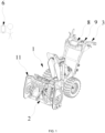
FIG. 1 is a structural view of a snow thrower according to the present application; -
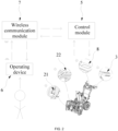
FIG. 2 is a structural diagram of a connection between an operating device and a wireless communication module according to the present application; -
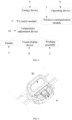
FIG. 3 is another structural diagram of a connection between an operating device and a wireless communication module according to the present application; -
FIG. 4 is a schematic diagram of operation logic of a snow thrower according to the present application; -
FIG. 5 is a structural view of a display screen according to the present application; -
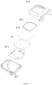
FIG. 6 is an exploded view of a display screen according to the present application; -
FIG. 7 is a structural view of a temperature adjustment device disposed on a rotating shaft according to the present application; and -
FIG. 8 is a circuit diagram of a control module, a temperature switch, and a temperature adjustment device of a snow thrower according to the present application. - Before any examples of this application are explained in detail, it is to be understood that this application is not limited to its application to the structural details and the arrangement of components set forth in the following description or illustrated in the above drawings.
- In this application, the terms "comprising", "including", "having" or any other variation thereof are intended to cover an inclusive inclusion such that a process, method, article or device comprising a series of elements includes not only those series of elements, but also other elements not expressly listed, or elements inherent in the process, method, article, or device. Without further limitations, an element defined by the phrase "comprising a ..." does not preclude the presence of additional identical elements in the process, method, article, or device comprising that element.
- In this application, the term "and/or" is a kind of association relationship describing the relationship between associated objects, which means that there can be three kinds of relationships. For example, A and/or B can indicate that A exists alone, A and B exist simultaneously, and B exists alone. In addition, the character "/" in this application generally indicates that the contextual associated objects belong to an "and/or" relationship.
- In this application, the terms "connection", "combination", "coupling" and "installation" may be direct connection, combination, coupling or installation, and may also be indirect connection, combination, coupling or installation. Among them, for example, direct connection means that two members or assemblies are connected together without intermediaries, and indirect connection means that two members or assemblies are respectively connected with at least one intermediate members and the two members or assemblies are connected by the at least one intermediate members. In addition, "connection" and "coupling" are not limited to physical or mechanical connections or couplings, and may include electrical connections or couplings.
- In this application, it is to be understood by those skilled in the art that a relative term (such as "about", "approximately", and "substantially") used in conjunction with quantity or condition includes a stated value and has a meaning dictated by the context. For example, the relative term includes at least a degree of error associated with the measurement of a particular value, a tolerance caused by manufacturing, assembly, and use associated with the particular value, and the like. Such relative term should also be considered as disclosing the range defined by the absolute values of the two endpoints. The relative term may refer to plus or minus of a certain percentage (such as 1%, 5%, 10%, or more) of an indicated value. A value that did not use the relative term should also be disclosed as a particular value with a tolerance. In addition, "substantially" when expressing a relative angular position relationship (for example, substantially parallel, substantially perpendicular), may refer to adding or subtracting a certain degree (such as 1 degree, 5 degrees, 10 degrees or more) to the indicated angle.
- In this application, those skilled in the art will understand that a function performed by an assembly may be performed by one assembly, multiple assemblies, one member, or multiple members. Likewise, a function performed by a member may be performed by one member, an assembly, or a combination of members.
- In this application, the terms "up", "down", "left", "right", "front", and "rear" " and other directional words are described based on the orientation or positional relationship shown in the drawings, and should not be understood as limitations to the examples of this application. In addition, in this context, it also needs to be understood that when it is mentioned that an element is connected "above" or "under" another element, it can not only be directly connected "above" or "under" the other element, but can also be indirectly connected "above" or "under" the other element through an intermediate element. It should also be understood that orientation words such as upper side, lower side, left side, right side, front side, and rear side do not only represent perfect orientations, but can also be understood as lateral orientations. For example, lower side may include directly below, bottom left, bottom right, front bottom, and rear bottom.
- In this application, the terms "controller", "processor", "central processor", "CPU" and "MCU" are interchangeable. Where a unit "controller", "processor", "central processing", "CPU", or "MCU" is used to perform a specific function, the specific function may be implemented by a single aforementioned unit or a plurality of the aforementioned unit.
- In this application, the term "device", "module" or "unit" may be implemented in the form of hardware or software to achieve specific functions.
- In this application, the terms "computing", "judging", "controlling", "determining", "recognizing" and the like refer to the operations and processes of a computer system or similar electronic computing device (e.g., controller, processor, etc.).
- As shown in
FIGS. 1 to 4 , a snow thrower includes a body 1, ahandle 3, anenergy device 4, acontrol module 5, and anoperating device 6. - The body 1 includes a
body housing 11 and a workingassembly 2. The workingassembly 2 includes anauger 22 and a snow sweeping motor (not shown in the figures) that drives theauger 22. The snow sweeping motor is accommodated in thebody housing 11 of the snow thrower. Theauger 22 is a functional component of the snow thrower and used for sweeping snow on the ground. The workingassembly 2 further includes arotating shaft 21, and two ends of therotating shaft 21 are rotatably connected to thebody housing 11 separately through connectors. Theauger 22 is mounted on therotating shaft 21, and the snow sweeping motor drives the rotatingshaft 21 to rotate and thus drives theauger 22 to rotate to sweep the snow on the ground. A connector may be a bearing, an inner ring of the bearing is connected to therotating shaft 21, and an outer ring of the bearing is connected to thebody housing 11. Thehandle 3 is for a user to hold and connected to the body 1. In a traveling direction of the snow thrower, thehandle 3 is disposed behind the body 1, and thehandle 3 is held to control the traveling direction of the snow thrower. - The
energy device 4 provides the snow thrower with electrical energy. In some examples, theenergy device 4 includes at least one battery pack, and the battery pack includes lithium cells disposed inside a housing of the battery pack and for storing electrical energy. Thebody housing 11 is formed with a battery compartment, and at least part of the battery pack is mounted in the battery compartment. - The
control module 5 has a power-on state for being powered by theenergy device 4 and is configured to control at least the operation of a walking motor and the snow sweeping motor of the snow thrower. Thecontrol module 5 includes a single-chip microcomputer or a microcontroller unit (MCU). In some examples, the single-chip microcomputer is an Advanced reduced instruction set computer (RISC) Machine (ARM) chip, and the MCU is a general-purpose digital signal processor (DSP) chip. In this example, thecontrol module 5 is disposed on thehandle 3. In some examples, thecontrol module 5 is disposed on the body 1. - As shown in
FIGS. 2 and3 , the operatingdevice 6 is configured to be operated by the user to send a temperature control signal to awireless communication module 7 when separated from the snow thrower, and thewireless communication module 7 is configured to transmit the temperature control signal to thecontrol module 5. Thecontrol module 5 is switched to the power-on state according to the temperature control signal, and thecontrol module 5 in the power-on state controls the temperature of at least part of the snow thrower. The operatingdevice 6 sends the temperature control signal to thewireless communication module 7, thewireless communication module 7 transmits the temperature control signal to thecontrol module 5, and thecontrol module 5 is switchable to the power-on state according to the temperature control signal and controls the temperature of at least part of the snow thrower so that a to-be-heated part of the snow thrower is pre-heated remotely, and the user does not need to wait outdoors, thereby reducing a time for which the user works outdoors and facilitating use. The temperature control signal may be directly forwarded by thewireless communication module 7 to thecontrol module 5 or may be sent to thecontrol module 5 after being processed by thewireless communication module 7, which is not limited here as long as the temperature control signal enables the user to remotely control the temperature of part of the snow thrower to increase or decrease. In some examples, the operatingdevice 6 may be disposed on the snow thrower or separated from the snow thrower. The user may control the temperature of at least part of the snow thrower at a short distance and/or at a long distance through the operatingdevice 6. - In some examples, the snow thrower further includes a
visual display device 8 and abutton assembly 9, where thevisual display device 8 and thebutton assembly 9 are disposed on the body 1 or thehandle 3. Thevisual display device 8 is configured to display some information about a working state of the snow thrower, making it easier for the user to learn the working state of the snow thrower in time. Thebutton assembly 9 includes functional operating members such as a power switch, a self-moving trigger, and a start-up trigger. - When the
control module 5 is in the power-on state, the temperature of one or more of thevisual display device 8, thebutton assembly 9, thehandle 3, and the workingassembly 2 is controlled through the operatingdevice 6, so as to prevent the above parts from freezing that affects the normal operation of the snow thrower. Moreover, the pre-heating of the above parts can be remotely controlled through the operatingdevice 6, and the user does not need to wait outdoors, thereby shortening the time for which the user works outdoors. - In some other examples, the heating is not limited to the
visual display device 8, thebutton assembly 9, thehandle 3, and the workingassembly 2 of the snow thrower, and other parts of the snow thrower that are likely to freeze or fog may also be heated, which is not specifically limited here. - The snow thrower further includes a
temperature adjustment device 10, thetemperature adjustment device 10 is separately disposed on one or more of at least part of thevisual display device 8, at least part of thebutton assembly 9, at least part of thehandle 3, and at least part of the workingassembly 2, and thecontrol module 5 is configured to control the temperature of thetemperature adjustment device 10. After theoperating device 6 sends the temperature control signal to thewireless communication module 7, thewireless communication module 7 transmits the temperature control signal to thecontrol module 5, and thecontrol module 5 controls the temperature of thetemperature adjustment device 10 to be the temperature set by the user through the operatingdevice 6. In this manner, the user adjusts the temperature of at least part of the snow thrower by adjusting the temperature of thetemperature adjustment device 10. Thetemperature adjustment device 10 may be a heating wire, or the temperature may be adjusted in one or more manners of electromagnetic heating, electric resistance heating, infrared light heating, and airstream flowing, which is not specifically limited here. In this example, thetemperature adjustment device 10 is the heating wire, and the heating wire is wound round part of thehandle 3. - In some examples, as shown in
FIGS. 5 and6 , thevisual display device 8 includes adisplay screen 81 configured to display information. The temperature of at least part of thevisual display device 8 is adjustable, that is, the precedingtemperature adjustment device 10 may be added on the outer side or the inner side of thevisual display device 8 to heat thevisual display device 8, so as to prevent thevisual display device 8 from lagging in a cold environment and effectively prevent thedisplay screen 81 from fogging that affects the viewing of information by the user. In this example, thevisual display device 8 is disposed on the handle. In some examples, thevisual display device 8 is disposed on the body 1. - The
display screen 81 includes adisplay housing 811, a window is disposed on a side of thedisplay housing 811, and a light-transmissive board 812 is disposed at the window. The light-transmissive board 812 prevents water and dust from entering thedisplay housing 811 and is basically transparent so that the user can observe, through the light-transmissive board 812, data and images displayed on thedisplay screen 81. - The
control module 5 includes a printed circuit board (PCB) 814. Adata board 813 and thePCB 814 are disposed in thedisplay housing 811. Thetemperature adjustment device 10 is further disposed in thedisplay housing 811. Thetemperature adjustment device 10 can increase the temperature in thedisplay housing 811 and heat thedata board 813, thePCB 814, and the light-transmissive board 812, so as to prevent the light-transmissive board 812 from fogging that affects the viewing of the display information by the user and prevent thedisplay screen 81 from lagging. In some examples, thePCB 814 may be disposed at other positions. - In some examples, as shown in
FIG. 7 , the temperature of at least part of the workingassembly 2 is adjustable, so as to prevent the workingassembly 2 from freezing in the cold environment, which affects the normal use of the snow thrower. - The rotating
shaft 21 is connected to thebody housing 11 and theauger 22. The temperature of at least part of therotating shaft 21 is adjustable, so as to prevent therotating shaft 21 from freezing that affects the normal operation of theauger 22. The two ends of therotating shaft 21 are connected to thebody housing 11 separately through the connectors. To ensure that the rotatingshaft 21 can rotate normally at a low temperature, the temperature of the connector is configured to be adjustable. In some examples, thetemperature adjustment device 10 is disposed on the connector to adjust the temperature of the connector. In some examples, the connector is the bearing, and thetemperature adjustment device 10 is disposed on the bearing. - The temperature of at least part of the
auger 22 is adjustable. After use of the snow thrower, snow attached to theauger 22 is prevented from freezing in the cold environment, which affects the next use. In some examples, thetemperature adjustment device 10 is disposed on a part of theauger 22 where snow is easily accumulated, so as to heat the snow on theauger 22 and prevent freezing. - The preceding
operating device 6 sends the control signal to thecontrol module 5 through thewireless communication module 7. In some examples, still referring toFIG. 2 , thewireless communication module 7 includes a Wi-Fi unit, and theoperating device 6 sends the temperature control signal to thecontrol module 5 through the Wi-Fi unit, thereby implementing a wireless communication connection between the operatingdevice 6 and thecontrol module 5. - Referring to
FIG. 3 , thewireless communication module 7 includes a Bluetooth unit, and theoperating device 6 sends the temperature control signal to thecontrol module 5 through the Bluetooth unit, so as to implement a wireless communication connection between the operatingdevice 6 and thecontrol module 5. - In some other examples, the
wireless communication module 7 includes the Wi-Fi unit and the Bluetooth unit, and theoperating device 6 may send the temperature control signal to thecontrol module 5 through any one of the Wi-Fi unit and the Bluetooth unit, so as to increase selectivity of a wireless connection between the operatingdevice 6 and thecontrol module 5. - The operating
device 6 sends the temperature control signal to thecontrol module 5 through thewireless communication module 7. In some other examples, the operatingdevice 6 may send, through thewireless communication module 7 and to thecontrol module 5, control signals for controlling components such as the snow sweeping motor and the walking motor or a control signal for adjusting a working mode of the snow thrower. - The operating
device 6 may be a remote control or a smart device such as a mobile phone, a smart watch, a tablet computer, or a computer. The operatingdevice 6 may be mounted on the body 1 of the snow thrower. The operatingdevice 6 has a matching key. Pressing the matching key may enable pairing and connection with thecontrol module 5 of the snow thrower so that the corresponding operation control is performed on the snow thrower. - Referring to
FIG. 4 , the precedingcontrol module 5 may control thetemperature adjustment device 10 to heat a component provided with thetemperature adjustment device 10, such as thehandle 3, thevisual display device 8, and the workingassembly 2. Thecontrol module 5 performs information exchange with thewireless communication module 7, and theoperating device 6 sends signals to thewireless communication module 7. Theenergy device 4 powers thecontrol module 5, and theenergy device 4 can also power thewireless communication module 7. When theenergy device 4 is mounted on the snow thrower but the entire machine is not powered on, thecontrol module 5 is not powered by theenergy device 4, and the snow thrower is in a standby state. That is to say, when the snow thrower is in the standby state, theenergy device 4 is connected to the snow thrower but does not power parts of the snow thrower excluding thewireless communication module 7. Only thewireless communication module 7 is always in a power-on state to receive an instruction sent by the user, thereby reducing energy consumption. In the standby state, theenergy device 4 powers only thewireless communication module 7 to maintain the normal operation of thewireless communication module 7. In this case, thewireless communication module 7 has low energy consumption and can receive, at any time, a signal sent by the operatingdevice 6. After receiving the signal sent by the operatingdevice 6, thewireless communication module 7 wakes up theenergy device 4 through thecontrol module 5 so that the parts of the snow thrower excluding thewireless communication module 7 are powered on, thereby achieving convenience, low energy consumption, and environmental friendliness. Thecontrol module 5 includes a step-down module. The step-down module is disposed on thePCB 814. Theenergy device 4 powers at least part of thewireless communication module 7 through the step-down module. The step-down module may reduce a voltage provided by theenergy device 4 to a voltage required by thewireless communication module 7. In some examples, the step-down module reduces a voltage of 60 V, 56 V, 48 V, or 40 V, etc. to 5 V, 3.3 V, 2.5 V, or 1.8 V, etc. - In some examples, the
wireless communication module 7 may be powered by a separate second energy device such as a button cell or a dry cell so that thewireless communication module 7 is always in the power-on state. - As shown in
FIG. 8 , thecontrol module 5 includes aswitchboard 12 and abattery management system 13. The user operates theoperating device 6 and sends the signal to thewireless communication module 7 remotely. After receiving the signal sent by the operatingdevice 6, thewireless communication module 7 sends a signal to theswitchboard 12. Theswitchboard 12 grounds an enable pin of thebattery management system 13 through an EIA-485 communication protocol or another communication protocol. Thebattery management system 13 is activated and the snow thrower is powered. Thecontrol module 5 controls the temperature of part of the snow thrower to change. In this manner, the temperature of part of the snow thrower is adjusted. - In this example, a control process for heating the
handle 3 is described below. The user operates theoperating device 6 and sends the signal to thewireless communication module 7. Thewireless communication module 7 sends the signal to theswitchboard 12. Theswitchboard 12 activates thebattery management system 13, and thebattery management system 13 makes thePCB 814 powered on. ThePCB 814 converts a large voltage provided by theenergy device 4 into a small voltage through the step-down module and increases the temperature of thetemperature adjustment device 10. The snow thrower includes afirst temperature sensor 14. Thefirst temperature sensor 14 is disposed on theswitchboard 12. Thefirst temperature sensor 14 detects an ambient temperature, and the control signal is sent to the PCB according to the detected ambient temperature. When the temperature is relatively low, thePCB 814 controls thetemperature adjustment device 10 heated with relatively large heating power. When the temperature is relatively high, thePCB 814 makes thetemperature adjustment device 10 heated with relatively small heating power. In this example, the heating power includes P1, P2, P3, and P4, where P1 > P2 > P3 > P4. When the temperature is lower than -10 °C, the heating power is P1. When the temperature is higher than or equal to -10 °C and lower than 0 °C, the heating power is P2. When the temperature is higher than or equal to 0 °C and lower than 15 °C, the heating power is P3. When the temperature is higher than or equal to 15 °C, the heating power is P4. Thecontrol module 5 includes the temperature sensor for detecting the temperature, thereby improving heating efficiency and saving energy. - The snow thrower includes a
temperature switch 15. Thetemperature switch 15 is disposed in a circuit of thetemperature adjustment device 10. Thetemperature switch 15 detects the temperature of thetemperature adjustment device 10 and controls, according to the temperature of thetemperature adjustment device 10, the circuit to be connected or disconnected. When the temperature of thetemperature adjustment device 10 is higher than a preset temperature, thetemperature switch 15 turns off. When the temperature of thetemperature adjustment device 10 is higher than 50 °C, thetemperature switch 15 turns off, and thetemperature adjustment device 10 is no longer heated. In some examples, the preset temperature is higher than or equal to 30 °C and lower than or equal to 70 °C. When the temperature of thetemperature adjustment device 10 is higher than 40 °C, thetemperature switch 15 turns off, and thetemperature adjustment device 10 is no longer heated. In some examples, when the temperature of thetemperature adjustment device 10 is higher than 30 °C, thetemperature switch 15 turns off, and thetemperature adjustment device 10 is no longer heated. In some examples, when the temperature of thetemperature adjustment device 10 is higher than 60 °C, thetemperature switch 15 turns off, and thetemperature adjustment device 10 is no longer heated. In some examples, when the temperature of thetemperature adjustment device 10 is higher than 70 °C, thetemperature switch 15 turns off, and thetemperature adjustment device 10 is no longer heated. In some examples, thetemperature switch 15 detects the temperature of thehandle 3. - In some examples, a second temperature sensor is disposed near the
temperature adjustment device 10. The second temperature sensor is connected to theswitchboard 12 or thePCB 814 and detects the temperature of thetemperature adjustment device 10. When the second temperature sensor detects that the temperature near thetemperature adjustment device 10 is higher than 50 °C, thePCB 814 stops the power supply to thetemperature adjustment device 10. A maximum heating temperature is set for thetemperature adjustment device 10 through thetemperature switch 15 or the second temperature sensor, thereby improving safety and preventing the user from being scalded. - The basic principles, main features, and advantages of the present application are shown and described above. It is to be understood by those skilled in the art that the preceding examples do not limit the present application in any form, and all technical solutions obtained through equivalent substitutions or equivalent transformations fall within the scope of the present application.
Claims (15)
- A snow thrower, comprising:a body (1) comprising a working assembly (2);a handle (3) for a user to hold and connected to the body; andan energy device (4) for providing the snow thrower with electrical energy;wherein the snow thrower further comprises:a control module (5) having a power-on state for being powered by the energy device;an operating device (6) configured to be operated by the user to send a temperature control signal to a wireless communication module (7) when separated from the snow thrower; andthe wireless communication module configured to transmit the temperature control signal to the control module;wherein the control module is switched to the power-on state according to the temperature control signal, and the control module in the power-on state controls a temperature of at least part of the snow thrower.
- The snow thrower of claim 1, further comprising a visual display device (8) and a button assembly (9), wherein the visual display device and the button assembly are disposed on the body or the handle, and a temperature of at least one of the visual display device, the button assembly, the handle, and the working assembly is configured to be controlled through the operating device.
- The snow thrower of claim 1, further comprising a temperature adjustment device (10), wherein the control module is configured to control a temperature of the temperature adjustment device to control the temperature of at least part of the snow thrower.
- The snow thrower of claim 3, wherein the temperature adjustment device is disposed on at least part of the snow thrower.
- The snow thrower of claim 1, wherein the wireless communication module comprises a Bluetooth unit and/or a Wi-Fi unit, and the operating device sends the temperature control signal to the wireless communication module through the Bluetooth unit and/or the Wi-Fi unit.
- The snow thrower of claim 1, wherein the energy device is further configured to power at least part of the wireless communication module.
- The snow thrower of claim 6, wherein the control module comprises a step-down module, and the energy device powers at least part of the wireless communication module through the step-down module.
- The snow thrower of claim 1, wherein the wireless communication module is disposed on the snow thrower.
- The snow thrower of claim 8, further comprising a second energy device configured to power the wireless communication module separately.
- The snow thrower of claim 1, further comprising a first temperature sensor (14) configured to detect an ambient temperature.
- The snow thrower of claim 10, wherein the control module controls the temperature of at least part of the snow thrower with different power according to the ambient temperature detected by the first temperature sensor.
- The snow thrower of claim 3, further comprising a temperature switch (15) configured to detect the temperature of the temperature adjustment device.
- The snow thrower of claim 12, wherein the temperature switch turns off when detecting that the temperature of the temperature adjustment device is higher than a preset temperature.
- The snow thrower of claim 13, wherein the preset temperature is higher than or equal to 30 °C and lower than or equal to 70 °C.
- The snow thrower of claim 3, wherein the temperature adjustment device is wound round part of the handle.
Applications Claiming Priority (3)
| Application Number | Priority Date | Filing Date | Title |
|---|---|---|---|
| CN202310794738 | 2023-06-29 | ||
| CN202420651273.1U CN222594714U (en) | 2023-06-29 | 2024-03-29 | Snow sweeper |
| CN202410381567.1A CN119221413A (en) | 2023-06-29 | 2024-03-29 | Snow sweeper |
Publications (2)
| Publication Number | Publication Date |
|---|---|
| EP4484647A1 true EP4484647A1 (en) | 2025-01-01 |
| EP4484647B1 EP4484647B1 (en) | 2025-11-26 |
Family
ID=91076558
Family Applications (1)
| Application Number | Title | Priority Date | Filing Date |
|---|---|---|---|
| EP24175316.9A Active EP4484647B1 (en) | 2023-06-29 | 2024-05-13 | Snow thrower |
Country Status (2)
| Country | Link |
|---|---|
| US (1) | US20250003163A1 (en) |
| EP (1) | EP4484647B1 (en) |
Citations (4)
| Publication number | Priority date | Publication date | Assignee | Title |
|---|---|---|---|---|
| WO2017207823A1 (en) * | 2016-06-03 | 2017-12-07 | The Kobi Company | Snow removal equipment |
| DE102018218877A1 (en) * | 2017-11-06 | 2019-05-09 | Harley-Davidson Motor Company Group, LLC | Heated handles for a motorcycle |
| WO2019118897A1 (en) * | 2017-12-14 | 2019-06-20 | Towers Kevin P | Remote controlled hybrid snow thrower |
| WO2023045496A1 (en) * | 2021-09-22 | 2023-03-30 | 南京泉峰科技有限公司 | Power tool, handle system suitable for power tool, and snow sweeper |
-
2024
- 2024-05-13 EP EP24175316.9A patent/EP4484647B1/en active Active
- 2024-05-20 US US18/669,192 patent/US20250003163A1/en active Pending
Patent Citations (4)
| Publication number | Priority date | Publication date | Assignee | Title |
|---|---|---|---|---|
| WO2017207823A1 (en) * | 2016-06-03 | 2017-12-07 | The Kobi Company | Snow removal equipment |
| DE102018218877A1 (en) * | 2017-11-06 | 2019-05-09 | Harley-Davidson Motor Company Group, LLC | Heated handles for a motorcycle |
| WO2019118897A1 (en) * | 2017-12-14 | 2019-06-20 | Towers Kevin P | Remote controlled hybrid snow thrower |
| WO2023045496A1 (en) * | 2021-09-22 | 2023-03-30 | 南京泉峰科技有限公司 | Power tool, handle system suitable for power tool, and snow sweeper |
Also Published As
| Publication number | Publication date |
|---|---|
| US20250003163A1 (en) | 2025-01-02 |
| EP4484647B1 (en) | 2025-11-26 |
Similar Documents
| Publication | Publication Date | Title |
|---|---|---|
| US7994654B2 (en) | Wireless-controlled power-saving apparatus | |
| US8139032B2 (en) | Power-saving computer mouse | |
| CN205722369U (en) | A kind of Intelligent home remote controller | |
| US20250003163A1 (en) | Snow thrower | |
| CN204645771U (en) | Low-power consumption self-action intelligent space lock | |
| WO2024032318A1 (en) | Electronic combination, battery pack, and electric tool and charging control method therefor | |
| CN202582607U (en) | Greenhouse canopy environmental monitoring device | |
| CN222594714U (en) | Snow sweeper | |
| HK1251083A1 (en) | Novel intelligent remote controllable battery system | |
| US12467617B2 (en) | Externally controlled indicator | |
| CN204759710U (en) | Site environment parameter monitoring module based on zigBee wireless LAN | |
| CN218715911U (en) | WIFI intelligence lock | |
| CN104898516A (en) | Portable oven control system based on singlechip | |
| CN218037756U (en) | Intelligent handheld terminal control circuit | |
| CN205899492U (en) | System power supply on -off controller based on computer data transmission interface on -line monitoring | |
| CN215646982U (en) | Low-power consumption camera based on all-in-one chip | |
| CN104599476B (en) | A kind of telepilot | |
| CN212572160U (en) | Charging device, charging station and mowing system | |
| CN207398511U (en) | A kind of intelligent standby power-saving jack | |
| CN209882125U (en) | Electric blanket controller with wireless charging function | |
| CN202166960U (en) | Power intelligent monitoring device | |
| CN207718615U (en) | Remote control terminal based on Zigbee module and Wi-Fi module | |
| CN223121983U (en) | A pot inspection control device and a heating furnace | |
| CN219913495U (en) | Intelligent radar sensing power-off device and electric water heater using same | |
| CN106406184A (en) | Built-in wireless communication and automatic detection and alarm relay module |
Legal Events
| Date | Code | Title | Description |
|---|---|---|---|
| PUAI | Public reference made under article 153(3) epc to a published international application that has entered the european phase |
Free format text: ORIGINAL CODE: 0009012 |
|
| STAA | Information on the status of an ep patent application or granted ep patent |
Free format text: STATUS: THE APPLICATION HAS BEEN PUBLISHED |
|
| AK | Designated contracting states |
Kind code of ref document: A1 Designated state(s): AL AT BE BG CH CY CZ DE DK EE ES FI FR GB GR HR HU IE IS IT LI LT LU LV MC ME MK MT NL NO PL PT RO RS SE SI SK SM TR |
|
| STAA | Information on the status of an ep patent application or granted ep patent |
Free format text: STATUS: REQUEST FOR EXAMINATION WAS MADE |
|
| STAA | Information on the status of an ep patent application or granted ep patent |
Free format text: STATUS: EXAMINATION IS IN PROGRESS |
|
| 17P | Request for examination filed |
Effective date: 20250513 |
|
| 17Q | First examination report despatched |
Effective date: 20250605 |
|
| GRAP | Despatch of communication of intention to grant a patent |
Free format text: ORIGINAL CODE: EPIDOSNIGR1 |
|
| STAA | Information on the status of an ep patent application or granted ep patent |
Free format text: STATUS: GRANT OF PATENT IS INTENDED |
|
| GRAS | Grant fee paid |
Free format text: ORIGINAL CODE: EPIDOSNIGR3 |
|
| GRAA | (expected) grant |
Free format text: ORIGINAL CODE: 0009210 |
|
| STAA | Information on the status of an ep patent application or granted ep patent |
Free format text: STATUS: THE PATENT HAS BEEN GRANTED |
|
| INTG | Intention to grant announced |
Effective date: 20251015 |
|
| AK | Designated contracting states |
Kind code of ref document: B1 Designated state(s): AL AT BE BG CH CY CZ DE DK EE ES FI FR GB GR HR HU IE IS IT LI LT LU LV MC ME MK MT NL NO PL PT RO RS SE SI SK SM TR |
|
| REG | Reference to a national code |
Ref country code: CH Ref legal event code: F10 Free format text: ST27 STATUS EVENT CODE: U-0-0-F10-F00 (AS PROVIDED BY THE NATIONAL OFFICE) Effective date: 20251126 Ref country code: GB Ref legal event code: FG4D |
|
| REG | Reference to a national code |
Ref country code: IE Ref legal event code: FG4D |
|
| REG | Reference to a national code |
Ref country code: DE Ref legal event code: R096 Ref document number: 602024001390 Country of ref document: DE |
|
| REG | Reference to a national code |
Ref country code: NL Ref legal event code: MP Effective date: 20251126 |
|
| PG25 | Lapsed in a contracting state [announced via postgrant information from national office to epo] |
Ref country code: ES Free format text: LAPSE BECAUSE OF FAILURE TO SUBMIT A TRANSLATION OF THE DESCRIPTION OR TO PAY THE FEE WITHIN THE PRESCRIBED TIME-LIMIT Effective date: 20251126 |
|
| REG | Reference to a national code |
Ref country code: LT Ref legal event code: MG9D |
|
| PG25 | Lapsed in a contracting state [announced via postgrant information from national office to epo] |
Ref country code: NO Free format text: LAPSE BECAUSE OF FAILURE TO SUBMIT A TRANSLATION OF THE DESCRIPTION OR TO PAY THE FEE WITHIN THE PRESCRIBED TIME-LIMIT Effective date: 20260226 |
|
| PG25 | Lapsed in a contracting state [announced via postgrant information from national office to epo] |
Ref country code: FI Free format text: LAPSE BECAUSE OF FAILURE TO SUBMIT A TRANSLATION OF THE DESCRIPTION OR TO PAY THE FEE WITHIN THE PRESCRIBED TIME-LIMIT Effective date: 20251126 Ref country code: AT Free format text: LAPSE BECAUSE OF FAILURE TO SUBMIT A TRANSLATION OF THE DESCRIPTION OR TO PAY THE FEE WITHIN THE PRESCRIBED TIME-LIMIT Effective date: 20251126 Ref country code: HR Free format text: LAPSE BECAUSE OF FAILURE TO SUBMIT A TRANSLATION OF THE DESCRIPTION OR TO PAY THE FEE WITHIN THE PRESCRIBED TIME-LIMIT Effective date: 20251126 |
|
| REG | Reference to a national code |
Ref country code: AT Ref legal event code: MK05 Ref document number: 1861157 Country of ref document: AT Kind code of ref document: T Effective date: 20251126 |
|
| PG25 | Lapsed in a contracting state [announced via postgrant information from national office to epo] |
Ref country code: NL Free format text: LAPSE BECAUSE OF FAILURE TO SUBMIT A TRANSLATION OF THE DESCRIPTION OR TO PAY THE FEE WITHIN THE PRESCRIBED TIME-LIMIT Effective date: 20251126 |
|
| PG25 | Lapsed in a contracting state [announced via postgrant information from national office to epo] |
Ref country code: RS Free format text: LAPSE BECAUSE OF FAILURE TO SUBMIT A TRANSLATION OF THE DESCRIPTION OR TO PAY THE FEE WITHIN THE PRESCRIBED TIME-LIMIT Effective date: 20260226 |
|
| PG25 | Lapsed in a contracting state [announced via postgrant information from national office to epo] |
Ref country code: IS Free format text: LAPSE BECAUSE OF FAILURE TO SUBMIT A TRANSLATION OF THE DESCRIPTION OR TO PAY THE FEE WITHIN THE PRESCRIBED TIME-LIMIT Effective date: 20260326 |
|
| PG25 | Lapsed in a contracting state [announced via postgrant information from national office to epo] |
Ref country code: PT Free format text: LAPSE BECAUSE OF FAILURE TO SUBMIT A TRANSLATION OF THE DESCRIPTION OR TO PAY THE FEE WITHIN THE PRESCRIBED TIME-LIMIT Effective date: 20260326 |
|
| PG25 | Lapsed in a contracting state [announced via postgrant information from national office to epo] |
Ref country code: PL Free format text: LAPSE BECAUSE OF FAILURE TO SUBMIT A TRANSLATION OF THE DESCRIPTION OR TO PAY THE FEE WITHIN THE PRESCRIBED TIME-LIMIT Effective date: 20251126 |
|
| PG25 | Lapsed in a contracting state [announced via postgrant information from national office to epo] |
Ref country code: LV Free format text: LAPSE BECAUSE OF FAILURE TO SUBMIT A TRANSLATION OF THE DESCRIPTION OR TO PAY THE FEE WITHIN THE PRESCRIBED TIME-LIMIT Effective date: 20251126 |
|
| PG25 | Lapsed in a contracting state [announced via postgrant information from national office to epo] |
Ref country code: BG Free format text: LAPSE BECAUSE OF FAILURE TO SUBMIT A TRANSLATION OF THE DESCRIPTION OR TO PAY THE FEE WITHIN THE PRESCRIBED TIME-LIMIT Effective date: 20251126 |
|
| PG25 | Lapsed in a contracting state [announced via postgrant information from national office to epo] |
Ref country code: LT Free format text: LAPSE BECAUSE OF FAILURE TO SUBMIT A TRANSLATION OF THE DESCRIPTION OR TO PAY THE FEE WITHIN THE PRESCRIBED TIME-LIMIT Effective date: 20251126 |
|
| PG25 | Lapsed in a contracting state [announced via postgrant information from national office to epo] |
Ref country code: SM Free format text: LAPSE BECAUSE OF FAILURE TO SUBMIT A TRANSLATION OF THE DESCRIPTION OR TO PAY THE FEE WITHIN THE PRESCRIBED TIME-LIMIT Effective date: 20251126 |
|
| PG25 | Lapsed in a contracting state [announced via postgrant information from national office to epo] |
Ref country code: DK Free format text: LAPSE BECAUSE OF FAILURE TO SUBMIT A TRANSLATION OF THE DESCRIPTION OR TO PAY THE FEE WITHIN THE PRESCRIBED TIME-LIMIT Effective date: 20251126 |
|
| PG25 | Lapsed in a contracting state [announced via postgrant information from national office to epo] |
Ref country code: IT Free format text: LAPSE BECAUSE OF FAILURE TO SUBMIT A TRANSLATION OF THE DESCRIPTION OR TO PAY THE FEE WITHIN THE PRESCRIBED TIME-LIMIT Effective date: 20251126 |
|
| PGFP | Annual fee paid to national office [announced via postgrant information from national office to epo] |
Ref country code: DE Payment date: 20260430 Year of fee payment: 3 |
|
| PG25 | Lapsed in a contracting state [announced via postgrant information from national office to epo] |
Ref country code: EE Free format text: LAPSE BECAUSE OF FAILURE TO SUBMIT A TRANSLATION OF THE DESCRIPTION OR TO PAY THE FEE WITHIN THE PRESCRIBED TIME-LIMIT Effective date: 20251126 |
|
| PG25 | Lapsed in a contracting state [announced via postgrant information from national office to epo] |
Ref country code: CZ Free format text: LAPSE BECAUSE OF FAILURE TO SUBMIT A TRANSLATION OF THE DESCRIPTION OR TO PAY THE FEE WITHIN THE PRESCRIBED TIME-LIMIT Effective date: 20251126 |
|
| PGFP | Annual fee paid to national office [announced via postgrant information from national office to epo] |
Ref country code: FR Payment date: 20260511 Year of fee payment: 3 |
|
| PG25 | Lapsed in a contracting state [announced via postgrant information from national office to epo] |
Ref country code: SK Free format text: LAPSE BECAUSE OF FAILURE TO SUBMIT A TRANSLATION OF THE DESCRIPTION OR TO PAY THE FEE WITHIN THE PRESCRIBED TIME-LIMIT Effective date: 20251126 |
|
| PG25 | Lapsed in a contracting state [announced via postgrant information from national office to epo] |
Ref country code: SE Free format text: LAPSE BECAUSE OF FAILURE TO SUBMIT A TRANSLATION OF THE DESCRIPTION OR TO PAY THE FEE WITHIN THE PRESCRIBED TIME-LIMIT Effective date: 20251126 |