EP4484641A2 - Horizontal pulper - Google Patents
Horizontal pulper Download PDFInfo
- Publication number
- EP4484641A2 EP4484641A2 EP24180463.2A EP24180463A EP4484641A2 EP 4484641 A2 EP4484641 A2 EP 4484641A2 EP 24180463 A EP24180463 A EP 24180463A EP 4484641 A2 EP4484641 A2 EP 4484641A2
- Authority
- EP
- European Patent Office
- Prior art keywords
- vat
- rotor
- horizontal
- side wall
- pulper
- Prior art date
- Legal status (The legal status is an assumption and is not a legal conclusion. Google has not performed a legal analysis and makes no representation as to the accuracy of the status listed.)
- Pending
Links
Images
Classifications
-
- D—TEXTILES; PAPER
- D21—PAPER-MAKING; PRODUCTION OF CELLULOSE
- D21B—FIBROUS RAW MATERIALS OR THEIR MECHANICAL TREATMENT
- D21B1/00—Fibrous raw materials or their mechanical treatment
- D21B1/04—Fibrous raw materials or their mechanical treatment by dividing raw materials into small particles, e.g. fibres
- D21B1/12—Fibrous raw materials or their mechanical treatment by dividing raw materials into small particles, e.g. fibres by wet methods, by the use of steam
- D21B1/30—Defibrating by other means
- D21B1/34—Kneading or mixing; Pulpers
- D21B1/345—Pulpers
-
- D—TEXTILES; PAPER
- D21—PAPER-MAKING; PRODUCTION OF CELLULOSE
- D21B—FIBROUS RAW MATERIALS OR THEIR MECHANICAL TREATMENT
- D21B1/00—Fibrous raw materials or their mechanical treatment
-
- D—TEXTILES; PAPER
- D21—PAPER-MAKING; PRODUCTION OF CELLULOSE
- D21B—FIBROUS RAW MATERIALS OR THEIR MECHANICAL TREATMENT
- D21B1/00—Fibrous raw materials or their mechanical treatment
- D21B1/04—Fibrous raw materials or their mechanical treatment by dividing raw materials into small particles, e.g. fibres
- D21B1/12—Fibrous raw materials or their mechanical treatment by dividing raw materials into small particles, e.g. fibres by wet methods, by the use of steam
- D21B1/30—Defibrating by other means
- D21B1/32—Defibrating by other means of waste paper
Definitions
- the present invention relates to horizontal pulpers, especially in connection with pulp and fiber web production. More especially the invention relates to a horizontal pulper according to the preamble part of claim 1.
- a typical production and treatment line comprises a forming section comprising a head box and a forming unit and a press section as well as a subsequent drying section and a reel-up.
- the production and treatment line can further comprise other devices and sections for finishing the fiber web, for example, a size press, a calender, a coating section.
- the production and treatment line also comprises typically at least one winder for forming customer rolls as well as a roll packaging apparatus.
- a treatment system of the fiber suspensions for example comprises a pulping section, a deashing system, a detrashing system, a coarse filtering section, a centrifugal cleaning section, a fractionation section, a fine filtering system, a fiber thickening system and fiber refining systems.
- fiber material is defibered to fiber pulp.
- horizontal pulpers the process is carried out so that a fiber suspension inside, i.e. in a vat, of the pulper is caused to a rotating flow by at least one rotor.
- the vat orientation is substantially horizontal or slightly inclined in longitudinal direction of the vat.
- the material to be defibered is thus, fed inside the pulper through the rotators, which break the fibers and feed the fiber suspension into the vat of the pulper to the rotating flow.
- the fiber suspension flow rises up in the vat and at some point, rotates back to the bottom of the vat and is defibered.
- the aim of pulping is to separate fibers from each other as well as possible, and/or to keeping size of possible different impurities in the fiber suspension, such as plastic, glues etc., as large as possible to facilitate their separation from fiber pulp.
- the rotor of the pulper is mounted to the pulper vat such that the centerline of rotation of the rotor is horizontal. This provides that the rotor has enough submergence depth in the vat. Thus, in cases, where mounting closer to the bottom of the vat is needed, this is usually accomplished by having a flat vat wall of the vat to mount the rotor on.
- a disadvantage of this known pulper vat design is that the flat wall of the vat sets up a, generally, more rectilinear structure, which is disadvantageous as it requires more stiffeners and may also portend a less efficient hydrodynamic vat shape as compared to a cylindrical vat design also known from prior art. In these vat designs however, the centerline of the rotation of the rotor is at 30 degrees off from horizontal, which creates potential problems in the mounting of the driving motor and other mechanical elements external to the vat, for example in view of space requirements.
- An object of the invention is to create a horizontal pulper, in which the disadvantages and problems of prior art pulper designs are eliminated or at least minimized.
- an object of the invention is to create a horizontal pulper with a lighter structure.
- an object of the invention is to create a horizontal pulper with an efficient hydrodynamic shape.
- an object of the invention is to create a horizontal pulper, in which the disadvantages and problems in the mounting of the driving motor and other mechanical elements external to the vat caused by the rotor mounting are eliminated or at least minimized.
- the horizontal pulper comprises a vat and at least one rotor, which has a cylindrical design extending from a first end to a second end, which vat has an open top part, a bottom part and side walls, and which vat comprises an opening on the side wall for the rotor, wherein the rotor is mounted to the opening on the side wall by a mounting collar such, that the center line of the rotor is horizontal.
- the mounting collar is conical and to the side wall attached mounting edge of the mounting collar is fitted to the curvilinear form of the side wall of the vat providing a tangential feed to the vat.
- the conical form of the mounting collar extends from the side wall of the vat outwards and is convergent from the side wall outwards. Further advantageously, the distance from the side wall to outer edge of the mounting collar and the diameter of the mounting collar vary depending on the size of the rotor to be mounted.
- the vat further comprises flow guides arranged inside the vat in vicinity of the rotor.
- two flow guides in vicinity of the rotor is provided two flow guides: a first flow guide and a second flow guide mounted at vicinity of the mounting edge of the mounting collar for the rotor, the first flow guide extends towards the bottom part of the vat and the second flow guide extends towards the top part of the vat.
- the flow guides have a curved form.
- the first end and the second end have a calotte form with dome-form outwards from the vat.
- fiber suspensions means liquids and suspensions, which contain fibers to be defibered and possible other occurring ingredients, which are meant to be filtered out.
- the fibers can be synthetic or non-synthetic fibers.
- the fibers in connection with pulp and fiber web production usually mean recycled cellulose fibers, but also newly produced cellulose fibers can come into question.
- the horizontal pulper according to the invention is suitable for different types of fiber suspensions of synthetic and/or non-synthetic fiber material.
- This new design having the cylindrical vat and horizontal rotor mounting provides thus lighter structure as less stiffeners are needed, and thus, production costs of the pulper are significantly decreased, due to the cylindrical form and efficient hydrodynamic vat shape due to the cylindrical form as well as easy and in view of space requirements of mounting of the driving motor and other mechanical elements external to the vat well-functioning structure due to the horizontal rotor mounting.
- the mounting collar of the rotor creates a tangential feed into the vat providing efficient hydrodynamic flow conditions.
- advantageous flow guides provided inside the vat improve the flow dynamics within the vat.
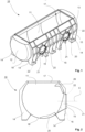
- FIG. 1 - 4 is schematically shown a pulper 10 comprising a vat 11.
- the pulper 10 is supported by support structures 14 on a floor or a corresponding base.
- the pulper 10 is a horizontal pulper and thus, orientation of the vat 11 is substantially horizontal or slightly inclined in longitudinal direction of the vat 11.
- the vat 11 has a cylindrical design, in which the cylindrical form extends from a first end 12 of the vat 11 to a second end 13 of the vat 11.
- the cylindrical design provides efficient hydrodynamic vat shape.
- the vat 11 comprises openings 20 for rotors 15 on a side wall 16 of the vat 11.
- the side wall 16 extends in the longitudinal direction of the vat 11 from the first end 12 to the second end 13.
- the side wall 16 is circular due to the cylindrical design of the vat 11.
- the side wall 16 is between the support structures 14 of the vat 11 and a top part 17 of the vat 11.
- the top part 17 is open and thus, the cylindrical form is cut at the top part 17 of the vat 11 by a horizontal plane.
- the rotors 15 are mounted to the side wall 16 at the openings 20 by mounting collars 21.
- the mounting collar 21 mounts the rotor 15 such, that center line C ( fig 2 ) of the rotor 15 is horizontal.
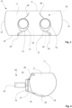
- a driving motor 30 ( fig. 4 ) and other external mechanical elements have well space.
- the mounting collar 21 is attached to the side wall 16 advantageously by welding.
- Form of the mounting collar 21 is conical and to the side wall 16 attached edge 22 is fitted to the curvilinear form of the side wall 16 of the vat 11 and thus, a tangential feed to the vat 11 is provided, which provides efficient hydrodynamic flow conditions for the fiber suspension flow inside the vat 11.
- the rotors 15 are thus separate units from the vat 11, which provides for a steady arrangements.
- the conical form of the mounting collar 21 extends from the side wall 16 of the vat 11 outwards and is convergent from the side wall 16 outwards. Further advantageously, the distance from the side wall 16 to outer edge of the mounting collar 21 and the diameter of the mounting collar 21 vary depending on the size of the rotor 15 to be mounted.
- the vat 11 also comprises inside arranged flow guides 25, 26 for intensify and guide the fiber suspension flow inside the vat 11 such, that possible "dead corners" and slowing effects are avoided.
- a first flow guide 25 and a second flow guide 26 In vicinity of each of the rotors 15 is provided two flow guides: a first flow guide 25 and a second flow guide 26.
- the flow guides 25, 26 are mounted at vicinity of the mounting edge 22 of the mounting collar 21 and comprise the first flow guides 25 extending towards a bottom part 18 of the vat 11 from the lower mounting edge 22 of the mounting collar 21 and the second flow guides 26 extending towards the top part 17 of the vat 11 from the upper mounting edge 22 of the mounting collar 21.
- the flow guides 25, 26 have a curved form.
- the curved forms of the first flow guides 25 is extend as a convex form from the mounting collar 21 towards the bottom part 18 and the curved forms of the second flow guides 26 extend as a concave form from the top part 17 towards the mounting collar 21.
- the flow guides 25, 26 are thus, correspondingly extending inclined.
- the flow guides 25, 26 are substantially planar flap-like parts and extend from the side wall 16 inside the vat 11.
- the flow guides 25, 26 are advantageously curved parts formed of plate-like material.
- the flow guides 25, 26 are configured to guide the flow towards or away from the rotor/- s 15.
- the first end 12 and the second end 13 have advantageously calotte form with dome-form outwards from the vat 11, which further improves strength of the vat 11 and further less stiffeners are needed.
- the rotor 15 is attached to a driving motor 30 for providing power for the rotating movement of the rotor 15.
Landscapes
- Engineering & Computer Science (AREA)
- Mechanical Engineering (AREA)
- Life Sciences & Earth Sciences (AREA)
- Wood Science & Technology (AREA)
- Paper (AREA)
Abstract
Description
- The present invention relates to horizontal pulpers, especially in connection with pulp and fiber web production. More especially the invention relates to a horizontal pulper according to the preamble part of claim 1.
- As known from the prior art in fiber web machines, especially in paper and board machines, the fiber web is produced and treated in an assembly formed by a number of apparatuses arranged consecutively in a process line. A typical production and treatment line comprises a forming section comprising a head box and a forming unit and a press section as well as a subsequent drying section and a reel-up. The production and treatment line can further comprise other devices and sections for finishing the fiber web, for example, a size press, a calender, a coating section. The production and treatment line also comprises typically at least one winder for forming customer rolls as well as a roll packaging apparatus.
- Before the head box fiber suspensions comprising recycled and/or virgin fibers are treated to be fed into the head box to be used to produce the fiber webs. A treatment system of the fiber suspensions for example comprises a pulping section, a deashing system, a detrashing system, a coarse filtering section, a centrifugal cleaning section, a fractionation section, a fine filtering system, a fiber thickening system and fiber refining systems.
- In pulpers fiber material is defibered to fiber pulp. In horizontal pulpers the process is carried out so that a fiber suspension inside, i.e. in a vat, of the pulper is caused to a rotating flow by at least one rotor. In horizontal pulpers the vat orientation is substantially horizontal or slightly inclined in longitudinal direction of the vat. The material to be defibered is thus, fed inside the pulper through the rotators, which break the fibers and feed the fiber suspension into the vat of the pulper to the rotating flow. During the rotating flow caused by the rotor/-s the fiber suspension flow rises up in the vat and at some point, rotates back to the bottom of the vat and is defibered. The aim of pulping is to separate fibers from each other as well as possible, and/or to keeping size of possible different impurities in the fiber suspension, such as plastic, glues etc., as large as possible to facilitate their separation from fiber pulp.
- In one type of known horizontal pulpers, the rotor of the pulper is mounted to the pulper vat such that the centerline of rotation of the rotor is horizontal. This provides that the rotor has enough submergence depth in the vat. Thus, in cases, where mounting closer to the bottom of the vat is needed, this is usually accomplished by having a flat vat wall of the vat to mount the rotor on. A disadvantage of this known pulper vat design is that the flat wall of the vat sets up a, generally, more rectilinear structure, which is disadvantageous as it requires more stiffeners and may also portend a less efficient hydrodynamic vat shape as compared to a cylindrical vat design also known from prior art. In these vat designs however, the centerline of the rotation of the rotor is at 30 degrees off from horizontal, which creates potential problems in the mounting of the driving motor and other mechanical elements external to the vat, for example in view of space requirements.
- An object of the invention is to create a horizontal pulper, in which the disadvantages and problems of prior art pulper designs are eliminated or at least minimized.
- In particular, an object of the invention is to create a horizontal pulper with a lighter structure.
- In particular, an object of the invention is to create a horizontal pulper with an efficient hydrodynamic shape.
- In particular, an object of the invention is to create a horizontal pulper, in which the disadvantages and problems in the mounting of the driving motor and other mechanical elements external to the vat caused by the rotor mounting are eliminated or at least minimized.
- In order to achieve the above objects and those that will come apparent later the horizontal pulper according to the invention is mainly characterized by the features of the characterizing part of the independent claim 1. Advantageous aspects and features of the invention are presented in the dependent claims.
- According to the invention the horizontal pulper comprises a vat and at least one rotor, which has a cylindrical design extending from a first end to a second end, which vat has an open top part, a bottom part and side walls, and which vat comprises an opening on the side wall for the rotor, wherein the rotor is mounted to the opening on the side wall by a mounting collar such, that the center line of the rotor is horizontal.
- According to the invention the mounting collar is conical and to the side wall attached mounting edge of the mounting collar is fitted to the curvilinear form of the side wall of the vat providing a tangential feed to the vat. Advantageously, the conical form of the mounting collar extends from the side wall of the vat outwards and is convergent from the side wall outwards. Further advantageously, the distance from the side wall to outer edge of the mounting collar and the diameter of the mounting collar vary depending on the size of the rotor to be mounted.
- According to an advantageous feature of the invention the vat further comprises flow guides arranged inside the vat in vicinity of the rotor.
- According to an advantageous feature of the invention in vicinity of the rotor is provided two flow guides: a first flow guide and a second flow guide mounted at vicinity of the mounting edge of the mounting collar for the rotor, the first flow guide extends towards the bottom part of the vat and the second flow guide extends towards the top part of the vat.
- According to an advantageous feature of the invention the flow guides have a curved form.
- According to an advantageous feature of the invention the first end and the second end have a calotte form with dome-form outwards from the vat.
- The term "fiber suspensions" means liquids and suspensions, which contain fibers to be defibered and possible other occurring ingredients, which are meant to be filtered out. The fibers can be synthetic or non-synthetic fibers.
- The fibers in connection with pulp and fiber web production usually mean recycled cellulose fibers, but also newly produced cellulose fibers can come into question. The horizontal pulper according to the invention is suitable for different types of fiber suspensions of synthetic and/or non-synthetic fiber material.
- By the invention and its advantageous features several advantages are achieved: This new design having the cylindrical vat and horizontal rotor mounting provides thus lighter structure as less stiffeners are needed, and thus, production costs of the pulper are significantly decreased, due to the cylindrical form and efficient hydrodynamic vat shape due to the cylindrical form as well as easy and in view of space requirements of mounting of the driving motor and other mechanical elements external to the vat well-functioning structure due to the horizontal rotor mounting. The mounting collar of the rotor creates a tangential feed into the vat providing efficient hydrodynamic flow conditions. Additionally, advantageous flow guides provided inside the vat improve the flow dynamics within the vat.
- Aspects of the invention, however, together with additional objects and advantages thereof, will be best understood from the following description of some example embodiments when read in connection with the accompanying drawings and in the following the invention is described in more detail referring to the accompanying drawing, in which
- In
figure 1 is schematically shown an example of a horizontal pulper as a perspective view. - In
figures 2 is schematically shown a cross-sectional cut view of the example offigure 1 . - In
figure 3 is schematically shown the example offigures 1-2 as a side view. - In
figure 4 is schematically shown another cross-sectional cut view of the example offigures 1 - 3 . - During the course of this description like numbers and signs will be used to identify like elements according to the different views which illustrate the invention. Repetition of some reference signs may have been omitted in the figures for clarity reasons.
- In
figures 1 - 4 is schematically shown apulper 10 comprising avat 11. Thepulper 10 is supported bysupport structures 14 on a floor or a corresponding base. Thepulper 10 is a horizontal pulper and thus, orientation of thevat 11 is substantially horizontal or slightly inclined in longitudinal direction of thevat 11. Thevat 11 has a cylindrical design, in which the cylindrical form extends from afirst end 12 of thevat 11 to asecond end 13 of thevat 11. The cylindrical design provides efficient hydrodynamic vat shape. Thevat 11 comprisesopenings 20 forrotors 15 on aside wall 16 of thevat 11. Theside wall 16 extends in the longitudinal direction of thevat 11 from thefirst end 12 to thesecond end 13. Theside wall 16 is circular due to the cylindrical design of thevat 11. Theside wall 16 is between thesupport structures 14 of thevat 11 and atop part 17 of thevat 11. Thetop part 17 is open and thus, the cylindrical form is cut at thetop part 17 of thevat 11 by a horizontal plane. Therotors 15 are mounted to theside wall 16 at theopenings 20 by mountingcollars 21. Themounting collar 21 mounts therotor 15 such, that center line C (fig 2 ) of therotor 15 is horizontal. Thus, a driving motor 30 (fig. 4 ) and other external mechanical elements have well space. The mountingcollar 21 is attached to theside wall 16 advantageously by welding. Form of the mountingcollar 21 is conical and to theside wall 16 attachededge 22 is fitted to the curvilinear form of theside wall 16 of thevat 11 and thus, a tangential feed to thevat 11 is provided, which provides efficient hydrodynamic flow conditions for the fiber suspension flow inside thevat 11. Therotors 15 are thus separate units from thevat 11, which provides for a steady arrangements. Advantageously, the conical form of the mountingcollar 21 extends from theside wall 16 of thevat 11 outwards and is convergent from theside wall 16 outwards. Further advantageously, the distance from theside wall 16 to outer edge of the mountingcollar 21 and the diameter of the mountingcollar 21 vary depending on the size of therotor 15 to be mounted. Thevat 11 also comprises inside arranged flow guides 25, 26 for intensify and guide the fiber suspension flow inside thevat 11 such, that possible "dead corners" and slowing effects are avoided. In vicinity of each of therotors 15 is provided two flow guides: afirst flow guide 25 and a second flow guide 26.The flow guides 25, 26 are mounted at vicinity of the mountingedge 22 of the mountingcollar 21 and comprise the first flow guides 25 extending towards abottom part 18 of thevat 11 from the lower mountingedge 22 of the mountingcollar 21 and the second flow guides 26 extending towards thetop part 17 of thevat 11 from the upper mountingedge 22 of the mountingcollar 21. The flow guides 25, 26 have a curved form. The curved forms of the first flow guides 25 is extend as a convex form from the mountingcollar 21 towards thebottom part 18 and the curved forms of the second flow guides 26 extend as a concave form from thetop part 17 towards the mountingcollar 21. The flow guides 25, 26 are thus, correspondingly extending inclined. The flow guides 25, 26 are substantially planar flap-like parts and extend from theside wall 16 inside thevat 11. Thus, the flow guides 25, 26 are advantageously curved parts formed of plate-like material. The flow guides 25, 26 are configured to guide the flow towards or away from the rotor/-s 15. Thefirst end 12 and thesecond end 13 have advantageously calotte form with dome-form outwards from thevat 11, which further improves strength of thevat 11 and further less stiffeners are needed. As shown infigure 4 therotor 15 is attached to a drivingmotor 30 for providing power for the rotating movement of therotor 15. - In the description in the foregoing, although some functions have been described with reference to certain features, those functions may be performable by other features whether described or not. Although features have been described with reference to certain embodiments or examples, those features may also be present in other embodiments or examples whether described or not. Above the invention has been described by referring to some advantageous examples only to which the invention is not to be narrowly limited. Many modifications and alterations are possible within the invention as defined in the following claims.
- Reference signs used in the drawing:
- 10 pulper
- 11 vat
- 12 first end of the vat
- 13 second end of the vat
- 14 support structure
- 15 rotor
- 16 side wall
- 17 top part of the vat
- 18 bottom part of the vat
- 20 opening for the rotor
- 21 mounting collar for the rotor
- 22 mounting edge of the mounting collar
- 25 first flow guide
- 26 second flow guide
- 30 drive motor
- C centerline of the rotor
Claims (5)
- Horizontal pulper (10) comprising a vat (11) and at least one rotor (15), which has a cylindrical design extending from a first end (12) to a second end (13) and which vat (11) has an open top part (17), a bottom part (18) and side walls (16), which vat (11) comprises an opening (20) on the side wall (16) for the rotor (15), which rotor (15) is mounted to the opening (20) on the side wall (16) by a mounting collar (21) such, that the center line (C) of the rotor (15) is horizontal, characterized in that the mounting collar (21) is conical and to the side wall (16) attached mounting edge (22) of the mounting collar (21) is fitted to the curvilinear form of the side wall (16) of the vat (11) providing a tangential feed to the vat (11).
- Horizontal pulper (10) according to claim 1, characterized in that the vat (11) further comprises flow guides (25, 26) arranged inside the vat in vicinity of the rotor (15).
- Horizontal pulper (10) according to claim 2, characterized in that in vicinity of the rotor is provided two flow guides: a first flow guide (25) and a second flow guide (26) mounted at vicinity of the mounting edge (22) of the mounting collar (21) for the rotor (15), that the first flow guide (25) extends towards the bottom part (18) of the vat (11) and the second flow guide (26) extends towards the top part (17) of the vat (11).
- Horizontal pulper (10) according to claim 2 or 3, characterized in that the flow guides (25, 26) have a curved form.
- Horizontal pulper (10) according to any of the previous claims, characterized in that the first end (12) and the second end (13) have a calotte form with dome-form outwards from the vat (11).
Applications Claiming Priority (1)
| Application Number | Priority Date | Filing Date | Title |
|---|---|---|---|
| US202363510168P | 2023-06-26 | 2023-06-26 |
Publications (2)
| Publication Number | Publication Date |
|---|---|
| EP4484641A2 true EP4484641A2 (en) | 2025-01-01 |
| EP4484641A3 EP4484641A3 (en) | 2025-06-04 |
Family
ID=91433199
Family Applications (1)
| Application Number | Title | Priority Date | Filing Date |
|---|---|---|---|
| EP24180463.2A Pending EP4484641A3 (en) | 2023-06-26 | 2024-06-06 | Horizontal pulper |
Country Status (2)
| Country | Link |
|---|---|
| EP (1) | EP4484641A3 (en) |
| FI (1) | FI131166B1 (en) |
Family Cites Families (3)
| Publication number | Priority date | Publication date | Assignee | Title |
|---|---|---|---|---|
| GB677787A (en) * | 1949-08-17 | 1952-08-20 | Millspaugh Ltd | Improvements in or relating to machines for breaking and mixing paper-making materials |
| NL140020B (en) * | 1968-06-21 | 1973-10-15 | Kobayashi Tadashi | DEVICE FOR PAPER RAW MATERIAL. |
| DE10138860A1 (en) * | 2001-08-08 | 2003-02-27 | Voith Paper Patent Gmbh | Process for guiding the suspension in a paper pulper as well as pulp solver for carrying out the process |
-
2023
- 2023-09-07 FI FI20235998A patent/FI131166B1/en active
-
2024
- 2024-06-06 EP EP24180463.2A patent/EP4484641A3/en active Pending
Also Published As
| Publication number | Publication date |
|---|---|
| FI131166B1 (en) | 2024-11-13 |
| EP4484641A3 (en) | 2025-06-04 |
| FI20235998A1 (en) | 2024-11-13 |
Similar Documents
| Publication | Publication Date | Title |
|---|---|---|
| US4880540A (en) | Pulp screening apparatus | |
| EP0473354B1 (en) | Apparatus for pressurised screening of a fibrous material liquid suspension | |
| EP0289020B1 (en) | Method and apparatus for treating fiber suspension | |
| US5108586A (en) | Flotation machine for deinking | |
| KR100538184B1 (en) | Apparatus and method of generating stock turbulence in a fourdrinier forming section | |
| US4619736A (en) | Apparatus for defiberizing, screening and pumping cellulose pulp or recycled paper | |
| EP4484641A2 (en) | Horizontal pulper | |
| CA2423775C (en) | Device for separating air from flotation foam | |
| US5176822A (en) | Flotation machine for deinking | |
| EP1184509B2 (en) | Screening apparatus for fiber suspension | |
| EP0294832B1 (en) | Pulp screening apparatus | |
| CA2397126A1 (en) | Process for guiding a suspension in a paper stock pulper and a paper stock pulper for conducting the process | |
| US20250198082A1 (en) | Pulper for producing a stock suspension from solid particles and a flowable medium | |
| US20060186235A1 (en) | Method for refining paper or cellulose fibers in an aqueous suspension | |
| FI131238B1 (en) | Drum of a drum pulper and a drum pulper | |
| CN111501393B (en) | Screening apparatus | |
| EP4575080A1 (en) | Disperger with a dilution system | |
| EP4644605B1 (en) | Pulper rotor | |
| US20030029584A1 (en) | Process for guiding a suspension in a paper stock pulper and a paper stock pulper for conducting the process | |
| US5051151A (en) | Side extraction pulper with screw type rotor | |
| US7735655B2 (en) | Screen and method for screening pulp | |
| EP3260596B1 (en) | Deashing system and deashing method | |
| EP4382186A1 (en) | Filter sector assembly of a disc filter | |
| EP4343056B1 (en) | Disperger | |
| EP3663462B1 (en) | A screening device and a rotor |
Legal Events
| Date | Code | Title | Description |
|---|---|---|---|
| PUAI | Public reference made under article 153(3) epc to a published international application that has entered the european phase |
Free format text: ORIGINAL CODE: 0009012 |
|
| STAA | Information on the status of an ep patent application or granted ep patent |
Free format text: STATUS: THE APPLICATION HAS BEEN PUBLISHED |
|
| AK | Designated contracting states |
Kind code of ref document: A2 Designated state(s): AL AT BE BG CH CY CZ DE DK EE ES FI FR GB GR HR HU IE IS IT LI LT LU LV MC ME MK MT NL NO PL PT RO RS SE SI SK SM TR |
|
| PUAL | Search report despatched |
Free format text: ORIGINAL CODE: 0009013 |
|
| AK | Designated contracting states |
Kind code of ref document: A3 Designated state(s): AL AT BE BG CH CY CZ DE DK EE ES FI FR GB GR HR HU IE IS IT LI LT LU LV MC ME MK MT NL NO PL PT RO RS SE SI SK SM TR |
|
| RIC1 | Information provided on ipc code assigned before grant |
Ipc: D21B 1/34 20060101ALI20250428BHEP Ipc: D21B 1/32 20060101AFI20250428BHEP |
|
| STAA | Information on the status of an ep patent application or granted ep patent |
Free format text: STATUS: REQUEST FOR EXAMINATION WAS MADE |
|
| 17P | Request for examination filed |
Effective date: 20251009 |