EP4484637A1 - Gas heating apparatus and gas clothes dryer - Google Patents
Gas heating apparatus and gas clothes dryer Download PDFInfo
- Publication number
- EP4484637A1 EP4484637A1 EP23758970.0A EP23758970A EP4484637A1 EP 4484637 A1 EP4484637 A1 EP 4484637A1 EP 23758970 A EP23758970 A EP 23758970A EP 4484637 A1 EP4484637 A1 EP 4484637A1
- Authority
- EP
- European Patent Office
- Prior art keywords
- gas
- groove
- connecting plate
- flow guide
- collecting chamber
- Prior art date
- Legal status (The legal status is an assumption and is not a legal conclusion. Google has not performed a legal analysis and makes no representation as to the accuracy of the status listed.)
- Withdrawn
Links
Images




Classifications
-
- F—MECHANICAL ENGINEERING; LIGHTING; HEATING; WEAPONS; BLASTING
- F23—COMBUSTION APPARATUS; COMBUSTION PROCESSES
- F23D—BURNERS
- F23D14/00—Burners for combustion of a gas, e.g. of a gas stored under pressure as a liquid
- F23D14/46—Details
- F23D14/84—Flame spreading or otherwise shaping
-
- D—TEXTILES; PAPER
- D06—TREATMENT OF TEXTILES OR THE LIKE; LAUNDERING; FLEXIBLE MATERIALS NOT OTHERWISE PROVIDED FOR
- D06F—LAUNDERING, DRYING, IRONING, PRESSING OR FOLDING TEXTILE ARTICLES
- D06F58/00—Domestic laundry dryers
- D06F58/20—General details of domestic laundry dryers
- D06F58/26—Heating arrangements, e.g. gas heating equipment
- D06F58/263—Gas heating equipment
-
- F—MECHANICAL ENGINEERING; LIGHTING; HEATING; WEAPONS; BLASTING
- F23—COMBUSTION APPARATUS; COMBUSTION PROCESSES
- F23D—BURNERS
- F23D14/00—Burners for combustion of a gas, e.g. of a gas stored under pressure as a liquid
- F23D14/02—Premix gas burners, i.e. in which gaseous fuel is mixed with combustion air upstream of the combustion zone
- F23D14/04—Premix gas burners, i.e. in which gaseous fuel is mixed with combustion air upstream of the combustion zone induction type, e.g. Bunsen burner
-
- F—MECHANICAL ENGINEERING; LIGHTING; HEATING; WEAPONS; BLASTING
- F23—COMBUSTION APPARATUS; COMBUSTION PROCESSES
- F23D—BURNERS
- F23D2207/00—Ignition devices associated with burner
Definitions
- Gas-fired clothes dryer uses the heat generated by gas combustion to heat air, and the heated dry hot air enters a clothes drying drum and contacts with wet clothes in the clothes drying drum, thereby drying the clothes.
- a gas-fired clothes dryer includes a housing, a clothes drying drum, a blower fan and a gas-fired heating device.
- the housing is internally provided with an accommodating space, and the clothes drying drum, the blower fan and the gas-fired heating device are all disposed in the accommodating space.
- the gas-fired heating device includes a burner, a combustion cylinder and an igniter. The igniter is disposed close to the burner.
- a spray head of the burner is hemispherical, and an axis of the hemispherical spray head is parallel to a horizontal plane.
- a plurality of nozzles are provided on the surface of the hemispherical spray head, and each of the nozzles faces a different direction.
- the spray head and the igniter are both accommodated in the combustion cylinder.
- the gas ejected from the spray head is ignited by the igniter, the heat generated by gas combustion heats the air in the combustion cylinder, and the heated air enters the clothes drying drum under the action of the blower fan to dry the clothes in the clothes drying drum.
- the main purpose of embodiments of the present application is to provide a gas-fired heating device and a gas-fired clothes dryer to solve the problem that a related gas-fired clothes dryer has low combustion efficiency of the gas.
- a gas-fired heating device including a burner and an igniter
- the burner includes a body and a gas collecting plate, the gas collecting plate is concave upwards to form a gas collecting chamber, and the body has a combustion end provided with a nozzle; the gas collecting plate is connected with the combustion end, and the gas collecting plate is located above the nozzle, so that gas ejected from the nozzle enters the gas collecting chamber; the igniter is provided with an ignition end located outside the nozzle, and the ignition end extends into the gas collecting chamber.
- the body includes a first connecting plate and a second connecting plate, the first connecting plate is attached to the second connecting plate, the first connecting plate is provided with a first groove, and the first groove is concave away from the second connecting plate; the second connecting plate is provided with a second groove, the second groove is concave away from the first connecting plate, the second groove is right opposite to the first groove, and a gas channel is formed by being enclosed by the second groove and the first groove; the nozzle is formed at one end of the gas channel close to the gas collecting chamber, an inlet port is formed at one end of the gas channel away from the gas collecting chamber, and the gas channel is connected with the gas collecting chamber through the nozzle.
- the first groove is provided with a first flow guide groove wall, the first flow guide groove wall is close to the gas collecting chamber, the first flow guide groove wall is disposed inclined relative to the first connecting plate, and a distance between the first flow guide groove wall and the inlet port increases from a groove bottom of the first groove to a groove opening of the first groove.
- the second groove is provided with a second flow guide groove wall, the second flow guide groove wall is close to the gas collecting chamber, the second flow guide groove wall is disposed inclined relative to the second connecting plate, and a distance between the second flow guide groove wall and the inlet port increases from a groove bottom of the second groove to a groove opening of the second groove.
- the gas collecting chamber includes a first side wall, a second side wall and a flow guide wall, the first side wall is perpendicular to the first connecting plate, and the first side wall is parallel to an axis of the gas channel; the second side wall and the first side wall are parallel and spaced apart from each other, and the first side wall and the second side wall are connected through the flow guide wall; the gas collecting chamber is formed by being enclosed by the first side wall, the second side wall and the flow guide wall, and one end of the flow guide wall close to the nozzle is connected with one end of the first flow guide groove wall close to the second connecting plate.
- a projection of the flow guide wall on a plane where the first side wall is located is in a circular arc shape.
- the second connecting plate is bent upward along two ends of an axis perpendicular to the gas channel to form bent plates, slots are formed by being enclosed by the bent plates and the second connecting plate, and the first connecting plate is embedded into the slots.
- the gas-fired heating device further includes a mounting bracket, and the burner and the igniter are both connected to the mounting bracket.
- Embodiments of the present application further provide a gas-fired clothes dryer, including the above gas-fired heating device.
- the gas-fired clothes dryer includes the gas-fired heating device and the gas-fired heating device includes the burner and the igniter, where the burner includes the body and the gas collecting plate, the gas collecting plate is concave upwards to form the gas collecting chamber, and the body has the combustion end provided with the nozzle; the gas collecting plate is connected with the combustion end, and the gas collecting plate is located above the nozzle, so that gas ejected from the nozzle enters the gas collecting chamber; the igniter is provided with the ignition end located outside the nozzle, and the ignition end extends into the gas collecting chamber.
- the gas ejected from the nozzle is firstly gathered in the gas collecting chamber, and the gas collecting chamber can prevent the gas ejected from the nozzle from escaping to reduce the escaping amount of the gas, so that the gas ejected from the nozzle can be ignited by the igniter as much as possible, thereby improving the combustion efficiency of the gas.
- connection may be a fixed connection, a detachable connection, or an integral connection; “connection” may be a mechanical connection or an electrical connection; “connection” may be a direct connection or an indirect connection through an intermediate medium; and “connection” may be the internal communication of two components.
- connection may be a fixed connection, a detachable connection, or an integral connection; “connection” may be a mechanical connection or an electrical connection; “connection” may be a direct connection or an indirect connection through an intermediate medium; and “connection” may be the internal communication of two components.
- a gas-fired clothes dryer in the related art includes a housing, a clothes drying drum, a blower fan and a gas-fired heating device.
- the housing is internally provided with an accommodating space, and the clothes drying drum, the blower fan and the gas-fired heating device are all disposed in the accommodating space.
- the gas-fired heating device includes a gas valve, an inlet tube, a burner, a combustion cylinder and an igniter.
- the gas valve is provided with an inlet port and an outlet port, the inlet port is connected with the inlet tube, and the outlet port is connected with the burner.
- the burner is provided with a combustion-supporting air inlet port and a spray head, the combustion-supporting air inlet port is used for enabling the combustion-supporting air to enter the inside of the burner, and the combustion-supporting air is mixed with the gas in the burner and then the mixed gas is ejected out from the spray head.
- the igniter is disposed close to the burner.
- the spray head and the igniter are both accommodated in the combustion cylinder.
- the gas ejected from the spray head is ignited by the igniter, the heat generated by gas combustion heats the air in the combustion cylinder, and the heated air enters the clothes drying drum under the action of the blower fan to dry the clothes in the clothes drying drum.
- the spray head of the burner is generally hemispherical, and an axis of the hemispherical spray head is parallel to a horizontal plane.
- a plurality of nozzles are provided on the surface of the hemispherical spray head, and each of the nozzles faces a different direction. The gas is ejected from the nozzles.
- the gas ejected from the nozzles close to the igniter is easy to be ignited, while the gas ejected from the nozzles away from the igniter is difficult to be ignited by the igniter due to the long distance from the igniter and is easy to directly escape into the combustion cylinder without combustion, so that the gas ejected from the nozzles is not fully combusted, resulting in a decrease in the combustion efficiency of the gas and a waste of gas energy.
- Embodiments of the present application provide a gas-fired heating device and a gas-fired clothes dryer, where a gas collecting chamber is disposed outside a nozzle of a burner, and an ignition end of an igniter extends into the gas collecting chamber to ignite the gas in the gas collecting chamber.
- the gas ejected from the nozzle is gathered in the gas collecting chamber, and the gas collecting chamber can prevent the gas ejected from the nozzle from escaping to reduce the escaping amount of the gas, so that the gas ejected from the nozzle can be more fully combusted, thereby improving the combustion efficiency of the gas.
- a gas-fired clothes dryer provided by an embodiment of the present application includes a housing, and a gas-fired heating device, a mounting bracket 300, a clothes drying drum and a blower fan which are disposed in the housing.
- the clothes drying drum is used for placement of clothes to be dried.
- the gas-fired heating device is detachably connected to the mounting bracket 300, and the mounting bracket 300 is connected to the housing.
- the gas-fired heating device includes a gas valve 600, an inlet tube 700, a burner 100, a combustion cylinder 800 and an igniter 200.
- the gas valve 600 has an inlet port and an outlet port, the inlet port is connected with the inlet tube 700, and the outlet port is connected with the burner 100.
- the inlet tube 700 may be provided with an inlet valve 701, and the inlet valve 701 is used for controlling the flow of the gas entering the gas valve 600 from the inlet tube 700. When the inlet valve 701 is opened, the gas in the inlet tube 700 may enter the gas valve 600; when the inlet valve 701 is closed, no gas flows through the gas valve 600.
- the burner 100 includes a body and a gas collecting plate.
- the body has an inlet end and a combustion end.
- the inlet end is provided with an inlet port 102, and the inlet port 102 is connected with an outlet port of the gas valve 600.
- the combustion end is provided with a nozzle 101.
- the gas from the gas valve 600 enters the body from the inlet port 102 and is ejected out from the nozzle 101.
- the gas collecting plate is concave upwards to form a gas collecting chamber 113.
- the gas collecting plate is connected with the combustion end, and the gas collecting plate is located above the nozzle 101, so that the gas ejected from the nozzle 101 may enter the gas collecting chamber 113, and the gas collecting chamber 113 can prevent the gas ejected from the nozzle 101 from escaping, so as to reduce the escaping amount of the gas.
- an igniter 200 is disposed close to the burner 100. As shown in FIG. 3 , the igniter 200 has an ignition end 201, the ignition end 201 is located outside the nozzle 101, and the ignition end 201 extends into the gas collecting chamber 113, so that the igniter 200 may ignite the gas in the gas collecting chamber 113. The ignition end 201 extends into the gas collecting chamber 113, which allows the igniter 200 to ignite faster.
- the combustion cylinder 800 is sleeved outside the nozzle 101, the gas collecting chamber 113 and the igniter 200, and the combustion cylinder 800 can be connected with the clothes drying drum through an air channel.
- the heat generated by gas combustion in the gas collecting chamber 113 heats the air in the combustion cylinder 800, and the heated air enters the clothes drying drum under the action of the blower fan to dry the clothes in the clothes drying drum.
- the gas in the burner 100 is ejected from the nozzle 101 and gathered in the gas collecting chamber 113, and the ignition end 201 of the igniter 200 extends into the gas collecting chamber 113, so that the gas is mainly combusted in the gas collecting chamber 113.
- the length of the generated flame in the direction parallel to the gas channel is short, and the flame is away from the inlet port of the air channel, thereby preventing the temperature of the air entering the clothes drying drum from becoming over high and damaging the clothes.
- the body may include a first connecting plate 110 and a second connecting plate 120, and the first connecting plate 110 is attached to the second connecting plate 120.
- the first connecting plate 110 is provided with a first groove 111, and the first groove 111 is concave away from the second connecting plate 120.
- the second connecting plate 120 is provided with a second groove 121, and the second groove 121 is concave away from the first connecting plate 110.
- the second groove 121 is right opposite to the first groove 111, and the gas channel is formed by being enclosed by the second groove 121 and the first groove 111.
- a nozzle 101 is formed at the end of the gas channel close to the gas collecting chamber 113, and inlet port 102 is formed at the end of the gas channel away from the gas collecting chamber 113.
- the gas channel is connected with the gas collecting chamber 113 through the nozzle 101.
- the gas ejected from the nozzle 101 firstly flows into the gas collecting chamber 113, and the gas collecting chamber 113 can reduce the escaping amount of the gas, so that the gas ejected from the nozzle 101 may be ignited by the igniter 200 as much as possible, thereby improving the combustion efficiency of the gas.
- the first connecting plate 110 may be flush with the gas collecting plate, and the first connecting plate 110 and the gas collecting plate may be integrally formed.
- the first groove 111 and the gas collecting chamber 113 are located on the same side of the second connecting plate 120 to make the structure of the burner 100 simpler.
- the burner 100 may also be formed by welding a gas collecting cover on the basis of the burner 100 in the related art. That is, one end of the burner 100 away from the inlet port 102 is a hemispherical spray head, and an axis of the hemispherical spray head may be parallel to a horizontal plane.
- a plurality of nozzles 101 are provided on the surface of the hemispherical spray head, and each of the nozzles 101 faces a different direction. Gas is ejected from the nozzles 101.
- a gas collecting chamber 113 is provided under the gas collecting cover, and the ignition end 201 of the igniter 200 extends into the gas collecting chamber 113.
- the gas collecting cover in this embodiment can block the escape path of the gas to prevent the gas from escaping to the side of the gas collecting cover away from the igniter 200, so that the gas ejected from the nozzle 101 can be gathered in the gas collecting chamber 113 as much as possible and ignited by the igniter 200, thereby improving the combustion efficiency of the gas.
- the first groove 111 has a first flow guide groove wall 112, and the first flow guide groove wall 112 is close to the gas collecting chamber 113.
- the first flow guide groove wall 112 is disposed inclined relative to the first connecting plate 110, and a distance between the first flow guide groove wall 112 and the inlet port 102 increases from the groove bottom of the first groove 111 to the groove opening of the first groove 111.
- the gas in the first groove 111 may flow to the nozzle 101 along the first flow guide groove wall 112 and then flow into the gas collecting chamber 113, and the first flow guide groove wall 112 makes the gas in the first groove 111 easily flow into the gas collecting chamber 113.
- the second groove 121 has a second flow guide groove wall 122, and the second flow guide groove wall 122 is close to the gas collecting chamber 113.
- the nozzle 101 is formed by being enclosed by one end of the second flow guide groove wall 122 away from the groove bottom of the second groove 121 and one end of the first flow guide groove wall 112 away from the groove bottom of the first groove 111.
- the second flow guide groove wall 122 is disposed inclined relative to the second connecting plate 120, and a distance between the second flow guide groove wall 122 and the inlet port 102 increases from the groove bottom of the second groove 121 to the groove opening of the second groove 121.
- the gas in the second groove 121 may flow into the gas collecting chamber 113 along the second flow guide groove wall 122, and the second flow guide groove wall 122 makes the gas in the second groove 121 easily flow into the gas collecting chamber 113.
- a projection of one end of the first flow guide groove wall 112 away from the groove bottom of the first groove 111 on a plane where the first connecting plate 110 is located lies within a projection of the second flow guide groove wall 122 on the plane where the first connecting plate 110 is located.
- Part of the gas flowing through the first flow guide groove wall 112 flows into the gas collecting chamber 113 from the nozzle 101, and the other part directly flows to the second flow guide groove wall 122, and flows to the nozzle 101 along the second flow guide groove wall 122 and then to the gas collecting chamber 113.
- the second flow guide groove wall 122 can block the gas from the first flow guide groove wall 112, so as to prevent the gas from escaping to the outside of the gas collecting chamber 113, thereby further improving the combustion efficiency of the gas.
- the gas collecting chamber 113 may include a first side wall 114, a second side wall 115 and a flow guide wall 116.
- the first side wall 114 is perpendicular to the first connecting plate 110, and the first side wall 114 is parallel to the axis of the gas channel.
- the second side wall 115 and the first side wall 114 are parallel and spaced apart from each other, the first side wall 114 and the second side wall 115 are connected by the flow guide wall 116, and the gas collecting chamber 113 is formed by being enclosed by the first side wall 114, the second side wall 115 and the flow guide wall 116.
- One end of the flow guide wall 116 close to the nozzle 101 is connected with one end of the first flow guide groove wall 112 close to the second connecting plate 120, and the gas ejected from the nozzle 101 flows into the gas collecting chamber 113 along the flow guide wall 116.
- a projection of the flow guide wall 116 on a plane where the first side wall 114 is located is in a circular arc shape. That is, the flow guide wall 116 is in the shape of a curved surface. The gas flowing from one end of the flow guide wall 116 close to the nozzle 101 to the other end of the flow guide wall 116 turns back after contacting the flow guide wall 116 at the other end and forms turbulent flow in the gas collecting chamber 113.
- the gas in the gas collecting chamber 113 can contact the igniter 200 as much as possible and be ignited by the igniter 200 to improve the combustion efficiency of the gas, and at the same time, the gas may be combusted more fully, thereby reducing the residue of carbon monoxide, making the safety higher and being more energy-saving and environment-friendly.
- the angle between the axis of the igniter 200 and the plane where the first connecting plate 110 is located is an acute angle.
- the igniter 200 further has a fixing end 202 which is closer to the inlet port 102 than the ignition end 201.
- the igniter 200 is disposed inclined outside the nozzle 101, so that the ignition end 201 is right opposite to the nozzle 101, and the gas may be ignited immediately after being ejected from the nozzle 101, which can effectively reduce the ignition time of the gas-fired clothes dryer. Therefore, the heat generated by gas combustion is exchanged with wet clothes more quickly, thereby effectively improving the drying speed of the clothes.
- an angle between the axis of the igniter 200 and the plane where the first connecting plate 110 is located may be 18° to 30°, so that the contact area between the gas ejected from the nozzle 101 and the ignition end 201 may be increased, and the gas may be ignited by the igniter 200 as much as possible to increase the combustion efficiency of the gas.
- the second connecting plate 120 is bent upwards along two ends of the axis perpendicular to the gas channel to form bent plates 123 (as shown in FIG. 5 ). Slots are formed by being enclosed by the bent plates 123 and the second connecting plate 120, and the first connecting plate 110 is embedded into the slots (as shown in FIG. 6 ), so that the first connection plate 110 is connected with the second connection plate 120.
- the first connecting plate 110 may be provided with a first connecting hole 117 (as shown in FIG. 4 ), and the second connecting plate 120 may be provided with a second connecting hole 124 (as shown in FIG. 5 ).
- the first connecting hole 117 is right opposite to the second connecting hole 124.
- a fastening bolt passes through the first connecting hole 117 and the second connecting hole 124 in sequence and then is connected with the mounting bracket 300 (as shown in FIG. 6 ), so that the burner 100 is detachably connected to the mounting bracket 300.
- the igniter 200 may be connected to the mounting bracket 300 through a fixing bracket 400.
- the fixing bracket 400 includes a first fixing plate 401, a second fixing plate 403 and a clamping part.
- One end of the second fixing plate 403 is connected with the first fixing plate 401, and the second fixing plate 403 is perpendicular to the first fixing plate 401.
- the other end of the second fixing plate 403 is connected with the clamping part.
- One end of the first fixing plate 401 away from the second fixing plate 403 is bent toward the clamping part to form a fastening plate 407, and the fastening plate 407 is perpendicular to the first fixing plate 401.
- the fastening plate 407, the first fixing plate 401, and the second fixing plate 403 form a clamping slot.
- a fixing hole 404 is provided on the second fixing plate 403, and the fixing hole 404 extends to the first fixing plate 401.
- the mounting bracket 300 is provided with a mounting plate 301, and the edge of the mounting plate 301 is provided with an insertion block 302. After the insertion block 302 is embedded into the fixing hole 404, the fixing bracket 400 is rotated so that the mounting plate 301 is clamped in the clamping slot (as shown in FIG. 3 and FIG. 6 ), and the first fixing plate 401 is attached to the mounting plate 301, so as to pre-position the fixing bracket 400 and the mounting bracket 300.
- the first fixing plate 401 may be provided with a third connecting hole 402
- the mounting plate 301 may be provided with a fourth connecting hole
- the fourth connecting hole is right opposite to the third connecting hole 402.
- a fastening bolt is threaded into the third connecting hole 402 and the fourth connecting hole (as shown in FIG. 6 ) to fix the mounting plate 301 and the first fixing plate 401.
- the clamping part may include a third fixing plate 405.
- One end of the third fixing plate 405 is connected with one end of the second fixing plate 403 away from the first fixing plate 401, and the other end of the third fixing plate 405 is bent to form a fixing ring 406.
- the fixing end 202 of the igniter 200 is threaded into the fixing ring 406, so as to fixedly connect the igniter 200 to the fixing bracket 400.
- the clamping part may include a fixing clip, which may clamp the ignition end 201 of the igniter 200, so as to fix the igniter 200 to the fixing bracket 400.
- the gas-fired heating device may further include an air inlet barrel 500.
- One end of the combustion cylinder 800 is sleeved outside the igniter 200 and the gas collecting chamber 113, the other end of the combustion cylinder 800 extends away from the burner 100, and the diameter of the combustion cylinder 800 decreases in the direction away from the burner 100.
- the air inlet barrel 500 is sleeved outside one end of the combustion cylinder 800 away from the burner 100, and one end of the combustion cylinder 800 away from the burner 100 is accommodated in the air inlet barrel 500.
- the axis of the air inlet barrel 500 and the axis of the combustion cylinder 800 may be collinear.
- the barrel diameter of the air inlet barrel 500 is reduced along the direction away from the burner 100.
- the air in the housing enters the air inlet barrel 500 from the air inlet clearance 501, mixes with the hot air in the combustion cylinder 800 and then enters the air channel and flows from the air channel into the clothes drying drum.
- the temperature of the air in the combustion cylinder 800 may be too high.
- the air entering the air inlet barrel 500 from the air inlet clearance 501 is mixed with the air from the combustion cylinder 800 and then enters the clothes drying drum, so as to reduce the temperature of the air entering the clothes drying drum and avoid damage to the clothes when the temperature is too high.
- the air inlet barrel 500 and the combustion cylinder 800 may be connected by a fourth fixing plate 502.
- the fourth fixing plate 502 may include a first plate body 503, a second plate body 504 and a third plate body 505.
- the first plate body 503 is attached to the outer wall of the combustion cylinder 800.
- One end of the second plate body 504 is connected with one end of the first plate body 503, and the other end of the second plate body 504 is connected with the air inlet barrel 500.
- One end of the third plate body 505 is connected with one end of the first plate body 503 away from the second plate body 504, and the other end of the third plate body 505 is connected to the air inlet barrel 500.
- a fastening bolt is connected with the combustion cylinder 800 after passing through the first plate body 503, so as to realize the connection between the air inlet barrel 500 and the combustion cylinder 800.
- the burner 100 may further include a combustion-supporting air conditioner 125.
- the combustion-supporting air conditioner 125 includes a rotatable tube 126 and an inlet plate 127.
- the rotatable tube 126 inserted within one end of the gas channel away from the gas collecting chamber 113.
- the rotatable tube 126 may rotate in the gas channel by taking the axis of the rotatable tube 126 as the center.
- the inlet plate 127 is disposed at one end of the rotatable tube 126 away from the gas collecting chamber 113 to block the rotatable tube 126, and the inlet plate 127 is perpendicular to the axis of the rotatable tube 126.
- the inlet plate 127 may be provided with an inlet hole 128.
- the gas from the gas valve 600 enters the rotatable tube 126 from the inlet hole 128, and flows from the rotatable tube 126 into the gas channel.
- the wall of the first groove 111 may be provided with a first adjusting opening 129, a first limit hole 130 and a second limit hole 131.
- the wall of the rotatable tube 126 may be provided with a second adjusting opening 132 and a third limit hole 133.
- the axes of the third limit hole 133, the first limit hole 130 and the second limit hole 131 are located in the same plane perpendicular to the axis of the rotatable tube 126.
- the third limit hole 133 is used to be in alignment with the first limit hole 130 or the second limit hole 131, and the third limit hole 133 may be connected with the first limit hole 130 or the second limit hole 131 by a fastening bolt.
- the flow area of the first adjusting opening 129 and the second adjusting opening 132 when the third limit hole 133 is in alignment with the first limit hole 130 is larger than the flow area of the first adjusting opening 129 and the second adjusting opening 132 when the third limit hole 133 is in alignment with the second limit hole 131.
- the wall of the second groove 121 may be provided with a third adjusting opening 134, and the third adjusting opening 134 may be right opposite to the first adjusting opening 129.
- the wall of the rotatable tube 126 may be provided with a fourth adjusting opening, and the fourth adjusting opening may be right opposite to the second adjusting opening 132.
- the flow area of the third adjusting opening 134 and the fourth adjusting opening is equal to the flow area of the first adjusting opening 129 and the second adjusting opening 132.
- the flow area of the third adjusting opening 134 and the fourth adjusting opening when the third limit hole 133 is in alignment with the first limit hole 130 is greater than the flow area of the third adjusting opening 134 and the fourth adjusting opening when the third limit hole 133 is in alignment with the second limit hole 131.
- the gas used by the gas-fired clothes dryer may be natural gas or liquefied gas.
- the amount of combustion-supporting air required by the natural gas and the liquefied gas during combustion is greatly different.
- the amount of combustion-supporting air required by the liquefied gas is greater than that required by the natural gas.
- the rotatable tube 126 is rotated until the first limit hole 130 is in alignment with the third limit hole 133, and the fastening bolt is threaded into the first limit hole 130 and the third limit hole 133.
- the tube wall of the rotatable tube 126 does not block the first adjusting opening 129 and the third adjusting opening 134. That is, the second adjusting opening 132 is completely opposite to the first adjusting opening 129, and the third adjusting opening 134 is completely opposite to the fourth adjusting opening.
- the flow area between the first adjusting opening 129 or the third adjusting opening 134 and the gas channel is a first area.
- the rotatable tube 126 is rotated until the second limit hole 131 is in alignment with the third limit hole 133, and the fastening bolt is threaded into the second limit hole 131 and the third limit hole 133.
- the tube wall of the rotatable tube 126 blocks part of the first adjusting opening 129 and the third adjusting opening 134. That is, part of the second adjusting opening 132 is right opposite to part of the first adjusting opening 129, and part of the third adjusting opening 134 is right opposite to part of the fourth adjusting opening.
- the flow area between the first adjusting opening 129 or the third adjusting opening 134 and the gas channel is a second area, and the second area is smaller than the first area, so as to accommodate the amount of combustion-supporting air required for combustion of natural gas.
- the flow area between the first adjusting opening 129 and the third adjusting opening 134 and the gas channel can be changed by simply rotating the combustion-supporting air conditioner 125 without replacing the gas valve.
- the first area may be three times the second area. Since the amount of combustion-supporting air required by the liquefied gas is about three times the amount of combustion-supporting air required by the natural gas when the same volume of natural gas and liquefied gas is combusted, by setting the first area to be three times the second area, the gas-fired clothes dryer can achieve a reasonable ratio of gas to combustion-supporting air under either natural gas or liquefied gas operating conditions.
- the gas-fired clothes dryer includes the gas-fired heating device, and the gas-fired heating device include a burner 100 and an igniter 200.
- the burner includes a body and a gas collecting plate, the gas collecting plate is concave upwards to form a gas collecting chamber 113.
- the body has a combustion end provided with a nozzle 101.
- the gas collecting plate is connected with the combustion end, and the gas collecting plate is located above the nozzle 101, so that gas ejected from the nozzle 101 enters the gas collecting chamber 113.
- the igniter 200 is provided with an ignition end 201 located outside the nozzle 101, and the ignition end 201 extends into the gas collecting chamber 113.
- the gas ejected from the nozzle 101 is firstly gathered in the gas collecting chamber 113, and the gas collecting chamber 113 can prevent the gas ejected from the nozzle 101 from escaping to reduce the escaping amount of the gas, so that the gas ejected from the nozzle 101 can be ignited by the igniter 200 as much as possible, thereby improving the combustion efficiency of the gas.
Landscapes
- Engineering & Computer Science (AREA)
- Chemical & Material Sciences (AREA)
- Combustion & Propulsion (AREA)
- Mechanical Engineering (AREA)
- General Engineering & Computer Science (AREA)
- Textile Engineering (AREA)
- Combustion Of Fluid Fuel (AREA)
- Detail Structures Of Washing Machines And Dryers (AREA)
Abstract
Description
- This application claims priority to
Chinese Patent Application No. 202210181871.2, entitled "GAS-FIRED HEATING DEVICE AND GAS-FIRED CLOTHES DRYER", and filed with the China National Intellectual Property Administration on February 25, 2022 - Embodiments of the present application belong to the technical field of clothes dryers and, in particular, to a gas-fired heating device and a gas-fired clothes dryer.
- Gas-fired clothes dryer uses the heat generated by gas combustion to heat air, and the heated dry hot air enters a clothes drying drum and contacts with wet clothes in the clothes drying drum, thereby drying the clothes.
- In the related art, a gas-fired clothes dryer includes a housing, a clothes drying drum, a blower fan and a gas-fired heating device. The housing is internally provided with an accommodating space, and the clothes drying drum, the blower fan and the gas-fired heating device are all disposed in the accommodating space. The gas-fired heating device includes a burner, a combustion cylinder and an igniter. The igniter is disposed close to the burner. A spray head of the burner is hemispherical, and an axis of the hemispherical spray head is parallel to a horizontal plane. A plurality of nozzles are provided on the surface of the hemispherical spray head, and each of the nozzles faces a different direction. The spray head and the igniter are both accommodated in the combustion cylinder. The gas ejected from the spray head is ignited by the igniter, the heat generated by gas combustion heats the air in the combustion cylinder, and the heated air enters the clothes drying drum under the action of the blower fan to dry the clothes in the clothes drying drum.
- However, the gas ejected from the nozzles away from the igniter is difficult to be ignited, resulting in a decrease in the combustion efficiency of the gas.
- The main purpose of embodiments of the present application is to provide a gas-fired heating device and a gas-fired clothes dryer to solve the problem that a related gas-fired clothes dryer has low combustion efficiency of the gas.
- In order to achieve the above purpose, embodiments of the present application provide a gas-fired heating device, including a burner and an igniter, where the burner includes a body and a gas collecting plate, the gas collecting plate is concave upwards to form a gas collecting chamber, and the body has a combustion end provided with a nozzle; the gas collecting plate is connected with the combustion end, and the gas collecting plate is located above the nozzle, so that gas ejected from the nozzle enters the gas collecting chamber; the igniter is provided with an ignition end located outside the nozzle, and the ignition end extends into the gas collecting chamber.
- In a preferred technical solution of the above gas-fired heating device, the body includes a first connecting plate and a second connecting plate, the first connecting plate is attached to the second connecting plate, the first connecting plate is provided with a first groove, and the first groove is concave away from the second connecting plate; the second connecting plate is provided with a second groove, the second groove is concave away from the first connecting plate, the second groove is right opposite to the first groove, and a gas channel is formed by being enclosed by the second groove and the first groove; the nozzle is formed at one end of the gas channel close to the gas collecting chamber, an inlet port is formed at one end of the gas channel away from the gas collecting chamber, and the gas channel is connected with the gas collecting chamber through the nozzle.
- In a preferred technical solution of the above gas-fired heating device, the first groove is provided with a first flow guide groove wall, the first flow guide groove wall is close to the gas collecting chamber, the first flow guide groove wall is disposed inclined relative to the first connecting plate, and a distance between the first flow guide groove wall and the inlet port increases from a groove bottom of the first groove to a groove opening of the first groove.
- In a preferred technical solution of the above gas-fired heating device, the second groove is provided with a second flow guide groove wall, the second flow guide groove wall is close to the gas collecting chamber, the second flow guide groove wall is disposed inclined relative to the second connecting plate, and a distance between the second flow guide groove wall and the inlet port increases from a groove bottom of the second groove to a groove opening of the second groove.
- In a preferred technical solution of the above gas-fired heating device, the gas collecting chamber includes a first side wall, a second side wall and a flow guide wall, the first side wall is perpendicular to the first connecting plate, and the first side wall is parallel to an axis of the gas channel; the second side wall and the first side wall are parallel and spaced apart from each other, and the first side wall and the second side wall are connected through the flow guide wall; the gas collecting chamber is formed by being enclosed by the first side wall, the second side wall and the flow guide wall, and one end of the flow guide wall close to the nozzle is connected with one end of the first flow guide groove wall close to the second connecting plate.
- In a preferred technical solution of the above gas-fired heating device, a projection of the flow guide wall on a plane where the first side wall is located is in a circular arc shape.
- In a preferred technical solution of the above gas-fired heating device, an angle between an axis of the igniter and a plane where the first connecting plate is located is an acute angle; the igniter further has a fixing end, and the fixing end is closer to the inlet port than the ignition end.
- In a preferred technical solution of the above gas-fired heating device, the second connecting plate is bent upward along two ends of an axis perpendicular to the gas channel to form bent plates, slots are formed by being enclosed by the bent plates and the second connecting plate, and the first connecting plate is embedded into the slots.
- In a preferred technical solution of the above gas-fired heating device, the gas-fired heating device further includes a mounting bracket, and the burner and the igniter are both connected to the mounting bracket.
- Embodiments of the present application further provide a gas-fired clothes dryer, including the above gas-fired heating device.
- Those skilled in the art can understand that the gas-fired clothes dryer according to the embodiments of the present application includes the gas-fired heating device and the gas-fired heating device includes the burner and the igniter, where the burner includes the body and the gas collecting plate, the gas collecting plate is concave upwards to form the gas collecting chamber, and the body has the combustion end provided with the nozzle; the gas collecting plate is connected with the combustion end, and the gas collecting plate is located above the nozzle, so that gas ejected from the nozzle enters the gas collecting chamber; the igniter is provided with the ignition end located outside the nozzle, and the ignition end extends into the gas collecting chamber. By the above arrangement, the gas ejected from the nozzle is firstly gathered in the gas collecting chamber, and the gas collecting chamber can prevent the gas ejected from the nozzle from escaping to reduce the escaping amount of the gas, so that the gas ejected from the nozzle can be ignited by the igniter as much as possible, thereby improving the combustion efficiency of the gas.
- Preferred implementations of the gas-fired clothes dryer according to embodiments of the present application are described below with reference to the accompanying drawings. The accompanying drawings are:
-
FIG. 1 is a schematic structural diagram of a gas-fired heating device and a mounting bracket according to an embodiment of the present application. -
FIG. 2 is a section view of a burner in a gas-fired heating device according to an embodiment of the present application. -
FIG. 3 is a first schematic structural diagram of a gas-fired heating device according to an embodiment of the present application. -
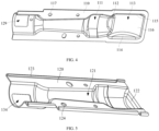
FIG. 4 is a schematic structural diagram of a first connecting plate in a gas-fired heating device according to an embodiment of the present application. -
FIG. 5 is a schematic structural diagram of a second connecting plate in a gas-fired heating device according to an embodiment of the present application. -
FIG. 6 is a second schematic structural diagram of a gas-fired heating device according to an embodiment of the present application. -
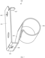
FIG. 7 is a schematic structural diagram of a fixing bracket in a gas-fired heating device according to an embodiment of the present application. -
FIG. 8 is a schematic structural diagram of a mounting bracket in a gas-fired heating device according to an embodiment of the present application. -
FIG. 9 is a schematic structural diagram of a burner in a gas-fired heating device according to an embodiment of the present application. -
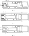
FIG. 10 is a first schematic structural diagram of a burner suitable for liquefied gas in a gas-fired heating device according to an embodiment of the present application. -
FIG. 11 is a second schematic structural diagram of a burner suitable for liquefied gas in a gas-fired heating device according to an embodiment of the present application. -
FIG. 12 is a schematic structural diagram of a burner suitable for natural gas in a gas-fired heating device according to an embodiment of the present application. - In the accompanying drawings:
100: burner 200: igniter 300: mounting bracket 400: fixing bracket 500: air inlet barrel 600: gas valve 700: inlet tube 701: inlet valve 800: combustion cylinder 101: nozzle 102: inlet port 110: first connecting plate 111: first groove 112: first flow guide groove wall 113: gas collecting chamber 114: first side wall 115: second side wall 116: flow guide wall 117: first connecting hole 120: second connecting plate 121: second groove 122: second flow guide groove wall 123: bent plate 124: second connecting hole 125: combustion-supporting air conditioner 126: rotatable tube 127: inlet plate 128: inlet hole 129: first adjusting opening 130: first limit hole 131: second limit hole 132: second adjusting opening 133: third limit hole 134: third adjusting opening 201: ignition end 202: fixing end 301: mounting plate 302: insertion block 401: first fixing plate 402: third connecting hole 403: second fixing plate 404: fixing hole 405: third fixing plate 406: fixing ring 407: fastening plate 501: air inlet clearance 502: fourth fixing plate 503: first plate body 504: second plate body 505: third plate body - First of all, persons of ordinary skill in the art should understand that these embodiments are only used for explanation of the technical principle of embodiments of the present application, and are not intended to limit the protection scope of embodiments of the present application. Persons of ordinary skill may make adjustment as needed so as to adapt to specific application scenarios.
- Secondly, it should be noted that in the description of embodiments of the present application, the terms for the direction or positional relationship indicated by the terms "inside" and "outside" and so on are based on the direction or positional relationship shown in the accompanying drawings, which is only for the convenience of description and not intended to indicate or imply that the device or component must be of a particular orientation, and be constructed and operate in a particular orientation, and therefore should not be understood as a limitation to embodiments of the present application.
- In addition, it should also be noted that, in the description of embodiments of the present application, unless otherwise expressly specified and limited, the terms "connected/connecting" and "connection" should be understood in a broad sense. For example, "connection" may be a fixed connection, a detachable connection, or an integral connection; "connection" may be a mechanical connection or an electrical connection; "connection" may be a direct connection or an indirect connection through an intermediate medium; and "connection" may be the internal communication of two components. For persons of ordinary skill in the art, the specific meanings of the above terms in embodiments of the present application may be understood according to specific situations.
- To make the objectives, technical solutions, and advantages of embodiments of the present application clearer, the technical solutions in embodiments of the present application will be described clearly and comprehensively below with reference to the accompanying drawings for embodiments of the present application. Apparently, the described embodiments are merely a part of embodiments rather than all embodiments of the present application. All other embodiments obtained by persons of ordinary skill in the art based on embodiments of the present application without creative effort shall fall within the protection scope of the present application.
- A gas-fired clothes dryer in the related art includes a housing, a clothes drying drum, a blower fan and a gas-fired heating device. The housing is internally provided with an accommodating space, and the clothes drying drum, the blower fan and the gas-fired heating device are all disposed in the accommodating space. The gas-fired heating device includes a gas valve, an inlet tube, a burner, a combustion cylinder and an igniter. The gas valve is provided with an inlet port and an outlet port, the inlet port is connected with the inlet tube, and the outlet port is connected with the burner. The burner is provided with a combustion-supporting air inlet port and a spray head, the combustion-supporting air inlet port is used for enabling the combustion-supporting air to enter the inside of the burner, and the combustion-supporting air is mixed with the gas in the burner and then the mixed gas is ejected out from the spray head. The igniter is disposed close to the burner. The spray head and the igniter are both accommodated in the combustion cylinder. The gas ejected from the spray head is ignited by the igniter, the heat generated by gas combustion heats the air in the combustion cylinder, and the heated air enters the clothes drying drum under the action of the blower fan to dry the clothes in the clothes drying drum.
- The spray head of the burner is generally hemispherical, and an axis of the hemispherical spray head is parallel to a horizontal plane. A plurality of nozzles are provided on the surface of the hemispherical spray head, and each of the nozzles faces a different direction. The gas is ejected from the nozzles. The gas ejected from the nozzles close to the igniter is easy to be ignited, while the gas ejected from the nozzles away from the igniter is difficult to be ignited by the igniter due to the long distance from the igniter and is easy to directly escape into the combustion cylinder without combustion, so that the gas ejected from the nozzles is not fully combusted, resulting in a decrease in the combustion efficiency of the gas and a waste of gas energy.
- Embodiments of the present application provide a gas-fired heating device and a gas-fired clothes dryer, where a gas collecting chamber is disposed outside a nozzle of a burner, and an ignition end of an igniter extends into the gas collecting chamber to ignite the gas in the gas collecting chamber. The gas ejected from the nozzle is gathered in the gas collecting chamber, and the gas collecting chamber can prevent the gas ejected from the nozzle from escaping to reduce the escaping amount of the gas, so that the gas ejected from the nozzle can be more fully combusted, thereby improving the combustion efficiency of the gas.
- The principles and features of embodiments of the present application are described below with reference to the accompanying drawings, and the examples given are merely used for explaining embodiments of the present application, and are not used for limiting the scope of embodiments of the present application.
- A gas-fired clothes dryer provided by an embodiment of the present application includes a housing, and a gas-fired heating device, a mounting
bracket 300, a clothes drying drum and a blower fan which are disposed in the housing. The clothes drying drum is used for placement of clothes to be dried. The gas-fired heating device is detachably connected to the mountingbracket 300, and the mountingbracket 300 is connected to the housing. - As shown in
FIG. 1 , the gas-fired heating device includes agas valve 600, aninlet tube 700, aburner 100, acombustion cylinder 800 and anigniter 200. Thegas valve 600 has an inlet port and an outlet port, the inlet port is connected with theinlet tube 700, and the outlet port is connected with theburner 100. Theinlet tube 700 may be provided with aninlet valve 701, and theinlet valve 701 is used for controlling the flow of the gas entering thegas valve 600 from theinlet tube 700. When theinlet valve 701 is opened, the gas in theinlet tube 700 may enter thegas valve 600; when theinlet valve 701 is closed, no gas flows through thegas valve 600. - As shown in
FIG. 2 , theburner 100 includes a body and a gas collecting plate. The body has an inlet end and a combustion end. The inlet end is provided with aninlet port 102, and theinlet port 102 is connected with an outlet port of thegas valve 600. The combustion end is provided with anozzle 101. The gas from thegas valve 600 enters the body from theinlet port 102 and is ejected out from thenozzle 101. - The gas collecting plate is concave upwards to form a
gas collecting chamber 113. The gas collecting plate is connected with the combustion end, and the gas collecting plate is located above thenozzle 101, so that the gas ejected from thenozzle 101 may enter thegas collecting chamber 113, and thegas collecting chamber 113 can prevent the gas ejected from thenozzle 101 from escaping, so as to reduce the escaping amount of the gas. - With continued reference to
FIG. 1 , anigniter 200 is disposed close to theburner 100. As shown inFIG. 3 , theigniter 200 has anignition end 201, theignition end 201 is located outside thenozzle 101, and theignition end 201 extends into thegas collecting chamber 113, so that theigniter 200 may ignite the gas in thegas collecting chamber 113. Theignition end 201 extends into thegas collecting chamber 113, which allows theigniter 200 to ignite faster. - With continued reference to
FIG. 1 , thecombustion cylinder 800 is sleeved outside thenozzle 101, thegas collecting chamber 113 and theigniter 200, and thecombustion cylinder 800 can be connected with the clothes drying drum through an air channel. The heat generated by gas combustion in thegas collecting chamber 113 heats the air in thecombustion cylinder 800, and the heated air enters the clothes drying drum under the action of the blower fan to dry the clothes in the clothes drying drum. - The gas in the
burner 100 is ejected from thenozzle 101 and gathered in thegas collecting chamber 113, and theignition end 201 of theigniter 200 extends into thegas collecting chamber 113, so that the gas is mainly combusted in thegas collecting chamber 113. The length of the generated flame in the direction parallel to the gas channel is short, and the flame is away from the inlet port of the air channel, thereby preventing the temperature of the air entering the clothes drying drum from becoming over high and damaging the clothes. - The body may include a first connecting
plate 110 and a second connectingplate 120, and the first connectingplate 110 is attached to the second connectingplate 120. As shown inFIG. 4 , the first connectingplate 110 is provided with afirst groove 111, and thefirst groove 111 is concave away from the second connectingplate 120. As shown inFIG. 5 , the second connectingplate 120 is provided with asecond groove 121, and thesecond groove 121 is concave away from the first connectingplate 110. With continued reference toFIG. 2 , thesecond groove 121 is right opposite to thefirst groove 111, and the gas channel is formed by being enclosed by thesecond groove 121 and thefirst groove 111. Anozzle 101 is formed at the end of the gas channel close to thegas collecting chamber 113, andinlet port 102 is formed at the end of the gas channel away from thegas collecting chamber 113. The gas channel is connected with thegas collecting chamber 113 through thenozzle 101. The gas ejected from thenozzle 101 firstly flows into thegas collecting chamber 113, and thegas collecting chamber 113 can reduce the escaping amount of the gas, so that the gas ejected from thenozzle 101 may be ignited by theigniter 200 as much as possible, thereby improving the combustion efficiency of the gas. - The first connecting
plate 110 may be flush with the gas collecting plate, and the first connectingplate 110 and the gas collecting plate may be integrally formed. Thefirst groove 111 and thegas collecting chamber 113 are located on the same side of the second connectingplate 120 to make the structure of theburner 100 simpler. - In addition to the above structure of the
burner 100, theburner 100 may also be formed by welding a gas collecting cover on the basis of theburner 100 in the related art. That is, one end of theburner 100 away from theinlet port 102 is a hemispherical spray head, and an axis of the hemispherical spray head may be parallel to a horizontal plane. A plurality ofnozzles 101 are provided on the surface of the hemispherical spray head, and each of thenozzles 101 faces a different direction. Gas is ejected from thenozzles 101. Agas collecting chamber 113 is provided under the gas collecting cover, and theignition end 201 of theigniter 200 extends into thegas collecting chamber 113. The gas collecting cover in this embodiment can block the escape path of the gas to prevent the gas from escaping to the side of the gas collecting cover away from theigniter 200, so that the gas ejected from thenozzle 101 can be gathered in thegas collecting chamber 113 as much as possible and ignited by theigniter 200, thereby improving the combustion efficiency of the gas. - With continued reference to
FIG. 2 andFIG. 4 , in the implementation that the first connectingplate 110 is provided with thefirst groove 111 and thegas collecting chamber 113, thefirst groove 111 has a first flowguide groove wall 112, and the first flowguide groove wall 112 is close to thegas collecting chamber 113. The first flowguide groove wall 112 is disposed inclined relative to the first connectingplate 110, and a distance between the first flowguide groove wall 112 and theinlet port 102 increases from the groove bottom of thefirst groove 111 to the groove opening of thefirst groove 111. The gas in thefirst groove 111 may flow to thenozzle 101 along the first flowguide groove wall 112 and then flow into thegas collecting chamber 113, and the first flowguide groove wall 112 makes the gas in thefirst groove 111 easily flow into thegas collecting chamber 113. - With continued reference to
FIG. 2 andFIG. 5 , in the implementation that the second connectingplate 120 is provided with thesecond groove 121, thesecond groove 121 has a second flow guidegroove wall 122, and the second flow guidegroove wall 122 is close to thegas collecting chamber 113. Thenozzle 101 is formed by being enclosed by one end of the second flow guidegroove wall 122 away from the groove bottom of thesecond groove 121 and one end of the first flowguide groove wall 112 away from the groove bottom of thefirst groove 111. The second flow guidegroove wall 122 is disposed inclined relative to the second connectingplate 120, and a distance between the second flow guidegroove wall 122 and theinlet port 102 increases from the groove bottom of thesecond groove 121 to the groove opening of thesecond groove 121. The gas in thesecond groove 121 may flow into thegas collecting chamber 113 along the second flow guidegroove wall 122, and the second flow guidegroove wall 122 makes the gas in thesecond groove 121 easily flow into thegas collecting chamber 113. - With continued reference to
FIG. 2 , a projection of one end of the first flowguide groove wall 112 away from the groove bottom of thefirst groove 111 on a plane where the first connectingplate 110 is located lies within a projection of the second flow guidegroove wall 122 on the plane where the first connectingplate 110 is located. Part of the gas flowing through the first flowguide groove wall 112 flows into thegas collecting chamber 113 from thenozzle 101, and the other part directly flows to the second flow guidegroove wall 122, and flows to thenozzle 101 along the second flow guidegroove wall 122 and then to thegas collecting chamber 113. The second flow guidegroove wall 122 can block the gas from the first flowguide groove wall 112, so as to prevent the gas from escaping to the outside of thegas collecting chamber 113, thereby further improving the combustion efficiency of the gas. - With continued reference to
FIG. 5 , thegas collecting chamber 113 may include afirst side wall 114, asecond side wall 115 and aflow guide wall 116. Thefirst side wall 114 is perpendicular to the first connectingplate 110, and thefirst side wall 114 is parallel to the axis of the gas channel. Thesecond side wall 115 and thefirst side wall 114 are parallel and spaced apart from each other, thefirst side wall 114 and thesecond side wall 115 are connected by theflow guide wall 116, and thegas collecting chamber 113 is formed by being enclosed by thefirst side wall 114, thesecond side wall 115 and theflow guide wall 116. One end of theflow guide wall 116 close to thenozzle 101 is connected with one end of the first flowguide groove wall 112 close to the second connectingplate 120, and the gas ejected from thenozzle 101 flows into thegas collecting chamber 113 along theflow guide wall 116. - With continued reference to
FIG. 2 , a projection of theflow guide wall 116 on a plane where thefirst side wall 114 is located is in a circular arc shape. That is, theflow guide wall 116 is in the shape of a curved surface. The gas flowing from one end of theflow guide wall 116 close to thenozzle 101 to the other end of theflow guide wall 116 turns back after contacting theflow guide wall 116 at the other end and forms turbulent flow in thegas collecting chamber 113. Therefore, the gas in thegas collecting chamber 113 can contact theigniter 200 as much as possible and be ignited by theigniter 200 to improve the combustion efficiency of the gas, and at the same time, the gas may be combusted more fully, thereby reducing the residue of carbon monoxide, making the safety higher and being more energy-saving and environment-friendly. - With continued reference to
FIG. 3 , in some embodiments, the angle between the axis of theigniter 200 and the plane where the first connectingplate 110 is located is an acute angle. Theigniter 200 further has a fixingend 202 which is closer to theinlet port 102 than theignition end 201. Theigniter 200 is disposed inclined outside thenozzle 101, so that theignition end 201 is right opposite to thenozzle 101, and the gas may be ignited immediately after being ejected from thenozzle 101, which can effectively reduce the ignition time of the gas-fired clothes dryer. Therefore, the heat generated by gas combustion is exchanged with wet clothes more quickly, thereby effectively improving the drying speed of the clothes. - Further, an angle between the axis of the
igniter 200 and the plane where the first connectingplate 110 is located may be 18° to 30°, so that the contact area between the gas ejected from thenozzle 101 and theignition end 201 may be increased, and the gas may be ignited by theigniter 200 as much as possible to increase the combustion efficiency of the gas. - In the implementation that the
burner 100 includes the first connectingplate 110 and the second connectingplate 120, the second connectingplate 120 is bent upwards along two ends of the axis perpendicular to the gas channel to form bent plates 123 (as shown inFIG. 5 ). Slots are formed by being enclosed by thebent plates 123 and the second connectingplate 120, and the first connectingplate 110 is embedded into the slots (as shown inFIG. 6 ), so that thefirst connection plate 110 is connected with thesecond connection plate 120. - The first connecting
plate 110 may be provided with a first connecting hole 117 (as shown inFIG. 4 ), and the second connectingplate 120 may be provided with a second connecting hole 124 (as shown inFIG. 5 ). The first connectinghole 117 is right opposite to the second connectinghole 124. A fastening bolt passes through the first connectinghole 117 and the second connectinghole 124 in sequence and then is connected with the mounting bracket 300 (as shown inFIG. 6 ), so that theburner 100 is detachably connected to the mountingbracket 300. - With continued reference to
FIG. 1 , theigniter 200 may be connected to the mountingbracket 300 through a fixingbracket 400. Specifically, as shown inFIG. 7 , the fixingbracket 400 includes afirst fixing plate 401, asecond fixing plate 403 and a clamping part. One end of thesecond fixing plate 403 is connected with thefirst fixing plate 401, and thesecond fixing plate 403 is perpendicular to thefirst fixing plate 401. The other end of thesecond fixing plate 403 is connected with the clamping part. One end of thefirst fixing plate 401 away from thesecond fixing plate 403 is bent toward the clamping part to form afastening plate 407, and thefastening plate 407 is perpendicular to thefirst fixing plate 401. Thefastening plate 407, thefirst fixing plate 401, and thesecond fixing plate 403 form a clamping slot. A fixinghole 404 is provided on thesecond fixing plate 403, and the fixinghole 404 extends to thefirst fixing plate 401. As shown inFIG. 8 , the mountingbracket 300 is provided with a mountingplate 301, and the edge of the mountingplate 301 is provided with aninsertion block 302. After theinsertion block 302 is embedded into the fixinghole 404, the fixingbracket 400 is rotated so that the mountingplate 301 is clamped in the clamping slot (as shown inFIG. 3 andFIG. 6 ), and thefirst fixing plate 401 is attached to the mountingplate 301, so as to pre-position the fixingbracket 400 and the mountingbracket 300. Thefirst fixing plate 401 may be provided with a third connectinghole 402, the mountingplate 301 may be provided with a fourth connecting hole, and the fourth connecting hole is right opposite to the third connectinghole 402. A fastening bolt is threaded into the third connectinghole 402 and the fourth connecting hole (as shown inFIG. 6 ) to fix the mountingplate 301 and thefirst fixing plate 401. - With continued reference to
FIG. 7 , in some embodiments, the clamping part may include athird fixing plate 405. One end of thethird fixing plate 405 is connected with one end of thesecond fixing plate 403 away from thefirst fixing plate 401, and the other end of thethird fixing plate 405 is bent to form a fixingring 406. The fixingend 202 of theigniter 200 is threaded into the fixingring 406, so as to fixedly connect theigniter 200 to the fixingbracket 400. - In other embodiments, the clamping part may include a fixing clip, which may clamp the
ignition end 201 of theigniter 200, so as to fix theigniter 200 to the fixingbracket 400. - With continued reference to
FIG. 1 , in some embodiments, the gas-fired heating device may further include anair inlet barrel 500. One end of thecombustion cylinder 800 is sleeved outside theigniter 200 and thegas collecting chamber 113, the other end of thecombustion cylinder 800 extends away from theburner 100, and the diameter of thecombustion cylinder 800 decreases in the direction away from theburner 100. Theair inlet barrel 500 is sleeved outside one end of thecombustion cylinder 800 away from theburner 100, and one end of thecombustion cylinder 800 away from theburner 100 is accommodated in theair inlet barrel 500. The axis of theair inlet barrel 500 and the axis of thecombustion cylinder 800 may be collinear. The barrel diameter of theair inlet barrel 500 is reduced along the direction away from theburner 100. There is anair inlet clearance 501 between theair inlet barrel 500 and thecombustion cylinder 800. The air in the housing enters theair inlet barrel 500 from theair inlet clearance 501, mixes with the hot air in thecombustion cylinder 800 and then enters the air channel and flows from the air channel into the clothes drying drum. - In a case of high power conditions, high loads or poor air paths due to thread debris blockage, the temperature of the air in the
combustion cylinder 800 may be too high. The air entering theair inlet barrel 500 from theair inlet clearance 501 is mixed with the air from thecombustion cylinder 800 and then enters the clothes drying drum, so as to reduce the temperature of the air entering the clothes drying drum and avoid damage to the clothes when the temperature is too high. - With continued reference to
FIG. 1 , theair inlet barrel 500 and thecombustion cylinder 800 may be connected by afourth fixing plate 502. Thefourth fixing plate 502 may include afirst plate body 503, asecond plate body 504 and athird plate body 505. Thefirst plate body 503 is attached to the outer wall of thecombustion cylinder 800. One end of thesecond plate body 504 is connected with one end of thefirst plate body 503, and the other end of thesecond plate body 504 is connected with theair inlet barrel 500. One end of thethird plate body 505 is connected with one end of thefirst plate body 503 away from thesecond plate body 504, and the other end of thethird plate body 505 is connected to theair inlet barrel 500. In the direction from thefirst plate body 503 towards theair inlet barrel 500, a distance between thesecond plate body 504 and thethird plate body 505 gradually increases. A fastening bolt is connected with thecombustion cylinder 800 after passing through thefirst plate body 503, so as to realize the connection between theair inlet barrel 500 and thecombustion cylinder 800. - As shown in
FIG. 9 , in the implementation that the body includes the first connectingplate 110 and the second connectingplate 120, theburner 100 may further include a combustion-supportingair conditioner 125. The combustion-supportingair conditioner 125 includes arotatable tube 126 and aninlet plate 127. Therotatable tube 126 inserted within one end of the gas channel away from thegas collecting chamber 113. Therotatable tube 126 may rotate in the gas channel by taking the axis of therotatable tube 126 as the center. Theinlet plate 127 is disposed at one end of therotatable tube 126 away from thegas collecting chamber 113 to block therotatable tube 126, and theinlet plate 127 is perpendicular to the axis of therotatable tube 126. Theinlet plate 127 may be provided with aninlet hole 128. The gas from thegas valve 600 enters therotatable tube 126 from theinlet hole 128, and flows from therotatable tube 126 into the gas channel. The wall of thefirst groove 111 may be provided with afirst adjusting opening 129, afirst limit hole 130 and asecond limit hole 131. The wall of therotatable tube 126 may be provided with a second adjusting opening 132 and athird limit hole 133. The axes of thethird limit hole 133, thefirst limit hole 130 and thesecond limit hole 131 are located in the same plane perpendicular to the axis of therotatable tube 126. Thethird limit hole 133 is used to be in alignment with thefirst limit hole 130 or thesecond limit hole 131, and thethird limit hole 133 may be connected with thefirst limit hole 130 or thesecond limit hole 131 by a fastening bolt. The flow area of thefirst adjusting opening 129 and the second adjusting opening 132 when thethird limit hole 133 is in alignment with thefirst limit hole 130 is larger than the flow area of thefirst adjusting opening 129 and the second adjusting opening 132 when thethird limit hole 133 is in alignment with thesecond limit hole 131. - With continued reference to
FIG. 5 , the wall of thesecond groove 121 may be provided with a third adjusting opening 134, and the third adjusting opening 134 may be right opposite to thefirst adjusting opening 129. The wall of therotatable tube 126 may be provided with a fourth adjusting opening, and the fourth adjusting opening may be right opposite to thesecond adjusting opening 132. The flow area of the third adjusting opening 134 and the fourth adjusting opening is equal to the flow area of thefirst adjusting opening 129 and thesecond adjusting opening 132. The flow area of the third adjusting opening 134 and the fourth adjusting opening when thethird limit hole 133 is in alignment with thefirst limit hole 130 is greater than the flow area of the third adjusting opening 134 and the fourth adjusting opening when thethird limit hole 133 is in alignment with thesecond limit hole 131. - The gas used by the gas-fired clothes dryer may be natural gas or liquefied gas. The amount of combustion-supporting air required by the natural gas and the liquefied gas during combustion is greatly different. For combusting the same volume of natural gas and liquefied gas, the amount of combustion-supporting air required by the liquefied gas is greater than that required by the natural gas.
- As shown in
FIG. 10 and FIG. 11 , when the gas used in the gas-fired clothes dryer is liquefied gas, therotatable tube 126 is rotated until thefirst limit hole 130 is in alignment with thethird limit hole 133, and the fastening bolt is threaded into thefirst limit hole 130 and thethird limit hole 133. At this time, the tube wall of therotatable tube 126 does not block thefirst adjusting opening 129 and thethird adjusting opening 134. That is, the second adjusting opening 132 is completely opposite to thefirst adjusting opening 129, and the third adjusting opening 134 is completely opposite to the fourth adjusting opening. At this time, the flow area between the first adjusting opening 129 or the third adjusting opening 134 and the gas channel is a first area. - As shown in
FIG. 12 , when the gas used in the gas-fired clothes dryer is natural gas, therotatable tube 126 is rotated until thesecond limit hole 131 is in alignment with thethird limit hole 133, and the fastening bolt is threaded into thesecond limit hole 131 and thethird limit hole 133. At this time, the tube wall of therotatable tube 126 blocks part of thefirst adjusting opening 129 and thethird adjusting opening 134. That is, part of the second adjusting opening 132 is right opposite to part of thefirst adjusting opening 129, and part of the third adjusting opening 134 is right opposite to part of the fourth adjusting opening. At this time, the flow area between the first adjusting opening 129 or the third adjusting opening 134 and the gas channel is a second area, and the second area is smaller than the first area, so as to accommodate the amount of combustion-supporting air required for combustion of natural gas. - When the gas used by the gas-fired clothes dryer needs to be changed, the flow area between the
first adjusting opening 129 and the third adjusting opening 134 and the gas channel can be changed by simply rotating the combustion-supportingair conditioner 125 without replacing the gas valve. - Further, the first area may be three times the second area. Since the amount of combustion-supporting air required by the liquefied gas is about three times the amount of combustion-supporting air required by the natural gas when the same volume of natural gas and liquefied gas is combusted, by setting the first area to be three times the second area, the gas-fired clothes dryer can achieve a reasonable ratio of gas to combustion-supporting air under either natural gas or liquefied gas operating conditions.
- To sum up, the gas-fired clothes dryer according to embodiments of the present application includes the gas-fired heating device, and the gas-fired heating device include a
burner 100 and anigniter 200. The burner includes a body and a gas collecting plate, the gas collecting plate is concave upwards to form agas collecting chamber 113. The body has a combustion end provided with anozzle 101. The gas collecting plate is connected with the combustion end, and the gas collecting plate is located above thenozzle 101, so that gas ejected from thenozzle 101 enters thegas collecting chamber 113. Theigniter 200 is provided with anignition end 201 located outside thenozzle 101, and theignition end 201 extends into thegas collecting chamber 113. By the above arrangement, the gas ejected from thenozzle 101 is firstly gathered in thegas collecting chamber 113, and thegas collecting chamber 113 can prevent the gas ejected from thenozzle 101 from escaping to reduce the escaping amount of the gas, so that the gas ejected from thenozzle 101 can be ignited by theigniter 200 as much as possible, thereby improving the combustion efficiency of the gas. - Finally, it should be noted that the foregoing embodiments are merely intended for describing the technical solutions of the present application rather than limiting the present application; although the present application is described in detail with reference to the foregoing embodiments, persons of ordinary skill in the art should understand that modification may be made to the technical solutions described in the foregoing embodiments or equivalent substitutions may be made to some or all technical features thereof; and these modifications and substitutions shall not cause the essence of the corresponding technical solutions to depart from the scope of the technical solutions of embodiments of the present application.
Claims (10)
- A gas-fired heating device, comprising a burner and an igniter, wherein the burner comprises a body and a gas collecting plate, the gas collecting plate is concave upwards to form a gas collecting chamber, and the body has a combustion end provided with a nozzle; the gas collecting plate is connected with the combustion end, and the gas collecting plate is located above the nozzle, so that gas ejected from the nozzle enters the gas collecting chamber; the igniter is provided with an ignition end located outside the nozzle, and the ignition end extends into the gas collecting chamber.
- The gas-fired heating device according to claim 1, wherein the body comprises a first connecting plate and a second connecting plate, the first connecting plate is attached to the second connecting plate, the first connecting plate is provided with a first groove, and the first groove is concave away from the second connecting plate;
the second connecting plate is provided with a second groove, the second groove is concave away from the first connecting plate, the second groove is right opposite to the first groove, and a gas channel is formed by being enclosed by the second groove and the first groove; the nozzle is formed at one end of the gas channel close to the gas collecting chamber, an inlet port is formed at one end of the gas channel away from the gas collecting chamber, and the gas channel is connected with the gas collecting chamber through the nozzle. - The gas-fired heating device according to claim 2, wherein the first groove is provided with a first flow guide groove wall, the first flow guide groove wall is close to the gas collecting chamber, the first flow guide groove wall is disposed inclined relative to the first connecting plate, and a distance between the first flow guide groove wall and the inlet port increases from a groove bottom of the first groove to a groove opening of the first groove.
- The gas-fired heating device according to claim 2 or 3, wherein the second groove is provided with a second flow guide groove wall, the second flow guide groove wall is close to the gas collecting chamber, the second flow guide groove wall is disposed inclined relative to the second connecting plate, and a distance between the second flow guide groove wall and the inlet port increases from a groove bottom of the second groove to a groove opening of the second groove.
- The gas-fired heating device according to claim 3, wherein the gas collecting chamber comprises a first side wall, a second side wall and a flow guide wall, the first side wall is perpendicular to the first connecting plate, and the first side wall is parallel to an axis of the gas channel; the second side wall and the first side wall are parallel and spaced apart from each other, and the first side wall and the second side wall are connected through the flow guide wall; the gas collecting chamber is formed by being enclosed by the first side wall, the second side wall and the flow guide wall, and one end of the flow guide wall close to the nozzle is connected with one end of the first flow guide groove wall close to the second connecting plate.
- The gas-fired heating device according to claim 5, wherein a projection of the flow guide wall on a plane where the first side wall is located is in a circular arc shape.
- The gas-fired heating device according to any one of claims 2 to 6, wherein an angle between an axis of the igniter and a plane where the first connecting plate is located is an acute angle; the igniter further has a fixing end, and the fixing end is closer to the inlet port than the ignition end.
- The gas-fired heating device according to any one of claims 2 to 7, wherein the second connecting plate is bent upward along two ends of an axis perpendicular to the gas channel to form bent plates, slots are formed by being enclosed by the bent plates and the second connecting plate, and the first connecting plate is embedded into the slots.
- The gas-fired heating device according to any one of claims 1 to 8, wherein the gas-fired heating device further comprises a mounting bracket, and the burner and the igniter are both connected to the mounting bracket.
- A gas-fired clothes dryer, comprising the gas-fired heating device according to any one of claims 1 to 9.
Applications Claiming Priority (2)
| Application Number | Priority Date | Filing Date | Title |
|---|---|---|---|
| CN202210181871.2A CN114561787A (en) | 2022-02-25 | 2022-02-25 | Gas heating device and gas clothes dryer |
| PCT/CN2023/074145 WO2023160345A1 (en) | 2022-02-25 | 2023-02-01 | Gas heating apparatus and gas clothes dryer |
Publications (1)
| Publication Number | Publication Date |
|---|---|
| EP4484637A1 true EP4484637A1 (en) | 2025-01-01 |
Family
ID=81715804
Family Applications (1)
| Application Number | Title | Priority Date | Filing Date |
|---|---|---|---|
| EP23758970.0A Withdrawn EP4484637A1 (en) | 2022-02-25 | 2023-02-01 | Gas heating apparatus and gas clothes dryer |
Country Status (4)
| Country | Link |
|---|---|
| US (1) | US20240410570A1 (en) |
| EP (1) | EP4484637A1 (en) |
| CN (1) | CN114561787A (en) |
| WO (1) | WO2023160345A1 (en) |
Families Citing this family (3)
| Publication number | Priority date | Publication date | Assignee | Title |
|---|---|---|---|---|
| CN114561787A (en) * | 2022-02-25 | 2022-05-31 | 青岛海尔洗涤电器有限公司 | Gas heating device and gas clothes dryer |
| CN117286698B (en) * | 2022-06-16 | 2026-03-06 | 青岛胶州海尔洗涤电器有限公司 | Gas-fired heating devices and garment care machines with them |
| CN121854898B (en) * | 2026-03-18 | 2026-05-19 | 中国航发湖南动力机械研究所 | A combustion chamber head structure and combustion chamber |
Family Cites Families (12)
| Publication number | Priority date | Publication date | Assignee | Title |
|---|---|---|---|---|
| GB1235139A (en) * | 1968-11-08 | 1971-06-09 | William Bailey Birmingham Ltd | Improvements in or relating to gas burners and burner heads therefor |
| DE60220523T2 (en) * | 2001-07-19 | 2008-02-07 | Lg Electronics Inc. | GAS BURNER FOR DRYERS |
| KR100937409B1 (en) * | 2002-12-05 | 2010-01-18 | 엘지전자 주식회사 | Gas Combustion Device for Dryer |
| US20110179666A1 (en) * | 2010-01-27 | 2011-07-28 | Castfutura S.P.A. | Burner for dryers and process of manufacturing said burner |
| CN102213419B (en) * | 2010-04-12 | 2014-07-02 | 毛羽 | Novel side wall gas burner |
| CN206669739U (en) * | 2017-04-05 | 2017-11-24 | 曾觐伦 | A kind of high-effect burner of single head |
| CN109930372B (en) * | 2017-12-15 | 2023-07-04 | 青岛海尔洗衣机有限公司 | Ignition structure of gas clothes dryer and gas clothes dryer |
| CN110864286A (en) * | 2018-08-28 | 2020-03-06 | 无锡小天鹅电器有限公司 | Nozzle for burner and burner and clothes dryer having the same |
| CN111336517A (en) * | 2018-12-18 | 2020-06-26 | 无锡小天鹅电器有限公司 | Nozzle assembly of burner, burner and clothes dryer |
| CN111578323B (en) * | 2020-06-23 | 2025-05-30 | 杭州老板电器股份有限公司 | Gas range |
| CN112856492B (en) * | 2021-01-15 | 2022-04-05 | 宁波方太厨具有限公司 | Combustor and gas stove comprising same |
| CN114561787A (en) * | 2022-02-25 | 2022-05-31 | 青岛海尔洗涤电器有限公司 | Gas heating device and gas clothes dryer |
-
2022
- 2022-02-25 CN CN202210181871.2A patent/CN114561787A/en active Pending
-
2023
- 2023-02-01 EP EP23758970.0A patent/EP4484637A1/en not_active Withdrawn
- 2023-02-01 WO PCT/CN2023/074145 patent/WO2023160345A1/en not_active Ceased
-
2024
- 2024-08-19 US US18/809,271 patent/US20240410570A1/en active Pending
Also Published As
| Publication number | Publication date |
|---|---|
| US20240410570A1 (en) | 2024-12-12 |
| WO2023160345A1 (en) | 2023-08-31 |
| CN114561787A (en) | 2022-05-31 |
Similar Documents
| Publication | Publication Date | Title |
|---|---|---|
| US20240410570A1 (en) | Gas-fired heating device and gas-fired clothes dryer | |
| CN112682781B (en) | Combustor and gas water heater | |
| US20230203746A1 (en) | Burner and gas fired clothes dryer | |
| US7172413B2 (en) | Laundry dryer having gas combustion apparatus | |
| US20240410106A1 (en) | Gas-fired clothes dryer | |
| CN108006962B (en) | A gas heater | |
| CN116697600A (en) | A gas water heater with a down-blown air-cooled single-row heat exchanger | |
| CN217266530U (en) | Combustion cylinder and clothes processor | |
| KR100819492B1 (en) | High efficiency direct type dryer | |
| CN217004445U (en) | Direct-fired heating furnace with flow equalizing plate | |
| KR100780348B1 (en) | Hot air supply device for dryer | |
| CN116951404A (en) | Premixing device, combustion device and gas water heating equipment | |
| JP3075329U (en) | Gas oven combustion equipment | |
| CN112944674A (en) | High-efficient gas heating boiler | |
| CN216205282U (en) | Heat preservation device for special-shaped burner block of heat storage furnace mouth | |
| CN223649304U (en) | Infrared burner | |
| KR100869504B1 (en) | Gas Combustion Device for Dryer | |
| KR100798942B1 (en) | Gas Combustion Device for Dryer | |
| CN222895324U (en) | A high-efficiency heating device for a heater | |
| US3606608A (en) | Encasement and fuel burner assembly | |
| KR100851531B1 (en) | Hot Heater | |
| CN207316979U (en) | A kind of high-power full premixed condensed water heater combustion system | |
| WO2023072278A1 (en) | Burner, combustion heating system, and laundry treating apparatus | |
| KR100869503B1 (en) | Gas Combustion Device for Dryer | |
| KR0132199Y1 (en) | Combustion device of hot air heater |
Legal Events
| Date | Code | Title | Description |
|---|---|---|---|
| STAA | Information on the status of an ep patent application or granted ep patent |
Free format text: STATUS: THE INTERNATIONAL PUBLICATION HAS BEEN MADE |
|
| PUAI | Public reference made under article 153(3) epc to a published international application that has entered the european phase |
Free format text: ORIGINAL CODE: 0009012 |
|
| STAA | Information on the status of an ep patent application or granted ep patent |
Free format text: STATUS: REQUEST FOR EXAMINATION WAS MADE |
|
| STAA | Information on the status of an ep patent application or granted ep patent |
Free format text: STATUS: THE APPLICATION HAS BEEN WITHDRAWN |
|
| 17P | Request for examination filed |
Effective date: 20240816 |
|
| AK | Designated contracting states |
Kind code of ref document: A1 Designated state(s): AL AT BE BG CH CY CZ DE DK EE ES FI FR GB GR HR HU IE IS IT LI LT LU LV MC ME MK MT NL NO PL PT RO RS SE SI SK SM TR |
|
| 18W | Application withdrawn |
Effective date: 20241219 |