EP4484583A1 - A method of manufacturing blades of a cutting device - Google Patents
A method of manufacturing blades of a cutting device Download PDFInfo
- Publication number
- EP4484583A1 EP4484583A1 EP23181440.1A EP23181440A EP4484583A1 EP 4484583 A1 EP4484583 A1 EP 4484583A1 EP 23181440 A EP23181440 A EP 23181440A EP 4484583 A1 EP4484583 A1 EP 4484583A1
- Authority
- EP
- European Patent Office
- Prior art keywords
- blade
- hardness
- cutting
- edges
- cutting device
- Prior art date
- Legal status (The legal status is an assumption and is not a legal conclusion. Google has not performed a legal analysis and makes no representation as to the accuracy of the status listed.)
- Pending
Links
Images


Classifications
-
- A—HUMAN NECESSITIES
- A01—AGRICULTURE; FORESTRY; ANIMAL HUSBANDRY; HUNTING; TRAPPING; FISHING
- A01G—HORTICULTURE; CULTIVATION OF VEGETABLES, FLOWERS, RICE, FRUIT, VINES, HOPS OR SEAWEED; FORESTRY; WATERING
- A01G3/00—Cutting implements specially adapted for horticultural purposes; Delimbing standing trees
- A01G3/02—Secateurs; Flower or fruit shears
- A01G3/025—Secateurs; Flower or fruit shears having elongated or extended handles
- A01G3/0255—Tree pruners, i.e. pruning shears carried at the end of a pole
-
- B—PERFORMING OPERATIONS; TRANSPORTING
- B23—MACHINE TOOLS; METAL-WORKING NOT OTHERWISE PROVIDED FOR
- B23P—METAL-WORKING NOT OTHERWISE PROVIDED FOR; COMBINED OPERATIONS; UNIVERSAL MACHINE TOOLS
- B23P15/00—Making specific metal objects by operations not covered by a single other subclass or a group in this subclass
- B23P15/28—Making specific metal objects by operations not covered by a single other subclass or a group in this subclass cutting tools
-
- A—HUMAN NECESSITIES
- A01—AGRICULTURE; FORESTRY; ANIMAL HUSBANDRY; HUNTING; TRAPPING; FISHING
- A01G—HORTICULTURE; CULTIVATION OF VEGETABLES, FLOWERS, RICE, FRUIT, VINES, HOPS OR SEAWEED; FORESTRY; WATERING
- A01G3/00—Cutting implements specially adapted for horticultural purposes; Delimbing standing trees
- A01G3/04—Apparatus for trimming hedges, e.g. hedge shears
- A01G3/047—Apparatus for trimming hedges, e.g. hedge shears portable
-
- A—HUMAN NECESSITIES
- A01—AGRICULTURE; FORESTRY; ANIMAL HUSBANDRY; HUNTING; TRAPPING; FISHING
- A01G—HORTICULTURE; CULTIVATION OF VEGETABLES, FLOWERS, RICE, FRUIT, VINES, HOPS OR SEAWEED; FORESTRY; WATERING
- A01G3/00—Cutting implements specially adapted for horticultural purposes; Delimbing standing trees
- A01G3/04—Apparatus for trimming hedges, e.g. hedge shears
- A01G3/047—Apparatus for trimming hedges, e.g. hedge shears portable
- A01G3/053—Apparatus for trimming hedges, e.g. hedge shears portable motor-driven
-
- B—PERFORMING OPERATIONS; TRANSPORTING
- B23—MACHINE TOOLS; METAL-WORKING NOT OTHERWISE PROVIDED FOR
- B23K—SOLDERING OR UNSOLDERING; WELDING; CLADDING OR PLATING BY SOLDERING OR WELDING; CUTTING BY APPLYING HEAT LOCALLY, e.g. FLAME CUTTING; WORKING BY LASER BEAM
- B23K26/00—Working by laser beam, e.g. welding, cutting or boring
- B23K26/36—Removing material
- B23K26/38—Removing material by boring or cutting
-
- C—CHEMISTRY; METALLURGY
- C21—METALLURGY OF IRON
- C21D—MODIFYING THE PHYSICAL STRUCTURE OF FERROUS METALS; GENERAL DEVICES FOR HEAT TREATMENT OF FERROUS OR NON-FERROUS METALS OR ALLOYS; MAKING METAL MALLEABLE, e.g. BY DECARBURISATION OR TEMPERING
- C21D1/00—General methods or devices for heat treatment, e.g. annealing, hardening, quenching or tempering
- C21D1/06—Surface hardening
-
- C—CHEMISTRY; METALLURGY
- C21—METALLURGY OF IRON
- C21D—MODIFYING THE PHYSICAL STRUCTURE OF FERROUS METALS; GENERAL DEVICES FOR HEAT TREATMENT OF FERROUS OR NON-FERROUS METALS OR ALLOYS; MAKING METAL MALLEABLE, e.g. BY DECARBURISATION OR TEMPERING
- C21D1/00—General methods or devices for heat treatment, e.g. annealing, hardening, quenching or tempering
- C21D1/18—Hardening; Quenching with or without subsequent tempering
-
- C—CHEMISTRY; METALLURGY
- C21—METALLURGY OF IRON
- C21D—MODIFYING THE PHYSICAL STRUCTURE OF FERROUS METALS; GENERAL DEVICES FOR HEAT TREATMENT OF FERROUS OR NON-FERROUS METALS OR ALLOYS; MAKING METAL MALLEABLE, e.g. BY DECARBURISATION OR TEMPERING
- C21D1/00—General methods or devices for heat treatment, e.g. annealing, hardening, quenching or tempering
- C21D1/26—Methods of annealing
-
- C—CHEMISTRY; METALLURGY
- C21—METALLURGY OF IRON
- C21D—MODIFYING THE PHYSICAL STRUCTURE OF FERROUS METALS; GENERAL DEVICES FOR HEAT TREATMENT OF FERROUS OR NON-FERROUS METALS OR ALLOYS; MAKING METAL MALLEABLE, e.g. BY DECARBURISATION OR TEMPERING
- C21D6/00—Heat treatment of ferrous alloys
-
- C—CHEMISTRY; METALLURGY
- C21—METALLURGY OF IRON
- C21D—MODIFYING THE PHYSICAL STRUCTURE OF FERROUS METALS; GENERAL DEVICES FOR HEAT TREATMENT OF FERROUS OR NON-FERROUS METALS OR ALLOYS; MAKING METAL MALLEABLE, e.g. BY DECARBURISATION OR TEMPERING
- C21D8/00—Modifying the physical properties of ferrous metals or ferrous alloys by deformation combined with, or followed by, heat treatment
-
- C—CHEMISTRY; METALLURGY
- C21—METALLURGY OF IRON
- C21D—MODIFYING THE PHYSICAL STRUCTURE OF FERROUS METALS; GENERAL DEVICES FOR HEAT TREATMENT OF FERROUS OR NON-FERROUS METALS OR ALLOYS; MAKING METAL MALLEABLE, e.g. BY DECARBURISATION OR TEMPERING
- C21D9/00—Heat treatment, e.g. annealing, hardening, quenching or tempering, adapted for particular articles; Furnaces therefor
- C21D9/18—Heat treatment, e.g. annealing, hardening, quenching or tempering, adapted for particular articles; Furnaces therefor for knives, scythes, scissors, or like hand cutting tools
-
- C—CHEMISTRY; METALLURGY
- C21—METALLURGY OF IRON
- C21D—MODIFYING THE PHYSICAL STRUCTURE OF FERROUS METALS; GENERAL DEVICES FOR HEAT TREATMENT OF FERROUS OR NON-FERROUS METALS OR ALLOYS; MAKING METAL MALLEABLE, e.g. BY DECARBURISATION OR TEMPERING
- C21D9/00—Heat treatment, e.g. annealing, hardening, quenching or tempering, adapted for particular articles; Furnaces therefor
- C21D9/24—Heat treatment, e.g. annealing, hardening, quenching or tempering, adapted for particular articles; Furnaces therefor for saw blades
-
- C—CHEMISTRY; METALLURGY
- C21—METALLURGY OF IRON
- C21D—MODIFYING THE PHYSICAL STRUCTURE OF FERROUS METALS; GENERAL DEVICES FOR HEAT TREATMENT OF FERROUS OR NON-FERROUS METALS OR ALLOYS; MAKING METAL MALLEABLE, e.g. BY DECARBURISATION OR TEMPERING
- C21D2221/00—Treating localised areas of an article
- C21D2221/02—Edge parts
-
- C—CHEMISTRY; METALLURGY
- C21—METALLURGY OF IRON
- C21D—MODIFYING THE PHYSICAL STRUCTURE OF FERROUS METALS; GENERAL DEVICES FOR HEAT TREATMENT OF FERROUS OR NON-FERROUS METALS OR ALLOYS; MAKING METAL MALLEABLE, e.g. BY DECARBURISATION OR TEMPERING
- C21D2261/00—Machining or cutting being involved
Definitions
- the present disclosure relates to a cutting device with two blades, and more particularly to a method of manufacturing a blade of the cutting device.
- a cutting device such as hedge trimmers, secateurs, garden shears, pole pruners, and scissors, may be used for a variety of gardening operations such as cutting, pruning, trimming, and shearing of hedges, shrubs, plants, and the like.
- the cutting device may include two blades which may move relative to one another. One of the two blades may be a cutting blade and the other blade may be an ambos/ anvil blade. Further, the blades may be manufactured from sheet metal by laser cutting. The laser cutting may automatically result in some sort of heat treatment of the blades near edges of the blades and may result in hardening of the blades at the edges.
- the ambos blade may cause wear in the cutting blade such that the grinded edges of the cutting blade may wear-off, and the performance of the cutting device may gradually reduce.
- the laser cutting may be followed by a grinding process for grinding away the hardened edges of the cutting blade and/ or the ambos blade. The hardness of the edges of the cutting blade and/ or the ambos blade may then partially reduce and inch closer in value to the original hardness of the sheet metal (which is softer than the hardness automatically produced during the laser cutting).
- the grinding process for the cutting blade and/ or the ambos blade may be a time-consuming, cumbersome, and expensive process.
- an improved, easy, and cost-effective method to manufacture the ambos blade, or both blades in general of the cutting device may be desired that may increase the life of the blades of the cutting device.
- '420 reference provides a cutting device with a first blade and a second blade.
- the first blade is made by thermal cutting, particularly laser cutting, while the second blade is made by shearing-type processing.
- the first blade and the second blade after undergoing laser cutting and the shearing-type processing respectively may be subjected to further processing, e.g., sharpening, plane processing, deburring, levelling, cleaning/rust prevention, etc.
- the objective is at least partially achieved by a method of manufacturing a blade.
- the method of manufacturing a blade includes a laser cutting of the blade from a sheet metal with a first hardness such that edges of the blade after laser cutting have a localized hardness greater than the first hardness.
- the method is characterized in that the laser cutting of the blade is followed by a heat treatment process such that the edges of the blade have a second hardness.
- the second hardness is lesser than the localized hardness.
- the present disclosure provides an improved method of manufacturing a blade.
- the method may ensure a longer blade life due to lesser probability of wear of the blade.
- the method may provide the blade with softer edges, or the edges with hardness approximately similar to the hardness of the sheet metal from which the blade may be manufactured.
- the method may be quick, reliable, cost-effective, and energy efficient.
- the first hardness according to the present invention may denote the hardness of the sheet metal from which the blade may be manufactured. Further, the localized hardness according to the present invention may denote the hardness of localized area near the laser cut edges of the blade. Further, the second hardness according to the present invention may denote the hardness of localized area near the edges of the blade after the heat treatment process.
- laser light beam in the laser cutting may be produced by a suitable laser light source such as a carbon dioxide laser, neodymium yttrium-aluminum-garnet laser, and fiber-optic laser.
- a suitable laser light source such as a carbon dioxide laser, neodymium yttrium-aluminum-garnet laser, and fiber-optic laser.
- the temperature of the heat treatment process is less than 400°C, preferably 375°C.
- the heat treatment process may be used to alter the microstructure of the blade, which may be manufactured from sheet metal.
- the heat treatment process may improve the working life of the blade.
- the heat treatment process of the blade at 375°C may substantially reduce the hardness of the blade, particularly the hardness of the edges of the blade that may increase due to laser cutting.
- the heat treatment process may reduce the hardness of the edges of the blade from the localized hardness to the second hardness. In other words, the heat treatment process may warm up the blade and soften the hardness of the blade, particularly blade edges.
- the heat treatment process may be limited towards the area at or around the localized area where the hardness increases after the laser cutting. According to an exemplary embodiment of the invention, the heat treatment process may be processed on the complete blade.
- duration of the heat treatment process is at least 1.5 hours, preferably 3 hours.
- the blade may be subjected to the preferred temperature of 375°C for 3 hours such that the edges of the blade may soften and the hardness of the edges of the blade that may increase due to laser cutting may substantially reduce thereafter.
- the localized hardness is in the range of 58-61 HRC. In one particular embodiment it is 59.5 HRC. In this respect one can in an embodiment expect the second hardness to be in the range of 53-55 HRC. Whereby in a particular embodiment the secondary hardness is 54.4 HRC.
- the heat treatment process may substantially reduce the hardness of the edges of the blade from the localized hardness to the second hardness.
- the heat treatment process may eliminate the need of grinding of the hardened edges of the blade, which may otherwise be a cumbersome, and expensive process.
- a cutting device employs two blades that move relative to each other. At least one blade of the two blades may be manufactured via the laser cutting followed by the heat treatment process such that the temperature of the heat treatment process is less than 400°C, preferably 375°C and the duration of the heat treatment process is at least 1.5 hours, preferably 3 hours.
- the cutting device with two blades may find applications in gardening, kitchen, art and craft, amongst other applications.
- the two blades of the cutting device are coupled to each other using a plurality of fasteners, an upper bracket, and a lower bracket.
- a plurality of spacers may be provided between the two blades, and/ or the blade and the upper bracket, and/ or the blade and the lower bracket. The plurality of spacers may prevent friction between the blades, and/ or the blade and the upper bracket, and/ or the blade and the lower bracket as per the arrangement of the plurality of spacers.
- both blades of the cutting device may be manufactured by laser cutting followed by the heat treatment process such as to get a long-lasting performance of the cutting device.
- one blade is fixed, and the other blade is movable.
- the movable blade may be a cutting blade.
- the fixed blade may be an anvil or ambos blade and may provide flat surface to support cutting, for example, of hedges, shrubs, etc., by the cutting blade.
- the cutting blade may close against the flat surface of the anvil or ambos blade.
- At least one movable blade performs a pivotable movement.
- the at least one blade may be movable to perform an anvil-type cutting, or the bypass type cutting.
- the cutting device may be a secados having a pair of pivoted handles and may have a single movable cutting blade that closes against a flat surface to perform the anvil-type cutting.
- At least one movable blade performs a linear movement.
- the at least one movable blade may perform a reciprocating, or oscillating type movement to allow the cutting device to perform the cutting of hedges, shrubs, plants, and the like.
- the at least one blade may be movable using the power of a motor, an engine, or any other propulsion means.
- the cutting device is a hedge trimmer.
- the hedge trimmer is a gardening tool that may be used for trimming (cutting, pruning) hedges or solitary shrubs (bushes).
- the hedge trimmer may be a portable and hand-held cutting device.
- the hedge trimmer may be powered by a drive source, such as the motor, or the engine.
- the cutting device is scissors.
- the scissors may support bypass cutting such that two cutting blades of the scissors may move to an overlapping position while performing cutting action.
- the scissors may be manual, or electrically powered scissors. It is obvious to the one skilled in the art that there may be other possible embodiments that exhibit a cutting arrangement similar to the scissors, such as, with secados or shears, in particular garden shears.
- a method for manufacturing at least one blade of a cutting device that employs two blades The at least one blade may be manufactured by laser cutting of the at least one blade from sheet metal. After the laser cutting, the at least one blade may be heat treated up to 375° C for a time span of 1.5 to 3 hours in a heating oven. The heat treatment may be more of a warming up process and not at all a hardening process. The warming up process may result in softening of the hardness, in particular any local hardness arising from laser cutting, of the at least one blade.
- the method according to the present invention may ensure a long-lasting blade performance with good cutting edges.
- the method according to the present invention may allow avoidance of a significant wear-off process of the at least one blade manufactured by the method of this invention without any need for expensive scraping off of the laser cut edges.
- the method for manufacturing at least one blade of the cutting device may involve laser cutting followed by the heat treatment.
- the hardness difference over the whole at least one blade manufactured by the method of the invention may not be more than 3 HRC.
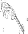
- FIG. 1 illustrates a perspective view of a cutting device 100.
- the cutting device 100 in FIG. 1 is illustrated as a hedge trimmer.
- the hedge trimmer includes a body 110.
- the body 110 includes a handle 112 that allows a user to hold the hedge trimmer.
- the handle 112 further includes a power switch 114 to selectively actuate the hedge trimmer.
- the body 110 houses a drive system (not shown) that includes a drive source and a transmission mechanism.
- the drive system is configured to drive an elongate cutter 120.
- the drive system is mechanically engaged with the elongate cutter 120.
- the elongate cutter 120 includes two blades 130, 140.
- the cutting device 100 employs two blades 130, 140 that move relative to each other.
- the two blades 130, 140 have an identical geometry.
- the blade 130 will be described in detail below and the same description will hold true for the blade 140 as well.
- FIG. 2 illustrates a perspective view of the blade 130.
- the blade 130 is manufactured using a sheet metal with first hardness by laser cutting of the sheet metal.
- the blade 130 formed by the laser cutting further undergoes a heat treatment process.
- the blade 130 has a first end 132 and a second end 134.
- the first end 132 is disposed opposite to the second end 134.
- the first end 132 is a mounting end or a driving end, which is configured to be mechanically engaged to the drive system.
- the second end 134 is a free end, arranged remote from the body 110 of the hedge trimmer.
- the first end 132 and the second end 134 are separated by an elongate portion 136.
- the elongate portion 136 extends along a length of the blade 130.
- the elongate portion 136 is defined along a longitudinal axis X-X'.
- the elongate portion 136 includes edges 150 and edges 160 such that the edges 150 are disposed on one side of the longitudinal axis X-X' and the edges 160 are disposed on opposite side of the longitudinal axis X-X'.
- edges 150 are different in geometry and characteristics to the edges 160.
- the edges 150 are ambos edges of the blade 130, and the edges 160 are the cutting edges of the blade 130.
- the cutting edges perform the cutting action while the ambos edges do not perform the cutting action.
- the ambos edges provide a surface to support or hold a cutting element while the cutting edges perform the cutting action.
- the edges 150 have a larger dimension than the edges 160. Both the edges 150, 160 have a plurality of teeth respectively.
- the laser cutting of the sheet metal to manufacture the blade 130 results in a localized hardness of the edges 150, 160 of the blade 130 after laser cutting such that the localized hardness is greater than the first hardness.
- the edges 160 are grinded such that there might not be any residual localized hardness anymore at the edges 160.
- FIG. 3 illustrates a flowchart of a method 200 for manufacturing at least one of the two blades 130, 140.
- the at least one of the two blades 130, 140 is manufactured using the sheet metal by employing the method 200.
- the blade 130 is assumed to be manufactured using the sheet metal by employing the method 200.
- the method 200 for manufacturing of the blade 130 includes step 210.
- Step 210 includes the laser cutting of the blade 130 from the sheet metal with the first hardness such that the edges 150, 160 of the blade 130 after laser cutting have the localized hardness greater than the first hardness.
- the method 200 of manufacturing the blade 130 further includes step 220.
- Step 220 includes following the laser cutting of the blade 130 by a heat treatment process such that the edges 150, 160 of the blade 130 have a second hardness.
- the second hardness is lesser than the localized hardness resulting from the original laser cutting.
- the temperature of the heat treatment process is less than 400°C, preferably 375°C. Further, duration of the heat treatment process is at least 1.5 hours, preferably 3 hours. Further with this exemplary embodiment, the localized hardness after the laser cutting is 59.5 HRC and the second hardness after the heat treatment process is 54.4 HRC.
- FIG. 4 illustrates an exploded view of the elongate cutter 120.
- the elongate cutter 120 includes the two blades 130, 140.
- the blade 130 as well as the blade 140 includes the first end 132, which is the mounting end or the driving end configured to be mechanically engaged to the drive system. Further, the blade 130 as well as the blade 140 includes the second end 134.
- the blade 130 lies above the blade 140 during an assembly of the elongate cutter 120.
- the blade 140 is rotated 180° relative to the blade 130 during the assembly of the elongate cutter 120 such that each of the edges 160 of the blade 130 are between each of the two consecutive edges 150 of the blade 140. Further, each of the edges 150 of the blade 130 are between each of the two consecutive edges 160 of the blade 140.
- the blade 130 and the blade 140 respectively includes the elongate portion 136.
- the elongate portion 136 of each of the blade 130 and the blade 140 includes a plurality of holes 135 to allow coupling of the blade 130 and the blade 140 using a plurality of fastener sets 170 (including screws, washers, and nuts), an upper bracket 172, and a lower bracket 174.
- the upper bracket 172, and the lower bracket 174 mechanically couples the two blades 130, 140 in a removably manner using a plurality of fastener sets 170.
- the second end 134 of the blade 130 is covered using a side bracket 176 using one of the plurality of fastener sets 170.
- FIG. 5 illustrates an assembled view of the elongate cutter 120 of the hedge trimmer such that the blade 130 lies above the blade 140. Further, the blade 140 is rotated 180 ° relative to the blade 130 such that each of the edges 160 of the blade 130 are between each of the two consecutive edges 150 of the blade 140. Further, each of the edges 150 of the blade 130 are between each of the two consecutive edges 160 of the blade 140. In such an arrangement of the elongate cutter 120, the two blades 130, 140 move relative to each other and the at least one of the two blades 130, 140 perform a linear movement, or a reciprocating movement, or an oscillating movement.
- one blade 130, 140 out of the two blades 130, 140 is fixed and the other blade 130, 140 is movable such that at least one movable blade 130, 140 performs the linear movement.
- FIG. 6 illustrates a perspective view of another cutting device 100.
- the cutting device 100 in FIG. 6 is illustrated as a scissors in a closed state.
- the scissors includes two blades 310, 320.
- the cutting device 100 employs the two blades 310, 320 that move relative to each other.
- the blade 310 has a first edge 330 and the blade 320 has a second edge (not shown).
- the two blades 310, 320 are coupled using a coupler 350 along a pivot point 360.
- the scissors include gripping portions 312, 322 to grip the two blades 310, 320 respectively.
- one blade 310, 320 out of the two blades 310, 320 is fixed and the other blade 310, 320 is movable such that at least one movable blade 310, 320 performs a pivotal movement along the pivot point 360.
- At least one of the two blades 310, 320 is manufactured using the sheet metal by employing the method 200.
- the blade 310 is assumed to be manufactured using the sheet metal by employing the method 200.
- the method 200 for manufacturing the blade 310 includes step 210.
- Step 210 includes the laser cutting of the blade 310 from the sheet metal with the first hardness such that the edge 330 of the blade 310 after laser cutting has the localized hardness greater than the first hardness.
- the method 200 for manufacturing of the blade 310 further includes step 220.
- Step 220 includes following the laser cutting of the blade 310 by the heat treatment process such that the edge 330 of the blade 310 have the second hardness.
- the second hardness is lesser than the localized hardness resulting from the original laser cutting.
- the temperature of the heat treatment process is less than 400°C, preferably 375°C. Further, duration of the heat treatment process is at least 1.5 hours, preferably 3 hours. Further with this exemplary embodiment, the localized hardness after the laser cutting is 59.5 HRC and the second hardness after the heat treatment process is 54.4 HRC.
- FIG. 7 illustrates a perspective view of yet another cutting device 100.
- the cutting device 100 in FIG. 7 is illustrated as a pole pruner.
- the pole pruner includes a longitudinal member 410 having a first end 420 and a second end 430.
- the pole pruner includes two blades 440, 450 coupled to the longitudinal member 410 towards the first end 420.
- the pole pruner includes a handle 432 coupled to the longitudinal member 410 towards the second end 430 such that the movement of the handle 432 away and towards the second end 430 effects the movement of the two blades 440, 450.
- the two blades 440, 450 move away from each other when the handle 432 moves away from the second end 430 and the two blades 440, 450 move towards each other when the handle 432 moves towards the second end 430.
- the cutting device 100 employs the two blades 440, 450 that move relative to each other.
- the two blades 440, 450 includes the edges 460, 470 respectively.
- one blade 440, 450 out of the two blades 440, 450 is fixed and the other blade 440, 450 is movable such that at least one movable blade 440, 450 performs the pivotal movement.
- At least one of the two blades 440, 450 is manufactured using the sheet metal by employing the method 200.
- the blade 440 is assumed to be manufactured using the sheet metal by employing the method 200.
- the method 200 for manufacturing the blade 440 includes step 210.
- Step 210 includes the laser cutting of the blade 440 from the sheet metal with the first hardness such that the edge 460 of the blade 440 after laser cutting has the localized hardness greater than the first hardness.
- the method 200 for manufacturing the blade 440 further includes step 220.
- Step 220 includes following the laser cutting of the blade 440 by the heat treatment process such that the edge 460 of the blade 440 has the second hardness.
- the second hardness is lesser than the localized hardness resulting from the original laser cutting.
- the temperature of the heat treatment process is less than 400°C, preferably 375°C. Further, duration of the heat treatment process is at least 1.5 hours, preferably 3 hours. Further with this exemplary embodiment, the localized hardness after the laser cutting is 59.5 HRC and the second hardness after the heat treatment process is 54.4 HRC.
Landscapes
- Chemical & Material Sciences (AREA)
- Engineering & Computer Science (AREA)
- Mechanical Engineering (AREA)
- Physics & Mathematics (AREA)
- Organic Chemistry (AREA)
- Crystallography & Structural Chemistry (AREA)
- Materials Engineering (AREA)
- Metallurgy (AREA)
- Thermal Sciences (AREA)
- Life Sciences & Earth Sciences (AREA)
- Biodiversity & Conservation Biology (AREA)
- Ecology (AREA)
- Forests & Forestry (AREA)
- Environmental Sciences (AREA)
- Optics & Photonics (AREA)
- Plasma & Fusion (AREA)
- Harvester Elements (AREA)
Abstract
A method (200) of manufacturing a blade (130, 140, 310, 320, 440, 450) includes a laser cutting of the blade (130, 140, 310, 320, 440, 450) from a sheet metal with a first hardness such that edges (150, 160, 330, 460, 470) of the blade (130, 140, 310, 320, 440, 450) after laser cutting have a localized hardness greater than the first hardness. The method (200) is characterized in that the laser cutting of the blade (130, 140, 310, 320, 440, 450) is followed by a heat treatment process such that the edges (150, 160, 330, 460, 470) of the blade (130, 140, 310, 320, 440, 450) have a second hardness. The second hardness is lesser than the localized hardness.
Description
- The present disclosure relates to a cutting device with two blades, and more particularly to a method of manufacturing a blade of the cutting device.
- A cutting device, such as hedge trimmers, secateurs, garden shears, pole pruners, and scissors, may be used for a variety of gardening operations such as cutting, pruning, trimming, and shearing of hedges, shrubs, plants, and the like. The cutting device may include two blades which may move relative to one another. One of the two blades may be a cutting blade and the other blade may be an ambos/ anvil blade. Further, the blades may be manufactured from sheet metal by laser cutting. The laser cutting may automatically result in some sort of heat treatment of the blades near edges of the blades and may result in hardening of the blades at the edges.
- During operation of the cutting device, when the cutting blade may move relative to the ambos blade, the ambos blade may cause wear in the cutting blade such that the grinded edges of the cutting blade may wear-off, and the performance of the cutting device may gradually reduce. To substantially prevent the wear-off of the cutting blade, the laser cutting may be followed by a grinding process for grinding away the hardened edges of the cutting blade and/ or the ambos blade. The hardness of the edges of the cutting blade and/ or the ambos blade may then partially reduce and inch closer in value to the original hardness of the sheet metal (which is softer than the hardness automatically produced during the laser cutting). However, the grinding process for the cutting blade and/ or the ambos blade may be a time-consuming, cumbersome, and expensive process. Hence, an improved, easy, and cost-effective method to manufacture the ambos blade, or both blades in general of the cutting device may be desired that may increase the life of the blades of the cutting device.
- An example of a cutting device is provided in
European Patent Application EP 4,026,420 A1 (hereinafter referred to as '420 reference). The '420 reference provides a cutting device with a first blade and a second blade. The first blade is made by thermal cutting, particularly laser cutting, while the second blade is made by shearing-type processing. The first blade and the second blade after undergoing laser cutting and the shearing-type processing respectively may be subjected to further processing, e.g., sharpening, plane processing, deburring, levelling, cleaning/rust prevention, etc. - In view of the above, it is an objective of the present invention to solve or at least reduce the drawbacks discussed above. The objective is at least partially achieved by a method of manufacturing a blade.
- According to an aspect of the present invention, the method of manufacturing a blade includes a laser cutting of the blade from a sheet metal with a first hardness such that edges of the blade after laser cutting have a localized hardness greater than the first hardness. The method is characterized in that the laser cutting of the blade is followed by a heat treatment process such that the edges of the blade have a second hardness. The second hardness is lesser than the localized hardness.
- Thus, the present disclosure provides an improved method of manufacturing a blade. The method may ensure a longer blade life due to lesser probability of wear of the blade. The method may provide the blade with softer edges, or the edges with hardness approximately similar to the hardness of the sheet metal from which the blade may be manufactured. The method may be quick, reliable, cost-effective, and energy efficient.
- The first hardness according to the present invention may denote the hardness of the sheet metal from which the blade may be manufactured. Further, the localized hardness according to the present invention may denote the hardness of localized area near the laser cut edges of the blade. Further, the second hardness according to the present invention may denote the hardness of localized area near the edges of the blade after the heat treatment process.
- According to an exemplary embodiment of the invention, laser light beam in the laser cutting may be produced by a suitable laser light source such as a carbon dioxide laser, neodymium yttrium-aluminum-garnet laser, and fiber-optic laser.
- According to an exemplary embodiment of the invention, the temperature of the heat treatment process is less than 400°C, preferably 375°C. The heat treatment process may be used to alter the microstructure of the blade, which may be manufactured from sheet metal. The heat treatment process may improve the working life of the blade. The heat treatment process of the blade at 375°C may substantially reduce the hardness of the blade, particularly the hardness of the edges of the blade that may increase due to laser cutting. The heat treatment process may reduce the hardness of the edges of the blade from the localized hardness to the second hardness. In other words, the heat treatment process may warm up the blade and soften the hardness of the blade, particularly blade edges.
- According to an exemplary embodiment of the invention, the heat treatment process may be limited towards the area at or around the localized area where the hardness increases after the laser cutting. According to an exemplary embodiment of the invention, the heat treatment process may be processed on the complete blade.
- According to an exemplary embodiment of the invention, duration of the heat treatment process is at least 1.5 hours, preferably 3 hours. The blade may be subjected to the preferred temperature of 375°C for 3 hours such that the edges of the blade may soften and the hardness of the edges of the blade that may increase due to laser cutting may substantially reduce thereafter.
According to an exemplary embodiment of the invention, the localized hardness is in the range of 58-61 HRC. In one particular embodiment it is 59.5 HRC. In this respect one can in an embodiment expect the second hardness to be in the range of 53-55 HRC. Whereby in a particular embodiment the secondary hardness is 54.4 HRC. - The heat treatment process may substantially reduce the hardness of the edges of the blade from the localized hardness to the second hardness. The heat treatment process may eliminate the need of grinding of the hardened edges of the blade, which may otherwise be a cumbersome, and expensive process.
- According to a further aspect of the present invention, a cutting device employs two blades that move relative to each other. At least one blade of the two blades may be manufactured via the laser cutting followed by the heat treatment process such that the temperature of the heat treatment process is less than 400°C, preferably 375°C and the duration of the heat treatment process is at least 1.5 hours, preferably 3 hours. The cutting device with two blades may find applications in gardening, kitchen, art and craft, amongst other applications.
- According to an exemplary embodiment of the invention, the two blades of the cutting device are coupled to each other using a plurality of fasteners, an upper bracket, and a lower bracket. Further, a plurality of spacers may be provided between the two blades, and/ or the blade and the upper bracket, and/ or the blade and the lower bracket. The plurality of spacers may prevent friction between the blades, and/ or the blade and the upper bracket, and/ or the blade and the lower bracket as per the arrangement of the plurality of spacers.
- According to an exemplary embodiment of the invention, both blades of the cutting device may be manufactured by laser cutting followed by the heat treatment process such as to get a long-lasting performance of the cutting device.
- According to an exemplary embodiment of the invention, one blade is fixed, and the other blade is movable. The movable blade may be a cutting blade. Further, the fixed blade may be an anvil or ambos blade and may provide flat surface to support cutting, for example, of hedges, shrubs, etc., by the cutting blade. The cutting blade may close against the flat surface of the anvil or ambos blade.
- According to an exemplary embodiment of the invention, at least one movable blade performs a pivotable movement. The at least one blade may be movable to perform an anvil-type cutting, or the bypass type cutting. For example, the cutting device may be a secateurs having a pair of pivoted handles and may have a single movable cutting blade that closes against a flat surface to perform the anvil-type cutting.
- According to an exemplary embodiment of the invention, at least one movable blade performs a linear movement. The at least one movable blade may perform a reciprocating, or oscillating type movement to allow the cutting device to perform the cutting of hedges, shrubs, plants, and the like. The at least one blade may be movable using the power of a motor, an engine, or any other propulsion means.
- According to an exemplary embodiment of the invention, the cutting device is a hedge trimmer. The hedge trimmer is a gardening tool that may be used for trimming (cutting, pruning) hedges or solitary shrubs (bushes). The hedge trimmer may be a portable and hand-held cutting device. The hedge trimmer may be powered by a drive source, such as the motor, or the engine.
- According to an exemplary embodiment of the invention, the cutting device is scissors. The scissors may support bypass cutting such that two cutting blades of the scissors may move to an overlapping position while performing cutting action. The scissors may be manual, or electrically powered scissors. It is obvious to the one skilled in the art that there may be other possible embodiments that exhibit a cutting arrangement similar to the scissors, such as, with secateurs or shears, in particular garden shears.
- Before discussing the invention with the help of the drawings the invention will be briefly discussed in general. A method is developed for manufacturing at least one blade of a cutting device that employs two blades. The at least one blade may be manufactured by laser cutting of the at least one blade from sheet metal. After the laser cutting, the at least one blade may be heat treated up to 375° C for a time span of 1.5 to 3 hours in a heating oven. The heat treatment may be more of a warming up process and not at all a hardening process. The warming up process may result in softening of the hardness, in particular any local hardness arising from laser cutting, of the at least one blade.
- The method according to the present invention may ensure a long-lasting blade performance with good cutting edges. The method according to the present invention may allow avoidance of a significant wear-off process of the at least one blade manufactured by the method of this invention without any need for expensive scraping off of the laser cut edges.
- According to an exemplary embodiment of the invention, the method for manufacturing at least one blade of the cutting device may involve laser cutting followed by the heat treatment. The hardness difference over the whole at least one blade manufactured by the method of the invention may not be more than 3 HRC.
- Other features and aspects of this invention will be apparent from the following description and the accompanying drawings.
- The invention will be described in more detail with reference to the enclosed drawings, wherein:
-
FIG. 1 illustrates a perspective view of a hedge trimmer, in accordance with an exemplary embodiment of the present disclosure; -
FIG. 2 illustrates a perspective view of a blade of a hedge trimmer, in accordance with an exemplary embodiment of the present disclosure; -
FIG. 3 illustrates a flowchart of a method for manufacturing a blade of a cutting device, in accordance with an exemplary embodiment of the present disclosure; -
FIG. 4 illustrates an exploded view of an elongate cutter of a hedge trimmer, in accordance with an exemplary embodiment of the present disclosure; -
FIG. 5 illustrates an assembled view of an elongate cutter of a hedge trimmer, in accordance with an exemplary embodiment of the present disclosure; -
FIG. 6 illustrates a perspective view of a scissors, in accordance with an exemplary embodiment of the present disclosure; and -
FIG. 7 illustrates a perspective view of a pole pruner, in accordance with an exemplary embodiment of the present disclosure. - The present invention will be described more fully hereinafter with reference to the accompanying drawings, in which example embodiments of the invention incorporating one or more aspects of the present invention are shown. This invention may, however, be embodied in many different forms and should not be construed as limited to the embodiments set forth herein; rather, these embodiments are provided so that this disclosure will be thorough and complete, and will fully convey the scope of the invention to those skilled in the art. For example, one or more aspects of the present invention may be utilized in other embodiments and even other types of structures and/or methods. In the drawings, like numbers refer to like elements.
- Certain terminology is used herein for convenience only and is not to be taken as a limitation on the invention. For example, "upper", "lower", "front", "rear", "side", "longitudinal", "lateral", "transverse", "upwards", "downwards", "forward", "backward", "sideward", "left," "right," "horizontal," "vertical," "upward", "inner", "outer", "inward", "outward", "top", "bottom", "higher", "above", "below", "central", "middle", "intermediate", "between", "end", "adjacent", "proximate", "near", "distal", "remote", "radial", "circumferential", or the like, merely describe the configuration shown in the Figures. Indeed, the components may be oriented in any direction and the terminology, therefore, should be understood as encompassing such variations unless specified otherwise.
-
FIG. 1 illustrates a perspective view of acutting device 100. Thecutting device 100 inFIG. 1 is illustrated as a hedge trimmer. The hedge trimmer includes abody 110. Thebody 110 includes ahandle 112 that allows a user to hold the hedge trimmer. Thehandle 112 further includes apower switch 114 to selectively actuate the hedge trimmer. Further, thebody 110 houses a drive system (not shown) that includes a drive source and a transmission mechanism. The drive system is configured to drive anelongate cutter 120. The drive system is mechanically engaged with theelongate cutter 120. Theelongate cutter 120 includes twoblades cutting device 100 employs twoblades blades blade 130 will be described in detail below and the same description will hold true for theblade 140 as well. -
FIG. 2 illustrates a perspective view of theblade 130. Theblade 130 is manufactured using a sheet metal with first hardness by laser cutting of the sheet metal. Theblade 130 formed by the laser cutting further undergoes a heat treatment process. Theblade 130 has afirst end 132 and asecond end 134. Thefirst end 132 is disposed opposite to thesecond end 134. Thefirst end 132 is a mounting end or a driving end, which is configured to be mechanically engaged to the drive system. Thesecond end 134 is a free end, arranged remote from thebody 110 of the hedge trimmer. Thefirst end 132 and thesecond end 134 are separated by anelongate portion 136. Theelongate portion 136 extends along a length of theblade 130. Theelongate portion 136 is defined along a longitudinal axis X-X'. Theelongate portion 136 includesedges 150 andedges 160 such that theedges 150 are disposed on one side of the longitudinal axis X-X' and theedges 160 are disposed on opposite side of the longitudinal axis X-X'. - Further, the
edges 150 are different in geometry and characteristics to theedges 160. Theedges 150 are ambos edges of theblade 130, and theedges 160 are the cutting edges of theblade 130. The cutting edges perform the cutting action while the ambos edges do not perform the cutting action. The ambos edges provide a surface to support or hold a cutting element while the cutting edges perform the cutting action. Theedges 150 have a larger dimension than theedges 160. Both theedges - Further, the laser cutting of the sheet metal to manufacture the
blade 130 results in a localized hardness of theedges blade 130 after laser cutting such that the localized hardness is greater than the first hardness. Theedges 160 are grinded such that there might not be any residual localized hardness anymore at theedges 160. -
FIG. 3 illustrates a flowchart of amethod 200 for manufacturing at least one of the twoblades blades method 200. For understanding of the present invention, theblade 130 is assumed to be manufactured using the sheet metal by employing themethod 200. Themethod 200 for manufacturing of theblade 130 includesstep 210. Step 210 includes the laser cutting of theblade 130 from the sheet metal with the first hardness such that theedges blade 130 after laser cutting have the localized hardness greater than the first hardness. Themethod 200 of manufacturing theblade 130 further includesstep 220. Step 220 includes following the laser cutting of theblade 130 by a heat treatment process such that theedges blade 130 have a second hardness. The second hardness is lesser than the localized hardness resulting from the original laser cutting. The temperature of the heat treatment process is less than 400°C, preferably 375°C. Further, duration of the heat treatment process is at least 1.5 hours, preferably 3 hours. Further with this exemplary embodiment, the localized hardness after the laser cutting is 59.5 HRC and the second hardness after the heat treatment process is 54.4 HRC. -
FIG. 4 illustrates an exploded view of theelongate cutter 120. Theelongate cutter 120 includes the twoblades blade 130 as well as theblade 140 includes thefirst end 132, which is the mounting end or the driving end configured to be mechanically engaged to the drive system. Further, theblade 130 as well as theblade 140 includes thesecond end 134. Theblade 130 lies above theblade 140 during an assembly of theelongate cutter 120. Theblade 140 is rotated 180° relative to theblade 130 during the assembly of theelongate cutter 120 such that each of theedges 160 of theblade 130 are between each of the twoconsecutive edges 150 of theblade 140. Further, each of theedges 150 of theblade 130 are between each of the twoconsecutive edges 160 of theblade 140. - Further, the
blade 130 and theblade 140 respectively includes theelongate portion 136. Theelongate portion 136 of each of theblade 130 and theblade 140 includes a plurality ofholes 135 to allow coupling of theblade 130 and theblade 140 using a plurality of fastener sets 170 (including screws, washers, and nuts), anupper bracket 172, and alower bracket 174. Theupper bracket 172, and thelower bracket 174 mechanically couples the twoblades second end 134 of theblade 130 is covered using aside bracket 176 using one of the plurality of fastener sets 170. -
FIG. 5 illustrates an assembled view of theelongate cutter 120 of the hedge trimmer such that theblade 130 lies above theblade 140. Further, theblade 140 is rotated 180° relative to theblade 130 such that each of theedges 160 of theblade 130 are between each of the twoconsecutive edges 150 of theblade 140. Further, each of theedges 150 of theblade 130 are between each of the twoconsecutive edges 160 of theblade 140. In such an arrangement of theelongate cutter 120, the twoblades blades - Further, in another embodiment, one
blade blades other blade movable blade -
FIG. 6 illustrates a perspective view of anothercutting device 100. Thecutting device 100 inFIG. 6 is illustrated as a scissors in a closed state. The scissors includes twoblades cutting device 100 employs the twoblades blade 310 has afirst edge 330 and theblade 320 has a second edge (not shown). The twoblades coupler 350 along apivot point 360. Further, the scissors include grippingportions blades - In another embodiment, one
blade blades other blade movable blade pivot point 360. - Further, at least one of the two
blades method 200. For understanding of the present invention, theblade 310 is assumed to be manufactured using the sheet metal by employing themethod 200. Themethod 200 for manufacturing theblade 310 includesstep 210. Step 210 includes the laser cutting of theblade 310 from the sheet metal with the first hardness such that theedge 330 of theblade 310 after laser cutting has the localized hardness greater than the first hardness. Themethod 200 for manufacturing of theblade 310 further includesstep 220. Step 220 includes following the laser cutting of theblade 310 by the heat treatment process such that theedge 330 of theblade 310 have the second hardness. The second hardness is lesser than the localized hardness resulting from the original laser cutting. The temperature of the heat treatment process is less than 400°C, preferably 375°C. Further, duration of the heat treatment process is at least 1.5 hours, preferably 3 hours. Further with this exemplary embodiment, the localized hardness after the laser cutting is 59.5 HRC and the second hardness after the heat treatment process is 54.4 HRC. -
FIG. 7 illustrates a perspective view of yet anothercutting device 100. Thecutting device 100 inFIG. 7 is illustrated as a pole pruner. The pole pruner includes alongitudinal member 410 having afirst end 420 and asecond end 430. The pole pruner includes twoblades longitudinal member 410 towards thefirst end 420. Further, the pole pruner includes ahandle 432 coupled to thelongitudinal member 410 towards thesecond end 430 such that the movement of thehandle 432 away and towards thesecond end 430 effects the movement of the twoblades blades handle 432 moves away from thesecond end 430 and the twoblades handle 432 moves towards thesecond end 430. In other words, thecutting device 100 employs the twoblades blades edges - In another embodiment, one
blade blades other blade movable blade - Further, at least one of the two
blades method 200. For understanding of the present invention, theblade 440 is assumed to be manufactured using the sheet metal by employing themethod 200. Themethod 200 for manufacturing theblade 440 includesstep 210. Step 210 includes the laser cutting of theblade 440 from the sheet metal with the first hardness such that theedge 460 of theblade 440 after laser cutting has the localized hardness greater than the first hardness. Themethod 200 for manufacturing theblade 440 further includesstep 220. Step 220 includes following the laser cutting of theblade 440 by the heat treatment process such that theedge 460 of theblade 440 has the second hardness. The second hardness is lesser than the localized hardness resulting from the original laser cutting. The temperature of the heat treatment process is less than 400°C, preferably 375°C. Further, duration of the heat treatment process is at least 1.5 hours, preferably 3 hours. Further with this exemplary embodiment, the localized hardness after the laser cutting is 59.5 HRC and the second hardness after the heat treatment process is 54.4 HRC. - In the drawings and specification, there have been disclosed exemplary embodiments and examples of the invention and, although specific terms are employed, they are used in a generic and descriptive sense only and not for the purpose of limitation of the scope of the invention being set forth in the following claims.
-
- 100
- Cutting Device
- 110
- Body
- 112
- Handle
- 114
- Power Switch
- 120
- Elongate Cutter
- 130
- Blade
- 132
- First End
- 134
- Second End
- 135
- Holes
- 136
- Elongate Portion
- 140
- Blade
- 150
- Edges
- 160
- Edges
- 170
- Fastener sets
- 172
- Upper Bracket
- 174
- Lower Bracket
- 176
- Side Bracket
- 200
- Method
- 210
- Step
- 220
- Step
- 310
- Blade
- 312
- Gripping Portion
- 320
- Blade
- 322
- Gripping Portion
- 330
- First Edge
- 350
- Coupler
- 360
- Pivot Point
- 410
- Longitudinal Member
- 420
- First End
- 430
- Second End
- 432
- Handle
- 440
- Blade
- 450
- Blade
- 460
- Edges
- 470
- Edges
- X-X'
- Longitudinal Axis
Claims (11)
- A method (200) of manufacturing a blade (130, 140, 310, 320, 440, 450), comprising:
a laser cutting of the blade (130, 140, 310, 320, 440, 450) from a sheet metal with a first hardness, wherein edges (150, 160, 330, 460, 470) of the blade (130, 140, 310, 320, 440, 450) after laser cutting have a localized hardness greater than the first hardness;
characterized in that:
the laser cutting of the blade (130, 140, 310, 320, 440, 450) is followed by a heat treatment process such that the edges (150, 160, 330, 460, 470) of the blade (130, 140, 310, 320, 440, 450) have a second hardness, wherein the second hardness is lesser than the localized hardness. - The method (200) according to claim 1, wherein temperature of the heat treatment process is less than 400°C, preferably 375°C.
- The method (200) according to any of the claims 1 or 2, wherein duration of the heat treatment process is at least 1.5 hours, preferably 3 hours.
- The method (200) according to claim 1, wherein the localized hardness is in the range of 58-61 HRC.
- The method (200) according to claim 4, wherein the second hardness is the range of 53-55 HRC.
- A cutting device (100) employing two blades (130, 140, 310, 320, 440, 450) that move relative to each other with at least one blade (130, 140, 310, 320, 440, 450) manufactured using the method (200) of claims 1-5.
- The cutting device (100) according to claim 6, wherein one blade (130, 140, 310, 320, 440, 450) is fixed, and the other blade (130, 140, 310, 320, 440, 450) is movable.
- The cutting device (100) according to claim 7, wherein at least one movable blade (310, 320, 440, 450) performs a pivotable movement.
- The cutting device (100) according to claim 7, wherein at least one movable blade (130, 140) performs a linear movement.
- The cutting device (100) according to any of the claims 7 or 9, wherein the cutting device (100) is a hedge trimmer.
- The cutting device (100) according to any of the claims 7 or 8, wherein the cutting device (100) is scissors.
Priority Applications (2)
| Application Number | Priority Date | Filing Date | Title |
|---|---|---|---|
| EP23181440.1A EP4484583A1 (en) | 2023-06-26 | 2023-06-26 | A method of manufacturing blades of a cutting device |
| CN202410820804.XA CN119188197A (en) | 2023-06-26 | 2024-06-24 | Method for manufacturing a blade for a cutting device |
Applications Claiming Priority (1)
| Application Number | Priority Date | Filing Date | Title |
|---|---|---|---|
| EP23181440.1A EP4484583A1 (en) | 2023-06-26 | 2023-06-26 | A method of manufacturing blades of a cutting device |
Publications (1)
| Publication Number | Publication Date |
|---|---|
| EP4484583A1 true EP4484583A1 (en) | 2025-01-01 |
Family
ID=87047749
Family Applications (1)
| Application Number | Title | Priority Date | Filing Date |
|---|---|---|---|
| EP23181440.1A Pending EP4484583A1 (en) | 2023-06-26 | 2023-06-26 | A method of manufacturing blades of a cutting device |
Country Status (2)
| Country | Link |
|---|---|
| EP (1) | EP4484583A1 (en) |
| CN (1) | CN119188197A (en) |
Citations (4)
| Publication number | Priority date | Publication date | Assignee | Title |
|---|---|---|---|---|
| DE3612915A1 (en) * | 1986-04-17 | 1987-10-22 | Scintilla Ag | CUTTING BLADES WITH TEETH, IN PARTICULAR HEDGE TRIMMING KNIVES AND METHOD FOR THE PRODUCTION THEREOF |
| JP4280616B2 (en) * | 2003-12-10 | 2009-06-17 | 日新製鋼株式会社 | Horticulture blade |
| CN112265020A (en) * | 2020-10-09 | 2021-01-26 | 厦门昱祥工业有限公司 | Scissors for pneumatic scissors and manufacturing method thereof |
| EP4026420A1 (en) | 2021-01-11 | 2022-07-13 | Techtronic Cordless GP | Cutter apparatus, cutting tool, and method for manufacturing cutter apparatus |
-
2023
- 2023-06-26 EP EP23181440.1A patent/EP4484583A1/en active Pending
-
2024
- 2024-06-24 CN CN202410820804.XA patent/CN119188197A/en active Pending
Patent Citations (4)
| Publication number | Priority date | Publication date | Assignee | Title |
|---|---|---|---|---|
| DE3612915A1 (en) * | 1986-04-17 | 1987-10-22 | Scintilla Ag | CUTTING BLADES WITH TEETH, IN PARTICULAR HEDGE TRIMMING KNIVES AND METHOD FOR THE PRODUCTION THEREOF |
| JP4280616B2 (en) * | 2003-12-10 | 2009-06-17 | 日新製鋼株式会社 | Horticulture blade |
| CN112265020A (en) * | 2020-10-09 | 2021-01-26 | 厦门昱祥工业有限公司 | Scissors for pneumatic scissors and manufacturing method thereof |
| EP4026420A1 (en) | 2021-01-11 | 2022-07-13 | Techtronic Cordless GP | Cutter apparatus, cutting tool, and method for manufacturing cutter apparatus |
Non-Patent Citations (1)
| Title |
|---|
| N.A.: "Getting started in the garden", 5 January 2016 (2016-01-05), XP093098797, Retrieved from the Internet <URL:https://wolfgarten-tools.co.uk/media/2882/wolf-garten-catalogue-2022.pdf> [retrieved on 20231107] * |
Also Published As
| Publication number | Publication date |
|---|---|
| CN119188197A (en) | 2024-12-27 |
Similar Documents
| Publication | Publication Date | Title |
|---|---|---|
| CA2155805C (en) | Hedge trimmer with combination shearing and sawing blade assembly | |
| KR101681629B1 (en) | Mechanized portable electric tool with two shafts | |
| EP3076778B1 (en) | Dual direction cutting device | |
| US8910386B2 (en) | Multiple cut zone blade assembly for a hand operated cutting tool | |
| US5398415A (en) | Cutter with gripper | |
| US20120037275A1 (en) | Tree processing head | |
| US20100162574A1 (en) | Electric pruner | |
| JP7284005B2 (en) | Reciprocating cutting blade device | |
| JP4405579B1 (en) | Circular hollow rotary blade parts for tree modeling | |
| US2748477A (en) | Hedge trimmer | |
| CN119188197A (en) | Method for manufacturing a blade for a cutting device | |
| GB2384678A (en) | Hedge trimming and shaping device | |
| CN118633439B (en) | A fruit thinner for planting | |
| US4602432A (en) | Shear with offset cutting edge | |
| WO2019170271A1 (en) | Lopper with additional cutting edge | |
| GB2383249A (en) | Horticultural hedgetrimmer and saw | |
| RU178799U1 (en) | SECTOR GARDEN | |
| JPH0522051Y2 (en) | ||
| WO2021024580A1 (en) | Reciprocating cutting blade device and brush cutter | |
| SU1752171A3 (en) | Pruner | |
| RU52661U1 (en) | MOWER | |
| SU1692375A1 (en) | Pruner | |
| US1025641A (en) | Hedge-pruner. | |
| US876915A (en) | Vegetable cutter and trimmer. | |
| KR102282824B1 (en) | fruit tree pruning scissors |
Legal Events
| Date | Code | Title | Description |
|---|---|---|---|
| PUAI | Public reference made under article 153(3) epc to a published international application that has entered the european phase |
Free format text: ORIGINAL CODE: 0009012 |
|
| STAA | Information on the status of an ep patent application or granted ep patent |
Free format text: STATUS: REQUEST FOR EXAMINATION WAS MADE |
|
| 17P | Request for examination filed |
Effective date: 20240627 |
|
| AK | Designated contracting states |
Kind code of ref document: A1 Designated state(s): AL AT BE BG CH CY CZ DE DK EE ES FI FR GB GR HR HU IE IS IT LI LT LU LV MC ME MK MT NL NO PL PT RO RS SE SI SK SM TR |