EP4484317A1 - Article carrier and blank therefor - Google Patents
Article carrier and blank therefor Download PDFInfo
- Publication number
- EP4484317A1 EP4484317A1 EP24185852.1A EP24185852A EP4484317A1 EP 4484317 A1 EP4484317 A1 EP 4484317A1 EP 24185852 A EP24185852 A EP 24185852A EP 4484317 A1 EP4484317 A1 EP 4484317A1
- Authority
- EP
- European Patent Office
- Prior art keywords
- panel
- line
- partition
- fold line
- panels
- Prior art date
- Legal status (The legal status is an assumption and is not a legal conclusion. Google has not performed a legal analysis and makes no representation as to the accuracy of the status listed.)
- Granted
Links
Images




Classifications
-
- B—PERFORMING OPERATIONS; TRANSPORTING
- B65—CONVEYING; PACKING; STORING; HANDLING THIN OR FILAMENTARY MATERIAL
- B65D—CONTAINERS FOR STORAGE OR TRANSPORT OF ARTICLES OR MATERIALS, e.g. BAGS, BARRELS, BOTTLES, BOXES, CANS, CARTONS, CRATES, DRUMS, JARS, TANKS, HOPPERS, FORWARDING CONTAINERS; ACCESSORIES, CLOSURES, OR FITTINGS THEREFOR; PACKAGING ELEMENTS; PACKAGES
- B65D71/00—Bundles of articles held together by packaging elements for convenience of storage or transport, e.g. portable segregating carrier for plural receptacles such as beer cans or pop bottles; Bales of material
- B65D71/0003—Tray-like elements provided with handles, for storage or transport of several articles, e.g. bottles, tins, jars
- B65D71/0022—Tray-like elements provided with handles, for storage or transport of several articles, e.g. bottles, tins, jars formed by folding or erecting one blank, and provided with vertical partitions
-
- B—PERFORMING OPERATIONS; TRANSPORTING
- B65—CONVEYING; PACKING; STORING; HANDLING THIN OR FILAMENTARY MATERIAL
- B65D—CONTAINERS FOR STORAGE OR TRANSPORT OF ARTICLES OR MATERIALS, e.g. BAGS, BARRELS, BOTTLES, BOXES, CANS, CARTONS, CRATES, DRUMS, JARS, TANKS, HOPPERS, FORWARDING CONTAINERS; ACCESSORIES, CLOSURES, OR FITTINGS THEREFOR; PACKAGING ELEMENTS; PACKAGES
- B65D71/00—Bundles of articles held together by packaging elements for convenience of storage or transport, e.g. portable segregating carrier for plural receptacles such as beer cans or pop bottles; Bales of material
- B65D71/0003—Tray-like elements provided with handles, for storage or transport of several articles, e.g. bottles, tins, jars
-
- B—PERFORMING OPERATIONS; TRANSPORTING
- B65—CONVEYING; PACKING; STORING; HANDLING THIN OR FILAMENTARY MATERIAL
- B65D—CONTAINERS FOR STORAGE OR TRANSPORT OF ARTICLES OR MATERIALS, e.g. BAGS, BARRELS, BOTTLES, BOXES, CANS, CARTONS, CRATES, DRUMS, JARS, TANKS, HOPPERS, FORWARDING CONTAINERS; ACCESSORIES, CLOSURES, OR FITTINGS THEREFOR; PACKAGING ELEMENTS; PACKAGES
- B65D2571/00—Bundles of articles held together by packaging elements for convenience of storage or transport, e.g. portable segregating carrier for plural receptacles such as beer cans, pop bottles; Bales of material
- B65D2571/00123—Bundling wrappers or trays
- B65D2571/00129—Wrapper locking means
- B65D2571/00135—Wrapper locking means integral with the wrapper
- B65D2571/00141—Wrapper locking means integral with the wrapper glued
-
- B—PERFORMING OPERATIONS; TRANSPORTING
- B65—CONVEYING; PACKING; STORING; HANDLING THIN OR FILAMENTARY MATERIAL
- B65D—CONTAINERS FOR STORAGE OR TRANSPORT OF ARTICLES OR MATERIALS, e.g. BAGS, BARRELS, BOTTLES, BOXES, CANS, CARTONS, CRATES, DRUMS, JARS, TANKS, HOPPERS, FORWARDING CONTAINERS; ACCESSORIES, CLOSURES, OR FITTINGS THEREFOR; PACKAGING ELEMENTS; PACKAGES
- B65D2571/00—Bundles of articles held together by packaging elements for convenience of storage or transport, e.g. portable segregating carrier for plural receptacles such as beer cans, pop bottles; Bales of material
- B65D2571/00123—Bundling wrappers or trays
- B65D2571/00333—Partitions, i.e. elements contacting a major part of each aarticle or extending across the whole length of the wrapper
- B65D2571/0037—Partitions, i.e. elements contacting a major part of each aarticle or extending across the whole length of the wrapper extending from at least a side wall
- B65D2571/00376—Squarings or the like
- B65D2571/00388—Two rows of more than two cells
-
- B—PERFORMING OPERATIONS; TRANSPORTING
- B65—CONVEYING; PACKING; STORING; HANDLING THIN OR FILAMENTARY MATERIAL
- B65D—CONTAINERS FOR STORAGE OR TRANSPORT OF ARTICLES OR MATERIALS, e.g. BAGS, BARRELS, BOTTLES, BOXES, CANS, CARTONS, CRATES, DRUMS, JARS, TANKS, HOPPERS, FORWARDING CONTAINERS; ACCESSORIES, CLOSURES, OR FITTINGS THEREFOR; PACKAGING ELEMENTS; PACKAGES
- B65D2571/00—Bundles of articles held together by packaging elements for convenience of storage or transport, e.g. portable segregating carrier for plural receptacles such as beer cans, pop bottles; Bales of material
- B65D2571/00123—Bundling wrappers or trays
- B65D2571/00432—Handles or suspending means
- B65D2571/00438—Holes
- B65D2571/0045—Holes for hands
-
- B—PERFORMING OPERATIONS; TRANSPORTING
- B65—CONVEYING; PACKING; STORING; HANDLING THIN OR FILAMENTARY MATERIAL
- B65D—CONTAINERS FOR STORAGE OR TRANSPORT OF ARTICLES OR MATERIALS, e.g. BAGS, BARRELS, BOTTLES, BOXES, CANS, CARTONS, CRATES, DRUMS, JARS, TANKS, HOPPERS, FORWARDING CONTAINERS; ACCESSORIES, CLOSURES, OR FITTINGS THEREFOR; PACKAGING ELEMENTS; PACKAGES
- B65D2571/00—Bundles of articles held together by packaging elements for convenience of storage or transport, e.g. portable segregating carrier for plural receptacles such as beer cans, pop bottles; Bales of material
- B65D2571/00123—Bundling wrappers or trays
- B65D2571/00432—Handles or suspending means
- B65D2571/00456—Handles or suspending means integral with the wrapper
- B65D2571/00475—Handles or suspending means integral with the wrapper and extending ion a substantially vertical plane
- B65D2571/00487—Handles or suspending means integral with the wrapper and extending ion a substantially vertical plane and formed integrally with a partition
-
- B—PERFORMING OPERATIONS; TRANSPORTING
- B65—CONVEYING; PACKING; STORING; HANDLING THIN OR FILAMENTARY MATERIAL
- B65D—CONTAINERS FOR STORAGE OR TRANSPORT OF ARTICLES OR MATERIALS, e.g. BAGS, BARRELS, BOTTLES, BOXES, CANS, CARTONS, CRATES, DRUMS, JARS, TANKS, HOPPERS, FORWARDING CONTAINERS; ACCESSORIES, CLOSURES, OR FITTINGS THEREFOR; PACKAGING ELEMENTS; PACKAGES
- B65D2571/00—Bundles of articles held together by packaging elements for convenience of storage or transport, e.g. portable segregating carrier for plural receptacles such as beer cans, pop bottles; Bales of material
- B65D2571/00123—Bundling wrappers or trays
- B65D2571/00432—Handles or suspending means
- B65D2571/00518—Handles or suspending means with reinforcements
- B65D2571/00524—Handles or suspending means with reinforcements integral
-
- B—PERFORMING OPERATIONS; TRANSPORTING
- B65—CONVEYING; PACKING; STORING; HANDLING THIN OR FILAMENTARY MATERIAL
- B65D—CONTAINERS FOR STORAGE OR TRANSPORT OF ARTICLES OR MATERIALS, e.g. BAGS, BARRELS, BOTTLES, BOXES, CANS, CARTONS, CRATES, DRUMS, JARS, TANKS, HOPPERS, FORWARDING CONTAINERS; ACCESSORIES, CLOSURES, OR FITTINGS THEREFOR; PACKAGING ELEMENTS; PACKAGES
- B65D2571/00—Bundles of articles held together by packaging elements for convenience of storage or transport, e.g. portable segregating carrier for plural receptacles such as beer cans, pop bottles; Bales of material
- B65D2571/00123—Bundling wrappers or trays
- B65D2571/00648—Elements used to form the wrapper
- B65D2571/00654—Blanks
- B65D2571/0066—Blanks formed from one single sheet
-
- B—PERFORMING OPERATIONS; TRANSPORTING
- B65—CONVEYING; PACKING; STORING; HANDLING THIN OR FILAMENTARY MATERIAL
- B65D—CONTAINERS FOR STORAGE OR TRANSPORT OF ARTICLES OR MATERIALS, e.g. BAGS, BARRELS, BOTTLES, BOXES, CANS, CARTONS, CRATES, DRUMS, JARS, TANKS, HOPPERS, FORWARDING CONTAINERS; ACCESSORIES, CLOSURES, OR FITTINGS THEREFOR; PACKAGING ELEMENTS; PACKAGES
- B65D2571/00—Bundles of articles held together by packaging elements for convenience of storage or transport, e.g. portable segregating carrier for plural receptacles such as beer cans, pop bottles; Bales of material
- B65D2571/00123—Bundling wrappers or trays
- B65D2571/00709—Shape of the formed wrapper, i.e. shape of each formed element if the wrapper is made from more than one element
- B65D2571/00722—Shape of the formed wrapper, i.e. shape of each formed element if the wrapper is made from more than one element tubular with end walls, e.g. walls not extending on the whole end surface
- B65D2571/00753—Shape of the formed wrapper, i.e. shape of each formed element if the wrapper is made from more than one element tubular with end walls, e.g. walls not extending on the whole end surface the end walls being closed by interlocking
-
- B—PERFORMING OPERATIONS; TRANSPORTING
- B65—CONVEYING; PACKING; STORING; HANDLING THIN OR FILAMENTARY MATERIAL
- B65D—CONTAINERS FOR STORAGE OR TRANSPORT OF ARTICLES OR MATERIALS, e.g. BAGS, BARRELS, BOTTLES, BOXES, CANS, CARTONS, CRATES, DRUMS, JARS, TANKS, HOPPERS, FORWARDING CONTAINERS; ACCESSORIES, CLOSURES, OR FITTINGS THEREFOR; PACKAGING ELEMENTS; PACKAGES
- B65D2571/00—Bundles of articles held together by packaging elements for convenience of storage or transport, e.g. portable segregating carrier for plural receptacles such as beer cans, pop bottles; Bales of material
- B65D2571/00123—Bundling wrappers or trays
- B65D2571/00833—Other details of wrappers
- B65D2571/0087—Special features for machine processing, e.g. gripper apertures
-
- B—PERFORMING OPERATIONS; TRANSPORTING
- B65—CONVEYING; PACKING; STORING; HANDLING THIN OR FILAMENTARY MATERIAL
- B65D—CONTAINERS FOR STORAGE OR TRANSPORT OF ARTICLES OR MATERIALS, e.g. BAGS, BARRELS, BOTTLES, BOXES, CANS, CARTONS, CRATES, DRUMS, JARS, TANKS, HOPPERS, FORWARDING CONTAINERS; ACCESSORIES, CLOSURES, OR FITTINGS THEREFOR; PACKAGING ELEMENTS; PACKAGES
- B65D2571/00—Bundles of articles held together by packaging elements for convenience of storage or transport, e.g. portable segregating carrier for plural receptacles such as beer cans, pop bottles; Bales of material
- B65D2571/00123—Bundling wrappers or trays
- B65D2571/00833—Other details of wrappers
- B65D2571/00932—Flattenable or foldable packages
Definitions
- the present invention relates to carriers and to blanks for forming the same. More specifically, but not exclusively, the invention relates to a carrier having a partition structure feature defining cells or compartments within an interior of a carrier of the basket-style.
- the blank from which the carrier is formed can be readily assembled into a carrier in a simple and efficient manner.
- the present invention seeks to provide an improvement in the field of cartons, typically formed from paperboard or the like.
- a first aspect of the invention provides an article carrier for packaging one or more articles.
- the article carrier comprises a plurality of primary panels for forming a tubular structure.
- the plurality of primary panels includes a first panel and a second panel.
- the first and second panels are spaced apart from, and disposed in opposition to, each other.
- the article carrier further comprises a partition structure extending between the first and second panels.
- the partition structure comprises a first partition panel and a first securing panel.
- the first partition panel is formed at least in part from the first panel and is hingedly connected to the first panel by a first fold line.
- the first securing panel is formed from one of the first panel and the first partition panel and is foldably connected to the first partition panel by a joint portion of the first partition panel.
- the first securing panel is defined, at least in part, by a cut line when the article carrier is in a blank form.
- the cut line has a terminal end proximate to a free end of the first partition panel.
- the cut line defines a notional line passing through the terminal end of the cut line.
- the notional line is parallel to the first fold line.
- the joint portion comprises a weakened line spaced apart from the notional line.
- the joint portion comprises an area of the partition panel extending between the notional line and the free end of the partition panel and wherein the weakened line is spaced apart from the free end.
- the weakened line is disposed or arranged parallel to the notional line.
- the weakened line is formed from one or more elements selected from the group consisting of a perforation, at least one cut, at least one half-cut, at least one opening, at least one crease line.
- the free end of the partition panel lies upon a first hinged connection between the first panel and a third panel.
- the partition structure comprises a second partition panel and a second securing panel.
- the second partition panel may be formed at least in part from the first panel and hingedly connected to the first panel by a second fold line.
- the second securing panel may be hingedly connected to the second partition panel by a third fold line.
- the third fold line is spaced apart from the second fold line by a first distance.
- the first distance L1 may be substantially equal to the distance between the first and second panels.
- the second securing panel is defined at least in part by a cut line when the carrier is in a blank form.
- the cut line may have at least one terminal end lying on the third fold line.
- the first fold line may be spaced apart from the notional line by a second distance. The second distance may be less than the first distance.
- a portion of the second securing panel is struck from the partition panel.
- a second aspect of the invention provides a blank for forming an article carrier.
- the blank comprises a plurality of primary panels for forming walls of a tubular structure.
- the plurality of primary panels includes a first panel and a second panel.
- the first and second panels are configured to be spaced apart from, and disposed in opposition to, each other in a set-up carrier.
- the blank further comprises a plurality of secondary panels for forming a partition structure configured to extend between the first and second panels in a set-up carrier.
- the plurality of secondary panels comprises a first partition panel and a first securing panel.
- the first partition panel is formed at least in part from the first panel and hingedly connected to the first panel by a first fold line.
- the first securing panel is formed from one of the first panel and the first partition panel.
- the first securing panel is foldably connected to the first partition panel by a joint portion of the first partition panel.
- the first securing panel is defined, at least in part, by a cut line having a terminal end proximate to a free end of the first partition panel.
- the cut line defines a notional line passing through the terminal end of the cut line.
- the notional line is parallel to the first fold line.
- the joint portion comprises a weakened line spaced apart from the notional line.
- the joint portion comprises an area of the first partition panel extending between the notional line and the free end of the first partition panel.
- the weakened line may be spaced apart from the free end of the first partition panel.
- the weakened line is disposed parallel to the notional line.
- the weakened line is formed from one or more elements selected from the group consisting of a perforation, at least one cut, at least one half-cut, at least one opening, at least one crease line.
- the free end of the first partition panel lies upon a first hinged connection between the first panel and a third panel of the plurality of primary panels.
- the plurality of secondary panels further comprise a second partition panel and a second securing panel.
- the second partition panel may be formed at least in part from the first panel and hingedly connected to the first panel by a second fold line.
- the second securing panel may be hingedly connected to the second partition panel by a third fold line.
- the third fold line is spaced apart from the second fold line by a first distance.
- the first distance may be substantially equal to a distance between the first and second panels in a set-up condition.
- the second securing panel is defined at least in part by a cut line having at least one terminal end lying on the third fold line.
- the first fold line may be spaced apart from the notional line by a second distance.
- the second distance may be less than the first distance.
- a portion of the second securing panel is formed from the first partition panel.
- the third panel is hingedly connected to the second panel by a second hinged connection which is spaced apart from the first hinged connection by a first distance wherein the notional line is spaced apart from the first fold line by a second distance.
- the second distance may be less than the first distance.
- a feature, or combination of features, of an embodiment disclosed herein may be extracted in isolation from other features of that embodiment.
- a feature, or combination of features, of an embodiment may be omitted from that embodiment.
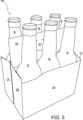
- FIG 1 there is shown a plan view of a blank 10 capable of forming a carton or carrier 90, as shown in Figure 5 , for containing and carrying a group of primary products such as, but not limited to, bottles, hereinafter referred to as articles.
- the blank 10 forms a secondary package of the basket-carrier style for packaging at least one primary product container or package.
- An alternative blank 110 is shown in Figures 7 and 8 for forming an alternative article carrier (not shown).
- the terms “carton” and “carrier” refer, for the nonlimiting purpose of illustrating the various features of the invention, to a container 90 for engaging and carrying articles, such as primary product containers. It is contemplated that the teachings of the invention can be applied to various product containers, which may or may not be tapered and/or cylindrical.
- Other exemplary containers include bottles (for example metallic, glass or plastics bottles), cans (for example aluminium cans), tins, pouches, packets and the like.
- the blanks 10; 110 are formed from a sheet of suitable substrate.
- suitable substrate includes all manner of foldable sheet material such as paperboard, corrugated board, cardboard, plastic, combinations thereof, and the like. It should be recognised that one or other numbers of blanks may be employed, where suitable, for example, to provide the carrier structure described in more detail below.
- the packaging structure or carton 90 described herein may be formed from a sheet material such as paperboard, which may be made of or coated with materials to increase its strength.
- a sheet material such as paperboard
- An example of such a sheet material is tear-resistant NATRALOCK ® paperboard made by WestRock Company.
- the tear resistant materials may be provided by more than one layer, to help improve the tear-resistance of the package.
- one surface of the sheet material may have different characteristics to the other surface.
- the surface of the sheet material that faces outwardly from a finished package may be particularly smooth and may have a coating such as a clay coating or other surface treatment to provide good printability.
- the surface of the sheet material that faces inwardly may, on the other hand, be provided with a coating, a layer, a treatment or be otherwise prepared to provide properties such as one or more of tear-resistance, good glue-ability, heat sealability, or other desired functional properties.
- the blanks 10; 110 are configured to form a carton or carrier 90 for packaging an exemplary arrangement of exemplary articles.
- the blank 10 can be configured to form a carrier for packaging other types, number and size of articles and/or for packaging articles in a different arrangement or configuration for example, but not limited to, fully enclosed cartons or wrap-around carriers, the articles may be cups, pouches, pots or cans.
- FIG. 1 there is illustrated a blank 10 for forming a carton 90 (see Figure 5 ) according to a first embodiment.
- the blank 10 comprises a plurality of panels 12, 14, 16, 18, 20, 22, 24, 26, 28 arranged in a linear series hinged one to the next by fold lines 13, 15, 17, 19, 21, 23, 25, 27 respectively.
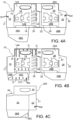
- the blank 10 is foldable into a flat collapsible carrier 90F, as shown in Figure 4C , the flat collapsible carrier 90F is erectable into an article carrier 90 which may be of the basket carrier style.
- the blank 10 comprises a plurality of outer panels 16, 18, 20, 22, 24, 26 for forming a tubular structure.
- the plurality of outer panels 16, 18, 20, 22, 24, 26 comprises a first end panel 16.
- a first side panel 18 is hingedly connected to the first end panel 16 by a hinged connection in the form of a fold line 17.
- a second end panel 20 is hingedly connected to the first side panel 18 by a hinged connection in the form of a fold line 17.
- a third end panel 22 is hingedly connected to the second end panel 20 by a hinged connection in the form of a fold line 21.
- a second side panel 24 is hingedly connected to the third side panel 22 by a hinged connection in the form of a fold line 23 and a fourth end panel 26 is hingedly connected to the second side panel 24 by a hinged connection in the form of a fold line 25.
- the blank 10 comprises a first base panel 38A/38C hinged to the first side panel 18 by a hinged connection in the form of a fold line 37A.
- the blank 10 comprises a second base panel 38B hinged to the second side panel 24 by a hinged connection in the form of a fold line 37B.
- the first and second base panels 38A/38C, 38B are also referred to herein as end closure flaps since they close an end of the tubular structure formed by the plurality of outer panels 16, 18, 20, 22, 24, 26.
- the first base panel 38A/38C comprises a first, proximal, portion 38A hingedly connected to the first side panel 18 by fold line 37A.
- the first base panel 38A/38C comprises a second, distal, portion 38C hingedly connected to the proximal portion 38A by a fold line 37C.
- the first and second base panels 38A/38C, 38B form a base wall or end closure of the tubular structure, the base wall is collapsible into a flat form which is automatically erected to close an end of the tubular structure when the flat collapsed carrier 90F is erected.
- the blank 10 may comprise a medial structure including a first medial panel 14 and a second medial panel 28.
- Medial panels 14, 28 are also referred to herein as intermediate panels.
- the first medial panel 14 is hingedly connected at a first end of the plurality of outer panels 16, 18, 20, 22, 24, 26, to the first end panel 16, by a hinged connection in the form of a fold line 15.
- the second medial panel 28 is hingedly connected at a second, opposing, end of the plurality of outer panels 16, 18, 20, 22, 24, 26, to the fourth end panel 26, by a hinged connection in the form of a fold line 27.
- the first and second medial panels 14, 28 form a divider extending longitudinally between the end walls of the carrier 90.
- the first medial panel 14 provides a first handle panel portion 14A.
- the second medial panel 28 provides a second handle panel portion 28A. Together the first and second medial panels 14, 28 provide a two-ply handle structure, the second ply reinforcing the first ply.
- the first handle panel portion 14A comprises a first handle opening.
- the first handle opening may be defined at least in part by a first handle aperture A2 struck from an upper portion of the first medial panel 14.
- the second handle panel portion 28A comprises a second handle opening.
- the second handle opening may be defined at least in part by a second handle aperture A3 struck from, or defined within, an upper portion of the second medial panel 28.
- the second handle opening is arranged to be disposed in registry or alignment with the first handle opening in a setup condition.
- the blank 10 comprises a securing panel in the form of a medial partition glue flap 12 hingedly connected to an end of the first medial panel 14 (said end opposes an opposing end of the first medial panel 14 to which the first end panel 16 is hingedly connected, defined by fold line 15) by a hinged connection in the form of a fold line 13.
- the fold line 13 may be interrupted by at least one cutaway in the form of an aperture A1, in the illustrated embodiment two apertures A1 interrupt fold line 13 so as to reduce the folding resistance.
- the blank 10 comprises a handle reinforcing structure comprising a first and second handle reinforcing panels 32, 34.
- the first handle reinforcing panel 32 is disposed adjacent to the second end panel 20 and to the first side panel 18. First handle reinforcing panel 32 is separated from second end panel 20 by a first cutline. The first handle reinforcing panel 32 is separated from first side panel 18 by a second cutline, the second cutline is contiguous or continuous with the first cut line.
- the first handle reinforcing panel 32 is hingedly connected to second handle reinforcing panel 34 by a hinged connection in the form of a fold line 33.
- the second handle reinforcing panel 34 is disposed adjacent to the third end panel 22 and to the second side panel 24. Second handle reinforcing panel 34 is separated from third end panel 22 by a third cutline. The second handle reinforcing panel 34 is separated from second side panel 24 by a fourth cutline, the fourth cutline is contiguous or continuous with the third cut line.
- the second handle reinforcing panel 34 is connected to second end panel 20 at a first side edge of the second handle reinforcing panel 34 by a connecting portion in the form of a hinged connection collinearly arranged with fold line 33 and fold line 21.
- the connecting portion 43 is sufficient to maintain the connection between the second handle reinforcing panel 34 and the second end panel 22 during handling of the blank 10 prior to assembly and optionally during at least a portion of the assembly process.
- the handle structure comprises a first bridging panel 30, the first bridging panel 30 is disposed adjacent to the first side panel 18 and is separated therefrom by the second cutline.
- a first side edge of the first bridging panel 30 is coupled to a side edge of the first handle reinforcing panel 32 by a hinged connection in the form of a fold line 31.
- a second side edge of the first bridging panel 30 is coupled to a side edge of the first end panel 16 by a connecting portion in the form of a hinged connection collinearly arranged with fold line 17.
- the connecting portion is sufficient to maintain the connection between the first bridging panel 30 and the first end panel 16 during handling of the blank 10 prior to assembly and optionally during at least a portion of the assembly process.
- the handle structure comprises a second bridging panel 36, the second bridging panel 36 is disposed adjacent to the second side panel 24 and is separated therefrom by the fourth cutline.
- a first side edge of the second bridging panel 36 is coupled to a side edge of the second handle reinforcing panel 34 by a hinged connection in the form of a fold line 35.
- a second side edge of the second bridging panel 36 is coupled to a side edge of the fourth end panel 26 by a connecting portion in the form of a hinged connection collinearly arranged with fold line 27.
- the connecting portion is sufficient to maintain the connection between the second bridging panel 36 and the fourth end panel 26 during handling of the blank 10 prior to assembly and optionally during at least a portion of the assembly process.
- the first handle reinforcing panel 32 comprises a third handle opening.
- the third handle opening may be defined by an optional first cushioning flap 40 struck from the first handle reinforcing panel 32 and hinged thereto by a hinged connection in the form of a fold line 41.
- the first cushioning flap 40 defines at least a part of the third handle opening.
- the second handle reinforcing panel 34 comprises a fourth handle opening.
- the fourth handle opening may be defined by an optional second cushioning flap 42 struck from the second handle reinforcing panel 34 and hinged thereto by a hinged connection in the form of a fold line 43.
- the second cushioning flap 42 defines at least a part of the first handle opening.
- the third and fourth handle openings are arranged to be disposed in registry or alignment with the first and second handle openings in a setup carrier 90.
- the blank 10 may comprise a partition structure P1, P2 which defines or creates a plurality of cells disposed on one or both sides of the divider formed by first and second medial panels 14, 28.
- the blank 10 comprises a first partition structure P1 best illustrated in Figure 2 .
- the first partition structure P1 defines or creates a plurality of cells disposed between the first side panel 18 and the first medial panel 14.
- the first partition structure P1 is defined in a first partition panel portion 14B provided by a lower portion of the first medial panel 14.
- the blank 10 comprises a second partition structure P2.
- the second partition structure P2 defines or creates a plurality of cells disposed between the second side panel 24 and the second medial panel 28.
- the second partition structure P2 is defined in a second partition panel portion 28B provided by a lower portion of the second medial panel 28.
- the first side panel 18 and the second medial panel 28 along with the first and second end panels 16, 20 define a tubular structure or first compartment on a first side of the medial structure or divider.
- the second side panel 24, the second medial panel 28 along with the third and fourth end panels 22, 26 and a portion of the first medial panel 14 define a tubular structure or second compartment on a second side of the medial structure or divider.
- the first compartment provides an interior for receiving at least a lower portion of one or more articles B.
- the second compartment provides an interior for receiving at least a lower portion of one or more articles B.
- the first and second partition structures P1, P2 are substantially similar in construction, albeit the second partition structure P2 is a mirror image (in blank form) of the first partition structure P1. In this way the first and second partition structures P1, P2 are disposed substantially in registry with each other when the blank 10 is folded into a flat collapsed form (see Figure 4C ).
- the first and second partition structures P1, P2 will be described in further detail by reference to the first partition structure P1 as illustrated in Figure 2 .
- the first partition structure P1 comprises a first partition panel 62 struck from, or defined in, the first medial panel 14 and hingedly connected, at a first or proximal end, thereto by a hinged connection in the form of a fold line 63.
- the first partition structure P1 comprises a second partition panel 66 struck from, or defined in, the first medial panel 14 and hingedly connected, at first or a proximal end, thereto by a hinged connection in the form of a fold line 69.
- the first and second partition panels 62, 66 are dimensioned to extend, laterally, between the first medial panel 14 and the first side panel 18 in a set up condition.
- the first partition structure P1 comprises a first glue panel 64 to which the first partition panel 62 is each coupled by a distal end joint.
- the distal end joint takes the form of a fold line 67, the fold line 67 is spaced apart from, inwardly of, an outer or distal end of the first partition panel 62.
- the first glue panel 64 comprises a distal portion 64B hinged to the distal end of the first partition panel 62 by the fold line 67.
- the first glue panel 64 comprises a proximal portion 64A extending from the distal portion 64B and interrupting the fold line 67.
- the proximal portion 64A is struck from a portion of the first partition panel 62 which would otherwise extend laterally between the first medial panel 14 and the first side panel 18 in a set up condition.
- the proximal portion 64A is defined, at least in part, by a cutline 66, cutline 65 is substantially "U” or “C” shaped.
- the cutline 65 extends from the fold line 67 and comprises terminal ends which generally lie on, or intersect, the fold line 67.
- the proximal end of the first partition panel 62 is interrupted by a outline 61, outline 61 is substantially “U” or “C” shaped. Terminal ends of outline 61 may be defined by, or comprise "J" or “C” shaped cuts.
- the cutline 61 defines a tab struck in part from the first partition panel 62 and extending integrally from the first partition panel portion 14B.
- the first partition panel 62 is hingedly connected, at a second or distal end, to the first glue panel 64 by a hinged connection in the form of the fold line 67.
- Fold line 67 defines an outer end of the first partition panel 62
- fold line 63 defines an inner end of the first partition panel 62 a linear dimension L1 is defined therebetween.
- the first partition panel 62 and the first glue panel 64 are defined by a cutline 73 defined in the first partition panel portion 14B.
- the cutline 73 interrupts, or intersects, the hinged connection, fold line 69, hinging the second partition panel 66 to the first partition panel portion 14B.
- the distal portion 64B of the first glue panel 64 is struck from material which would otherwise form the second partition panel 66.
- the fold line 67 may be collinear with the fold line 69.
- the second partition panel 66 is hingedly connected to a second glue panel 68 by a hinged connection in the form of fold line 83.
- the second partition panel 68 comprises an outer end, defined by a portion of cutline 75, said portion may be collinear, coincident or coextensive with the fold line 15 between the first medial panel 14 and the first end panel 16.
- Fold line 83 is offset, inset from, the outer end of the second partition panel 66.
- the second glue panel 68 is struck from, or defined in, material which would otherwise form a portion of the first partition panel 62 which would extend laterally between the first medial panel 14 and the first side panel 18 in a set up condition.
- the second partition panel 66 comprises a distal portion 66B, the distal portion 66B is hingedly connected to a main body of the second partition panel 66 by a hinged connection in the form of a fold line 77.
- the distal portion 66B forms a joint portion coupling the second glue panel 68 to the second partition panel 66.
- Fold line 77 is offset, inset from, the outer or free end E1 of the second partition panel 66 defined by a portion of cutline 75. Fold line 77 may be collinear with the fold line 83.
- the distal portion 66B of the second partition panel 66 comprises a weakened line 79 spaced apart from fold lines 77, 83 and parallel thereto.
- the weakened line 79 is offset, inset from, the outer or free end E1 of the second partition panel 66 defined by the outermost portion of cutline 75.
- the weakened line 79 may be formed from one or more elements and may comprise a perforation, at least one cut or half cut, at least one opening, aperture, slot or slit, or may comprises at least one crease line or any combination of these features.
- the second glue panel 68 is defined, at least in part, by a cutline 71, cutline 71 is substantially "U" or "C” shaped.
- the cutline 71 extends from the fold line 77 and comprises terminal ends, disposed proximate or adjacent to the free end E1 of the second partition panel 66, which terminal ends generally lie on, or intersect, a notional line N1 that is collinear, coincident or coextensive with the fold line 77.
- the notional line N1 is spaced apart from and parallel to the fold line 69 hinging the second partition panel 66 to the first medial panel 14.
- the notional line N1 is spaced apart from the free end E1 of the second partition panel 66 by greater distance than the weakened line 79.
- the second glue panel 68 comprises a bridging or connection portion 68B defined in part by fold line 83 and a second fold line 81 spaced apart and parallel thereto.
- the connection portion 68B couples a securing portion or main body of the second glue panel 68 to the distal portion 66B of the second partition panel 66.
- the first medial panel 14 may comprise a raised or embossed region EB raises a surface of the first medial panel 14 such a that a secure bond between the first medial panel 14 and the second handle reinforcing panel 34, with which it is disposed in face-to-face relationship with, can be formed.
- the first medial panel 14 may comprise one or more embossed or crease lines EL, the embossed lines EL may increase the rigidity of the region of the first medial panel 14 in which the are formed, said region may be define a portion of the medial structure or divider which is single ply in construction.
- the second medial panel 28 may be shorter in width than the first medial panel 14.
- the first medial panel 14 extends fully between opposed end walls of the carrier 90.
- the second medial panel 28 extends only a portion of the way between opposed end walls of the carrier 90. This arrangement avoids requiring the second medial panel 28 to be disposed in an overlapping or overlying relationship with the securing panel 12 during construction of the carrier 90, best shown in Figure 4A . This limits the flat collapsed carrier 90F to having a four ply or four layer structure or arrangement and avoids creating a five play or layer section in the region of the securing flap 12.
- Fold line 69 defines an inner end of the second partition panel 66.
- the fold line 77 and the fold line 69 define a second linear dimension L2 therebetween.
- the second linear dimension L2 is less than the first linear dimension L1.
- the first linear dimension L1 is substantially equal to the distance between the first medial panel 14 and the first side panel 18.
- the second linear dimension L2 is less than the distance between the first medial panel 14 and the first side panel 18.
- the fold line 69 and the outer or free end E1 of the partition panel 66 define a third linear dimension L3 therebetween.
- the third linear dimension L3 is greater than second linear dimension L2 and may be equal or greater than first linear dimension L1.
- the connecting portion 68B allows the gap between the fold line 83 and the first side panel 18 to be bridged when the carrier 90 is in a set up condition, best illustrated in Figure 6 .
- the blank 10 is foldable to form a package 90 as illustrated in Figure 5 .
- the carton 90 can be formed by a series of sequential folding operations in a straight-line machine so that the carton 90 is not required to be rotated or inverted to complete its construction.
- the folding process is not limited to that described below and may be altered according to particular manufacturing requirements.
- Glue or other adhesive treatment is applied to the third end panel 22 proximate the fold line 21.
- glue or other adhesive treatment may be applied to the medial partition glue flap 12.
- Glue or other adhesive treatment is applied to the first glue panel 64 and to the second glue panel 68 of the first partition structure P1, the connection portion 68B is glue free.
- glue or other adhesive treatment may be applied to corresponding regions of the first side panel 18 as shown in Figure 3 .
- Glue or other adhesive treatment is applied to the first bridging panel 30.
- glue or other adhesive treatment may be applied to a corresponding region of the first end panel 16.
- Glue or other adhesive treatment is applied to the first handle reinforcing panel 32.
- glue or other adhesive treatment may be applied to a corresponding region of the first handle panel portion 14A.
- the first medial panel 14 and the first end panel 16 are folded, with respect to the first side panel 18 about fold line 17, as indicated by direction arrow D1 shown in Figure 4A .
- the first medial panel 14 is brought into face contacting relationship with a portion of the first side panel 18 and the second end panel 20, the first end panel 16 is brought into face contacting relationship with a portion of the first side panel 18.
- the medial partition glue flap 12 is secured to the third end panel 22 in face contacting relationship therewith.
- the first and second glue panels 66, 68 of the first partition structure P1 are secured to the first side panel 18.
- the first bridging panel 30 is secured to the first end panel 16.
- the first handle reinforcing panel 32 is secured to the first handle panel portion 14A.
- Glue or other adhesive treatment is applied to the pair of glue panels of the second partition structure P2, the connecting portion is glue free.
- glue or other adhesive treatment may be applied to a corresponding region of the second side panel 24, as shown in Figure 3 .
- Glue or other adhesive treatment is applied to the second bridging panel 36.
- glue or other adhesive treatment may be applied to a corresponding region of the fourth end panel 26.
- Glue or other adhesive treatment is applied to the second handle reinforcing panel 34.
- glue or other adhesive treatment may be applied to a corresponding region of the second handle panel portion 28A.
- the second medial panel 28 and the fourth end panel 26 are folded, with respect to the second side panel 24 about fold line 25, as indicated by direction arrow D2 shown in Figure 4A .
- the second medial panel 28 is brought into face contacting relationship with a portion of the second side panel 24 and the third end panel 22, the fourth end panel 26 is brought into face contacting relationship with a portion of the second side panel 24.
- the glue panels of the second partition structure P2 are secured to the second side panel 24.
- the second bridging panel 36 is secured to the fourth end panel 26.
- the second handle reinforcing panel 34 is secured to the second handle panel portion 28A.
- Glue or other adhesive treatment is applied to the first medial panel 14, the first and second partition panels 62, 66 and the first and second glue panels 64, 68 are glue free, as shown in Figure 4B .
- glue or other adhesive treatment may be applied to corresponding regions of the second medial panel 28.
- Glue is applied to the embossed or raised are EB or to a corresponding region of the second handle reinforcing panel 34.
- the distal portion 38C of the first base panel 38A/38C is folded, about fold line 37C into face-to-face relationship with the proximal portion 37A, as indicated by direction arrow D3 in Figure 4B .
- Glue or other adhesive treatment is applied to the distal portion 38C of the first base panel 38A/38C, alternatively glue may be applied to the second base panel 38B.
- the third end panel 22, together with the second side panel 24, the second medial panel 28 and the fourth end panel 26, are folded about the fold line 21 to bring the second medial panel 28 into face-to-face relationship with the first medial panel 14 as indicated by direction arrow D4 in Figure 4C .
- the first medial panel 14 is secured to the second medial panel 28. In this way a flat collapsed tubular structure is formed.
- a flat collapsed carrier 90F is thereby formed, as shown in Figure 4C , the flat collapsed carrier 90F can be readily shipped or distributed in the flat condition to a plant for erecting and loading with primary product containers.
- the flat collapsed carrier 90F can be opened into a basket-style article carrier by separating the first and second side panels 18, 24 to form a tubular structure defined by the outer panels 16, 18, 20, 22, 24, 26.
- the outer panels 16, 18, 20, 22, 24, 26 define an interior chamber.
- the partition structures P1, P2 are automatically erected when the flat collapsed carrier 90F is opened out or erected into the tubular form.
- the first and second medial panels 14, 28 form a partition or divider, that is disposed medially within the interior of the carrier 90 formed by the outer panels 16, 18, 20, 22, 24, 26.
- the partition divides the interior of the carrier 90 into two separate compartments on opposing sides of the first and second medial panels 14, 28.
- the first partition structure P1 is automatically erected to form a first plurality of cells in a first compartment disposed on a first side of the first and second medial panels 14, 28.
- the second partition structure P2 is automatically erected to form a second plurality of cells in a second compartment disposed on a second side of the first and second medial panels 14, 28.
- a base wall 38A/38C/38B is automatically erected to close a first or lower end of the tubular structure.
- the carrier 90 may be loaded with a group of articles; in the embodiment illustrated in Figure 5 six articles B are arranged in a 3 ⁇ 2 array.
- the group of articles may be loaded through the upper end of the tubular structure formed by the outer panels 16, 18, 20, 22, 24, 26.
- Figure 7 shows a blank 110 for forming a carton or carrier (not shown) according to a second embodiment.
- the blank 110 forms a flat collapsible carrier of a parallelogram style, that is to say the end walls do not fold about themselves as those of the embodiment of Figures 1 to 6 , and described above, do.
- the outer panels 112, 114, 116, 118 define a parallelogram in the flat collapsed state.
- the flat collapsed carrier 90F shown in Figure 4C is sometimes referred to as an "arrowhead" style due to the shape the outer panels 16, 18, 20, 22, 24, 26 adopt in the collapsed state.
- the blank 110 comprises a plurality of panels 112, 114, 116, 118, 120, 122,126 arranged in a linear series hinged one to the next by fold lines 13, 15, 17, 19, 21, 25 respectively.
- the blank 110 comprises a plurality of outer panels 112, 114, 116, 118for forming a tubular structure.
- the plurality of outer panels 112, 114, 116, 118 comprises a first end panel 112.
- a first side panel 114 is hingedly connected to the first end panel 112 by a hinged connection in the form of a fold line 113.
- a second end panel 116 is hingedly connected to the first side panel 114 by a hinged connection in the form of a fold line 115.
- a second side panel 118 is hingedly connected to the second side panel 116 by a hinged connection in the form of a fold line 117 and a first inner end panel 120 is hingedly connected to the second side panel 118 by a hinged connection in the form of a fold line 119.
- the blank 110 comprises a first base panel 138A hinged to the first side panel 114 by a hinged connection in the form of a fold line 137A.
- the blank 110 comprises a second base panel 138B hinged to the second side panel 124 by a hinged connection in the form of a fold line 137B.
- the first and second base panels 138A, 138B are also referred to herein as end closure flaps since they close an end of the tubular structure formed by the plurality of outer panels 112, 114, 116, 118.
- the first and second base panels 138A, 138B are engageable with one another in an overlapping relationship to form a composite base wall 138A/138B of a carrier.
- the blank 110 may comprise a complementary locking mechanism (also referred to as a press-activated locking feature) for securing the first base panel 138A to the second base panel 138B.
- the first base panel 138A may comprise at least one first part M of the complementary locking mechanism.
- the second base panel 138B may comprise at least one second part F of the complementary locking mechanism.
- the first base panel 138A comprises four male tabs M struck therefrom so as to be defined within the first base panel 138A. Each of the male tabs M is hingedly connected to the first base panel 138A by a hinged connection in the form of a fold line.
- the second part F of the complementary locking mechanism forms a receiver.
- the receiver comprises an opening or slot for receiving the male tab M.
- the second base panel 138B comprises four optional female tabs each defining an opening or slot in the second base panel 138B; the female tabs forming at least part of the receiver.
- the openings in the second base panel 138B are configured to receive respective ones of the male tabs M.
- the female tabs F are arranged to be displaced out of the second base panel 138B to form said openings and to bear against the respective male tab M when received therein.
- the complementary locking mechanism M/F may be omitted, the first and second base panels 138A, 138B may be secured to each other by other means, such as but not limited to adhesive or staples.
- first and second base panels 138A, 138B may comprise at least one first aperture A1.
- first base panel 138A comprises three first apertures A1 and the second base panel 138B comprises three first apertures A1.
- the first apertures A1 may be employed to facilitate construction of the carrier 90.
- a packaging machine component or tool may engage with the first apertures A1 to facilitate alignment of the first and second base panels 138A, 138B with respect to each other or to align the first part M of the complementary locking mechanism with the second part F of the complementary locking mechanism.
- the complementary locking mechanism illustrated and described is entirely optional.
- the blank 110 may comprise a medial structure including a first medial panel 122 and a second medial panel 124.
- Medial panels 122, 124 are also referred to herein as intermediate panels.
- the first medial panel 122 is hingedly connected, along a first side edge, to the first inner end panel 120 by a hinged connection in the form of a fold line 121.
- a securing flap 126 is hingedly connected to the first medial panel 122, along a second, opposing, side edge, by a hinged connection in the form of a fold line 125.
- the second medial panel 124 is hingedly connected, along an end or lower edge, to an end or lower edge of the first medial panel 122 by a hinged connection in the form of a fold line 123.
- the first medial panel 122 provides a first handle panel portion 122A.
- the second medial panel 124 provides a second handle panel portion 124A. Together the first and second medial panels 122, 124 provide a two-ply handle structure, the second ply reinforcing the first ply.
- the first handle panel portion 122A comprises a first handle opening.
- the first handle opening may be defined at least in part by a first handle aperture A3 struck from an upper portion of the first medial panel 122.
- the first handle opening may be defined in part by a handle flap 180 struck from or defined in the first handle panel portion 122A and hingedly connected thereto by a hinged connection in the form of a fold line 181.
- the second handle panel portion 124A comprises a second handle opening.
- the second handle opening may be defined at least in part by a second handle aperture A2 struck from, or defined within, an upper portion of the second medial panel 124.
- the second handle opening is arranged to be disposed in registry or alignment with the first handle opening in a setup condition.
- the blank 110 may comprise a handle panel 128 hingedly connected to the first handle panel portion 122A by a hinged connection in the form of a fold line 127.
- Fold line 127 may be collinear with fold line 121.
- the handle panel 128 is disposed alongside the first inner end panel 120 and the second side panel 118 and is separated therefrom by a first cut line or weakened line of severance.
- the blank 110 comprises a first bridging panel 130, the first bridging panel 130 is disposed adjacent to the second side panel 118 and is separated therefrom by a second cutline the second cutline being contiguous or continuous with the first cut line.
- a first side edge of the first bridging panel 130 is coupled to a side edge of the handle panel 128 by a hinged connection in the form of a fold line 129.
- a second side edge of the first bridging panel 130 is coupled to a side edge of the second end panel 116 by a connecting portion in the form of a hinged connection collinearly arranged with fold line 117.
- the connecting portion is sufficient to maintain the connection between the first bridging panel 130 and the second end panel 116 during handling of the blank 110 prior to assembly and optionally during at least a portion of the assembly process.
- the handle panel 128 comprises a third handle opening.
- the third handle opening may be defined at least in part by a handle aperture A3 struck from the handle panel 128.
- the third handle opening may be defined in part by a handle flap 180 struck from or defined in the handle panel 128 and hingedly connected thereto by a hinged connection in the form of a fold line 181.
- the third handle opening is arranged to be disposed in registry or alignment with the first and second handle openings in a setup condition.
- the blank 110 comprises a partition structure P1, P2 which defines or creates a plurality of cells disposed on one or both sides of the divider formed by first and second medial panels 122, 124.
- the blank 110 comprises a first partition structure P1 best illustrated in Figure 8 .
- the first partition structure P1 defines or creates a plurality of cells disposed between the first side panel 114 and the first medial panel 122.
- the first partition structure P1 is defined in a first partition panel portion 122B provided by a lower portion of the first medial panel 122.
- the blank 110 comprises a second partition structure P2.
- the second partition structure P2 defines or creates a plurality of cells disposed between the second side panel 118 and the second medial panel 124.
- the second partition structure P2 is defined in a second partition panel portion 124B provided by a lower portion of the second medial panel 124.
- the second side panel 118, the second medial panel 124 along with the portions of the first and second end panels 112, 116 define a tubular structure or second compartment on a second side of the medial structure or divider.
- the first compartment provides an interior for receiving at least a lower portion of one or more articles.
- the second compartment provides an interior for receiving at least a lower portion of one or more articles.
- the first partition structure P1 comprises a first partition panel 160 struck from, or defined in, the first medial panel 122 and hingedly connected, at a first or proximal end, thereto by a hinged connection in the form of a fold line 161.
- the first partition structure P1 comprises a second partition panel 164 struck from, or defined in, the first medial panel 122 and hingedly connected, at first or a proximal end, thereto by a hinged connection in the form of a fold line 165.
- the first and second partition panels 160, 164 are dimensioned to extend, laterally, between the first medial panel 122 and the first side panel 114 in a set up condition.
- the first partition structure P1 comprises a first glue panel 162 to which the first and second partition panels 160, 164 are each coupled by distal end joints.
- the second partition panel 164 is hingedly connected, at a second or distal end, to a second end of the first glue panel 162 by a hinged connection in the form of fold line 163.
- Fold line 163 defines an outer end of the second partition panel 164
- fold line 165 defines an inner end of the second partition panel 164 a linear dimension is defined therebetween.
- the first partition panel 160 is hingedly connected to a first end of the first glue panel 162 by a joint portion JP.
- the first partition panel 160 is disposed alongside the first glue panel 162, and is separated therefrom by a cutline 169.
- the cutline 169 terminates with a "C" shaped cut 169E, the cut 169E is bisected by the cut line 169, such that a cut 169E extends into each of the first partition panel 160 and the first glue panel 162.
- the joint portion JP is defined, at least in part, between the cut 169E and a cutline 169B defining a free end edge of each of the first partition panel 160 and the first glue panel 162.
- the joint portion JP may comprise a weakened line 167 spaced apart from fold lines 161, 163 and parallel thereto.
- the weakened line 167 is offset, inset from, the outer or free end of the first partition panel 160 and the free end of the first glue panel 162 defined by the cutline 169B.
- the weakened line 167 may be formed from one or more elements and may comprise a perforation, at least one cut or half cut, at least one opening, aperture, slot or slit, or may comprises at least one crease line or any combination of these features.
- the weakened line 167 is disposed between the cut 169E and the free ends of the first partition panel 160 and the free end of the first glue panel 162.
- the second partition structure P2 comprises a third partition panel 170 struck from, or defined in, the second medial panel 124 and hingedly connected, at a first or proximal end, thereto by a hinged connection in the form of a fold line 171.
- the second partition structure P2 comprises a fourth partition panel 174 struck from, or defined in, the second medial panel 124 and hingedly connected, at first or a proximal end, thereto by a hinged connection in the form of a fold line 175.
- the third and fourth partition panels 170, 174 are dimensioned to extend, laterally, between the second medial panel 124 and the second side panel 118 in a set up condition.
- the second partition structure P2 comprises a second glue panel 172 to which the third and fourth partition panels 170, 174 are each coupled by distal end joints.
- the third partition panel 170 is hingedly connected, at a second or distal end, to a first end of the second glue panel 172 by a hinged connection in the form of fold line 173.
- Fold line 173 defines an outer end of the third partition panel 170
- fold line 171 defines an inner end of the third partition panel 170 a linear dimension is defined therebetween.
- Fold line 173 may be collinear with fold line 175.
- the fourth partition panel 174 is hingedly connected to a second end of the second glue panel 172 by a hinged connection in the form of fold line 177.
- the fourth partition panel 174 is struck from material which would otherwise form the second glue panel 172.
- the fourth partition panel 174 defined, at least in part by, and is separated from the second glue panel 172, by a pair of cutlines 179A, 179B. Each of the pair of cutlines 179A, 179B extends between fold line 175 and fold line 177.
- a portion 172B of the second glue panel 172 is provided by material outside of the footprint of the second medial panel 124, unlike the first partition structure P1 where the entire first partition structure P1 is provided from material within the footprint of the first medial panel 122.
- the carton can be formed by a series of sequential folding operations in a straight-line machine so that the carton is not required to be rotated or inverted to complete its construction.
- the folding process is not limited to that described below and may be altered according to particular manufacturing requirements.
- Glue or other adhesive treatment is applied to the first medial panel 122.
- glue or other adhesive treatment may be applied to the second medial panel 124.
- the second medial panel 124 is folded with respect to the first medial panel 122 about fold line 123 and disposed face to face relationship therewith.
- the second medial panel 124 is secured to the first medial panel 122.
- Glue or other adhesive treatment is applied to the handle panel 128.
- glue or other adhesive treatment may be applied to the second handle panel portion 124A.
- Glue or other adhesive treatment GA is applied to the second glue panel 172.
- glue or other adhesive treatment may be applied to a corresponding region of the second side panel 118.
- the first medial panel 122 along with the second medial panel 124, is folded about fold line 121 to bring the second medial panel 124 into face-to-face relationship with the second side panel 1118 and the first inner end panel 120.
- the handle panel 128 is secured to the second handle panel portion 124A.
- the second glue panel 172 is secured to the second side panel 118.
- Glue or other adhesive treatment is applied to the securing flap 126.
- glue or other adhesive treatment may be applied to the second end panel 116.
- Glue or other adhesive treatment GA is applied to the first glue panel 162.
- glue or other adhesive treatment may be applied to a corresponding region of the first side panel 114.
- the second side panel 118 along with the first and second medial panels 122, 124 and the first inner end panel 120, is folded with respect to the second end panel 116, about fold line 117, to bring the securing flap 126 into face-to-face relationship with the second end panel 116 and the first medial panel 124 into face-to-face relationship with a portion of the first side panel 114.
- the securing flap 126 is secured to the second end panel 116.
- the first glue panel 162 is secured to the first side panel 114.
- Glue or other adhesive treatment is applied to the first inner end panel 120.
- glue or other adhesive treatment may be applied to a corresponding region of the first end panel 112.
- the first end panel 112 is folded with respect to the first side panel 114, about fold line 113, to bring the first end panel 112 into face contacting relationship with the first inner end panel 120.
- the first end panel 112 is secured to the first inner end panel 120.
- the flat collapsed carrier can be erected to form a tubular structure having an interior for receiving articles, the interior is divided into cells by the medial panels 122, 124 and the partition panels 160, 164, 170, 174, the cell structure is automatically erected when the flat collapsed carrier is erected into the tubular structure.
- the carrier can be top or bottom loaded, that is to say articles can be inserted into an open top or bottom end of the tubular structure.
- a base wall can be formed after loading the articles by folding the base panels 138A, 138B with respect to the respective one of the first and second side panels 114, 118 to which they are hinged.
- the base wall is formed before loading with articles, in such embodiments the carrier is loaded through an open top end thereof.
- the present disclosure provides an article carrier 90 comprising a plurality of primary panels 16, 18, 20, 22, 24, 26 forming a tubular structure defining an interior of the article carrier 90.
- the plurality of primary panels includes: a first panel 14, 28; and a second panel 18, 24 opposing the first panel 14, 28.
- the carrier 90 further comprises a partition structure P1, P2 dividing the interior into two or more article-receiving cells.
- the present disclosure provides a carton 90 comprising first and second panels 14/18, 28/24; 122/114, 124/118, spaced apart from each other and disposed in opposition.
- the first and second opposing panels 14/18, 28/24; 122/114, 124/118 define, in part, a chamber therebetween.
- the illustrated embodiment provides two chambers disposed back-to-back, in alternative embodiments only one chamber may be provided.
- the carton 90 comprises a partition structure P1, P2 extending between the first and second panels 14/18, 28/24; 122/114, 124/118.
- the partition structure P1, P2 comprises a partition panel 66; 160 formed at least in part from the first panel 14, 28; 122 and hingedly connected to the first panel 14, 28; 122 by a first fold line 69, 161 and a securing panel 68; 162 formed from one of the first panel 14, 28; 122 and the partition panel 66; 160 and foldably connected to the partition panel 66; 160 by a joint portion 66B, JP.
- the securing panel 68; 162 is defined at least in part by a cut line 71; 169 having a terminal end T e proximate to a free end E1 of the partition panel 66; 160.
- the cut line 71; 169 defines a notional line N1 parallel to the first fold line 69, 161 and passing through the terminal end T e of the cut line 71; 169.
- the joint portion 66B, JP comprises a weakened line 79, 167 spaced apart from the notional line N1.
- the weakened line 79, 167 may facilitate erection of the flat collapsed carrier 90F into an erected carrier 90 in particular in automated packaging machines. It may reduce the likelihood of the partition panel 66; 160, in particular the free end E1 snagging, catching or otherwise inhibiting movement of the carrier panels during erection or when folding the carrier 90 into a flat collapsed form 90F from the erected condition.
- the weakened line 79, 167 may allow an end of the partition panel 66; 160 to readily deform to allow the partition panel 66; 160 and second or side panel 18, 24; 114, 118 to pass by each other.
- the end of the partition panel 66; 160 may, due to inherent resilience of the material substrate from which the carrier 90 is formed, return to a substantially planar arrangement with the remainder of the partition panel 66; 160.
- the erected article carrier 90 is less likely to return to a flat collapsed state, the tendency of the article carrier 90 is to return to a flat collapsed state is reduced, and the article carrier 90 may also have greater robustness or integrity.
- the joint portion 66B, JP comprises an area of the partition structure P1, P2 extending between the notional line N1 and the free end E1 of the partition panel 66; 160 and wherein the weakened line 79, 167 is spaced apart from the free end E1.
- the weakened line 79, 167 may be disposed or arranged parallel to the notional line N1.
- the weakened line 79, 167 may be formed from one or more elements selected from the group consisting of a perforation, at least one cut, at least one half-cut, at least one opening, at least one crease line.
- the free end E1 of the partition panel 66; 160 may lie upon a hinged connection between first panel 14, 28; 122 and a third panel 16, 26; 120 hingedly connected to the first panel 14, 28; 122.
- the partition structure P1, P2 may comprise a second partition panel 62 formed at least in part from the first panel 14, 28 and hingedly connected to the first panel 14, 28 at a first proximal end by a second fold line 63, a second securing panel 65 is hingedly connected to a second distal end by a hinged connection in the form of a third fold line 67.
- the third fold line 67 is spaced apart from the second fold line by a first distance L1.
- the first distance L1 is equal to the distance between first and second panels 14/18, 28/24.
- the second securing panel 62 is defined at least in part by a cut line 65 having at least one terminal end lying on the third fold line 67.
- the first fold line 69, 161 is spaced apart from the notional line N1 by a second distance L2, second distance L2 is less than the first distance L1.
- a portion 64B of the second securing panel 64 may be struck from, or formed from, a part of the partition panel 66.
- the size and shape of the panels and apertures may be adjusted to accommodate articles of differing size or shape.
- the present invention is not limited to cartons of the basket carrier style, the invention may be employed with other carton styles such as, but not limited to, open top crates, lidded or closed top crates and fully enclosed cartons.
- the medial panel may omitted
- the partition structure may be formed from a first one of a pair of opposing wall panels, the opposing wall panels defining in part an interior of the carrier.
- the partition structure may divide the interior into two or more article receiving cells.
- the partition structure may comprise a lateral partition panel hingedly connected at a proximal end to said first one of the pair of opposing wall panels by proximal end fold line and at its distal end to a glue panel by a distal end joint, the glue panel being secured to the second one of the pair of opposing wall panels.
- hinged connection and “fold line” refer to all manner of lines that define hinge features of the blank, facilitate folding portions of the blank with respect to one another, or otherwise indicate optimal panel folding locations for the blank. Any reference to “hinged connection” should not be construed as necessarily referring to a single fold line only; indeed, a hinged connection can be formed from two or more fold lines wherein each of the two or more fold lines may be either straight/linear or curved/curvilinear in shape. When linear fold lines form a hinged connection, they may be disposed parallel with each other or be slightly angled with respect to each other.
- curvilinear fold lines When curvilinear fold lines form a hinged connection, they may intersect each other to define a shaped panel within the area surrounded by the curvilinear fold lines.
- a typical example of such a hinged connection may comprise a pair of arched or arcuate fold lines intersecting at two points such that they define an elliptical panel therebetween.
- a hinged connection may be formed from one or more linear fold lines and one or more curvilinear fold lines.
- a typical example of such a hinged connection may comprise a combination of a linear fold line and an arched or arcuate fold line which intersect at two points such that they define a half-moon shaped panel therebetween.
- fold line may refer to one of the following: a scored line, an embossed line, a debossed line, a line of perforations, a line of short slits, a line of half-cuts, a single half-cut, an interrupted cutline, a line of aligned slits, a line of scores and any combination of the aforesaid options.
- hinged connections and fold lines can each include elements that are formed in the substrate of the blank including perforations, a line of perforations, a line of short slits, a line of half-cuts, a single half-cut, a cutline, an interrupted cutline, slits, scores, any combination thereof, and the like.
- the elements can be dimensioned and arranged to provide the desired functionality.
- a line of perforations can be dimensioned or designed with degrees of weakness to define a fold line or a severance line or both.
- the line of perforations can be designed to facilitate folding and resist breaking, to facilitate folding and facilitate breaking with more effort, or to facilitate breaking with little effort.
- in registry with refers to the alignment of two or more elements in an erected carton, such as an aperture formed in a first of two overlapping panels and a second aperture formed in a second of two overlapping panels. Those elements in registry with each other may be aligned with each other in the direction of the thickness of the overlapping panels. For example, when an aperture in a first panel is "in registry with" a second aperture in a second panel that is placed in an overlapping arrangement with the first panel, an edge of the aperture may extend along at least a portion of an edge of the second aperture and may be aligned, in the direction of the thickness of the first and second panels, with the second aperture.
Landscapes
- Engineering & Computer Science (AREA)
- Mechanical Engineering (AREA)
- Cartons (AREA)
Abstract
Description
- The present invention relates to carriers and to blanks for forming the same. More specifically, but not exclusively, the invention relates to a carrier having a partition structure feature defining cells or compartments within an interior of a carrier of the basket-style.
- In the field of packaging, it is known to provide article carriers or cartons for carrying multiple articles. Cartons are well known in the art and are useful for enabling consumers to transport, store and access a group of articles for consumption. For cost and environmental considerations, such cartons or carriers need to be formed from as little material as possible and cause as little wastage in the materials from which they are formed as possible. Further considerations are the strength of the carton and its suitability for holding and transporting large weights of articles. It is desirable that the contents of the carton are secure within the carton.
- It is an object of the present invention to provide to a carrier having a partition structure for separating articles within an interior chamber of the carrier. It is desirable to minimise or reduce the material required to produce the carrier for economic or environmental benefit or both.
- It is desirable that the blank from which the carrier is formed can be readily assembled into a carrier in a simple and efficient manner.
- The present invention seeks to provide an improvement in the field of cartons, typically formed from paperboard or the like.
- A first aspect of the invention provides an article carrier for packaging one or more articles. The article carrier comprises a plurality of primary panels for forming a tubular structure. The plurality of primary panels includes a first panel and a second panel. The first and second panels are spaced apart from, and disposed in opposition to, each other. The article carrier further comprises a partition structure extending between the first and second panels. The partition structure comprises a first partition panel and a first securing panel. The first partition panel is formed at least in part from the first panel and is hingedly connected to the first panel by a first fold line. The first securing panel is formed from one of the first panel and the first partition panel and is foldably connected to the first partition panel by a joint portion of the first partition panel. The first securing panel is defined, at least in part, by a cut line when the article carrier is in a blank form. The cut line has a terminal end proximate to a free end of the first partition panel. The cut line defines a notional line passing through the terminal end of the cut line. The notional line is parallel to the first fold line. The joint portion comprises a weakened line spaced apart from the notional line. Optionally, the joint portion comprises an area of the partition panel extending between the notional line and the free end of the partition panel and wherein the weakened line is spaced apart from the free end.
- Optionally, the weakened line is disposed or arranged parallel to the notional line.
- Optionally, the weakened line is formed from one or more elements selected from the group consisting of a perforation, at least one cut, at least one half-cut, at least one opening, at least one crease line.
- Optionally, the free end of the partition panel lies upon a first hinged connection between the first panel and a third panel.
- Optionally, the partition structure comprises a second partition panel and a second securing panel. The second partition panel may be formed at least in part from the first panel and hingedly connected to the first panel by a second fold line. The second securing panel may be hingedly connected to the second partition panel by a third fold line.
- Optionally, the third fold line is spaced apart from the second fold line by a first distance. The first distance L1 may be substantially equal to the distance between the first and second panels.
- Optionally, the second securing panel is defined at least in part by a cut line when the carrier is in a blank form. The cut line may have at least one terminal end lying on the third fold line. The first fold line may be spaced apart from the notional line by a second distance. The second distance may be less than the first distance.
- Optionally, a portion of the second securing panel is struck from the partition panel.
- Optionally, the notional line is spaced apart from the first fold line by a distance which is less than a distance between the first and second panels. A second aspect of the invention provides a blank for forming an article carrier. The blank comprises a plurality of primary panels for forming walls of a tubular structure. The plurality of primary panels includes a first panel and a second panel. The first and second panels are configured to be spaced apart from, and disposed in opposition to, each other in a set-up carrier. The blank further comprises a plurality of secondary panels for forming a partition structure configured to extend between the first and second panels in a set-up carrier. The plurality of secondary panels comprises a first partition panel and a first securing panel. The first partition panel is formed at least in part from the first panel and hingedly connected to the first panel by a first fold line. The first securing panel is formed from one of the first panel and the first partition panel. The first securing panel is foldably connected to the first partition panel by a joint portion of the first partition panel. The first securing panel is defined, at least in part, by a cut line having a terminal end proximate to a free end of the first partition panel. The cut line defines a notional line passing through the terminal end of the cut line. The notional line is parallel to the first fold line. The joint portion comprises a weakened line spaced apart from the notional line.
- Optionally, the joint portion comprises an area of the first partition panel extending between the notional line and the free end of the first partition panel. The weakened line may be spaced apart from the free end of the first partition panel.
- Optionally, the weakened line is disposed parallel to the notional line.
- Optionally, the weakened line is formed from one or more elements selected from the group consisting of a perforation, at least one cut, at least one half-cut, at least one opening, at least one crease line.
- Optionally, the free end of the first partition panel lies upon a first hinged connection between the first panel and a third panel of the plurality of primary panels.
- Optionally, the plurality of secondary panels further comprise a second partition panel and a second securing panel. The second partition panel may be formed at least in part from the first panel and hingedly connected to the first panel by a second fold line. The second securing panel may be hingedly connected to the second partition panel by a third fold line.
- Optionally, the third fold line is spaced apart from the second fold line by a first distance. The first distance may be substantially equal to a distance between the first and second panels in a set-up condition.
- Optionally, the second securing panel is defined at least in part by a cut line having at least one terminal end lying on the third fold line. The first fold line may be spaced apart from the notional line by a second distance. The second distance may be less than the first distance.
- Optionally, a portion of the second securing panel is formed from the first partition panel.
- Optionally, the third panel is hingedly connected to the second panel by a second hinged connection which is spaced apart from the first hinged connection by a first distance wherein the notional line is spaced apart from the first fold line by a second distance. The second distance may be less than the first distance.
- Further features and advantages of the present invention will be apparent from the specific embodiments illustrated in the drawings and discussed below.
- Within the scope of this application, it is envisaged or intended that the various aspects, embodiments, examples, features and alternatives set out in the preceding paragraphs, in the claims and/or in the following description and drawings may be considered or taken independently or in any combination thereof.
- Features or elements described in connection with, or relation to, one embodiment are applicable to all embodiments unless there is an incompatibility of features. One or more features or elements from one embodiment may be incorporated into, or combined with, any of the other embodiments disclosed herein, said features or elements extracted from said one embodiment may be included in addition to, or in replacement of one or more features or elements of said other embodiment.
- A feature, or combination of features, of an embodiment disclosed herein may be extracted in isolation from other features of that embodiment. Alternatively, a feature, or combination of features, of an embodiment may be omitted from that embodiment.
- Embodiments of the invention will now be described with reference to the accompanying drawings, in which:
-
Figure 1 is a plan view from above of a blank for forming a carrier according to a first embodiment; -
Figure 2 is an enlarged view of a portion of the blank ofFigure 1 ; -
Figure 3 illustrates a stage of construction of the blank ofFigure 1 into a flat collapsed carrier; -
Figures 4A, 4B and 4C illustrate further stages of construction of the blank ofFigure 1 into a flat collapsed carrier; -
Figure 5 is a perspective view from above of a carton formed from the blank ofFigure 1 ; -
Figure 6 is a perspective view of an interior of a carton formed from the blank ofFigure 1 ; -
Figure 7 is a plan view from above of a blank for forming a carrier according to a second embodiment; and -
Figure 8 is an enlarged view of a portion of the blank ofFigure 7 . - Detailed descriptions of specific embodiments of the package, blanks and cartons are disclosed herein. It will be understood that the disclosed embodiments are merely examples of the way in which certain aspects of the invention can be implemented and do not represent an exhaustive list of all of the ways the invention may be embodied. As used herein, the word "exemplary" is used expansively to refer to embodiments that serve as illustrations, specimens, models, or patterns. Indeed, it will be understood that the packages, blanks and cartons described herein may be embodied in various and alternative forms. The Figures are not necessarily to scale and some features may be exaggerated or minimised to show details of particular components. Well-known components, materials or methods are not necessarily described in great detail in order to avoid obscuring the present disclosure. Any specific structural and functional details disclosed herein are not to be interpreted as limiting, but merely as a basis for the claims and as a representative basis for teaching one skilled in the art to variously employ the invention.
- Referring to
Figure 1 , there is shown a plan view of a blank 10 capable of forming a carton orcarrier 90, as shown inFigure 5 , for containing and carrying a group of primary products such as, but not limited to, bottles, hereinafter referred to as articles. The blank 10 forms a secondary package of the basket-carrier style for packaging at least one primary product container or package. An alternative blank 110 is shown inFigures 7 and8 for forming an alternative article carrier (not shown). - In the embodiments detailed herein, the terms "carton" and "carrier" refer, for the nonlimiting purpose of illustrating the various features of the invention, to a
container 90 for engaging and carrying articles, such as primary product containers. It is contemplated that the teachings of the invention can be applied to various product containers, which may or may not be tapered and/or cylindrical. Other exemplary containers include bottles (for example metallic, glass or plastics bottles), cans (for example aluminium cans), tins, pouches, packets and the like. - The
blanks 10; 110 are formed from a sheet of suitable substrate. It is to be understood that, as used herein, the term "suitable substrate" includes all manner of foldable sheet material such as paperboard, corrugated board, cardboard, plastic, combinations thereof, and the like. It should be recognised that one or other numbers of blanks may be employed, where suitable, for example, to provide the carrier structure described in more detail below. - The packaging structure or
carton 90 described herein may be formed from a sheet material such as paperboard, which may be made of or coated with materials to increase its strength. An example of such a sheet material is tear-resistant NATRALOCK® paperboard made by WestRock Company. It should be noted that the tear resistant materials may be provided by more than one layer, to help improve the tear-resistance of the package. Typically, one surface of the sheet material may have different characteristics to the other surface. For example, the surface of the sheet material that faces outwardly from a finished package may be particularly smooth and may have a coating such as a clay coating or other surface treatment to provide good printability. The surface of the sheet material that faces inwardly may, on the other hand, be provided with a coating, a layer, a treatment or be otherwise prepared to provide properties such as one or more of tear-resistance, good glue-ability, heat sealability, or other desired functional properties. - In the illustrated embodiments, the
blanks 10; 110 are configured to form a carton orcarrier 90 for packaging an exemplary arrangement of exemplary articles. In the illustrated embodiments the arrangement is an m × n matrix or array, having two rows (m=2) and three columns (n=3); in the illustrated embodiments two rows of three articles are provided, and the articles are 330ml bottles, the bottles may be formed from a suitable material such as, but not limited to, glass, Aluminium or PET (polyester - polyethylene terephthalate). Alternatively, the blank 10 can be configured to form a carrier for packaging other types, number and size of articles and/or for packaging articles in a different arrangement or configuration for example, but not limited to, fully enclosed cartons or wrap-around carriers, the articles may be cups, pouches, pots or cans. - Turning to
Figure 1 there is illustrated a blank 10 for forming a carton 90 (seeFigure 5 ) according to a first embodiment. The blank 10 comprises a plurality ofpanels fold lines collapsible carrier 90F, as shown inFigure 4C , the flatcollapsible carrier 90F is erectable into anarticle carrier 90 which may be of the basket carrier style. - The blank 10 comprises a plurality of
outer panels outer panels first end panel 16. Afirst side panel 18 is hingedly connected to thefirst end panel 16 by a hinged connection in the form of afold line 17. Asecond end panel 20 is hingedly connected to thefirst side panel 18 by a hinged connection in the form of afold line 17. Athird end panel 22 is hingedly connected to thesecond end panel 20 by a hinged connection in the form of afold line 21. Asecond side panel 24 is hingedly connected to thethird side panel 22 by a hinged connection in the form of afold line 23 and afourth end panel 26 is hingedly connected to thesecond side panel 24 by a hinged connection in the form of afold line 25. - The blank 10 comprises a
first base panel 38A/38C hinged to thefirst side panel 18 by a hinged connection in the form of afold line 37A. The blank 10 comprises asecond base panel 38B hinged to thesecond side panel 24 by a hinged connection in the form of afold line 37B. The first andsecond base panels 38A/38C, 38B are also referred to herein as end closure flaps since they close an end of the tubular structure formed by the plurality ofouter panels - The
first base panel 38A/38C comprises a first, proximal,portion 38A hingedly connected to thefirst side panel 18 byfold line 37A. Thefirst base panel 38A/38C comprises a second, distal,portion 38C hingedly connected to theproximal portion 38A by afold line 37C. - The first and
second base panels 38A/38C, 38B form a base wall or end closure of the tubular structure, the base wall is collapsible into a flat form which is automatically erected to close an end of the tubular structure when the flat collapsedcarrier 90F is erected. - The blank 10 may comprise a medial structure including a first
medial panel 14 and a secondmedial panel 28.Medial panels - The first
medial panel 14 is hingedly connected at a first end of the plurality ofouter panels first end panel 16, by a hinged connection in the form of afold line 15. - The second
medial panel 28 is hingedly connected at a second, opposing, end of the plurality ofouter panels fourth end panel 26, by a hinged connection in the form of afold line 27. - The first and second
medial panels carrier 90. - The first
medial panel 14 provides a firsthandle panel portion 14A. The secondmedial panel 28 provides a secondhandle panel portion 28A. Together the first and secondmedial panels - The first
handle panel portion 14A comprises a first handle opening. The first handle opening may be defined at least in part by a first handle aperture A2 struck from an upper portion of the firstmedial panel 14. - The second
handle panel portion 28A comprises a second handle opening. The second handle opening may be defined at least in part by a second handle aperture A3 struck from, or defined within, an upper portion of the secondmedial panel 28. The second handle opening is arranged to be disposed in registry or alignment with the first handle opening in a setup condition. - The blank 10 comprises a securing panel in the form of a medial
partition glue flap 12 hingedly connected to an end of the first medial panel 14 (said end opposes an opposing end of the firstmedial panel 14 to which thefirst end panel 16 is hingedly connected, defined by fold line 15) by a hinged connection in the form of afold line 13. Thefold line 13 may be interrupted by at least one cutaway in the form of an aperture A1, in the illustrated embodiment two apertures A1 interruptfold line 13 so as to reduce the folding resistance. - Optionally, the blank 10 comprises a handle reinforcing structure comprising a first and second
handle reinforcing panels - The first
handle reinforcing panel 32 is disposed adjacent to thesecond end panel 20 and to thefirst side panel 18. First handle reinforcingpanel 32 is separated fromsecond end panel 20 by a first cutline. The firsthandle reinforcing panel 32 is separated fromfirst side panel 18 by a second cutline, the second cutline is contiguous or continuous with the first cut line. - The first
handle reinforcing panel 32 is hingedly connected to secondhandle reinforcing panel 34 by a hinged connection in the form of afold line 33. - The second
handle reinforcing panel 34 is disposed adjacent to thethird end panel 22 and to thesecond side panel 24. Second handle reinforcingpanel 34 is separated fromthird end panel 22 by a third cutline. The secondhandle reinforcing panel 34 is separated fromsecond side panel 24 by a fourth cutline, the fourth cutline is contiguous or continuous with the third cut line. The secondhandle reinforcing panel 34 is connected tosecond end panel 20 at a first side edge of the secondhandle reinforcing panel 34 by a connecting portion in the form of a hinged connection collinearly arranged withfold line 33 and foldline 21. The connectingportion 43 is sufficient to maintain the connection between the secondhandle reinforcing panel 34 and thesecond end panel 22 during handling of the blank 10 prior to assembly and optionally during at least a portion of the assembly process. - The handle structure comprises a
first bridging panel 30, thefirst bridging panel 30 is disposed adjacent to thefirst side panel 18 and is separated therefrom by the second cutline. A first side edge of thefirst bridging panel 30 is coupled to a side edge of the firsthandle reinforcing panel 32 by a hinged connection in the form of afold line 31. A second side edge of thefirst bridging panel 30 is coupled to a side edge of thefirst end panel 16 by a connecting portion in the form of a hinged connection collinearly arranged withfold line 17. The connecting portion is sufficient to maintain the connection between thefirst bridging panel 30 and thefirst end panel 16 during handling of the blank 10 prior to assembly and optionally during at least a portion of the assembly process. - The handle structure comprises a
second bridging panel 36, thesecond bridging panel 36 is disposed adjacent to thesecond side panel 24 and is separated therefrom by the fourth cutline. A first side edge of thesecond bridging panel 36 is coupled to a side edge of the secondhandle reinforcing panel 34 by a hinged connection in the form of afold line 35. A second side edge of thesecond bridging panel 36 is coupled to a side edge of thefourth end panel 26 by a connecting portion in the form of a hinged connection collinearly arranged withfold line 27. The connecting portion is sufficient to maintain the connection between thesecond bridging panel 36 and thefourth end panel 26 during handling of the blank 10 prior to assembly and optionally during at least a portion of the assembly process. - The first
handle reinforcing panel 32 comprises a third handle opening. The third handle opening may be defined by an optionalfirst cushioning flap 40 struck from the firsthandle reinforcing panel 32 and hinged thereto by a hinged connection in the form of afold line 41. Thefirst cushioning flap 40 defines at least a part of the third handle opening. - The second
handle reinforcing panel 34 comprises a fourth handle opening. The fourth handle opening may be defined by an optionalsecond cushioning flap 42 struck from the secondhandle reinforcing panel 34 and hinged thereto by a hinged connection in the form of afold line 43. Thesecond cushioning flap 42 defines at least a part of the first handle opening. - The third and fourth handle openings are arranged to be disposed in registry or alignment with the first and second handle openings in a
setup carrier 90. - The blank 10 may comprise a partition structure P1, P2 which defines or creates a plurality of cells disposed on one or both sides of the divider formed by first and second
medial panels - The blank 10 comprises a first partition structure P1 best illustrated in
Figure 2 . The first partition structure P1 defines or creates a plurality of cells disposed between thefirst side panel 18 and the firstmedial panel 14. The first partition structure P1 is defined in a firstpartition panel portion 14B provided by a lower portion of the firstmedial panel 14. - The blank 10 comprises a second partition structure P2. The second partition structure P2 defines or creates a plurality of cells disposed between the
second side panel 24 and the secondmedial panel 28. The second partition structure P2 is defined in a secondpartition panel portion 28B provided by a lower portion of the secondmedial panel 28. - The
first side panel 18 and the secondmedial panel 28 along with the first andsecond end panels - The
second side panel 24, the secondmedial panel 28 along with the third andfourth end panels medial panel 14 define a tubular structure or second compartment on a second side of the medial structure or divider. - The first compartment provides an interior for receiving at least a lower portion of one or more articles B. The second compartment provides an interior for receiving at least a lower portion of one or more articles B.
- The first and second partition structures P1, P2 are substantially similar in construction, albeit the second partition structure P2 is a mirror image (in blank form) of the first partition structure P1. In this way the first and second partition structures P1, P2 are disposed substantially in registry with each other when the blank 10 is folded into a flat collapsed form (see
Figure 4C ). The first and second partition structures P1, P2 will be described in further detail by reference to the first partition structure P1 as illustrated inFigure 2 . - The first partition structure P1 comprises a
first partition panel 62 struck from, or defined in, the firstmedial panel 14 and hingedly connected, at a first or proximal end, thereto by a hinged connection in the form of afold line 63. - The first partition structure P1 comprises a
second partition panel 66 struck from, or defined in, the firstmedial panel 14 and hingedly connected, at first or a proximal end, thereto by a hinged connection in the form of afold line 69. - The first and
second partition panels medial panel 14 and thefirst side panel 18 in a set up condition. - The first partition structure P1 comprises a
first glue panel 64 to which thefirst partition panel 62 is each coupled by a distal end joint. The distal end joint takes the form of afold line 67, thefold line 67 is spaced apart from, inwardly of, an outer or distal end of thefirst partition panel 62. Thefirst glue panel 64 comprises adistal portion 64B hinged to the distal end of thefirst partition panel 62 by thefold line 67. Thefirst glue panel 64 comprises aproximal portion 64A extending from thedistal portion 64B and interrupting thefold line 67. Theproximal portion 64A is struck from a portion of thefirst partition panel 62 which would otherwise extend laterally between the firstmedial panel 14 and thefirst side panel 18 in a set up condition. Theproximal portion 64A is defined, at least in part, by acutline 66,cutline 65 is substantially "U" or "C" shaped. Thecutline 65 extends from thefold line 67 and comprises terminal ends which generally lie on, or intersect, thefold line 67. - The proximal end of the
first partition panel 62 is interrupted by aoutline 61,outline 61 is substantially "U" or "C" shaped. Terminal ends ofoutline 61 may be defined by, or comprise "J" or "C" shaped cuts. Thecutline 61 defines a tab struck in part from thefirst partition panel 62 and extending integrally from the firstpartition panel portion 14B. - The
first partition panel 62 is hingedly connected, at a second or distal end, to thefirst glue panel 64 by a hinged connection in the form of thefold line 67. Foldline 67 defines an outer end of thefirst partition panel 62,fold line 63 defines an inner end of the first partition panel 62 a linear dimension L1 is defined therebetween. - The
first partition panel 62 and thefirst glue panel 64 are defined by acutline 73 defined in the firstpartition panel portion 14B. Thecutline 73 interrupts, or intersects, the hinged connection, foldline 69, hinging thesecond partition panel 66 to the firstpartition panel portion 14B. Thedistal portion 64B of thefirst glue panel 64 is struck from material which would otherwise form thesecond partition panel 66. Thefold line 67 may be collinear with thefold line 69. - The
second partition panel 66 is hingedly connected to asecond glue panel 68 by a hinged connection in the form offold line 83. Thesecond partition panel 68 comprises an outer end, defined by a portion ofcutline 75, said portion may be collinear, coincident or coextensive with thefold line 15 between the firstmedial panel 14 and thefirst end panel 16. Foldline 83 is offset, inset from, the outer end of thesecond partition panel 66. Thesecond glue panel 68 is struck from, or defined in, material which would otherwise form a portion of thefirst partition panel 62 which would extend laterally between the firstmedial panel 14 and thefirst side panel 18 in a set up condition. - The
second partition panel 66 comprises adistal portion 66B, thedistal portion 66B is hingedly connected to a main body of thesecond partition panel 66 by a hinged connection in the form of afold line 77. Thedistal portion 66B forms a joint portion coupling thesecond glue panel 68 to thesecond partition panel 66. Foldline 77 is offset, inset from, the outer or free end E1 of thesecond partition panel 66 defined by a portion ofcutline 75. Foldline 77 may be collinear with thefold line 83. Thedistal portion 66B of thesecond partition panel 66 comprises a weakenedline 79 spaced apart fromfold lines line 79 is offset, inset from, the outer or free end E1 of thesecond partition panel 66 defined by the outermost portion ofcutline 75. The weakenedline 79 may be formed from one or more elements and may comprise a perforation, at least one cut or half cut, at least one opening, aperture, slot or slit, or may comprises at least one crease line or any combination of these features. - The
second glue panel 68 is defined, at least in part, by acutline 71,cutline 71 is substantially "U" or "C" shaped. Thecutline 71 extends from thefold line 77 and comprises terminal ends, disposed proximate or adjacent to the free end E1 of thesecond partition panel 66, which terminal ends generally lie on, or intersect, a notional line N1 that is collinear, coincident or coextensive with thefold line 77. The notional line N1 is spaced apart from and parallel to thefold line 69 hinging thesecond partition panel 66 to the firstmedial panel 14. The notional line N1 is spaced apart from the free end E1 of thesecond partition panel 66 by greater distance than the weakenedline 79. - The
second glue panel 68 comprises a bridging orconnection portion 68B defined in part byfold line 83 and asecond fold line 81 spaced apart and parallel thereto. Theconnection portion 68B couples a securing portion or main body of thesecond glue panel 68 to thedistal portion 66B of thesecond partition panel 66. - The first
medial panel 14 may comprise a raised or embossed region EB raises a surface of the firstmedial panel 14 such a that a secure bond between the firstmedial panel 14 and the secondhandle reinforcing panel 34, with which it is disposed in face-to-face relationship with, can be formed. - The first
medial panel 14 may comprise one or more embossed or crease lines EL, the embossed lines EL may increase the rigidity of the region of the firstmedial panel 14 in which the are formed, said region may be define a portion of the medial structure or divider which is single ply in construction. The secondmedial panel 28 may be shorter in width than the firstmedial panel 14. The firstmedial panel 14 extends fully between opposed end walls of thecarrier 90. The secondmedial panel 28 extends only a portion of the way between opposed end walls of thecarrier 90. This arrangement avoids requiring the secondmedial panel 28 to be disposed in an overlapping or overlying relationship with the securingpanel 12 during construction of thecarrier 90, best shown inFigure 4A . This limits the flat collapsedcarrier 90F to having a four ply or four layer structure or arrangement and avoids creating a five play or layer section in the region of the securingflap 12. - Fold
line 69 defines an inner end of thesecond partition panel 66. Thefold line 77 and thefold line 69 define a second linear dimension L2 therebetween. The second linear dimension L2 is less than the first linear dimension L1. The first linear dimension L1 is substantially equal to the distance between the firstmedial panel 14 and thefirst side panel 18. The second linear dimension L2 is less than the distance between the firstmedial panel 14 and thefirst side panel 18. - The
fold line 69 and the outer or free end E1 of thepartition panel 66 define a third linear dimension L3 therebetween. The third linear dimension L3 is greater than second linear dimension L2 and may be equal or greater than first linear dimension L1. - The connecting
portion 68B allows the gap between thefold line 83 and thefirst side panel 18 to be bridged when thecarrier 90 is in a set up condition, best illustrated inFigure 6 . - The blank 10 is foldable to form a
package 90 as illustrated inFigure 5 . - Turning to the construction of the
carton 90 as illustrated inFigures 3 to 4C , thecarton 90 can be formed by a series of sequential folding operations in a straight-line machine so that thecarton 90 is not required to be rotated or inverted to complete its construction. The folding process is not limited to that described below and may be altered according to particular manufacturing requirements. - Glue or other adhesive treatment is applied to the
third end panel 22 proximate thefold line 21. Alternatively, glue or other adhesive treatment may be applied to the medialpartition glue flap 12. - Glue or other adhesive treatment is applied to the
first glue panel 64 and to thesecond glue panel 68 of the first partition structure P1, theconnection portion 68B is glue free. Alternatively, glue or other adhesive treatment may be applied to corresponding regions of thefirst side panel 18 as shown inFigure 3 . - Glue or other adhesive treatment is applied to the
first bridging panel 30. Alternatively, glue or other adhesive treatment may be applied to a corresponding region of thefirst end panel 16. - Glue or other adhesive treatment is applied to the first
handle reinforcing panel 32. Alternatively, glue or other adhesive treatment may be applied to a corresponding region of the firsthandle panel portion 14A. - The first
medial panel 14 and thefirst end panel 16 are folded, with respect to thefirst side panel 18 aboutfold line 17, as indicated by direction arrow D1 shown inFigure 4A . The firstmedial panel 14 is brought into face contacting relationship with a portion of thefirst side panel 18 and thesecond end panel 20, thefirst end panel 16 is brought into face contacting relationship with a portion of thefirst side panel 18. The medialpartition glue flap 12 is secured to thethird end panel 22 in face contacting relationship therewith. - The first and
second glue panels first side panel 18. - The
first bridging panel 30 is secured to thefirst end panel 16. The firsthandle reinforcing panel 32 is secured to the firsthandle panel portion 14A. - Glue or other adhesive treatment is applied to the pair of glue panels of the second partition structure P2, the connecting portion is glue free. Alternatively, glue or other adhesive treatment may be applied to a corresponding region of the
second side panel 24, as shown inFigure 3 . - Glue or other adhesive treatment is applied to the
second bridging panel 36. Alternatively, glue or other adhesive treatment may be applied to a corresponding region of thefourth end panel 26. - Glue or other adhesive treatment is applied to the second
handle reinforcing panel 34. Alternatively, glue or other adhesive treatment may be applied to a corresponding region of the secondhandle panel portion 28A. - The second
medial panel 28 and thefourth end panel 26 are folded, with respect to thesecond side panel 24 aboutfold line 25, as indicated by direction arrow D2 shown inFigure 4A . The secondmedial panel 28 is brought into face contacting relationship with a portion of thesecond side panel 24 and thethird end panel 22, thefourth end panel 26 is brought into face contacting relationship with a portion of thesecond side panel 24. - The glue panels of the second partition structure P2 are secured to the
second side panel 24. - The
second bridging panel 36 is secured to thefourth end panel 26. The secondhandle reinforcing panel 34 is secured to the secondhandle panel portion 28A. - Glue or other adhesive treatment is applied to the first
medial panel 14, the first andsecond partition panels second glue panels Figure 4B . Alternatively, glue or other adhesive treatment may be applied to corresponding regions of the secondmedial panel 28. Glue is applied to the embossed or raised are EB or to a corresponding region of the secondhandle reinforcing panel 34. - The
distal portion 38C of thefirst base panel 38A/38C is folded, aboutfold line 37C into face-to-face relationship with theproximal portion 37A, as indicated by direction arrow D3 inFigure 4B . Glue or other adhesive treatment is applied to thedistal portion 38C of thefirst base panel 38A/38C, alternatively glue may be applied to thesecond base panel 38B. - The
third end panel 22, together with thesecond side panel 24, the secondmedial panel 28 and thefourth end panel 26, are folded about thefold line 21 to bring the secondmedial panel 28 into face-to-face relationship with the firstmedial panel 14 as indicated by direction arrow D4 inFigure 4C . - The first
medial panel 14 is secured to the secondmedial panel 28. In this way a flat collapsed tubular structure is formed. - A flat collapsed
carrier 90F is thereby formed, as shown inFigure 4C , the flat collapsedcarrier 90F can be readily shipped or distributed in the flat condition to a plant for erecting and loading with primary product containers. - The flat collapsed
carrier 90F can be opened into a basket-style article carrier by separating the first andsecond side panels outer panels outer panels carrier 90F is opened out or erected into the tubular form. - Once the
carrier 90 is erected, the first and secondmedial panels carrier 90 formed by theouter panels carrier 90 into two separate compartments on opposing sides of the first and secondmedial panels - The first partition structure P1 is automatically erected to form a first plurality of cells in a first compartment disposed on a first side of the first and second
medial panels - The second partition structure P2 is automatically erected to form a second plurality of cells in a second compartment disposed on a second side of the first and second
medial panels - A
base wall 38A/38C/38B is automatically erected to close a first or lower end of the tubular structure. - The
carrier 90 may be loaded with a group of articles; in the embodiment illustrated inFigure 5 six articles B are arranged in a 3 × 2 array. - The group of articles may be loaded through the upper end of the tubular structure formed by the
outer panels - Referring now to
Figures 7 and8 , there is shown a further additional embodiment of the present disclosure.Figure 7 shows a blank 110 for forming a carton or carrier (not shown) according to a second embodiment. The blank 110 forms a flat collapsible carrier of a parallelogram style, that is to say the end walls do not fold about themselves as those of the embodiment ofFigures 1 to 6 , and described above, do. Theouter panels carrier 90F shown inFigure 4C is sometimes referred to as an "arrowhead" style due to the shape theouter panels - The blank 110 comprises a plurality of
panels fold lines - The blank 110 comprises a plurality of
outer panels outer panels first end panel 112. Afirst side panel 114 is hingedly connected to thefirst end panel 112 by a hinged connection in the form of a fold line 113. Asecond end panel 116 is hingedly connected to thefirst side panel 114 by a hinged connection in the form of a fold line 115. Asecond side panel 118 is hingedly connected to thesecond side panel 116 by a hinged connection in the form of a fold line 117 and a firstinner end panel 120 is hingedly connected to thesecond side panel 118 by a hinged connection in the form of afold line 119. - The blank 110 comprises a first base panel 138A hinged to the
first side panel 114 by a hinged connection in the form of afold line 137A. The blank 110 comprises a second base panel 138B hinged to thesecond side panel 124 by a hinged connection in the form of afold line 137B. The first and second base panels 138A, 138B are also referred to herein as end closure flaps since they close an end of the tubular structure formed by the plurality ofouter panels - The first and second base panels 138A, 138B are engageable with one another in an overlapping relationship to form a composite base wall 138A/138B of a carrier. The blank 110 may comprise a complementary locking mechanism (also referred to as a press-activated locking feature) for securing the first base panel 138A to the second base panel 138B. The first base panel 138A may comprise at least one first part M of the complementary locking mechanism. The second base panel 138B may comprise at least one second part F of the complementary locking mechanism. In the illustrated embodiment, the first base panel 138A comprises four male tabs M struck therefrom so as to be defined within the first base panel 138A. Each of the male tabs M is hingedly connected to the first base panel 138A by a hinged connection in the form of a fold line.
- The second part F of the complementary locking mechanism forms a receiver. The receiver comprises an opening or slot for receiving the male tab M.
- The second base panel 138B comprises four optional female tabs each defining an opening or slot in the second base panel 138B; the female tabs forming at least part of the receiver.
- The openings in the second base panel 138B are configured to receive respective ones of the male tabs M.
- The female tabs F are arranged to be displaced out of the second base panel 138B to form said openings and to bear against the respective male tab M when received therein. In some embodiments the complementary locking mechanism M/F may be omitted, the first and second base panels 138A, 138B may be secured to each other by other means, such as but not limited to adhesive or staples.
- Optionally, the first and second base panels 138A, 138B may comprise at least one first aperture A1. In the illustrated embodiment, the first base panel 138A comprises three first apertures A1 and the second base panel 138B comprises three first apertures A1.
- The first apertures A1 may be employed to facilitate construction of the
carrier 90. A packaging machine component or tool may engage with the first apertures A1 to facilitate alignment of the first and second base panels 138A, 138B with respect to each other or to align the first part M of the complementary locking mechanism with the second part F of the complementary locking mechanism. The complementary locking mechanism illustrated and described is entirely optional. - The blank 110 may comprise a medial structure including a first
medial panel 122 and a secondmedial panel 124.Medial panels - The first
medial panel 122 is hingedly connected, along a first side edge, to the firstinner end panel 120 by a hinged connection in the form of afold line 121. A securingflap 126 is hingedly connected to the firstmedial panel 122, along a second, opposing, side edge, by a hinged connection in the form of afold line 125. - The second
medial panel 124 is hingedly connected, along an end or lower edge, to an end or lower edge of the firstmedial panel 122 by a hinged connection in the form of afold line 123. - The first
medial panel 122 provides a firsthandle panel portion 122A. The secondmedial panel 124 provides a secondhandle panel portion 124A. Together the first and secondmedial panels - The first
handle panel portion 122A comprises a first handle opening. The first handle opening may be defined at least in part by a first handle aperture A3 struck from an upper portion of the firstmedial panel 122. The first handle opening may be defined in part by ahandle flap 180 struck from or defined in the firsthandle panel portion 122A and hingedly connected thereto by a hinged connection in the form of afold line 181. - The second
handle panel portion 124A comprises a second handle opening. The second handle opening may be defined at least in part by a second handle aperture A2 struck from, or defined within, an upper portion of the secondmedial panel 124. The second handle opening is arranged to be disposed in registry or alignment with the first handle opening in a setup condition. - The blank 110 may comprise a
handle panel 128 hingedly connected to the firsthandle panel portion 122A by a hinged connection in the form of afold line 127. Foldline 127 may be collinear withfold line 121. - The
handle panel 128 is disposed alongside the firstinner end panel 120 and thesecond side panel 118 and is separated therefrom by a first cut line or weakened line of severance. - The blank 110 comprises a
first bridging panel 130, thefirst bridging panel 130 is disposed adjacent to thesecond side panel 118 and is separated therefrom by a second cutline the second cutline being contiguous or continuous with the first cut line. A first side edge of thefirst bridging panel 130 is coupled to a side edge of thehandle panel 128 by a hinged connection in the form of a fold line 129. A second side edge of thefirst bridging panel 130 is coupled to a side edge of thesecond end panel 116 by a connecting portion in the form of a hinged connection collinearly arranged with fold line 117. The connecting portion is sufficient to maintain the connection between thefirst bridging panel 130 and thesecond end panel 116 during handling of the blank 110 prior to assembly and optionally during at least a portion of the assembly process. - The
handle panel 128 comprises a third handle opening. The third handle opening may be defined at least in part by a handle aperture A3 struck from thehandle panel 128. The third handle opening may be defined in part by ahandle flap 180 struck from or defined in thehandle panel 128 and hingedly connected thereto by a hinged connection in the form of afold line 181. The third handle opening is arranged to be disposed in registry or alignment with the first and second handle openings in a setup condition. - The blank 110 comprises a partition structure P1, P2 which defines or creates a plurality of cells disposed on one or both sides of the divider formed by first and second
medial panels - The blank 110 comprises a first partition structure P1 best illustrated in
Figure 8 . The first partition structure P1 defines or creates a plurality of cells disposed between thefirst side panel 114 and the firstmedial panel 122. The first partition structure P1 is defined in a firstpartition panel portion 122B provided by a lower portion of the firstmedial panel 122. - The blank 110 comprises a second partition structure P2. The second partition structure P2 defines or creates a plurality of cells disposed between the
second side panel 118 and the secondmedial panel 124. The second partition structure P2 is defined in a secondpartition panel portion 124B provided by a lower portion of the secondmedial panel 124. - The
first side panel 114 and the firstmedial panel 122 along with the portions of the first andsecond end panels - The
second side panel 118, the secondmedial panel 124 along with the portions of the first andsecond end panels - The first compartment provides an interior for receiving at least a lower portion of one or more articles. The second compartment provides an interior for receiving at least a lower portion of one or more articles.
- The first partition structure P1 comprises a
first partition panel 160 struck from, or defined in, the firstmedial panel 122 and hingedly connected, at a first or proximal end, thereto by a hinged connection in the form of afold line 161. - The first partition structure P1 comprises a
second partition panel 164 struck from, or defined in, the firstmedial panel 122 and hingedly connected, at first or a proximal end, thereto by a hinged connection in the form of afold line 165. - The first and
second partition panels medial panel 122 and thefirst side panel 114 in a set up condition. - The first partition structure P1 comprises a
first glue panel 162 to which the first andsecond partition panels - The
second partition panel 164 is hingedly connected, at a second or distal end, to a second end of thefirst glue panel 162 by a hinged connection in the form offold line 163. Foldline 163 defines an outer end of thesecond partition panel 164, foldline 165 defines an inner end of the second partition panel 164 a linear dimension is defined therebetween. - The
first partition panel 160 is hingedly connected to a first end of thefirst glue panel 162 by a joint portion JP. Thefirst partition panel 160 is disposed alongside thefirst glue panel 162, and is separated therefrom by acutline 169. Thecutline 169 terminates with a "C" shaped cut 169E, thecut 169E is bisected by thecut line 169, such that acut 169E extends into each of thefirst partition panel 160 and thefirst glue panel 162. The joint portion JP is defined, at least in part, between thecut 169E and acutline 169B defining a free end edge of each of thefirst partition panel 160 and thefirst glue panel 162. - The joint portion JP may comprise a weakened
line 167 spaced apart fromfold lines line 167 is offset, inset from, the outer or free end of thefirst partition panel 160 and the free end of thefirst glue panel 162 defined by thecutline 169B. The weakenedline 167 may be formed from one or more elements and may comprise a perforation, at least one cut or half cut, at least one opening, aperture, slot or slit, or may comprises at least one crease line or any combination of these features. - The weakened
line 167 is disposed between thecut 169E and the free ends of thefirst partition panel 160 and the free end of thefirst glue panel 162. - The second partition structure P2 comprises a
third partition panel 170 struck from, or defined in, the secondmedial panel 124 and hingedly connected, at a first or proximal end, thereto by a hinged connection in the form of afold line 171. - The second partition structure P2 comprises a
fourth partition panel 174 struck from, or defined in, the secondmedial panel 124 and hingedly connected, at first or a proximal end, thereto by a hinged connection in the form of afold line 175. - The third and
fourth partition panels medial panel 124 and thesecond side panel 118 in a set up condition. - The second partition structure P2 comprises a
second glue panel 172 to which the third andfourth partition panels - The
third partition panel 170 is hingedly connected, at a second or distal end, to a first end of thesecond glue panel 172 by a hinged connection in the form offold line 173. Foldline 173 defines an outer end of thethird partition panel 170, foldline 171 defines an inner end of the third partition panel 170 a linear dimension is defined therebetween. Foldline 173 may be collinear withfold line 175. - The
fourth partition panel 174 is hingedly connected to a second end of thesecond glue panel 172 by a hinged connection in the form offold line 177. Thefourth partition panel 174 is struck from material which would otherwise form thesecond glue panel 172. Thefourth partition panel 174 defined, at least in part by, and is separated from thesecond glue panel 172, by a pair ofcutlines cutlines fold line 175 and foldline 177. Aportion 172B of thesecond glue panel 172 is provided by material outside of the footprint of the secondmedial panel 124, unlike the first partition structure P1 where the entire first partition structure P1 is provided from material within the footprint of the firstmedial panel 122. - Turning to the construction of the carton, the carton can be formed by a series of sequential folding operations in a straight-line machine so that the carton is not required to be rotated or inverted to complete its construction. The folding process is not limited to that described below and may be altered according to particular manufacturing requirements.
- Glue or other adhesive treatment is applied to the first
medial panel 122. Alternatively, glue or other adhesive treatment may be applied to the secondmedial panel 124. - The second
medial panel 124 is folded with respect to the firstmedial panel 122 aboutfold line 123 and disposed face to face relationship therewith. The secondmedial panel 124 is secured to the firstmedial panel 122. - Glue or other adhesive treatment is applied to the
handle panel 128. Alternatively, glue or other adhesive treatment may be applied to the secondhandle panel portion 124A. - Glue or other adhesive treatment GA is applied to the
second glue panel 172. Alternatively, glue or other adhesive treatment may be applied to a corresponding region of thesecond side panel 118. - The first
medial panel 122, along with the secondmedial panel 124, is folded aboutfold line 121 to bring the secondmedial panel 124 into face-to-face relationship with the second side panel 1118 and the firstinner end panel 120. - The
handle panel 128 is secured to the secondhandle panel portion 124A. Thesecond glue panel 172 is secured to thesecond side panel 118. - Glue or other adhesive treatment is applied to the securing
flap 126. Alternatively, glue or other adhesive treatment may be applied to thesecond end panel 116. - Glue or other adhesive treatment GA is applied to the
first glue panel 162. Alternatively, glue or other adhesive treatment may be applied to a corresponding region of thefirst side panel 114. - The
second side panel 118, along with the first and secondmedial panels inner end panel 120, is folded with respect to thesecond end panel 116, about fold line 117, to bring the securingflap 126 into face-to-face relationship with thesecond end panel 116 and the firstmedial panel 124 into face-to-face relationship with a portion of thefirst side panel 114. - The securing
flap 126 is secured to thesecond end panel 116. Thefirst glue panel 162 is secured to thefirst side panel 114. - Glue or other adhesive treatment is applied to the first
inner end panel 120. Alternatively, glue or other adhesive treatment may be applied to a corresponding region of thefirst end panel 112. - The
first end panel 112 is folded with respect to thefirst side panel 114, about fold line 113, to bring thefirst end panel 112 into face contacting relationship with the firstinner end panel 120. Thefirst end panel 112 is secured to the firstinner end panel 120. - In this way a flat collapsed carrier is formed, the flat collapsed carrier can be erected to form a tubular structure having an interior for receiving articles, the interior is divided into cells by the
medial panels partition panels - The carrier can be top or bottom loaded, that is to say articles can be inserted into an open top or bottom end of the tubular structure. A base wall can be formed after loading the articles by folding the base panels 138A, 138B with respect to the respective one of the first and
second side panels - The present disclosure provides an
article carrier 90 comprising a plurality ofprimary panels article carrier 90. The plurality of primary panels includes: afirst panel second panel first panel carrier 90 further comprises a partition structure P1, P2 dividing the interior into two or more article-receiving cells. - The present disclosure provides a
carton 90 comprising first andsecond panels 14/18, 28/24; 122/114, 124/118, spaced apart from each other and disposed in opposition. The first and second opposingpanels 14/18, 28/24; 122/114, 124/118 define, in part, a chamber therebetween. The illustrated embodiment provides two chambers disposed back-to-back, in alternative embodiments only one chamber may be provided. Thecarton 90 comprises a partition structure P1, P2 extending between the first andsecond panels 14/18, 28/24; 122/114, 124/118. The partition structure P1, P2 comprises apartition panel 66; 160 formed at least in part from thefirst panel first panel first fold line panel 68; 162 formed from one of thefirst panel partition panel 66; 160 and foldably connected to thepartition panel 66; 160 by ajoint portion 66B, JP. The securingpanel 68; 162 is defined at least in part by acut line 71; 169 having a terminal end Te proximate to a free end E1 of thepartition panel 66; 160. Thecut line 71; 169 defines a notional line N1 parallel to thefirst fold line cut line 71; 169. Thejoint portion 66B, JP comprises a weakenedline - The weakened
line carrier 90F into an erectedcarrier 90 in particular in automated packaging machines. It may reduce the likelihood of thepartition panel 66; 160, in particular the free end E1 snagging, catching or otherwise inhibiting movement of the carrier panels during erection or when folding thecarrier 90 into a flat collapsedform 90F from the erected condition. The weakenedline partition panel 66; 160 to readily deform to allow thepartition panel 66; 160 and second orside panel partition panel 66; 160 may, due to inherent resilience of the material substrate from which thecarrier 90 is formed, return to a substantially planar arrangement with the remainder of thepartition panel 66; 160. - Further advantages may be that the erected
article carrier 90 is less likely to return to a flat collapsed state, the tendency of thearticle carrier 90 is to return to a flat collapsed state is reduced, and thearticle carrier 90 may also have greater robustness or integrity. - The
joint portion 66B, JP comprises an area of the partition structure P1, P2 extending between the notional line N1 and the free end E1 of thepartition panel 66; 160 and wherein the weakenedline line - The weakened
line - The free end E1 of the
partition panel 66; 160 may lie upon a hinged connection betweenfirst panel third panel first panel - The partition structure P1, P2 may comprise a
second partition panel 62 formed at least in part from thefirst panel first panel second fold line 63, asecond securing panel 65 is hingedly connected to a second distal end by a hinged connection in the form of athird fold line 67. Thethird fold line 67 is spaced apart from the second fold line by a first distance L1. The first distance L1 is equal to the distance between first andsecond panels 14/18, 28/24. Thesecond securing panel 62 is defined at least in part by acut line 65 having at least one terminal end lying on thethird fold line 67. Thefirst fold line portion 64B of thesecond securing panel 64 may be struck from, or formed from, a part of thepartition panel 66. - It can be appreciated that various changes may be made within the scope of the present invention. For example, the size and shape of the panels and apertures may be adjusted to accommodate articles of differing size or shape. The present invention is not limited to cartons of the basket carrier style, the invention may be employed with other carton styles such as, but not limited to, open top crates, lidded or closed top crates and fully enclosed cartons.
- In one embodiment the medial panel may omitted, the partition structure may be formed from a first one of a pair of opposing wall panels, the opposing wall panels defining in part an interior of the carrier. The partition structure may divide the interior into two or more article receiving cells. The partition structure may comprise a lateral partition panel hingedly connected at a proximal end to said first one of the pair of opposing wall panels by proximal end fold line and at its distal end to a glue panel by a distal end joint, the glue panel being secured to the second one of the pair of opposing wall panels.
- It will be recognised that as used herein, directional references such as "top", "bottom", "base", "front", "back", "end", "side", "inner", "outer", "upper" and "lower" do not necessarily limit the respective panels to such orientation, but may merely serve to distinguish these panels from one another.
- As used herein, the terms "hinged connection" and "fold line" refer to all manner of lines that define hinge features of the blank, facilitate folding portions of the blank with respect to one another, or otherwise indicate optimal panel folding locations for the blank. Any reference to "hinged connection" should not be construed as necessarily referring to a single fold line only; indeed, a hinged connection can be formed from two or more fold lines wherein each of the two or more fold lines may be either straight/linear or curved/curvilinear in shape. When linear fold lines form a hinged connection, they may be disposed parallel with each other or be slightly angled with respect to each other. When curvilinear fold lines form a hinged connection, they may intersect each other to define a shaped panel within the area surrounded by the curvilinear fold lines. A typical example of such a hinged connection may comprise a pair of arched or arcuate fold lines intersecting at two points such that they define an elliptical panel therebetween. A hinged connection may be formed from one or more linear fold lines and one or more curvilinear fold lines. A typical example of such a hinged connection may comprise a combination of a linear fold line and an arched or arcuate fold line which intersect at two points such that they define a half-moon shaped panel therebetween.
- As used herein, the term "fold line" may refer to one of the following: a scored line, an embossed line, a debossed line, a line of perforations, a line of short slits, a line of half-cuts, a single half-cut, an interrupted cutline, a line of aligned slits, a line of scores and any combination of the aforesaid options.
- It should be understood that hinged connections and fold lines can each include elements that are formed in the substrate of the blank including perforations, a line of perforations, a line of short slits, a line of half-cuts, a single half-cut, a cutline, an interrupted cutline, slits, scores, any combination thereof, and the like. The elements can be dimensioned and arranged to provide the desired functionality. For example, a line of perforations can be dimensioned or designed with degrees of weakness to define a fold line or a severance line or both. The line of perforations can be designed to facilitate folding and resist breaking, to facilitate folding and facilitate breaking with more effort, or to facilitate breaking with little effort.
- The phrase "in registry with" as used herein refers to the alignment of two or more elements in an erected carton, such as an aperture formed in a first of two overlapping panels and a second aperture formed in a second of two overlapping panels. Those elements in registry with each other may be aligned with each other in the direction of the thickness of the overlapping panels. For example, when an aperture in a first panel is "in registry with" a second aperture in a second panel that is placed in an overlapping arrangement with the first panel, an edge of the aperture may extend along at least a portion of an edge of the second aperture and may be aligned, in the direction of the thickness of the first and second panels, with the second aperture.
Claims (20)
- An article carrier for packaging one or more articles, the article carrier comprising a plurality of primary panels for forming a tubular structure, the plurality of primary panels including a first panel and a second panel, the first and second panels being spaced apart from, and disposed in opposition to, each other, the article carrier further comprising a partition structure extending between the first and second panels, the partition structure comprising a first partition panel and a first securing panel, the first partition panel being formed at least in part from the first panel and hingedly connected to the first panel by a first fold line, and the first securing panel being formed from one of the first panel and the first partition panel, the first securing panel being foldably connected to the first partition panel by a joint portion of the first partition panel, wherein the first securing panel is defined, at least in part, by a cut line when the article carrier is in a blank form, the cut line having a terminal end proximate to a free end of the first partition panel, the cut line defining a notional line passing through the terminal end of the cut line, the notional line being parallel to the first fold line, and wherein the joint portion comprises a weakened line spaced apart from the notional line.
- An article carrier according to claim 1, wherein the joint portion comprises an area of the first partition panel extending between the notional line and the free end of the first partition panel and wherein the weakened line is spaced apart from the free end of the first partition panel.
- An article carrier according to claim 1, wherein the weakened line is disposed parallel to the notional line.
- An article carrier according to claim 1, wherein the weakened line is formed from one or more elements selected from the group consisting of a perforation, at least one cut, at least one half-cut, at least one opening, at least one crease line.
- An article carrier according to claim 1, wherein the free end of the first partition panel lies upon a hinged connection between the first panel and a third panel of the plurality of primary panels.
- An article carrier according to claim 1, wherein the partition structure further comprises a second partition panel and a second securing panel, the second partition panel being formed at least in part from the first panel and hingedly connected to the first panel by a second fold line, the second securing panel being hingedly connected to the second partition panel by a third fold line.
- An article carrier according to claim 6, wherein the third fold line is spaced apart from the second fold line by a first distance, and the first distance is substantially equal to a distance between the first and second panels.
- An article carrier according to claim 7, wherein the second securing panel is defined at least in part by a cut line when the carrier is in a blank form, the cut line having at least one terminal end lying on the third fold line and wherein the first fold line is spaced apart from the notional line by a second distance, the second distance being less than the first distance.
- An article carrier according to claim 6, wherein a portion of the second securing panel is formed from the first partition panel.
- An article carrier according to claim 1, wherein the notional line is spaced apart from the first fold line by a distance which is less than a distance between the first and second panels.
- A blank for forming an article carrier, the blank comprising a plurality of primary panels for forming walls of a tubular structure, the plurality of primary panels including a first panel and a second panel, the first and second panels being configured to be spaced apart from, and disposed in opposition to, each other in a set-up carrier, the blank further comprising a plurality of secondary panels for forming a partition structure configured to extend between the first and second panels in a set-up carrier, the plurality of secondary panels comprising a first partition panel and a first securing panel, the first partition panel being formed at least in part from the first panel and hingedly connected to the first panel by a first fold line, and the first securing panel being formed from one of the first panel and the first partition panel, the first securing panel being foldably connected to the first partition panel by a joint portion of the first partition panel, wherein the first securing panel is defined, at least in part, by a cut line having a terminal end proximate to a free end of the first partition panel, the cut line defining a notional line passing through the terminal end of the cut line, the notional line being parallel to the first fold line, and wherein the joint portion comprises a weakened line spaced apart from the notional line.
- A blank according to claim 11, wherein the joint portion comprises an area of the first partition panel extending between the notional line and the free end of the first partition panel and wherein the weakened line is spaced apart from the free end of the first partition panel.
- A blank according to claim 11, wherein the weakened line is disposed parallel to the notional line.
- A blank according to claim 11, wherein the weakened line is formed from one or more elements selected from the group consisting of a perforation, at least one cut, at least one half-cut, at least one opening, at least one crease line.
- A blank according to claim 11, wherein the free end of the first partition panel lies upon a first hinged connection between the first panel and a third panel of the plurality of primary panels.
- A blank according to claim 11, wherein the plurality of secondary panels further comprise a second partition panel and a second securing panel, the second partition panel being formed at least in part from the first panel and hingedly connected to the first panel by a second fold line, the second securing panel being hingedly connected to the second partition panel by a third fold line.
- A blank according to claim 16, wherein the third fold line is spaced apart from the second fold line by a first distance, and the first distance is substantially equal to a distance between the first and second panels in a set-up condition.
- A blank according to claim 17, wherein the second securing panel is defined at least in part by a cut line having at least one terminal end lying on the third fold line and wherein the first fold line is spaced apart from the notional line by a second distance, the second distance being less than the first distance.
- A blank according to claim 16, wherein a portion of the second securing panel is formed from the first partition panel.
- A blank according to claim 15, wherein the third panel is hingedly connected to the second panel by a second hinged connection which is spaced apart from the first hinged connection by a first distance, wherein the notional line is spaced apart from the first fold line by a second distance, the second distance being less than the first distance.
Applications Claiming Priority (1)
| Application Number | Priority Date | Filing Date | Title |
|---|---|---|---|
| US202363511521P | 2023-06-30 | 2023-06-30 |
Publications (2)
| Publication Number | Publication Date |
|---|---|
| EP4484317A1 true EP4484317A1 (en) | 2025-01-01 |
| EP4484317B1 EP4484317B1 (en) | 2026-02-25 |
Family
ID=91782276
Family Applications (1)
| Application Number | Title | Priority Date | Filing Date |
|---|---|---|---|
| EP24185852.1A Active EP4484317B1 (en) | 2023-06-30 | 2024-07-01 | Article carrier and blank therefor |
Country Status (1)
| Country | Link |
|---|---|
| EP (1) | EP4484317B1 (en) |
Citations (3)
| Publication number | Priority date | Publication date | Assignee | Title |
|---|---|---|---|---|
| US3400856A (en) * | 1967-06-01 | 1968-09-10 | Fed Paper Board Co Inc | Article carrier |
| US20200198865A1 (en) * | 2017-08-14 | 2020-06-25 | Westrock Packaging Systems, Llc | Article carrier and blank therefor |
| US20230174281A1 (en) * | 2020-04-17 | 2023-06-08 | Westrock Packaging Systems, Llc | Article carrier and blank therefor |
-
2024
- 2024-07-01 EP EP24185852.1A patent/EP4484317B1/en active Active
Patent Citations (3)
| Publication number | Priority date | Publication date | Assignee | Title |
|---|---|---|---|---|
| US3400856A (en) * | 1967-06-01 | 1968-09-10 | Fed Paper Board Co Inc | Article carrier |
| US20200198865A1 (en) * | 2017-08-14 | 2020-06-25 | Westrock Packaging Systems, Llc | Article carrier and blank therefor |
| US20230174281A1 (en) * | 2020-04-17 | 2023-06-08 | Westrock Packaging Systems, Llc | Article carrier and blank therefor |
Also Published As
| Publication number | Publication date |
|---|---|
| EP4484317B1 (en) | 2026-02-25 |
Similar Documents
| Publication | Publication Date | Title |
|---|---|---|
| EP3710376B1 (en) | Carton and blank therefor | |
| US11312529B2 (en) | Article carrier and blank therefor | |
| US11919689B2 (en) | Blank for forming an article carrier | |
| US11312552B2 (en) | Article carrier and blank therefor | |
| US11993439B2 (en) | Carton and blank therefor | |
| EP4136039B1 (en) | Article carrier | |
| US11952189B2 (en) | Article carrier and blank therefor | |
| EP4484317B1 (en) | Article carrier and blank therefor | |
| US11987433B2 (en) | Article carrier and blank therefor | |
| AU2022280878A1 (en) | Handle structure, article carrier and blank therefor | |
| US20250361072A1 (en) | Article carrier and blank therefor | |
| US12157615B2 (en) | Carton and blank therefor | |
| WO2024238100A1 (en) | Article carrier and blank therefor | |
| WO2026050454A1 (en) | Article carrier and blank therefor | |
| WO2024054657A1 (en) | Package, carrier components and blanks therefor | |
| CN117813239A (en) | End closures, article carriers and blanks therefor |
Legal Events
| Date | Code | Title | Description |
|---|---|---|---|
| PUAI | Public reference made under article 153(3) epc to a published international application that has entered the european phase |
Free format text: ORIGINAL CODE: 0009012 |
|
| STAA | Information on the status of an ep patent application or granted ep patent |
Free format text: STATUS: THE APPLICATION HAS BEEN PUBLISHED |
|
| AK | Designated contracting states |
Kind code of ref document: A1 Designated state(s): AL AT BE BG CH CY CZ DE DK EE ES FI FR GB GR HR HU IE IS IT LI LT LU LV MC ME MK MT NL NO PL PT RO RS SE SI SK SM TR |
|
| STAA | Information on the status of an ep patent application or granted ep patent |
Free format text: STATUS: REQUEST FOR EXAMINATION WAS MADE |
|
| 17P | Request for examination filed |
Effective date: 20250625 |
|
| GRAP | Despatch of communication of intention to grant a patent |
Free format text: ORIGINAL CODE: EPIDOSNIGR1 |
|
| STAA | Information on the status of an ep patent application or granted ep patent |
Free format text: STATUS: GRANT OF PATENT IS INTENDED |
|
| INTG | Intention to grant announced |
Effective date: 20250731 |
|
| GRAS | Grant fee paid |
Free format text: ORIGINAL CODE: EPIDOSNIGR3 |
|
| GRAJ | Information related to disapproval of communication of intention to grant by the applicant or resumption of examination proceedings by the epo deleted |
Free format text: ORIGINAL CODE: EPIDOSDIGR1 |
|
| GRAL | Information related to payment of fee for publishing/printing deleted |
Free format text: ORIGINAL CODE: EPIDOSDIGR3 |
|
| STAA | Information on the status of an ep patent application or granted ep patent |
Free format text: STATUS: REQUEST FOR EXAMINATION WAS MADE |
|
| GRAP | Despatch of communication of intention to grant a patent |
Free format text: ORIGINAL CODE: EPIDOSNIGR1 |
|
| STAA | Information on the status of an ep patent application or granted ep patent |
Free format text: STATUS: GRANT OF PATENT IS INTENDED |
|
| INTC | Intention to grant announced (deleted) | ||
| INTG | Intention to grant announced |
Effective date: 20251209 |
|
| GRAA | (expected) grant |
Free format text: ORIGINAL CODE: 0009210 |
|
| STAA | Information on the status of an ep patent application or granted ep patent |
Free format text: STATUS: THE PATENT HAS BEEN GRANTED |
|
| AK | Designated contracting states |
Kind code of ref document: B1 Designated state(s): AL AT BE BG CH CY CZ DE DK EE ES FI FR GB GR HR HU IE IS IT LI LT LU LV MC ME MK MT NL NO PL PT RO RS SE SI SK SM TR |
|
| REG | Reference to a national code |
Ref country code: CH Ref legal event code: F10 Free format text: ST27 STATUS EVENT CODE: U-0-0-F10-F00 (AS PROVIDED BY THE NATIONAL OFFICE) Effective date: 20260225 Ref country code: GB Ref legal event code: FG4D |
|
| REG | Reference to a national code |
Ref country code: DE Ref legal event code: R096 Ref document number: 602024002784 Country of ref document: DE |
|
| REG | Reference to a national code |
Ref country code: IE Ref legal event code: FG4D |
|
| REG | Reference to a national code |
Ref country code: NL Ref legal event code: MP Effective date: 20260225 |
|
| PG25 | Lapsed in a contracting state [announced via postgrant information from national office to epo] |
Ref country code: RS Free format text: LAPSE BECAUSE OF FAILURE TO SUBMIT A TRANSLATION OF THE DESCRIPTION OR TO PAY THE FEE WITHIN THE PRESCRIBED TIME-LIMIT Effective date: 20260525 |
|
| PG25 | Lapsed in a contracting state [announced via postgrant information from national office to epo] |
Ref country code: ES Free format text: LAPSE BECAUSE OF FAILURE TO SUBMIT A TRANSLATION OF THE DESCRIPTION OR TO PAY THE FEE WITHIN THE PRESCRIBED TIME-LIMIT Effective date: 20260225 |
|
| PG25 | Lapsed in a contracting state [announced via postgrant information from national office to epo] |
Ref country code: PL Free format text: LAPSE BECAUSE OF FAILURE TO SUBMIT A TRANSLATION OF THE DESCRIPTION OR TO PAY THE FEE WITHIN THE PRESCRIBED TIME-LIMIT Effective date: 20260225 |
|
| PG25 | Lapsed in a contracting state [announced via postgrant information from national office to epo] |
Ref country code: GR Free format text: LAPSE BECAUSE OF FAILURE TO SUBMIT A TRANSLATION OF THE DESCRIPTION OR TO PAY THE FEE WITHIN THE PRESCRIBED TIME-LIMIT Effective date: 20260526 |
|
| REG | Reference to a national code |
Ref country code: LT Ref legal event code: MG9D |
|
| PG25 | Lapsed in a contracting state [announced via postgrant information from national office to epo] |
Ref country code: LT Free format text: LAPSE BECAUSE OF FAILURE TO SUBMIT A TRANSLATION OF THE DESCRIPTION OR TO PAY THE FEE WITHIN THE PRESCRIBED TIME-LIMIT Effective date: 20260225 |
|
| PG25 | Lapsed in a contracting state [announced via postgrant information from national office to epo] |
Ref country code: NO Free format text: LAPSE BECAUSE OF FAILURE TO SUBMIT A TRANSLATION OF THE DESCRIPTION OR TO PAY THE FEE WITHIN THE PRESCRIBED TIME-LIMIT Effective date: 20260525 |
|
| PG25 | Lapsed in a contracting state [announced via postgrant information from national office to epo] |
Ref country code: SE Free format text: LAPSE BECAUSE OF FAILURE TO SUBMIT A TRANSLATION OF THE DESCRIPTION OR TO PAY THE FEE WITHIN THE PRESCRIBED TIME-LIMIT Effective date: 20260225 Ref country code: AT Free format text: LAPSE BECAUSE OF FAILURE TO SUBMIT A TRANSLATION OF THE DESCRIPTION OR TO PAY THE FEE WITHIN THE PRESCRIBED TIME-LIMIT Effective date: 20260225 Ref country code: FI Free format text: LAPSE BECAUSE OF FAILURE TO SUBMIT A TRANSLATION OF THE DESCRIPTION OR TO PAY THE FEE WITHIN THE PRESCRIBED TIME-LIMIT Effective date: 20260225 |
|
| REG | Reference to a national code |
Ref country code: AT Ref legal event code: MK05 Ref document number: 1890633 Country of ref document: AT Kind code of ref document: T Effective date: 20260225 |
|
| PG25 | Lapsed in a contracting state [announced via postgrant information from national office to epo] |
Ref country code: HR Free format text: LAPSE BECAUSE OF FAILURE TO SUBMIT A TRANSLATION OF THE DESCRIPTION OR TO PAY THE FEE WITHIN THE PRESCRIBED TIME-LIMIT Effective date: 20260225 |
|
| PG25 | Lapsed in a contracting state [announced via postgrant information from national office to epo] |
Ref country code: PT Free format text: LAPSE BECAUSE OF FAILURE TO SUBMIT A TRANSLATION OF THE DESCRIPTION OR TO PAY THE FEE WITHIN THE PRESCRIBED TIME-LIMIT Effective date: 20260625 Ref country code: IS Free format text: LAPSE BECAUSE OF FAILURE TO SUBMIT A TRANSLATION OF THE DESCRIPTION OR TO PAY THE FEE WITHIN THE PRESCRIBED TIME-LIMIT Effective date: 20260625 |
|
| PG25 | Lapsed in a contracting state [announced via postgrant information from national office to epo] |
Ref country code: NL Free format text: LAPSE BECAUSE OF FAILURE TO SUBMIT A TRANSLATION OF THE DESCRIPTION OR TO PAY THE FEE WITHIN THE PRESCRIBED TIME-LIMIT Effective date: 20260225 |
|
| PG25 | Lapsed in a contracting state [announced via postgrant information from national office to epo] |
Ref country code: LV Free format text: LAPSE BECAUSE OF FAILURE TO SUBMIT A TRANSLATION OF THE DESCRIPTION OR TO PAY THE FEE WITHIN THE PRESCRIBED TIME-LIMIT Effective date: 20260225 |
|
| PG25 | Lapsed in a contracting state [announced via postgrant information from national office to epo] |
Ref country code: BG Free format text: LAPSE BECAUSE OF FAILURE TO SUBMIT A TRANSLATION OF THE DESCRIPTION OR TO PAY THE FEE WITHIN THE PRESCRIBED TIME-LIMIT Effective date: 20260225 |