EP4484300A1 - System, aircraft cabin and method for monitoring an aircraft cabin - Google Patents
System, aircraft cabin and method for monitoring an aircraft cabin Download PDFInfo
- Publication number
- EP4484300A1 EP4484300A1 EP23182173.7A EP23182173A EP4484300A1 EP 4484300 A1 EP4484300 A1 EP 4484300A1 EP 23182173 A EP23182173 A EP 23182173A EP 4484300 A1 EP4484300 A1 EP 4484300A1
- Authority
- EP
- European Patent Office
- Prior art keywords
- camera
- supply channel
- module
- aircraft cabin
- infrared
- Prior art date
- Legal status (The legal status is an assumption and is not a legal conclusion. Google has not performed a legal analysis and makes no representation as to the accuracy of the status listed.)
- Pending
Links
Images




Classifications
-
- B—PERFORMING OPERATIONS; TRANSPORTING
- B64—AIRCRAFT; AVIATION; COSMONAUTICS
- B64D—EQUIPMENT FOR FITTING IN OR TO AIRCRAFT; FLIGHT SUITS; PARACHUTES; ARRANGEMENT OR MOUNTING OF POWER PLANTS OR PROPULSION TRANSMISSIONS IN AIRCRAFT
- B64D45/00—Aircraft indicators or protectors not otherwise provided for
- B64D45/0015—Devices specially adapted for the protection against criminal attack, e.g. anti-hijacking systems
- B64D45/0051—Devices specially adapted for the protection against criminal attack, e.g. anti-hijacking systems by monitoring passengers or crew on aircraft
- B64D45/0053—Devices specially adapted for the protection against criminal attack, e.g. anti-hijacking systems by monitoring passengers or crew on aircraft using visual equipment, e.g. cameras
-
- G—PHYSICS
- G01—MEASURING; TESTING
- G01S—RADIO DIRECTION-FINDING; RADIO NAVIGATION; DETERMINING DISTANCE OR VELOCITY BY USE OF RADIO WAVES; LOCATING OR PRESENCE-DETECTING BY USE OF THE REFLECTION OR RERADIATION OF RADIO WAVES; ANALOGOUS ARRANGEMENTS USING OTHER WAVES
- G01S17/00—Systems using the reflection or reradiation of electromagnetic waves other than radio waves, e.g. lidar systems
- G01S17/88—Lidar systems specially adapted for specific applications
-
- B—PERFORMING OPERATIONS; TRANSPORTING
- B64—AIRCRAFT; AVIATION; COSMONAUTICS
- B64D—EQUIPMENT FOR FITTING IN OR TO AIRCRAFT; FLIGHT SUITS; PARACHUTES; ARRANGEMENT OR MOUNTING OF POWER PLANTS OR PROPULSION TRANSMISSIONS IN AIRCRAFT
- B64D45/00—Aircraft indicators or protectors not otherwise provided for
-
- G—PHYSICS
- G01—MEASURING; TESTING
- G01S—RADIO DIRECTION-FINDING; RADIO NAVIGATION; DETERMINING DISTANCE OR VELOCITY BY USE OF RADIO WAVES; LOCATING OR PRESENCE-DETECTING BY USE OF THE REFLECTION OR RERADIATION OF RADIO WAVES; ANALOGOUS ARRANGEMENTS USING OTHER WAVES
- G01S7/00—Details of systems according to groups G01S13/00, G01S15/00, G01S17/00
- G01S7/48—Details of systems according to groups G01S13/00, G01S15/00, G01S17/00 of systems according to group G01S17/00
- G01S7/481—Constructional features, e.g. arrangements of optical elements
- G01S7/4814—Constructional features, e.g. arrangements of optical elements of transmitters alone
-
- G—PHYSICS
- G01—MEASURING; TESTING
- G01S—RADIO DIRECTION-FINDING; RADIO NAVIGATION; DETERMINING DISTANCE OR VELOCITY BY USE OF RADIO WAVES; LOCATING OR PRESENCE-DETECTING BY USE OF THE REFLECTION OR RERADIATION OF RADIO WAVES; ANALOGOUS ARRANGEMENTS USING OTHER WAVES
- G01S7/00—Details of systems according to groups G01S13/00, G01S15/00, G01S17/00
- G01S7/48—Details of systems according to groups G01S13/00, G01S15/00, G01S17/00 of systems according to group G01S17/00
- G01S7/481—Constructional features, e.g. arrangements of optical elements
- G01S7/4816—Constructional features, e.g. arrangements of optical elements of receivers alone
-
- H—ELECTRICITY
- H04—ELECTRIC COMMUNICATION TECHNIQUE
- H04N—PICTORIAL COMMUNICATION, e.g. TELEVISION
- H04N23/00—Cameras or camera modules comprising electronic image sensors; Control thereof
- H04N23/10—Cameras or camera modules comprising electronic image sensors; Control thereof for generating image signals from different wavelengths
- H04N23/11—Cameras or camera modules comprising electronic image sensors; Control thereof for generating image signals from different wavelengths for generating image signals from visible and infrared light wavelengths
-
- H—ELECTRICITY
- H04—ELECTRIC COMMUNICATION TECHNIQUE
- H04N—PICTORIAL COMMUNICATION, e.g. TELEVISION
- H04N7/00—Television systems
- H04N7/18—Closed-circuit television [CCTV] systems, i.e. systems in which the video signal is not broadcast
- H04N7/183—Closed-circuit television [CCTV] systems, i.e. systems in which the video signal is not broadcast for receiving images from a single remote source
-
- B—PERFORMING OPERATIONS; TRANSPORTING
- B64—AIRCRAFT; AVIATION; COSMONAUTICS
- B64D—EQUIPMENT FOR FITTING IN OR TO AIRCRAFT; FLIGHT SUITS; PARACHUTES; ARRANGEMENT OR MOUNTING OF POWER PLANTS OR PROPULSION TRANSMISSIONS IN AIRCRAFT
- B64D11/00—Passenger or crew accommodation; Flight-deck installations not otherwise provided for
- B64D2011/0038—Illumination systems for cabins as a whole
Definitions
- the invention relates to a system for an aircraft cabin as well as a method for monitoring an aircraft cabin.
- the invention is furthermore concerned with an aircraft cabin containing such a system.
- the aisle has to be visible within the direct view from a cabin attendant seat, CAS, for safety needs of the passengers. Furthermore, passengers standing up from the passenger seat should be visible from the CAS. This applies to bright lightning conditions and dark lightning conditions in the cabin during a cruise of the aircraft.
- cameras and displays are installed in the aircraft cabin to fulfill these requirements.
- Cameras of such a camera-based direct view system can be integrated into a monument, such as a wall on the backside of a galley, a toilet or a separation wall, of an aircraft cabin.
- a monument such as a wall on the backside of a galley, a toilet or a separation wall
- the position of the camera is dependent on the cabin layout, which might be different for different aircrafts.
- the implementation of such a system needs multiple components to be adapted, which involves the camera position and the camera orientation in the monument.
- the viewing angle of such a monument-based camera has to be very large, typically nearly 180 degree.
- Another issue is to ensure the viewing of a passenger within a cabin during dark lighting conditions, which is usually applied during nighttime, for example on intercontinental flights.
- a regular camera sensitive in the visible spectral range has a very limited viewing cone and viewing distance in such dark conditions. Therefore, typically a camera able sensitive in the infrared spectrum is used to monitor the cabin for improved visibility.
- the problem of the present invention is thus to provide a camera system for improved monitoring of an aircraft cabin.
- a system for an aircraft cabin comprises at least one supply channel extending in a longitudinal direction of the aircraft cabin and including a recess along the longitudinal direction for installing supply modules, a camera module arranged at a first position of the recess of the supply channel, the camera module includes a camera configured to capture images in the visible spectral range and in the infrared spectral range, wherein the camera is directed towards passenger seats, at least one lighting module arranged at a second position of the recess of the supply channel, the at least one lighting module including an infrared light source configured to emit light in the infrared spectral range, a control device connected to the camera module and the at least one lighting module, wherein the control device is configured to control the camera and the infrared light source.
- an aircraft cabin comprising a system according to the invention is provided.
- a method for monitoring an aircraft cabin comprises the steps of emitting infrared light by an infrared light source of a lighting module arranged at a first position in a recess of a supply channel, wherein the supply channel extends in a longitudinal direction of the aircraft cabin and wherein the recess extends along the longitudinal direction, monitoring the aircraft cabin by a camera of a camera module arranged at a second position in the recess of the supply channel.
- a fundamental concept of the invention is to use a camera to monitor the aisle(s) and the passenger seats of an aircraft cabin.
- the images or videos captured or recorded by the camera may be displayed in real time on a monitor or display visible to the cabin crew.
- the camera is installed in a camera module, which is arranged or installed in a recess of a supply channel, which typically is a passenger supply channel, PSC, of the aircraft cabin.
- the camera includes a sensor or detector, which is sensitive in the visible and infrared spectral range.
- a separate lightning module is provided and configured to illuminate the aircraft cabin with infrared light. A part of the emitted infrared light is reflected at the passengers and other objects and captured by the camera. In this way, the system is able to monitor passengers during bright and also dark lightning conditions in the cabin.
- the PSC typically extends along a longitudinal direction of the aircraft cabin and is arranged above the passenger seats.
- the recess of such a PSC extends along the longitudinal direction and is configured to receive supply modules.
- the recess may have a rail, on which the supply modules can be fixed by e.g. clips.
- a supply module may be a passenger supply unit, PSU, which provides ventilation, oxygen supply, a reading light, and/or a button for calling a cabin attendant.
- the camera module and the lightning module are configured as such a supply module to be received by the PSC.
- one or more spacers or cover modules may be placed in the recess to cover the recess between the supply modules.
- a particular advantage in the solution according to an aspect of the invention is that the position of the camera module and the infrared module/s can be easily moved along the recess of the supply channel, thus be adapted to a special cabin layout. This makes the system very flexible. Since the position of the camera module and the position of the infrared module can be easily adapted on the supply channel, the system is thus easily appliable in aircraft having different layouts.
- One of the key feature of the system of the present invention is thus the flexibility it provides regarding viewing angle and orientation, cabin position and cabin layout.
- the camera viewing distance can be simply adjusted for the customer needs by the number of lightning modules.
- the system is provided with its own control device, which makes it independent of the board computer.
- the system of the present invention is thus a standalone system without being dependent on other cabin elements and on changes of already existing components.
- the first position in the supply channel, where the camera module is arranged or installed is thereby different from the second position, where the lightning module is arranged or installed.
- This module distance can have several meters, so that the entire system is able to illuminate and monitor objects such as passengers up to a distance of more than 10 m, for example, 12 m, 15 m or more, thus being able to monitor an aircraft cabin of relatively large size with only one camera.
- the system may include one or more additional camera modules and respective lightning modules for monitoring the aircraft cabin.
- each passenger seat in the aircraft cabin is within a field of view of the camera. This ensures the visibility of all passengers in the aircraft cabin, thus provides improved safety.
- the field of view of the camera is more than 90°. This ensures that the aircraft cabin can be monitored with only one camera.
- an angle of more than 100°, more preferably between 100° and 110° is used. This angle is referred to the horizontal angle in the projection plane to the floor of the aircraft.
- a vertical angle of the field of view is typically between 10° to 20°, preferably 15°, however, not limited to these angles.
- the camera is arranged on a rotatable mount. In this way, the orientation of the camera can be adjusted depending on the position of the camera module in the supply channel and the layout of the aircraft cabin. This embodiment thus provides more flexibility to the system.
- the lighting module comprises an indicator light configured to emit light in a predetermined visible spectral range.
- the control device is configured to switch the indicator light depending on whether or not the infrared light source is emitting infrared light. In this way, the passengers are aware when the cabin attendants are monitoring the aircraft cabin. This increases the safety of the passengers.
- the indicator light is configured to emit light in the red spectral range, e.g. the light having a wavelength between 600 nm and 650 nm. In this way, the light does not appear bright to a passenger in a dark condition of the aircraft cabin, and thus does not disturbs the passengers during night time.
- the infrared light source and the indicator light are the only light sources of the lighting module. This ensures that no additional light source is present that may disturb the monitoring of the aircraft cabin by the system and the passengers during night time.
- the infrared light source is configured to emit light in the near-infrared spectral range, which is preferably within 800 nm to 1050 nm, in particular 850 nm or 940 nm.
- the light can be easily detected by usual, e.g. silicon-based, detectors in the camera, and there is need for special detectors sensitive in the mid-infrared. This embodiment thus reduces the cost of the system.
- the infrared light source is arranged in the lightning module for emitting light only in a direction away from a direction toward the camera module. This prevents the infrared light source dazzling the camera, i.e. it avoids a bright spot at the location of the infrared light source on the image captured by the camera.
- the amount of reflected light from an object, from the passengers, collected by the camera is optimized. Thus, the quality of the images is improved, and the visible distance to the camera in the aircraft cabin is increased.
- the system further comprises a display, wherein the control device is adapted to receive a video signal containing information about the captured image by the camera and send the video signal to the display.
- the staff such as the cabin attendants can thus observe the aisles and passengers sitting and standing up from their passenger seats.
- the display is directed to at least one cabin attendant seat, CAS, of the aircraft cabin.
- the cabin attendant can thus observe the aircraft cabin and the passengers also during take-off, taxing and landing, when the cabin attendant themselves have to be sitting on their seat.
- the camera module and the at least one lighting module are arranged on the same supply channel. This represents the most compact way of installing the system in the aircraft cabin.
- the system further comprises a first supply channel and a second supply channel, wherein the camera module is arranged on the first supply channel and the at least one lighting module is arranged on the second supply channel.
- the system can be distributed across the aircraft cabin to monitor large aircraft cabins in large aircrafts.
- the system further comprising a first supply channel, a second supply channel, a first lighting module and a second lighting module, wherein the camera module and the first lighting module are arranged on a first supply channel, wherein the second lighting module is arranged on a second supply channel.
- FIG. 1A-C show schematic illustrations of a system 1 for an aircraft cabin 2 according to an embodiment of the invention.
- Fig. 1 A is a side view of the system 1 arranged in an aircraft cabin 2.
- the system 1 comprises at least one supply channel 10 arranged in the aircraft cabin 2.
- the supply channel is a passenger supply channel, PSC, which is arranged above the passenger seats 3.
- the supply channel 10 extends in a longitudinal direction L of the aircraft cabin 2, wherein the longitudinal direction L is parallel to a longitudinal center axis of the airplane.
- the supply channel 10 includes a recess 11 along the longitudinal direction L for installing supply modules.
- These supply modules may include a passenger supply units, PSU, 50 (not shown in Fig. 1 ) comprising oxygen supply, a reading light, a button for calling a cabin attendant, ventilations, and so on.
- the supply modules can be installed at any arbitrary position of the recess 11 of the supply channel.
- the supply modules can slide along the recess 11 so that fine adjustments are possible. Spacers are arranged between the module in order to hide the cabling, which is provided above these to connect the modules to the board electronics, such as the computer.
- the recess 11 comprises a rail for installing the modules by, e.g. clips.
- the system 1 comprises a camera module 20 arranged at a first position 11a of the recess 11 of the supply channel 10.
- the module is thus installed in the recess 11 of the supply channel 10a.
- the first position 11a may be any kind of position in the aircraft.
- the camera module 20 is arranged next to a monument 4 (not shown in Fig. 1 ), which may be a galley, a toilet or a separation wall between different sections of the aircraft cabin 2.
- the camera module 20 includes a camera 21, which is configured to capture images in the visible spectral range and in the infrared spectral range.
- the camera 21 thus includes a sensor or detector, which is sensitive in the visible and infrared spectral range.
- the sensor may be any suitable type of sensor, such as e.g. a CCD or CMOS sensor.
- Fig. 1 it is shown that the camera 21 is directed towards passenger seats 3.
- a field of view F of the camera 21 is indicated schematically.
- the camera 21 is arranged and orientated such that at least a part of each passenger seat 3 in the aircraft cabin 2 is within the field of view F of the camera 21.
- the system 1 further comprises at least one lighting module 30 arranged at a second position 11b of the recess 11 of the supply channel 10.
- the system 1 comprises a plurality of lighting modules 30.
- the lighting module 30 includes an infrared light source 31, which is configured to emit light in the infrared spectral range.
- the lightning module 30 is located a module distance 12 away along the supply channel 21.
- the module distance 12 is only about a few meters, e.g. about 2 meters.
- the module distance 12 is about 3m, about 4m, about 5m, or more.
- the system 1 further comprises a control device 40, which is connected to the camera module 20 and the at least one lighting module 30.
- the control device 40 is configured to control the camera 21 and the infrared light source 31.
- the control device 40 is thus able to switch on and off the camera 21 for capturing images or videos for monitoring the passengers in the aircraft cabin 2.
- the control device 40 is further able to switch on and off the infrared light source 31 of the lighting module 30.
- the control device 40 is connected to each lighting module 30 to be able to switch on and off each infrared light source 31 for extending the view of the camera 21 in the dark conditions in the aircraft cabin 2.
- Fig. 1B shows the cross section A indicated in Fig. 1A through the lighting module 30 arranged on the supply channel 10.
- the lighting module 30 is installed in the recess 11 of the supply channel 10.
- the infrared light source 31 is arranged underneath the supply channel 10 and is provided in this embodiment with a lens, as will be described later, in order to direct the light in the desired direction.
- the infrared light source 31 is configured to emit light in the near-infrared spectral range, in particular within a wavelength range between 800 nm and 1050 nm, preferably at around 850 nm or 940 nm wavelength.
- the camera 21 is thus configured to detect the near-infrared light of within the spectral range between 800 nm and 1050 nm.
- the infrared light source 31 is configured as a mid-infrared source, emitting wavelengths e.g. between 1200 nm and 2000 nm.
- the camera 21 is configured to detect mid-infrared light of the same or similar spectral range. Application of the infrared light sources 31 up to the far-infrared and thermos-coupled cameras are also thinkable.
- Fig. 1C shows the cross section B of the camera module 20 arranged in the recess 11 of the supply channel 10.
- the camera module 20 is installed in the recess 11 of the supply channel 10.
- the camera 21 is arranged underneath the supply channel 10. In this embodiment, the camera 21 is directed slightly underneath the supply channel 10 towards the seats of the passenger seats 3 directed to the backside of the aircraft cabin 2.
- the system 1 further comprises a display, wherein the control device 40 is adapted to receive a video signal captured by the camera 21 and send the video signal to the display. The video signal is then converted to images or a video displayed on the display.
- the display is directed to at least one cabin attendant seat, CAS, of the aircraft cabin. The cabin attendants are then able to view the captured images or video during sitting on their seat, e.g. during take-off, taxi and landing.
- Fig. 2 shows a schematic illustration of an example camera module 20 of the system 1 according to an embodiment of the invention.
- the camera 21 is arranged on a rotatable mount 22.
- the mount 22 By the mount 22, the camera 21 can be rotated and orientated about an angle, preferably about 360°.
- a camera lens 23 is attached to the camera 21 in order to provide a suitable field of view F.
- the camera module 20 has a camera circuit board 24 including microchips, by which parameters such as the exposure time, sensitivity, etc. of the camera 21 can be controlled.
- a connector 24a connects an electrical harness or a cable the control device 40 (not shown in Fig. 2 ).
- An A/C connector or any other suitable type of connector can be used to connect the module to further cables or the control device 40.
- the camera circuit board 24 is arranged on a camera base panel 25.
- Camera module attachment means 27 are located at the side of the camera module 20 for attaching the camera module 20 to the recess 11 of the supply channel 10.
- the clip-shaped attachment means 27 shown in Fig. 2 are suitable to attach the camera module 20 to a rail comprised in the recess 11.
- a clip-shaped camera module attachment means 27 is shown in Fig. 2 , any suitable type of camera module attachment means 27 can be used for attaching the camera module 20 into the recess 11 of the supply channel 10.
- Fig. 3 shows a schematic illustration of an example lighting module 30 of the system 1 according to an embodiment of the invention.
- the lightning module 30 shown in Fig. 3 shows an infrared circuit board 34, on which the infrared light source 31 is attached in a lower side of the infrared circuit board 34.
- a connector 34a connects the infrared circuit board 34 with electrical harness or cables, such as a first wire 34b1 for a first side of the infrared circuit board 34 and a second wire 34b2 for a second side of the infrared circuit board 34.
- the infrared circuit board thus has two infrared light sources 31, attached on the first and second side of the infrared circuit board 34.
- only one infrared light source 31 is installed or attached on the infrared circuit board 34.
- the infrared circuit board 34 is arranged on an infrared base panel 35. Underneath the infrared base panel 35, an infrared camera lens cover 36 including an infrared lens 32 (not shown in Fig. 3 ) is attached through which the infrared light can be emitted.
- the infrared lens is thus transparent at least in part of the infrared spectral ranged that light source 31 is emitting infrared light.
- Lightning module attachment means 37 are located at the side of the lightning module 20 for attaching the camera module 20 to the supply channel 10.
- the clip-shaped attachment means 37 shown in Fig. 3 are suitable to attach the camera module 20 to a rail comprised in the recess 11. However, any suitably-shaped lightning module attachment means 37 can be used for this task.
- Fig. 4 shows a schematic illustration of an example camera module 20 of the system 1 according to an embodiment of the invention.
- the camera module 20 shown in Fig. 4 is based on the camera module 20 shown in Fig. 2 and can be implemented into any embodiments of the system 1 described herein.
- the camera module 20 comprises a camera base panel 25, on which camera module attachment means 27 are formed for attaching the camera module 20 onto the supply channel 11, more precisely into the recess 11 of the supply channel.
- the camera module 20 further comprises a camera lens cover 26, which is partly transparent in the visible and infrared range used by the camera 21, which is arranged behind the camera lens cover 26.
- Shown in Fig. 4 is an upper panel 28 of the camera module 20, which covers the camera circuit board 24 and the camera 21 with the camera lens 23 and the rotatable mount 22.
- Fig. 5 shows a schematic illustration of an example lighting module 30 of the system 1 according to an embodiment of the invention.
- the lightning module 30 shown in Fig. 5 is based on the lightning module 30 shown in Fig. 3 and can be implemented into any embodiments of the system 1 described herein. Similar to the embodiment of the lightning module 30 shown in Fig. 3 , the lightning module 30 of this embodiment comprises a infrared base panel 35 and an infrared lower panel 36, which encloses an infrared lens 32 through which infrared light can be emitted by the infrared light source 31 (not shown in Fig. 5 ). An upper panel 38 of the lightning module 30 is attached to the infrared base panel 35 and covers an infrared circuit board 34, on which the infrared light source 31 is attached.
- the lightning module 31 further comprises an indicator light 33,which is configured to emit light in a predetermined visible spectral range.
- the indicator light 33 is configured to emit light in the red light spectral range, e.g. between 600 nm and 650, and configured as an LED.
- the indicator light 33 is configured to emit orange, yellow, green or blue light.
- the indicator light 33 is integrated into the infrared lower panel 36.
- the indicator light 33 is integrated into the infrared lens 32 or the indicator light 33 is arranged behind the infrared lens 32.
- the control device 40 (not shown in Fig. 5 ) is connected to the indicator light 33 and configured to switch the indicator light 33 depending on whether or not the infrared light source 31 is emitting infrared light.
- the infrared light source 31 and the indicator light 33 are thus the only light-emitting elements of the lighting module 30.
- the infrared light source 31 and the infrared light module 30 as shown in Fig. 5 can be arranged for emitting light into a cone of light, which is less than about 180°.
- the infrared light source 31 and the infrared light module 30 thus can be directed in a direction away from a direction toward the camera module 20, so that no bright spots occur in the captured images.
- Fig. 6 shows a schematic illustration of an aircraft cabin 2 comprising the system 1 according to a further embodiment of the invention.
- the system 1 comprises a camera module 20 and a lightning module 30, which are arranged on the supply channel 10.
- the supply channel 10 is a passenger supply channel, PSC.
- the PSC is located above passenger seats 3 and further includes several passenger supply units 50 above each row of passenger seats 3.
- the camera module 20 and the lightning module 30 of the system 1 of this this embodiment are similar to the camera module 20 and the lightning module 30 as shown and described with reference to Fig. 5 and 6 .
- the infrared light source 31 is arranged for emitting light substantially only in a direction away from a direction toward the camera module 20.
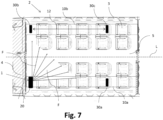
- Fig. 7 shows a schematic top view of an aircraft cabin 2 comprising the system 1 according to an embodiment of the invention.
- the layout of the aircraft cabin 2 shown in Fig. 7 shows the application of the system 1, in which the camera module 20 is configured to monitor the passenger seats 3 from an FWD section to an AFT section in the airplane.
- the camera 21 of the camera module 20 is thus orientated towards a backward direction of the aircraft cabin 2.
- the aircraft cabin 2 includes an aisle 5 in the center of the aircraft cabin extending a the longitudinal direction L.
- the aircraft cabin 2 comprises a first supply channel 10a and a second supply channel 10b.
- the camera module 10a is arranged on the first supply channel 10a and a first lighting module 30a is arranged on the same first supply channel 10a.
- a second lighting module 10b and a third lightning module 30c are arranged on the second supply channel 10b.
- the system 1 integrated into the aircraft cabin 2 of this embodiment is based on the system 1 described so far.
- the camera module 20 of the system 1 is arranged next to a monument 4 and the camera orientated substantially away from the monument 4.
- the monument 4 may be a galley, a toilet or simply a separation wall between section of the aircraft cabin 2.
- the field of view F in a horizontal direction, i.e. parallel to a floor of the aircraft cabin, of the camera 21 is indicated in Fig. 7 as being approximately 90°. In this case, it is enough to be able to view at least partially each passenger seat 3 arranged in the aircraft cabin.
- the field of view F of the camera 21 is more than 100° or between 100° and 110°, such as e.g.. 103°.
- a vertical field of view may be between 10° and 20°, in particular 15°, but can be less or more depending on the layout of the aircraft cabin 2.
- the second lightning module 30 is arranged at the opposite side of the aisle 5 of the aircraft cabin 2. As indicated, a module distance 12 corresponding four seat rows, e.g. about 4 meters, the first and third lightning modules 30a, 30c are installed in the respective supply channels 10a, 10b.
- the system 1 further comprises a control device 40 (not shown in Fig. 7 ) connected to the camera module 20 and each of the lightning modules 30a-c.
- the control device 40 is configured to control the camera 21 in the control module 20 and each of the infrared light sources 31 in the respective lighting modules 30.
- the aircraft cabin 2 further comprises a display (not shown) of system 1.
- the control device 40 is adapted to receive a video signal containing information about the captured image by the camera 21 and send the video signal to the display.
- the video signal can thereby have any format suitable for the task, such as NTSC, PAL, etc..
- the display is directed to a cabin attendant seat, CAS of the aircraft cabin 2 for monitoring the passengers from the CAS.
- Fig. 8 shows a schematic top view of an aircraft cabin 2 comprising the system 1 according to a further embodiment of the invention.
- the system 1 integrated into the aircraft cabin 2 of this embodiment is based on the system 1 described so far, in particular of the system 1 described with reference to Fig. 7 .
- the system 1 is orientated to monitor passengers from a AFT section toward a FWD section in the airplane.
- the camera 21 of the camera module 20 is directed towards the front of the aircraft cabin 2.
- Fig. 9 shows a schematic top view of an aircraft cabin 2 comprising the system 1 according to a further embodiment of the invention.
- the system 1 integrated into the aircraft cabin 2 of this embodiment is based on the system 1 described so far, in particular of the systems 1 described with reference to Fig. 7 and 8 .
- the system 1 is configured again to monitor the passenger seats 3 from an FWD section to an AFT section in the airplane.
- the camera 21 is thus orientated towards a backward direction of the aircraft cabin.
- the system 1 comprises seven lightning modules 30a-g, from which the first to third lightning modules 30a-c are arranged on the first supply channel 10a, and the fourth to seventh lightning modules 30d-g are arranged on the second lightning channel 10b located on the opposite side of the aisle 5.
- a module distance 12 between the camera module 20 and the next first lightning module 30a or between the lightning modules 30a-g on the same supply channel 10, 10b corresponds to about 5 seat rows, which is e.g. about 5 meters, along the longitudinal direction L of the aircraft cabin 2 or the airplane.
- a first viewing cone area 11 and a second viewing cone area I2 are indicated in Fig. 9 .
- the first viewing cone area I1 represents the viewing of the camera 21 in the camera module 20 in a dark condition of the aircraft cabin, i.e. when ambient light is dimmed or switched off, without the additional infrared light sources 31 in the respective lighting modules 30a-g.
- the second viewing cone area I2 indicates the viewing area of the camera 21 in the dark condition of the aircraft cabin 2, when the infrared light sources 31 of each of the lighting modules 30a-g are switched on.
- Fig. 10 shows a flow diagram of a method for monitoring an aircraft cabin 2 according to a further embodiment of the invention.
- the method for monitoring an aircraft cabin comprises the steps of emitting S1 infrared light by an infrared light source 31 of a lighting module 30 arranged at a first position 30a in a recess 11 of a supply channel 10, wherein the supply channel 10 extends in a longitudinal direction L of the aircraft cabin 2 and wherein the recess 11 extends along the longitudinal direction L.
- the method further comprises monitoring S2 the aircraft cabin 2 by a camera 21 of a camera module 20 arranged at a second position 20a in the recess 11 of the supply channel 10.
Landscapes
- Engineering & Computer Science (AREA)
- Physics & Mathematics (AREA)
- Computer Networks & Wireless Communication (AREA)
- General Physics & Mathematics (AREA)
- Radar, Positioning & Navigation (AREA)
- Remote Sensing (AREA)
- Multimedia (AREA)
- Signal Processing (AREA)
- Aviation & Aerospace Engineering (AREA)
- Electromagnetism (AREA)
- Studio Devices (AREA)
- Closed-Circuit Television Systems (AREA)
Abstract

Description
- The invention relates to a system for an aircraft cabin as well as a method for monitoring an aircraft cabin. The invention is furthermore concerned with an aircraft cabin containing such a system.
- According to the new flight regulation JAR §25.785H2 "direct view" the aisle has to be visible within the direct view from a cabin attendant seat, CAS, for safety needs of the passengers. Furthermore, passengers standing up from the passenger seat should be visible from the CAS. This applies to bright lightning conditions and dark lightning conditions in the cabin during a cruise of the aircraft.
- Typically, cameras and displays are installed in the aircraft cabin to fulfill these requirements. Cameras of such a camera-based direct view system can be integrated into a monument, such as a wall on the backside of a galley, a toilet or a separation wall, of an aircraft cabin. By this, the position of the camera is dependent on the cabin layout, which might be different for different aircrafts. Furthermore, the implementation of such a system needs multiple components to be adapted, which involves the camera position and the camera orientation in the monument. In addition, in order to cover the first rows of the passenger seats the viewing angle of such a monument-based camera has to be very large, typically nearly 180 degree.
- Another issue is to ensure the viewing of a passenger within a cabin during dark lighting conditions, which is usually applied during nighttime, for example on intercontinental flights. A regular camera sensitive in the visible spectral range has a very limited viewing cone and viewing distance in such dark conditions. Therefore, typically a camera able sensitive in the infrared spectrum is used to monitor the cabin for improved visibility.
- The problem of the present invention is thus to provide a camera system for improved monitoring of an aircraft cabin.
- According to the invention, this problem is solved in each case by the subject matters of the independent claims.
- According to a first aspect of the invention, a system for an aircraft cabin is provided. The system comprises at least one supply channel extending in a longitudinal direction of the aircraft cabin and including a recess along the longitudinal direction for installing supply modules, a camera module arranged at a first position of the recess of the supply channel, the camera module includes a camera configured to capture images in the visible spectral range and in the infrared spectral range, wherein the camera is directed towards passenger seats, at least one lighting module arranged at a second position of the recess of the supply channel, the at least one lighting module including an infrared light source configured to emit light in the infrared spectral range, a control device connected to the camera module and the at least one lighting module, wherein the control device is configured to control the camera and the infrared light source.
- According to a second aspect of the invention, an aircraft cabin comprising a system according to the invention is provided.
- According to a third aspect of the invention, a method for monitoring an aircraft cabin is provided. The method comprises the steps of emitting infrared light by an infrared light source of a lighting module arranged at a first position in a recess of a supply channel, wherein the supply channel extends in a longitudinal direction of the aircraft cabin and wherein the recess extends along the longitudinal direction, monitoring the aircraft cabin by a camera of a camera module arranged at a second position in the recess of the supply channel.
- A fundamental concept of the invention is to use a camera to monitor the aisle(s) and the passenger seats of an aircraft cabin. The images or videos captured or recorded by the camera may be displayed in real time on a monitor or display visible to the cabin crew. The camera is installed in a camera module, which is arranged or installed in a recess of a supply channel, which typically is a passenger supply channel, PSC, of the aircraft cabin. In order to recognize passengers that stand up from their seats during dark lightning conditions in the aircraft cabin, the camera includes a sensor or detector, which is sensitive in the visible and infrared spectral range. For further improving the visibility of the passengers on such images, a separate lightning module is provided and configured to illuminate the aircraft cabin with infrared light. A part of the emitted infrared light is reflected at the passengers and other objects and captured by the camera. In this way, the system is able to monitor passengers during bright and also dark lightning conditions in the cabin.
- The PSC typically extends along a longitudinal direction of the aircraft cabin and is arranged above the passenger seats. The recess of such a PSC extends along the longitudinal direction and is configured to receive supply modules. The recess may have a rail, on which the supply modules can be fixed by e.g. clips. A supply module may be a passenger supply unit, PSU, which provides ventilation, oxygen supply, a reading light, and/or a button for calling a cabin attendant. The camera module and the lightning module are configured as such a supply module to be received by the PSC. Furthermore, one or more spacers or cover modules may be placed in the recess to cover the recess between the supply modules.
- A particular advantage in the solution according to an aspect of the invention is that the position of the camera module and the infrared module/s can be easily moved along the recess of the supply channel, thus be adapted to a special cabin layout. This makes the system very flexible. Since the position of the camera module and the position of the infrared module can be easily adapted on the supply channel, the system is thus easily appliable in aircraft having different layouts.
- One of the key feature of the system of the present invention is thus the flexibility it provides regarding viewing angle and orientation, cabin position and cabin layout. The camera viewing distance can be simply adjusted for the customer needs by the number of lightning modules. Furthermore, the system is provided with its own control device, which makes it independent of the board computer. The system of the present invention is thus a standalone system without being dependent on other cabin elements and on changes of already existing components.
- The first position in the supply channel, where the camera module is arranged or installed is thereby different from the second position, where the lightning module is arranged or installed. This module distance can have several meters, so that the entire system is able to illuminate and monitor objects such as passengers up to a distance of more than 10 m, for example, 12 m, 15 m or more, thus being able to monitor an aircraft cabin of relatively large size with only one camera. In case of very large aircraft cabins, the system may include one or more additional camera modules and respective lightning modules for monitoring the aircraft cabin.
- Furthermore, although the present invention is explained in the context of an aircraft cabin, it is understood that the described system may also be applied to passenger cabins in other vehicles, such as e.g. busses.
- Advantageous embodiments and further developments emerge from the description with reference to the figures.
- According to some embodiments of the system according to the invention, at least a part of each passenger seat in the aircraft cabin is within a field of view of the camera. This ensures the visibility of all passengers in the aircraft cabin, thus provides improved safety.
- According to some embodiments of the system according to the invention, the field of view of the camera is more than 90°. This ensures that the aircraft cabin can be monitored with only one camera. Preferably, an angle of more than 100°, more preferably between 100° and 110° is used. This angle is referred to the horizontal angle in the projection plane to the floor of the aircraft. A vertical angle of the field of view is typically between 10° to 20°, preferably 15°, however, not limited to these angles.
- According to some embodiments aspects of the system according to the invention, the camera is arranged on a rotatable mount. In this way, the orientation of the camera can be adjusted depending on the position of the camera module in the supply channel and the layout of the aircraft cabin. This embodiment thus provides more flexibility to the system.
- According to some embodiments of the system according to the invention, the lighting module comprises an indicator light configured to emit light in a predetermined visible spectral range. Furthermore, the control device is configured to switch the indicator light depending on whether or not the infrared light source is emitting infrared light. In this way, the passengers are aware when the cabin attendants are monitoring the aircraft cabin. This increases the safety of the passengers.
- According to some embodiments of the system according to the invention, the indicator light is configured to emit light in the red spectral range, e.g. the light having a wavelength between 600 nm and 650 nm. In this way, the light does not appear bright to a passenger in a dark condition of the aircraft cabin, and thus does not disturbs the passengers during night time.
- Preferably, the infrared light source and the indicator light are the only light sources of the lighting module. This ensures that no additional light source is present that may disturb the monitoring of the aircraft cabin by the system and the passengers during night time.
- According to some embodiments of the system according to the invention, the infrared light source is configured to emit light in the near-infrared spectral range, which is preferably within 800 nm to 1050 nm, in particular 850 nm or 940 nm. In this way, the light can be easily detected by usual, e.g. silicon-based, detectors in the camera, and there is need for special detectors sensitive in the mid-infrared. This embodiment thus reduces the cost of the system.
- According to some embodiments of the system according to the invention, the infrared light source is arranged in the lightning module for emitting light only in a direction away from a direction toward the camera module. This prevents the infrared light source dazzling the camera, i.e. it avoids a bright spot at the location of the infrared light source on the image captured by the camera. On the other hand, by emitting the light in the direction opposite to the camera, the amount of reflected light from an object, from the passengers, collected by the camera is optimized. Thus, the quality of the images is improved, and the visible distance to the camera in the aircraft cabin is increased.
- According to some embodiments of the system according to the invention, the system further comprises a display, wherein the control device is adapted to receive a video signal containing information about the captured image by the camera and send the video signal to the display. Through the display, the staff, such as the cabin attendants can thus observe the aisles and passengers sitting and standing up from their passenger seats.
- According to some embodiments of the system according to the invention, the display is directed to at least one cabin attendant seat, CAS, of the aircraft cabin. The cabin attendant can thus observe the aircraft cabin and the passengers also during take-off, taxing and landing, when the cabin attendant themselves have to be sitting on their seat.
- According to some embodiments of the system according to the invention, the camera module and the at least one lighting module are arranged on the same supply channel. This represents the most compact way of installing the system in the aircraft cabin.
- According to some embodiments of the system according to the invention, the system further comprises a first supply channel and a second supply channel, wherein the camera module is arranged on the first supply channel and the at least one lighting module is arranged on the second supply channel. In this way, the system can be distributed across the aircraft cabin to monitor large aircraft cabins in large aircrafts.
- According to some embodiments of the system according to the invention, the system further comprising a first supply channel, a second supply channel, a first lighting module and a second lighting module, wherein the camera module and the first lighting module are arranged on a first supply channel, wherein the second lighting module is arranged on a second supply channel. In this way, the distance visible to the camera, in particular at dark conditions, is increased.
- The above embodiments and further developments can be combined with each other as desired, if useful. In particular, all features of the system for the aircraft cabin are transferable to the aircraft cabin and/or the method for capturing an image of passengers in an aircraft cabin, and vice versa. Further possible embodiments, further developments and implementations of the invention also comprise combinations, not explicitly mentioned, of features of the invention described before or below with respect to the embodiments. In particular, the skilled person will thereby also add individual aspects as improvements or additions to the respective basic form of the present invention.
- The present invention is explained more specifically below on the basis of the exemplary embodiments indicated in the schematic figures, in which:
- Fig. 1A-C
- show schematic illustrations of a system for an aircraft cabin according to an embodiment of the invention;
- Fig. 2
- shows a schematic illustration of an example camera module of the system according to an embodiment of the invention;
- Fig. 3
- shows a schematic illustration of an example lighting module of the system according to an embodiment of the invention;
- Fig. 4
- shows a schematic illustration of an example camera module of the system according to a further embodiment of the invention;
- Fig. 5
- shows a schematic illustration of an example lighting module of the system according to a further embodiment of the invention;
- Fig. 6
- shows a schematic illustration of an aircraft cabin comprising the system according to a further embodiment of the invention;
- Fig. 7
- shows a schematic top view of an aircraft cabin comprising the system according to an embodiment of the invention;
- Fig. 8
- shows a schematic top view of an aircraft cabin comprising the system according to a further embodiment of the invention;
- Fig. 9
- shows a schematic top view of an aircraft cabin comprising the system according to a further embodiment of the invention; and
- Fig. 10
- shows a flow diagram of a method for monitoring an aircraft cabin according to an embodiment of the invention.
- The accompanying figures are intended to convey a further understanding of the embodiments of the invention. They illustrate embodiments and are used in conjunction with the description to explain principles and concepts of the invention. Other embodiments and many of the cited advantages emerge in light of the drawings. The elements of the drawings are not necessarily shown to scale in relation to one another. Direction-indicating terminology such as for example "at the top", "at the bottom", "on the left", "on the right", "above", "below", "horizontally", "vertically", "at the front", "at the rear" and similar statements are merely used for explanatory purposes and do not serve to restrict the generality to specific configurations as shown in the figures.
- In the figures of the drawing, elements, features and components that are the same, have the same function and have the same effect are each provided with the same reference signs - unless explained otherwise.
-
Fig. 1A-C show schematic illustrations of asystem 1 for anaircraft cabin 2 according to an embodiment of the invention. -
Fig. 1 A is a side view of thesystem 1 arranged in anaircraft cabin 2. Thesystem 1 comprises at least onesupply channel 10 arranged in theaircraft cabin 2. The supply channel is a passenger supply channel, PSC, which is arranged above the passenger seats 3. Thesupply channel 10 extends in a longitudinal direction L of theaircraft cabin 2, wherein the longitudinal direction L is parallel to a longitudinal center axis of the airplane. Thesupply channel 10 includes arecess 11 along the longitudinal direction L for installing supply modules. These supply modules may include a passenger supply units, PSU, 50 (not shown inFig. 1 ) comprising oxygen supply, a reading light, a button for calling a cabin attendant, ventilations, and so on. The supply modules can be installed at any arbitrary position of therecess 11 of the supply channel. In some embodiments, the supply modules can slide along therecess 11 so that fine adjustments are possible. Spacers are arranged between the module in order to hide the cabling, which is provided above these to connect the modules to the board electronics, such as the computer. In some embodiments, therecess 11 comprises a rail for installing the modules by, e.g. clips. - The
system 1 comprises acamera module 20 arranged at afirst position 11a of therecess 11 of thesupply channel 10. The module is thus installed in therecess 11 of thesupply channel 10a. Thefirst position 11a may be any kind of position in the aircraft. In some embodiments, thecamera module 20 is arranged next to a monument 4 (not shown inFig. 1 ), which may be a galley, a toilet or a separation wall between different sections of theaircraft cabin 2. Thecamera module 20 includes acamera 21, which is configured to capture images in the visible spectral range and in the infrared spectral range. Thecamera 21 thus includes a sensor or detector, which is sensitive in the visible and infrared spectral range. The sensor may be any suitable type of sensor, such as e.g. a CCD or CMOS sensor. - In
Fig. 1 , it is shown that thecamera 21 is directed towards passenger seats 3. A field of view F of thecamera 21 is indicated schematically. In some embodiments, thecamera 21 is arranged and orientated such that at least a part of eachpassenger seat 3 in theaircraft cabin 2 is within the field of view F of thecamera 21. - The
system 1 further comprises at least onelighting module 30 arranged at asecond position 11b of therecess 11 of thesupply channel 10. In further embodiments, thesystem 1 comprises a plurality oflighting modules 30. Thelighting module 30 includes an infraredlight source 31, which is configured to emit light in the infrared spectral range. In this embodiment, thelightning module 30 is located amodule distance 12 away along thesupply channel 21. In this embodiment, themodule distance 12 is only about a few meters, e.g. about 2 meters. In further embodiments, themodule distance 12 is about 3m, about 4m, about 5m, or more. - The
system 1 further comprises acontrol device 40, which is connected to thecamera module 20 and the at least onelighting module 30. Thecontrol device 40 is configured to control thecamera 21 and the infraredlight source 31. Thecontrol device 40 is thus able to switch on and off thecamera 21 for capturing images or videos for monitoring the passengers in theaircraft cabin 2. Thecontrol device 40 is further able to switch on and off the infraredlight source 31 of thelighting module 30. In the case of a plurality oflighting modules 30, thecontrol device 40 is connected to eachlighting module 30 to be able to switch on and off each infraredlight source 31 for extending the view of thecamera 21 in the dark conditions in theaircraft cabin 2. -
Fig. 1B shows the cross section A indicated inFig. 1A through thelighting module 30 arranged on thesupply channel 10. Thelighting module 30 is installed in therecess 11 of thesupply channel 10. The infraredlight source 31 is arranged underneath thesupply channel 10 and is provided in this embodiment with a lens, as will be described later, in order to direct the light in the desired direction. In some embodiments, the infraredlight source 31 is configured to emit light in the near-infrared spectral range, in particular within a wavelength range between 800 nm and 1050 nm, preferably at around 850 nm or 940 nm wavelength. Thecamera 21 is thus configured to detect the near-infrared light of within the spectral range between 800 nm and 1050 nm. In further embodiments, the infraredlight source 31 is configured as a mid-infrared source, emitting wavelengths e.g. between 1200 nm and 2000 nm. In these embodiments, thecamera 21 is configured to detect mid-infrared light of the same or similar spectral range. Application of the infraredlight sources 31 up to the far-infrared and thermos-coupled cameras are also thinkable. -
Fig. 1C shows the cross section B of thecamera module 20 arranged in therecess 11 of thesupply channel 10. Thecamera module 20 is installed in therecess 11 of thesupply channel 10. Thecamera 21 is arranged underneath thesupply channel 10. In this embodiment, thecamera 21 is directed slightly underneath thesupply channel 10 towards the seats of thepassenger seats 3 directed to the backside of theaircraft cabin 2. - In some embodiments, the
system 1 further comprises a display, wherein thecontrol device 40 is adapted to receive a video signal captured by thecamera 21 and send the video signal to the display. The video signal is then converted to images or a video displayed on the display. In some embodiments, the display is directed to at least one cabin attendant seat, CAS, of the aircraft cabin. The cabin attendants are then able to view the captured images or video during sitting on their seat, e.g. during take-off, taxi and landing. -
Fig. 2 shows a schematic illustration of anexample camera module 20 of thesystem 1 according to an embodiment of the invention. - In this perspective view of a
camera module 20, thecamera 21 is arranged on arotatable mount 22. By themount 22, thecamera 21 can be rotated and orientated about an angle, preferably about 360°. Acamera lens 23 is attached to thecamera 21 in order to provide a suitable field of view F. Thecamera module 20 has acamera circuit board 24 including microchips, by which parameters such as the exposure time, sensitivity, etc. of thecamera 21 can be controlled. Aconnector 24a connects an electrical harness or a cable the control device 40 (not shown inFig. 2 ). An A/C connector or any other suitable type of connector can be used to connect the module to further cables or thecontrol device 40. Thecamera circuit board 24 is arranged on acamera base panel 25. Underneath thecamera base panel 25, acamera lens cover 26 is attached through which the camera is able to monitor theaircraft cabin 2. Therefore, at least a part of the camera lens cover 26 is transparent in the visible and the infrared spectral range used by thecamera 21. Camera module attachment means 27 are located at the side of thecamera module 20 for attaching thecamera module 20 to therecess 11 of thesupply channel 10. The clip-shaped attachment means 27 shown inFig. 2 are suitable to attach thecamera module 20 to a rail comprised in therecess 11. Although a clip-shaped camera module attachment means 27 is shown inFig. 2 , any suitable type of camera module attachment means 27 can be used for attaching thecamera module 20 into therecess 11 of thesupply channel 10. -
Fig. 3 shows a schematic illustration of anexample lighting module 30 of thesystem 1 according to an embodiment of the invention. - The
lightning module 30 shown inFig. 3 shows an infrared circuit board 34, on which the infraredlight source 31 is attached in a lower side of the infrared circuit board 34. Aconnector 34a connects the infrared circuit board 34 with electrical harness or cables, such as a first wire 34b1 for a first side of the infrared circuit board 34 and a second wire 34b2 for a second side of the infrared circuit board 34. In this embodiment, the infrared circuit board thus has twoinfrared light sources 31, attached on the first and second side of the infrared circuit board 34. In further embodiments, only one infraredlight source 31 is installed or attached on the infrared circuit board 34. The infrared circuit board 34 is arranged on aninfrared base panel 35. Underneath theinfrared base panel 35, an infrared camera lens cover 36 including an infrared lens 32 (not shown inFig. 3 ) is attached through which the infrared light can be emitted. The infrared lens is thus transparent at least in part of the infrared spectral ranged thatlight source 31 is emitting infrared light. Lightning module attachment means 37 are located at the side of thelightning module 20 for attaching thecamera module 20 to thesupply channel 10. The clip-shaped attachment means 37 shown inFig. 3 are suitable to attach thecamera module 20 to a rail comprised in therecess 11. However, any suitably-shaped lightning module attachment means 37 can be used for this task. -
Fig. 4 shows a schematic illustration of anexample camera module 20 of thesystem 1 according to an embodiment of the invention. - The
camera module 20 shown inFig. 4 is based on thecamera module 20 shown inFig. 2 and can be implemented into any embodiments of thesystem 1 described herein. Thecamera module 20 comprises acamera base panel 25, on which camera module attachment means 27 are formed for attaching thecamera module 20 onto thesupply channel 11, more precisely into therecess 11 of the supply channel. Thecamera module 20 further comprises acamera lens cover 26, which is partly transparent in the visible and infrared range used by thecamera 21, which is arranged behind thecamera lens cover 26. Shown inFig. 4 is anupper panel 28 of thecamera module 20, which covers thecamera circuit board 24 and thecamera 21 with thecamera lens 23 and therotatable mount 22. -
Fig. 5 shows a schematic illustration of anexample lighting module 30 of thesystem 1 according to an embodiment of the invention. - The
lightning module 30 shown inFig. 5 is based on thelightning module 30 shown inFig. 3 and can be implemented into any embodiments of thesystem 1 described herein. Similar to the embodiment of thelightning module 30 shown inFig. 3 , thelightning module 30 of this embodiment comprises ainfrared base panel 35 and an infraredlower panel 36, which encloses aninfrared lens 32 through which infrared light can be emitted by the infrared light source 31 (not shown inFig. 5 ). Anupper panel 38 of thelightning module 30 is attached to theinfrared base panel 35 and covers an infrared circuit board 34, on which the infraredlight source 31 is attached. Thelightning module 31 further comprises anindicator light 33,which is configured to emit light in a predetermined visible spectral range. In this embodiment, theindicator light 33 is configured to emit light in the red light spectral range, e.g. between 600 nm and 650, and configured as an LED. In further embodiments, theindicator light 33 is configured to emit orange, yellow, green or blue light. In this embodiment, theindicator light 33 is integrated into the infraredlower panel 36. In further embodiments, theindicator light 33 is integrated into theinfrared lens 32 or theindicator light 33 is arranged behind theinfrared lens 32. The control device 40 (not shown inFig. 5 ) is connected to theindicator light 33 and configured to switch theindicator light 33 depending on whether or not the infraredlight source 31 is emitting infrared light. - In this embodiment, the infrared
light source 31 and theindicator light 33 are thus the only light-emitting elements of thelighting module 30. The infraredlight source 31 and theinfrared light module 30 as shown inFig. 5 can be arranged for emitting light into a cone of light, which is less than about 180°. The infraredlight source 31 and theinfrared light module 30 thus can be directed in a direction away from a direction toward thecamera module 20, so that no bright spots occur in the captured images. -
Fig. 6 shows a schematic illustration of anaircraft cabin 2 comprising thesystem 1 according to a further embodiment of the invention. - In the
aircraft cabin 2 shown inFig. 6 , asystem 1 as described above is integrated. Thesystem 1 comprises acamera module 20 and alightning module 30, which are arranged on thesupply channel 10. In this embodiment, thesupply channel 10 is a passenger supply channel, PSC. The PSC is located abovepassenger seats 3 and further includes severalpassenger supply units 50 above each row ofpassenger seats 3. - The
camera module 20 and thelightning module 30 of thesystem 1 of this this embodiment are similar to thecamera module 20 and thelightning module 30 as shown and described with reference toFig. 5 and6 . The infraredlight source 31 is arranged for emitting light substantially only in a direction away from a direction toward thecamera module 20. -
Fig. 7 shows a schematic top view of anaircraft cabin 2 comprising thesystem 1 according to an embodiment of the invention. - The layout of the
aircraft cabin 2 shown inFig. 7 shows the application of thesystem 1, in which thecamera module 20 is configured to monitor thepassenger seats 3 from an FWD section to an AFT section in the airplane. Thecamera 21 of thecamera module 20 is thus orientated towards a backward direction of theaircraft cabin 2. Theaircraft cabin 2 includes anaisle 5 in the center of the aircraft cabin extending a the longitudinal direction L. - The
aircraft cabin 2 comprises afirst supply channel 10a and asecond supply channel 10b. Thecamera module 10a is arranged on thefirst supply channel 10a and afirst lighting module 30a is arranged on the samefirst supply channel 10a. Asecond lighting module 10b and athird lightning module 30c are arranged on thesecond supply channel 10b. - The
system 1 integrated into theaircraft cabin 2 of this embodiment is based on thesystem 1 described so far. Thecamera module 20 of thesystem 1 is arranged next to amonument 4 and the camera orientated substantially away from themonument 4. Themonument 4 may be a galley, a toilet or simply a separation wall between section of theaircraft cabin 2. The field of view F in a horizontal direction, i.e. parallel to a floor of the aircraft cabin, of thecamera 21 is indicated inFig. 7 as being approximately 90°. In this case, it is enough to be able to view at least partially eachpassenger seat 3 arranged in the aircraft cabin. In further embodiments, the field of view F of thecamera 21 is more than 100° or between 100° and 110°, such as e.g.. 103°. A vertical field of view may be between 10° and 20°, in particular 15°, but can be less or more depending on the layout of theaircraft cabin 2. - The
second lightning module 30 is arranged at the opposite side of theaisle 5 of theaircraft cabin 2. As indicated, amodule distance 12 corresponding four seat rows, e.g. about 4 meters, the first andthird lightning modules respective supply channels - The
system 1 further comprises a control device 40 (not shown inFig. 7 ) connected to thecamera module 20 and each of thelightning modules 30a-c. Thecontrol device 40 is configured to control thecamera 21 in thecontrol module 20 and each of the infraredlight sources 31 in therespective lighting modules 30. - The
aircraft cabin 2 further comprises a display (not shown) of system 1.Thecontrol device 40 is adapted to receive a video signal containing information about the captured image by thecamera 21 and send the video signal to the display. The video signal can thereby have any format suitable for the task, such as NTSC, PAL, etc.. The display is directed to a cabin attendant seat, CAS of theaircraft cabin 2 for monitoring the passengers from the CAS. -
Fig. 8 shows a schematic top view of anaircraft cabin 2 comprising thesystem 1 according to a further embodiment of the invention. - The
system 1 integrated into theaircraft cabin 2 of this embodiment is based on thesystem 1 described so far, in particular of thesystem 1 described with reference toFig. 7 . - Different from the previous embodiment, the
system 1 is orientated to monitor passengers from a AFT section toward a FWD section in the airplane. Thecamera 21 of thecamera module 20 is directed towards the front of theaircraft cabin 2. -
Fig. 9 shows a schematic top view of anaircraft cabin 2 comprising thesystem 1 according to a further embodiment of the invention. - The
system 1 integrated into theaircraft cabin 2 of this embodiment is based on thesystem 1 described so far, in particular of thesystems 1 described with reference toFig. 7 and8 . - In the layout of the
aircraft cabin 2 shown inFig. 9 , thesystem 1 is configured again to monitor thepassenger seats 3 from an FWD section to an AFT section in the airplane. Thecamera 21 is thus orientated towards a backward direction of the aircraft cabin. - The
system 1 comprises sevenlightning modules 30a-g, from which the first tothird lightning modules 30a-c are arranged on thefirst supply channel 10a, and the fourth toseventh lightning modules 30d-g are arranged on thesecond lightning channel 10b located on the opposite side of theaisle 5. In this embodiment, amodule distance 12 between thecamera module 20 and the nextfirst lightning module 30a or between thelightning modules 30a-g on thesame supply channel aircraft cabin 2 or the airplane. - A first
viewing cone area 11 and a second viewing cone area I2 are indicated inFig. 9 . The first viewing cone area I1 represents the viewing of thecamera 21 in thecamera module 20 in a dark condition of the aircraft cabin, i.e. when ambient light is dimmed or switched off, without the additional infraredlight sources 31 in therespective lighting modules 30a-g. The second viewing cone area I2 indicates the viewing area of thecamera 21 in the dark condition of theaircraft cabin 2, when the infraredlight sources 31 of each of thelighting modules 30a-g are switched on. -
Fig. 10 shows a flow diagram of a method for monitoring anaircraft cabin 2 according to a further embodiment of the invention. - The method for monitoring an aircraft cabin comprises the steps of emitting S1 infrared light by an infrared
light source 31 of alighting module 30 arranged at afirst position 30a in arecess 11 of asupply channel 10, wherein thesupply channel 10 extends in a longitudinal direction L of theaircraft cabin 2 and wherein therecess 11 extends along the longitudinal direction L. The method further comprises monitoring S2 theaircraft cabin 2 by acamera 21 of acamera module 20 arranged at a second position 20a in therecess 11 of thesupply channel 10. - In the detailed description above, various features have been combined in one or more examples in order to improve the rigorousness of the illustration. However, it should be clear in this case that the above description is of merely illustrative but in no way restrictive nature. It serves to cover all alternatives, modifications and equivalents of the various features and exemplary embodiments. Many other examples will be immediately and directly clear to a person skilled in the art on the basis of his knowledge in the art in consideration of the above description.
- The exemplary embodiments have been chosen and described in order to be able to present the principles underlying the invention and their application possibilities in practice in the best possible way. As a result, those skilled in the art can optimally modify and utilize the invention and its various exemplary embodiments with regard to the intended purpose of use. In the claims and the description, the terms "including" and "having" are used as neutral linguistic concepts for the corresponding terms "comprising". Furthermore, use of the terms "a", "an" and "one" shall not in principle exclude the plurality of features and components described in this way.
- While at least one exemplary embodiment of the present invention(s) is disclosed herein, it should be understood that modifications, substitutions and alternatives may be apparent to one of ordinary skill in the art and can be made without departing from the scope of this disclosure. This disclosure is intended to cover any adaptations or variations of the exemplary embodiment(s). In addition, in this disclosure, the terms "comprise" or "comprising" do not exclude other elements or steps, the terms "a" or "one" do not exclude a plural number, and the term "or" means either or both. Furthermore, characteristics or steps which have been described may also be used in combination with other characteristics or steps and in any order unless the disclosure or context suggests otherwise. This disclosure hereby incorporates by reference the complete disclosure of any patent or application from which it claims benefit or priority.
-
- 1
- system
- 2
- aircraft cabin
- 3
- passenger seats
- 4
- monument
- 10
- supply channel
- 10a
- first supply channel
- 10b
- second supply channel
- 11
- recess
- 11a
- first position
- 11b
- second position
- 12
- module distance
- 20
- camera module
- 21
- camera
- 22
- rotatable mount
- 23
- camera lens
- 24
- camera circuit board
- 24a
- connector
- 24b
- cables
- 25
- camera base panel
- 26
- camera lens cover
- 27
- camera module attachment means
- 28
- camera upper panel
- 30
- lightning module
- 30a-g
- first to ninth lightning module
- 31
- light source
- 32
- infrared lens
- 33
- indicator light
- 34
- infrared circuit board
- 34a
- connector
- 34b1
- cables for first side
- 34b2
- cables for second side
- 35
- infrared base panel
- 36
- infrared lower panel
- 37
- Lightning module attachment means
- 38
- upper panel
- 40
- control device
- 50
- passenger supply unit
- A
- first cross section
- B
- second cross section
- F
- field of view
- I1, I2
- viewing cone areas
- L
- longitudinal direction
Claims (15)
- System (1) for an aircraft cabin (2), comprisingat least one supply channel (10) extending in a longitudinal direction (L) of the aircraft cabin (2) and including a recess (11) along the longitudinal direction (L) for installing supply modules,a camera module (20) arranged at a first position (11a) of the recess (11) of the supply channel (10), the camera module (20) includes a camera (21) configured to capture images in the visible spectral range and in the infrared spectral range, wherein the camera (21) is directed towards passenger seats (3),at least one lighting module (30, 30a-g) arranged at a second position (11b) of the recess (11) of the supply channel (10), the at least one lighting module (30) including an infrared light source (31) configured to emit light in the infrared spectral range,a control device (40) connected to the camera module (20) and the at least one lighting module (30), wherein the control device (40) is configured to control the camera (21) and the infrared light source (31).
- System (1) according to claim 1, wherein at least a part of each passenger seat (3) in the aircraft cabin (2) is within a field of view (F) of the camera (21).
- System (1) according to claim 2, wherein the field of view (F) of the camera (21) is more than 90°, in particular more than 100°.
- System (1) according to any of the preceding claims, wherein the camera is arranged on a rotatable mount.
- System (1) according to any of the preceding claims, wherein the lighting module (30, 30a-g) comprises an indicator light (33) configured to emit light in a predetermined visible spectral range, wherein the control device (40) is configured to switch the indicator light (33) depending on whether or not the infrared light source (31) is emitting infrared light.
- System (1) according to claim 5, wherein the indicator light (33) is configured to emit light in a red light spectral range.
- System (1) according to any of the preceding claims, wherein the infrared light source (31) is configured to emit light in the near-infrared spectral range.
- System (1) according to any of the preceding claims, wherein the infrared light source (31) is arranged in the lightning module (30, 30a-g) for emitting light only in a direction away from a direction toward the camera module (20).
- System (1) according to any of the preceding claims, further comprising a display, wherein the control device (40) is adapted to receive a video signal containing information about the captured image by the camera (21) and send the video signal to the display.
- System (1) according to claim 9, wherein the display is directed to at least one cabin attendant seat, CAS of the aircraft cabin (2).
- System (1) according to any of the preceding claims, wherein the camera module (20) and the at least one lighting module (30, 30a-g) are arranged on the same supply channel (11).
- System (1) according to any of the preceding claims, further comprising a first supply channel (10a) and a second supply channel (10b), wherein the camera module (21) is arranged on the first supply channel (10a) and the at least one lighting module is arranged on the second supply channel (10b).
- System (1) according to any of the preceding claims, further comprising a first supply channel (10a), a second supply channel (10b), a first lighting module (30a-g) and a second lighting module (30, 30a-g), wherein the camera module (20) and the first lighting module (30a-g) are arranged on a first supply channel (10a), wherein the second lighting module (30a-g) is arranged on a second supply channel (10b).
- Aircraft cabin (2) comprising the system (1) of any of the preceding claims.
- Method for monitoring an aircraft cabin (2), comprising the steps of:emitting (S1) infrared light by an infrared light source (31) of a lighting module (30, 30a-g) arranged at a first position (11a) in a recess (11) of a supply channel (10), wherein the supply channel (10) extends in a longitudinal direction (L) of the aircraft cabin (2) and wherein the recess (11) extends along the longitudinal direction (L), andmonitoring (S2) the aircraft cabin (2) by a camera (21) of a camera module (20) arranged at a second position (11b) in the recess (11) of the supply channel (10).
Priority Applications (2)
| Application Number | Priority Date | Filing Date | Title |
|---|---|---|---|
| EP23182173.7A EP4484300A1 (en) | 2023-06-28 | 2023-06-28 | System, aircraft cabin and method for monitoring an aircraft cabin |
| US18/755,139 US20250004134A1 (en) | 2023-06-28 | 2024-06-26 | System, aircraft cabin and method for monitoring an aircraft cabin |
Applications Claiming Priority (1)
| Application Number | Priority Date | Filing Date | Title |
|---|---|---|---|
| EP23182173.7A EP4484300A1 (en) | 2023-06-28 | 2023-06-28 | System, aircraft cabin and method for monitoring an aircraft cabin |
Publications (1)
| Publication Number | Publication Date |
|---|---|
| EP4484300A1 true EP4484300A1 (en) | 2025-01-01 |
Family
ID=87036178
Family Applications (1)
| Application Number | Title | Priority Date | Filing Date |
|---|---|---|---|
| EP23182173.7A Pending EP4484300A1 (en) | 2023-06-28 | 2023-06-28 | System, aircraft cabin and method for monitoring an aircraft cabin |
Country Status (2)
| Country | Link |
|---|---|
| US (1) | US20250004134A1 (en) |
| EP (1) | EP4484300A1 (en) |
Citations (4)
| Publication number | Priority date | Publication date | Assignee | Title |
|---|---|---|---|---|
| US20140176668A1 (en) * | 2011-04-01 | 2014-06-26 | Latecoere | Aircraft provided with a surveillance system |
| US20200307825A1 (en) * | 2019-03-28 | 2020-10-01 | Airbus Operations Gmbh | Camera module and system for surveillance of a passenger cabin of an aircraft, and aircraft |
| US20220024380A1 (en) * | 2020-07-27 | 2022-01-27 | Ford Global Technologies, Llc | Vehicle interior lighting system with activation control |
| US11673670B2 (en) * | 2020-09-28 | 2023-06-13 | Goodrich Lighting Systems GmbH & Co. KG | Aircraft passenger reading light having a visible and infrared light source |
-
2023
- 2023-06-28 EP EP23182173.7A patent/EP4484300A1/en active Pending
-
2024
- 2024-06-26 US US18/755,139 patent/US20250004134A1/en active Pending
Patent Citations (4)
| Publication number | Priority date | Publication date | Assignee | Title |
|---|---|---|---|---|
| US20140176668A1 (en) * | 2011-04-01 | 2014-06-26 | Latecoere | Aircraft provided with a surveillance system |
| US20200307825A1 (en) * | 2019-03-28 | 2020-10-01 | Airbus Operations Gmbh | Camera module and system for surveillance of a passenger cabin of an aircraft, and aircraft |
| US20220024380A1 (en) * | 2020-07-27 | 2022-01-27 | Ford Global Technologies, Llc | Vehicle interior lighting system with activation control |
| US11673670B2 (en) * | 2020-09-28 | 2023-06-13 | Goodrich Lighting Systems GmbH & Co. KG | Aircraft passenger reading light having a visible and infrared light source |
Also Published As
| Publication number | Publication date |
|---|---|
| US20250004134A1 (en) | 2025-01-02 |
Similar Documents
| Publication | Publication Date | Title |
|---|---|---|
| US11292610B2 (en) | Camera module and system for surveillance of a passenger cabin of an aircraft, and aircraft | |
| AU674456B2 (en) | Multi-camera closed circuit television system for aircraft | |
| US20170113801A1 (en) | Cabin monitoring system and cabin of aircraft or spacecraft | |
| US9499270B2 (en) | Supply module for passenger transport vehicles | |
| US8930088B2 (en) | Method for positioning at least one component, in particular a seat, in or on an aircraft or spacecraft, and aircraft or spacecraft | |
| CN102862683B (en) | Visual display on the flight deck of an aircraft | |
| AU758465B2 (en) | In flight camera system with electronic field of view switching | |
| US7151469B2 (en) | Surveillance system for aircraft interior | |
| CN102371948A (en) | Method for presenting an image in a vehicle | |
| US12054286B2 (en) | Methods and systems for lighting a vertical take-off and landing vehicle | |
| US11292609B2 (en) | Information projection and control system | |
| US20050225635A1 (en) | Video based security system | |
| KR20130130497A (en) | Helideck lighting diagnosis apparatus and method of the same | |
| US20210086903A1 (en) | Lighting system for an aircraft | |
| US20250004134A1 (en) | System, aircraft cabin and method for monitoring an aircraft cabin | |
| JP2012129908A (en) | Monitor system | |
| US10498957B2 (en) | Viewing system for in-flight refuelling | |
| US10819955B2 (en) | Aircraft provided with a surveillance system | |
| EP4470917A1 (en) | Display device, aircraft cabin and method for assembling an aircraft cabin | |
| US12168514B2 (en) | Interior aircraft lighting assembly, aircraft passenger service unit with an interior aircraft lighting assembly, and method of operating an interior aircraft lighting assembly | |
| HK1013755B (en) | Multi-camera closed circuit television system for aircraft |
Legal Events
| Date | Code | Title | Description |
|---|---|---|---|
| STAA | Information on the status of an ep patent application or granted ep patent |
Free format text: STATUS: UNKNOWN |
|
| PUAI | Public reference made under article 153(3) epc to a published international application that has entered the european phase |
Free format text: ORIGINAL CODE: 0009012 |
|
| STAA | Information on the status of an ep patent application or granted ep patent |
Free format text: STATUS: THE APPLICATION HAS BEEN PUBLISHED |
|
| AK | Designated contracting states |
Kind code of ref document: A1 Designated state(s): AL AT BE BG CH CY CZ DE DK EE ES FI FR GB GR HR HU IE IS IT LI LT LU LV MC ME MK MT NL NO PL PT RO RS SE SI SK SM TR |
|
| STAA | Information on the status of an ep patent application or granted ep patent |
Free format text: STATUS: REQUEST FOR EXAMINATION WAS MADE |
|
| 17P | Request for examination filed |
Effective date: 20250701 |
|
| GRAP | Despatch of communication of intention to grant a patent |
Free format text: ORIGINAL CODE: EPIDOSNIGR1 |
|
| STAA | Information on the status of an ep patent application or granted ep patent |
Free format text: STATUS: GRANT OF PATENT IS INTENDED |
|
| INTG | Intention to grant announced |
Effective date: 20260206 |