EP4484296A1 - Independent mitigation for isolation of electric motor - Google Patents
Independent mitigation for isolation of electric motor Download PDFInfo
- Publication number
- EP4484296A1 EP4484296A1 EP24184716.9A EP24184716A EP4484296A1 EP 4484296 A1 EP4484296 A1 EP 4484296A1 EP 24184716 A EP24184716 A EP 24184716A EP 4484296 A1 EP4484296 A1 EP 4484296A1
- Authority
- EP
- European Patent Office
- Prior art keywords
- propeller
- electric motor
- controller
- disconnect switch
- power management
- Prior art date
- Legal status (The legal status is an assumption and is not a legal conclusion. Google has not performed a legal analysis and makes no representation as to the accuracy of the status listed.)
- Pending
Links
Images


Classifications
-
- H—ELECTRICITY
- H02—GENERATION; CONVERSION OR DISTRIBUTION OF ELECTRIC POWER
- H02P—CONTROL OR REGULATION OF ELECTRIC MOTORS, ELECTRIC GENERATORS OR DYNAMO-ELECTRIC CONVERTERS; CONTROLLING TRANSFORMERS, REACTORS OR CHOKE COILS
- H02P29/00—Arrangements for regulating or controlling electric motors, appropriate for both AC and DC motors
- H02P29/0016—Control of angular speed of one shaft without controlling the prime mover
- H02P29/0027—Controlling a clutch between the prime mover and the load
-
- B—PERFORMING OPERATIONS; TRANSPORTING
- B64—AIRCRAFT; AVIATION; COSMONAUTICS
- B64D—EQUIPMENT FOR FITTING IN OR TO AIRCRAFT; FLIGHT SUITS; PARACHUTES; ARRANGEMENT OR MOUNTING OF POWER PLANTS OR PROPULSION TRANSMISSIONS IN AIRCRAFT
- B64D27/00—Arrangement or mounting of power plants in aircraft; Aircraft characterised by the type or position of power plants
- B64D27/02—Aircraft characterised by the type or position of power plants
- B64D27/30—Aircraft characterised by electric power plants
- B64D27/33—Hybrid electric aircraft
-
- B—PERFORMING OPERATIONS; TRANSPORTING
- B64—AIRCRAFT; AVIATION; COSMONAUTICS
- B64C—AEROPLANES; HELICOPTERS
- B64C11/00—Propellers, e.g. of ducted type; Features common to propellers and rotors for rotorcraft
- B64C11/30—Blade pitch-changing mechanisms
- B64C11/305—Blade pitch-changing mechanisms characterised by being influenced by other control systems, e.g. fuel supply
-
- B—PERFORMING OPERATIONS; TRANSPORTING
- B64—AIRCRAFT; AVIATION; COSMONAUTICS
- B64C—AEROPLANES; HELICOPTERS
- B64C13/00—Control systems or transmitting systems for actuating flying-control surfaces, lift-increasing flaps, air brakes, or spoilers
- B64C13/02—Initiating means
- B64C13/04—Initiating means actuated personally
- B64C13/042—Initiating means actuated personally operated by hand
- B64C13/0421—Initiating means actuated personally operated by hand control sticks for primary flight controls
-
- B—PERFORMING OPERATIONS; TRANSPORTING
- B64—AIRCRAFT; AVIATION; COSMONAUTICS
- B64C—AEROPLANES; HELICOPTERS
- B64C13/00—Control systems or transmitting systems for actuating flying-control surfaces, lift-increasing flaps, air brakes, or spoilers
- B64C13/02—Initiating means
- B64C13/04—Initiating means actuated personally
- B64C13/042—Initiating means actuated personally operated by hand
- B64C13/0423—Initiating means actuated personally operated by hand yokes or steering wheels for primary flight controls
-
- B—PERFORMING OPERATIONS; TRANSPORTING
- B64—AIRCRAFT; AVIATION; COSMONAUTICS
- B64D—EQUIPMENT FOR FITTING IN OR TO AIRCRAFT; FLIGHT SUITS; PARACHUTES; ARRANGEMENT OR MOUNTING OF POWER PLANTS OR PROPULSION TRANSMISSIONS IN AIRCRAFT
- B64D31/00—Power plant control systems; Arrangement of power plant control systems in aircraft
- B64D31/02—Initiating means
- B64D31/04—Initiating means actuated personally
-
- B—PERFORMING OPERATIONS; TRANSPORTING
- B64—AIRCRAFT; AVIATION; COSMONAUTICS
- B64D—EQUIPMENT FOR FITTING IN OR TO AIRCRAFT; FLIGHT SUITS; PARACHUTES; ARRANGEMENT OR MOUNTING OF POWER PLANTS OR PROPULSION TRANSMISSIONS IN AIRCRAFT
- B64D31/00—Power plant control systems; Arrangement of power plant control systems in aircraft
- B64D31/02—Initiating means
- B64D31/06—Initiating means actuated automatically
-
- B—PERFORMING OPERATIONS; TRANSPORTING
- B64—AIRCRAFT; AVIATION; COSMONAUTICS
- B64D—EQUIPMENT FOR FITTING IN OR TO AIRCRAFT; FLIGHT SUITS; PARACHUTES; ARRANGEMENT OR MOUNTING OF POWER PLANTS OR PROPULSION TRANSMISSIONS IN AIRCRAFT
- B64D31/00—Power plant control systems; Arrangement of power plant control systems in aircraft
- B64D31/16—Power plant control systems; Arrangement of power plant control systems in aircraft for electric power plants
- B64D31/18—Power plant control systems; Arrangement of power plant control systems in aircraft for electric power plants for hybrid-electric power plants
-
- B—PERFORMING OPERATIONS; TRANSPORTING
- B64—AIRCRAFT; AVIATION; COSMONAUTICS
- B64D—EQUIPMENT FOR FITTING IN OR TO AIRCRAFT; FLIGHT SUITS; PARACHUTES; ARRANGEMENT OR MOUNTING OF POWER PLANTS OR PROPULSION TRANSMISSIONS IN AIRCRAFT
- B64D35/00—Transmitting power from power plants to propellers or rotors; Arrangements of transmissions
- B64D35/02—Transmitting power from power plants to propellers or rotors; Arrangements of transmissions specially adapted for specific power plants
- B64D35/021—Transmitting power from power plants to propellers or rotors; Arrangements of transmissions specially adapted for specific power plants for electric power plants
- B64D35/022—Transmitting power from power plants to propellers or rotors; Arrangements of transmissions specially adapted for specific power plants for electric power plants of hybrid-electric type
- B64D35/025—Transmitting power from power plants to propellers or rotors; Arrangements of transmissions specially adapted for specific power plants for electric power plants of hybrid-electric type of parallel type
-
- F—MECHANICAL ENGINEERING; LIGHTING; HEATING; WEAPONS; BLASTING
- F02—COMBUSTION ENGINES; HOT-GAS OR COMBUSTION-PRODUCT ENGINE PLANTS
- F02C—GAS-TURBINE PLANTS; AIR INTAKES FOR JET-PROPULSION PLANTS; CONTROLLING FUEL SUPPLY IN AIR-BREATHING JET-PROPULSION PLANTS
- F02C6/00—Plural gas-turbine plants; Combinations of gas-turbine plants with other apparatus; Adaptations of gas-turbine plants for special use
- F02C6/20—Adaptations of gas-turbine plants for driving vehicles
-
- F—MECHANICAL ENGINEERING; LIGHTING; HEATING; WEAPONS; BLASTING
- F02—COMBUSTION ENGINES; HOT-GAS OR COMBUSTION-PRODUCT ENGINE PLANTS
- F02C—GAS-TURBINE PLANTS; AIR INTAKES FOR JET-PROPULSION PLANTS; CONTROLLING FUEL SUPPLY IN AIR-BREATHING JET-PROPULSION PLANTS
- F02C9/00—Controlling gas-turbine plants; Controlling fuel supply in air- breathing jet-propulsion plants
- F02C9/48—Control of fuel supply conjointly with another control of the plant
- F02C9/56—Control of fuel supply conjointly with another control of the plant with power transmission control
-
- F—MECHANICAL ENGINEERING; LIGHTING; HEATING; WEAPONS; BLASTING
- F02—COMBUSTION ENGINES; HOT-GAS OR COMBUSTION-PRODUCT ENGINE PLANTS
- F02C—GAS-TURBINE PLANTS; AIR INTAKES FOR JET-PROPULSION PLANTS; CONTROLLING FUEL SUPPLY IN AIR-BREATHING JET-PROPULSION PLANTS
- F02C9/00—Controlling gas-turbine plants; Controlling fuel supply in air- breathing jet-propulsion plants
- F02C9/48—Control of fuel supply conjointly with another control of the plant
- F02C9/56—Control of fuel supply conjointly with another control of the plant with power transmission control
- F02C9/58—Control of fuel supply conjointly with another control of the plant with power transmission control with control of a variable-pitch propeller
-
- Y—GENERAL TAGGING OF NEW TECHNOLOGICAL DEVELOPMENTS; GENERAL TAGGING OF CROSS-SECTIONAL TECHNOLOGIES SPANNING OVER SEVERAL SECTIONS OF THE IPC; TECHNICAL SUBJECTS COVERED BY FORMER USPC CROSS-REFERENCE ART COLLECTIONS [XRACs] AND DIGESTS
- Y02—TECHNOLOGIES OR APPLICATIONS FOR MITIGATION OR ADAPTATION AGAINST CLIMATE CHANGE
- Y02T—CLIMATE CHANGE MITIGATION TECHNOLOGIES RELATED TO TRANSPORTATION
- Y02T50/00—Aeronautics or air transport
- Y02T50/60—Efficient propulsion technologies, e.g. for aircraft
Definitions
- the present disclosure relates generally to a mitigation system for mechanically isolating an aircraft electric motor.
- Aircraft engine manufacturers are integrating electric motor into aircraft propulsion systems.
- the integration of electric devices and motors into an aircraft propulsion system create additional contingencies.
- the electric motor may be mechanically isolated from the propulsion system.
- Independent means of isolating the electric motor by a pilot may be utilized to safeguard engine and aircraft systems.
- current propulsion systems includes redundant systems to address contingencies, aircraft engine manufactures continuously seek improvements in engine performance, control, and propulsive efficiency.
- a power management system for a hybrid electric aircraft propulsion system including a turbine engine and an electric motor includes a controller that includes a memory device that is coupled to a processor, the memory includes a stored program with instructions executable by the processor, the stored program includes instructions for operating the electric motor.
- a propeller control is configured to generate a signal that is communicated to the controller for controlling a pitch angle of a propeller that is associated with the aircraft propulsion system.
- a disconnect switch is configured to trigger a mechanical decoupling device to decouple the electric motor from the aircraft propulsion system.
- the power management system includes a power control lever generating a signal communicated to the controller for controlling operation of the turbine engine and the electric motor, wherein the disconnect switch is mounted to the power control lever.
- the disconnect switch is actuatable independent of a position of the power control lever.
- the disconnect switch is automatically actuated based on a position of the power control lever.
- the mechanical decoupling device comprises an actuatable clutch.
- the propeller control and the controller are combined as a single controller.
- the propeller control comprises a feathering switch that is actuatable to send a signal to the controller for automatically changing the pitch angle of the propeller to a feathered position.
- the controller comprises a dual controller with a first channel and a second channel, wherein a signal from the disconnect switch and a signal from the propeller control are provided to separate ones of the first channel and the second channel to provide separate and independent signal paths for decoupling the electric motor and setting the pitch angle of the propeller.
- the power management system further comprises at least one sensing element configured to monitor at least one engine operating parameter.
- An aircraft propulsion system includes a turbine engine that is configured to generate a first mechanical power output from a combustion process to drive a propeller, an electric motor that is configured to generate a second mechanical power output to drive the propeller, a selectively operable mechanical decoupling device for mechanically decoupling the electric motor from the propeller, a controller that includes a memory device that is coupled to a processor, the memory includes a stored program with instructions executable by the processor, the stored program includes instructions for operating the turbine engine and the electric motor, a propeller control that is configured to generate a signal that is communicated to the controller for controlling a pitch angle of the propeller, and a disconnect switch that is configured to trigger the selectively operable mechanical decoupling device to mechanically decouple the electric motor from the propeller.
- the aircraft propulsion system includes a power control lever generating a signal communicated to the controller for controlling operation of the turbine engine and the electric motor, wherein the disconnect switch is mounted to the power control lever.
- the disconnect switch is actuatable independent of a position of the power control lever.
- the disconnect switch is automatically actuated based on a position of the power control lever.
- the propeller control is actuatable to change the pitch angle of the propeller to a feathered position.
- the controller comprises a dual controller with a first channel and a second channel, wherein a signal from the disconnect switch and a signal from the propeller control are provided to separate ones of the first channel and the second channel to provide separate and independent signal paths for decoupling the electric motor and setting the pitch angle of the propeller.
- the aircraft propulsion system further comprises at least one sensing element configured to monitor at least one engine operating parameter.
- a method of controlling operation of a hybrid electric aircraft propulsion system including a turbine engine and an electric motor includes monitoring an engine operating condition with at least one sensing element, providing a propeller control that is actuatable for controlling a pitch angle of a propeller, providing a disconnect switch that is actuatable to mechanically decouple an electric motor from the propeller, and configuring the propeller control to provide for changing the pitch angle to a feathered position and the disconnect switch to mechanically decouple the electric motor from the propeller in response to the monitored engine operating condition indicating operation of the electric motor outside of a predefined operating condition.
- the disconnect switch is configured to operate automatically to mechanically decouple the electric motor from the propeller in response to movement of a power lever to a predefined position.
- the propeller control comprises a feathering switch and is configured to automatically change the pitch of the propeller to the feathered position.
- the method includes configuring a controller to enable separate and independent actuation of the propeller control to move the propeller to the feathered position and actuation of the disconnect switch to mechanically decouple the electric motor from the propeller.
- Figure 1 schematically illustrates a hybrid electric aircraft propulsion system 20 that includes a turbine engine 30 and an electric motor 32.
- the example propulsion system 20 includes two independent means for a pilot to isolate the electric motor 32 in response to a detected fault condition. Isolation of the electric motor 32 is provided to mitigate effects on the aircraft electrical system 22 and the propulsion system 20.
- the turbine engine 30 is a turboprop engine that drives a propeller 34.
- the turbine engine includes a compressor section 24, a combustor section 26 and a turbine section 28 arranged along an engine axis A.
- the compressor section 24 drives air for compression and communication into the combustor section 26.
- the compressed air is mixed with fuel and ignited to generate an exhaust gas flow that expands through the turbine section 28 and is exhausted to the ambient environment.
- the example turbine section 28 is coupled to drive the compressor section 24.
- a power turbine 35 is configured to drive a shaft 37 that is coupled to drive the propeller 34 through a gearbox 36.
- the shaft 37 driven by the power turbine 35 provides a first mechanical power output that drives the propeller 34.
- the electric motor 32 is coupled to the gearbox 36 through a mechanical coupling 44 to provide a second mechanical power output that drives the propeller 34.
- the mechanical coupling 44 is shown schematically between the electric motor 32 and the gearbox 36, but may be coupled to provide the second mechanical power output to drive the propeller 34 in a different manner and remain within the contemplation and scope of this disclosure.
- turboprop turbine engine in the disclosed non-limiting embodiment, it should be understood that the concepts described herein are not limited to use with turboprops as the teachings may be applied to other types of gas turbine engines.
- An electrical system 22 provides electric energy to operate the electric motor 32.
- the electrical system 22 may include battery systems, generator systems and the electronics required to manage and control power generation and communication to the electric motor 32.
- the electric motor 22 is disclosed and described by way of example, the electric motor 32 may be a motor/generator that can provide both the addition of a mechanical drive input and the generation of electric energy. Additionally, the electric motor 32 is disclosed schematically as being coupled to the gearbox 36. However, the electric motor 32 may be mechanically coupled in other locations to provide the second drive input to the propeller 34.
- a controller 54 is schematically shown and governs operation of the propulsion system 20.
- the controller 54 receives inputs from sensing devices and pilot operated controls and generates signals utilized to control both the turbine engine 30 and the electric motor 32.
- a first sensing device 40 and a second sensing device 42 are located within the propulsion system 20 and provide information indicative of one or more engine operating parameters. Engine operating parameters may include, among other possible things, torque, shaft speed, current, voltage and temperature.
- the first sensing device 40 and the second sensing device 42 monitor an engine operating parameter and communicates that information to the controller 54.
- the controller 54 utilizes information from the first and second sensors 40, 42 to control and adjust operation of the propulsion system 20.
- the controller 54 may provide information to a cockpit display 56 for communicating engine operating parameters to a pilot.
- the display 56 may provide specific information on the each monitored engine parameter and/or simply confirm operation within desired and predefined operating parameters.
- a power lever 50 and a propeller control 52 provide control of the propulsion system 20.
- the power lever 50 generates signals utilized by the controller 54 to adjust engine power and thrust output.
- the propeller control 52 provides pitch adjustment for the blades 38 of the propeller 34.
- Operation of the example propulsion system 20 includes a means for isolating the electric motor 32 in case of a fault condition. Isolation of the electric motor 32 is utilized to protect the propulsion system 20 and the aircraft electrical system 22 coupled to the electric motor 32. In this disclosure, isolation of the electric motor 32 includes decoupling such that no mechanical input or output is provided to or provided by the electric motor 32. Physical separation of the electric motor 32 is not required. Moreover, where the electric motor 32 is a motor/generator, it may remain coupled in another manner that is not coupled to the propulsion system and prevents back driving.
- a fault condition in the electric motor 32 may reduce or prevent generation of the second mechanical power output that in turn impacts propulsion system operation.
- continued rotation of the electric motor 32 by way of the mechanical coupling through the gearbox 36 can generate arcing or uncontrolled generation of electric energy.
- the example propulsion system 20 includes isolation means to stop rotation of the electric motor 32 and to mechanically decouple the electric motor 32 from the propeller 34 and gearbox 36.
- a first mitigation path 84 is provided by operation of the propeller control 52 to adjust a pitch of the blades 38 to a feathered configuration.
- a second mitigation path 86 is provided by operation of a disconnect switch 48 that prompts actuation of a disconnect device 46 to mechanically decouple the electric motor 32 from the propeller 34 and gearbox 36.
- the disconnect device 46 comprises an actuatable clutch disposed between the electric motor 32 and the gearbox 36.
- the power management system 70 includes, among other things, the controller 54, the propeller control 52, the power lever 50 and the disconnect switch 48.
- the example controller 54 includes a processor 72 and a memory device 74 configured to store computer executable software instructions 76.
- the processor 72 is configured to execute the instructions embodied in the software instructions 76.
- the example controller 54 may be a separate controller dedicated to the power management system 70 are may be implemented as part of full-authority digital engine control (FADEC) or similar device, including an electronic engine control unit (EEC), engine control unite (ECU), electronic propeller control, propeller controller, electric motor controller (EMC), motor controller (MC), electric powertrain controller (EPC) and/or similar control devices and systems. Accordingly, the example controller 54 is a device and system for performing necessary computing or calculation operations of the power management system 70.
- FADEC full-authority digital engine control
- EEC engine control unite
- EMC electric motor controller
- EPC electric powertrain controller
- the example controller 54 includes, at a minimum, the processor 72 and the memory device 74.
- the memory device 74 provides for the storage of the software instructions 76.
- the software instructions 74 may be embodied in a computer program that uses data obtained from the first and second sensors 40, 42 along with data stored in the memory device 74 that may be required for its execution.
- the computer readable medium may be embodied in structures such as, but is not limited to, any type of disk including floppy disks, optical disks, CD-ROMs, magnetic-optical disks, read-only memories (ROMs), random access memories (RAMS), EPROMs, EEPROMs, magnetic or optical cards, application specific integrated circuits (ASICs), or any type of media suitable for storing electronic instructions, and each coupled to a computer system bus.
- the disclosed computer readable medium may be a non-transitory medium such as those examples provided.
- the disclosed memory device 74 may include any one or combination of volatile memory elements (e.g., random access memory (RAM, such as DRAM, SRAM, SDRAM, VRAM, etc.) and/or nonvolatile memory elements (e.g., ROM, hard drive, tape, CD-ROM, etc.).
- volatile memory elements e.g., random access memory (RAM, such as DRAM, SRAM, SDRAM, VRAM, etc.
- nonvolatile memory elements e.g., ROM, hard drive, tape, CD-ROM, etc.
- the software instructions 76 in the memory device 74 may include one or more separate programs, each of which includes an ordered listing of executable instructions for implementing logical functions.
- the disclosed controller 54 is configured to execute the software instructions 76 stored within the memory device 74, to communicate data to and from the memory device 28, and to generally control operations pursuant to the software instructions 76.
- the example controller 54 and propeller control 52 are shown schematically shown a separate unit, the propeller control 52 and the controller 54 may be a single combined controller.
- the example power management system 70 is show schematically with a separate controller 54 and propeller control 52, the features of the controller 54 and the propeller control 52 may be combined into a single control unit.
- the example power management system is disclosed by way of example as including features for mitigating effects of the electric motor 32, other control features as are necessary and utilized for control and operation of the propulsion system would be included and are within the scope and contemplation of this disclosure.
- the propeller control 52 provides a signal to the controller 54 that commands actuation of the propeller 34 and specifically commands changes in a pitch of the blades 38.
- the first mitigation path 84 is configured to enable the pilot to use the power control 52 to set the pitch of the blades 38 to a feathered configuration as shown in Figure 3 .
- the example feathered configuration arranges the blades 38 such that little to no rotation of the propeller 34 occurs.
- the pitch will arrange the blades 38 to have a minimal forward cross-section such that air passing through the blades 38 generates little to no rotation.
- the reduced rotation of the propeller 34 stops or slows rotation of the electric motor 32 to eliminate or reduce any electrical interaction that may be caused by rotation.
- the example propeller control 52 may be embodied in a control lever 80 that is actuatable by a pilot.
- the example propeller control 52 may be also be embodied as a feathering switch 82 that automatically sets the blades 38 to the feathered configuration that stops or minimizes rotation of the propeller 34.
- the second mitigation path 86 includes the disconnect switch 48 that is directly coupled to control the disconnect device 46.
- the disconnect device 46 provides for the mechanical decoupling of the electric motor 32 from the aircraft electrical system 22. Decoupling of the electric motor 32 prevents the introduction of electric power generated by a back driven electric motor 32 into the aircraft electrical system 22.
- the disconnect switch 48 operates independent of the controller 54 to provide the separate and independent second mitigation path 86.
- the example power management system 70 is schematically shown and illustrates the independent mitigation path 84, 86.
- the disconnect switch 48 is mounted to the power lever 50 to provide easy access to a pilot 58.
- the disconnect switch 48 is actuatable independent of a position of the power lever 50.
- the disconnect switch 48 may be automatically actuated based on a position of the power lever 50.
- the disconnect switch 48 may be automatically actuated when the power lever 50 is moved to an engine idle or off position.
- Other power lever positions may be utilized for triggering actuation of the disconnect switch 48.
- the example disconnect switch 48 may be embodied as a micro-switch.
- the disconnect switch 48 may further be embodied as other switch types and remain within the contemplation and scope of this disclosure.
- the first and second sensors 40, 42 monitor at least one engine operating parameter and communicate that information to the controller 54.
- the controller 54 process information from the sensors 40, 42 and communicates that information to the pilot 58 by way of the display 56 or other communication device.
- the information may be an alert, or simply be data that indicates the condition of the operating parameter.
- the pilot 58 may choose to act schematically indicated at 60 to isolate the electric motor 32.
- the power management system 70 is configured to enable the pilot 58 to isolate the electric motor 32 with the first mitigation path 84 by moving the blades 38 of the propeller 34 to the feathered configuration. In the feathered configuration, rotation of the propeller 34 is either stopped or slowed to reduce or prevent continued rotation of the electric motor 32.
- the power management system 70 is further configured to enable isolation of the electric motor 32 through actuation of the disconnect switch 48.
- the disconnect device 46 Upon actuation of the disconnect switch 48, the disconnect device 46 is activated and the mechanical connection between the electric motor 32 and the gearbox 36 and propeller 34 is disabled.
- the disconnect device 46 may be any electrical and/or mechanical device that is capable of mechanically decoupling the driving connection between the propeller 34 and the electric motor 32.
- One or both of the first and second mitigation path 84, 86 may be separately and independently engaged and utilized by the pilot to isolate the electric motor 32.
- FIG. 5 another example power management system 78 is schematically shown and includes a dual controller 62 having a first channel 64 and a second channel 66.
- the dual controller 62 provides redundancy in controller operation to add additional safeguards to operation.
- the disconnect switch 48 operates through one of the first and second channels 64, 66 and the propeller control 52 operates through the other of the first and second channels 64, 66.
- the propeller control 52 operates through the first channel 64 and the disconnect switch 48 operates through the second channel 66.
- Operation through different ones of the first and second channels 64, 66 provide separate and independent signal paths that maintain the separate and independent first and second mitigation paths 84, 86 for mechanically isolating the electric motor 32.
- the independent mitigation paths are without any one single failure point to provide robust electric motor isolation.
- the example power management system provides separate and independent electric motor mitigation paths without complex electronics and programming to provide robust electric motor mechanical isolation and mitigation.
- a power management system for a hybrid electric aircraft propulsion system 20 including a turbine engine 30 and an electric motor 32 includes a controller 54 that includes a memory device 74 that is coupled to a processor 72, the memory includes a stored program with instructions executable by the processor 72, the stored program includes instructions for operating the electric motor 32.
- a propeller control 52 is configured to generate a signal that is communicated to the controller 54 for controlling a pitch angle of a propeller 34 that is associated with the aircraft propulsion system 20.
- a disconnect switch 48 is configured to trigger a mechanical decoupling device 46 to decouple the electric motor 32 from the aircraft propulsion system 20.
- the power management system includes a power control lever that generates a signal that is communicated to the controller 54 for controlling operation of the turbine engine 30 and the electric motor 32.
- the disconnect switch 48 is mounted to the power control lever 50.
- the disconnect switch 48 is actuatable independent of a position of the power control lever 50.
- the disconnect switch 48 is automatically actuated based on a position of the power control lever 50.
- the mechanical decoupling device 46 includes an actuatable clutch.
- the propeller control 52 includes a lever 80 that is movable to change the pitch angle of the propeller 34 to a feathered position.
- the propeller control 52 includes a feathering switch 82 that is actuatable to send a signal to the controller 54 for automatically changing the pitch angle of the propeller 34 to a feathered position.
- the controller 54 includes a dual controller 62 with a first channel 64 and a second channel 66.
- a signal from the disconnect switch 48 and a signal from the propeller control 52 are provided to separate ones of the first channel 64 and the second channel 66 to provide separate and independent signal paths for decoupling the electric motor 32 and setting the pitch angle of the propeller 34.
- the power management systems further include at least one sensing element that is configured to monitor at least one engine operating parameter.
- An aircraft propulsion system includes a turbine engine 30 that is configured to generate a first mechanical power output from a combustion process to drive a propeller 34, an electric motor 32 that is configured to generate a second mechanical power output to drive the propeller 34, a selectively operable mechanical decoupling device for mechanically decoupling the electric motor 32 from the propeller 34, a controller 54 that includes a memory device 74 that is coupled to a processor 72, the memory includes a stored program with instructions executable by the processor 72, the stored program includes instructions for operating the turbine engine 30 and the electric motor 32, a propeller 34 control 52 that is configured to generate a signal that is communicated to the controller 54 for controlling a pitch angle of the propeller 34, and a disconnect switch 48 that is configured to trigger the selectively operable mechanical decoupling device to mechanically decouple the electric motor 32 from the propeller 34.
- the aircraft propulsion system includes a power control lever 50 that generates a signal that is communicated to the controller 54 for controlling operation of the turbine engine 30 and the electric motor 32.
- the disconnect switch 48 is mounted to the power control lever 50.
- the disconnect switch 48 is actuatable independent of a position of the power control lever 50.
- the disconnect switch 48 is automatically actuated based on a position of the power control lever 50.
- the propeller control 52 is actuatable to change the pitch angle of the propeller 34 to a feathered position.
- the controller 54 includes a dual controller 62 with a first channel 64 and a second channel 66.
- a signal from the disconnect switch 48 and a signal from the propeller control 52 are provided to separate ones of the first channel 64 and the second channel 66 to provide separate and independent signal paths for decoupling the electric motor 32 and setting the pitch angle of the propeller 34.
- the aircraft propulsion systems further includes at least one sensing element that is configured to monitor at least one engine operating parameter.
- a method of controlling operation of a hybrid electric aircraft propulsion system including a turbine engine 30 and an electric motor 32 includes monitoring an engine operating condition with at least one sensing element, providing a propeller control 52 that is actuatable for controlling a pitch angle of a propeller 34, providing a disconnect switch 48 that is actuatable to mechanically decouple an electric motor 32 from the propeller 34, and configuring the propeller control 52 to provide for changing the pitch angle to a feathered position and the disconnect switch 48 to mechanically decouple the electric motor 32 from the propeller 34 in response to the monitored engine operating condition indicating operation of the electric motor 32 outside of a predefined operating condition.
- the disconnect switch 48 is configured to operate automatically to mechanically decouple the electric motor 32 from the propeller 34 in response to movement of a power lever to a predefined position.
- the propeller control 52 includes a feathering switch 82 and is configured to automatically change the pitch of the propeller 34 to the feathered position.
- the method includes configuring a controller 54 to enable separate and independent actuation of the propeller control 52 to move the propeller 34 to the feathered position and actuation of the disconnect switch 48 to mechanically decouple the electric motor 32 from the propeller 34.
Landscapes
- Engineering & Computer Science (AREA)
- Aviation & Aerospace Engineering (AREA)
- Mechanical Engineering (AREA)
- Chemical & Material Sciences (AREA)
- Combustion & Propulsion (AREA)
- General Engineering & Computer Science (AREA)
- Automation & Control Theory (AREA)
- Power Engineering (AREA)
- Control Of Electric Motors In General (AREA)
- Electric Propulsion And Braking For Vehicles (AREA)
- Hybrid Electric Vehicles (AREA)
Abstract
Description
- The present disclosure relates generally to a mitigation system for mechanically isolating an aircraft electric motor.
- Aircraft engine manufacturers are integrating electric motor into aircraft propulsion systems. The integration of electric devices and motors into an aircraft propulsion system create additional contingencies. In the event of a fault involving the electric motor, the electric motor may be mechanically isolated from the propulsion system. Independent means of isolating the electric motor by a pilot may be utilized to safeguard engine and aircraft systems. While current propulsion systems includes redundant systems to address contingencies, aircraft engine manufactures continuously seek improvements in engine performance, control, and propulsive efficiency.
- A power management system for a hybrid electric aircraft propulsion system including a turbine engine and an electric motor, the power management system according to an aspect of the present invention includes a controller that includes a memory device that is coupled to a processor, the memory includes a stored program with instructions executable by the processor, the stored program includes instructions for operating the electric motor. A propeller control is configured to generate a signal that is communicated to the controller for controlling a pitch angle of a propeller that is associated with the aircraft propulsion system. A disconnect switch is configured to trigger a mechanical decoupling device to decouple the electric motor from the aircraft propulsion system.
- In embodiments of the above, the power management system includes a power control lever generating a signal communicated to the controller for controlling operation of the turbine engine and the electric motor, wherein the disconnect switch is mounted to the power control lever.
- In embodiments of any of the above, the disconnect switch is actuatable independent of a position of the power control lever.
- In embodiments of any of the above, the disconnect switch is automatically actuated based on a position of the power control lever.
- In embodiments of any of the above, the mechanical decoupling device comprises an actuatable clutch.
- In embodiments of any of the above, the propeller control and the controller are combined as a single controller.
- In embodiments of any of the above, the propeller control comprises a feathering switch that is actuatable to send a signal to the controller for automatically changing the pitch angle of the propeller to a feathered position.
- In embodiments of any of the above, the controller comprises a dual controller with a first channel and a second channel, wherein a signal from the disconnect switch and a signal from the propeller control are provided to separate ones of the first channel and the second channel to provide separate and independent signal paths for decoupling the electric motor and setting the pitch angle of the propeller.
- In embodiments of any of the above, the power management system further comprises at least one sensing element configured to monitor at least one engine operating parameter.
- An aircraft propulsion system according to another aspect of the present invention includes a turbine engine that is configured to generate a first mechanical power output from a combustion process to drive a propeller, an electric motor that is configured to generate a second mechanical power output to drive the propeller, a selectively operable mechanical decoupling device for mechanically decoupling the electric motor from the propeller, a controller that includes a memory device that is coupled to a processor, the memory includes a stored program with instructions executable by the processor, the stored program includes instructions for operating the turbine engine and the electric motor, a propeller control that is configured to generate a signal that is communicated to the controller for controlling a pitch angle of the propeller, and a disconnect switch that is configured to trigger the selectively operable mechanical decoupling device to mechanically decouple the electric motor from the propeller.
- In embodiments of the above, the aircraft propulsion system includes a power control lever generating a signal communicated to the controller for controlling operation of the turbine engine and the electric motor, wherein the disconnect switch is mounted to the power control lever.
- In embodiments of any of the above, the disconnect switch is actuatable independent of a position of the power control lever.
- In embodiments of any of the above, the disconnect switch is automatically actuated based on a position of the power control lever.
- In embodiments of any of the above, the propeller control is actuatable to change the pitch angle of the propeller to a feathered position.
- In embodiments of any of the above, the controller comprises a dual controller with a first channel and a second channel, wherein a signal from the disconnect switch and a signal from the propeller control are provided to separate ones of the first channel and the second channel to provide separate and independent signal paths for decoupling the electric motor and setting the pitch angle of the propeller.
- In embodiments of any of the above, the aircraft propulsion system further comprises at least one sensing element configured to monitor at least one engine operating parameter.
- A method of controlling operation of a hybrid electric aircraft propulsion system including a turbine engine and an electric motor, the method according to another aspect of the present invention, includes monitoring an engine operating condition with at least one sensing element, providing a propeller control that is actuatable for controlling a pitch angle of a propeller, providing a disconnect switch that is actuatable to mechanically decouple an electric motor from the propeller, and configuring the propeller control to provide for changing the pitch angle to a feathered position and the disconnect switch to mechanically decouple the electric motor from the propeller in response to the monitored engine operating condition indicating operation of the electric motor outside of a predefined operating condition.
- In embodiments of the above, the disconnect switch is configured to operate automatically to mechanically decouple the electric motor from the propeller in response to movement of a power lever to a predefined position.
- In embodiments of any of the above, the propeller control comprises a feathering switch and is configured to automatically change the pitch of the propeller to the feathered position.
- In embodiments of any of the above, the method includes configuring a controller to enable separate and independent actuation of the propeller control to move the propeller to the feathered position and actuation of the disconnect switch to mechanically decouple the electric motor from the propeller.
- Although the different examples have the specific components shown in the illustrations, embodiments of this disclosure are not limited to those particular combinations. It is possible to use some of the components or features from one of the examples in combination with features or components from another one of the examples.
- These and other features disclosed herein can be best understood from the following specification and drawings, the following of which is a brief description.
-
-
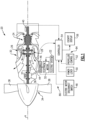
Figure 1 is a schematic view of an example aircraft propulsion system embodiment. -
Figure 2 is a schematic view of an example aircraft propulsion system and power management system. -
Figure 3 is a schematic view of an example propeller in a feathered configuration. -
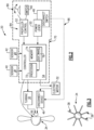
Figure 4 is a schematic view of the example power management system ofFigure 2 . -
Figure 5 is a schematic view of another example power management system. -
Figure 1 schematically illustrates a hybrid electricaircraft propulsion system 20 that includes aturbine engine 30 and anelectric motor 32. Theexample propulsion system 20 includes two independent means for a pilot to isolate theelectric motor 32 in response to a detected fault condition. Isolation of theelectric motor 32 is provided to mitigate effects on the aircraftelectrical system 22 and thepropulsion system 20. - In one disclosed example, the
turbine engine 30 is a turboprop engine that drives apropeller 34. The turbine engine includes acompressor section 24, acombustor section 26 and aturbine section 28 arranged along an engine axis A. Thecompressor section 24 drives air for compression and communication into thecombustor section 26. In thecombustor section 26, the compressed air is mixed with fuel and ignited to generate an exhaust gas flow that expands through theturbine section 28 and is exhausted to the ambient environment. Theexample turbine section 28 is coupled to drive thecompressor section 24. - A
power turbine 35 is configured to drive ashaft 37 that is coupled to drive thepropeller 34 through agearbox 36. Theshaft 37 driven by thepower turbine 35 provides a first mechanical power output that drives thepropeller 34. Theelectric motor 32 is coupled to thegearbox 36 through amechanical coupling 44 to provide a second mechanical power output that drives thepropeller 34. Themechanical coupling 44 is shown schematically between theelectric motor 32 and thegearbox 36, but may be coupled to provide the second mechanical power output to drive thepropeller 34 in a different manner and remain within the contemplation and scope of this disclosure. - Moreover, although depicted as a turboprop turbine engine in the disclosed non-limiting embodiment, it should be understood that the concepts described herein are not limited to use with turboprops as the teachings may be applied to other types of gas turbine engines.
- An
electrical system 22 provides electric energy to operate theelectric motor 32. Theelectrical system 22 may include battery systems, generator systems and the electronics required to manage and control power generation and communication to theelectric motor 32. Although theelectric motor 22 is disclosed and described by way of example, theelectric motor 32 may be a motor/generator that can provide both the addition of a mechanical drive input and the generation of electric energy. Additionally, theelectric motor 32 is disclosed schematically as being coupled to thegearbox 36. However, theelectric motor 32 may be mechanically coupled in other locations to provide the second drive input to thepropeller 34. - A
controller 54 is schematically shown and governs operation of thepropulsion system 20. Thecontroller 54 receives inputs from sensing devices and pilot operated controls and generates signals utilized to control both theturbine engine 30 and theelectric motor 32. In one example embodiment, afirst sensing device 40 and asecond sensing device 42 are located within thepropulsion system 20 and provide information indicative of one or more engine operating parameters. Engine operating parameters may include, among other possible things, torque, shaft speed, current, voltage and temperature. Thefirst sensing device 40 and thesecond sensing device 42 monitor an engine operating parameter and communicates that information to thecontroller 54. Thecontroller 54 utilizes information from the first andsecond sensors propulsion system 20. - The
controller 54 may provide information to acockpit display 56 for communicating engine operating parameters to a pilot. Thedisplay 56 may provide specific information on the each monitored engine parameter and/or simply confirm operation within desired and predefined operating parameters. - A
power lever 50 and apropeller control 52 provide control of thepropulsion system 20. Thepower lever 50 generates signals utilized by thecontroller 54 to adjust engine power and thrust output. Thepropeller control 52 provides pitch adjustment for theblades 38 of thepropeller 34. - Operation of the
example propulsion system 20 includes a means for isolating theelectric motor 32 in case of a fault condition. Isolation of theelectric motor 32 is utilized to protect thepropulsion system 20 and the aircraftelectrical system 22 coupled to theelectric motor 32. In this disclosure, isolation of theelectric motor 32 includes decoupling such that no mechanical input or output is provided to or provided by theelectric motor 32. Physical separation of theelectric motor 32 is not required. Moreover, where theelectric motor 32 is a motor/generator, it may remain coupled in another manner that is not coupled to the propulsion system and prevents back driving. - A fault condition in the
electric motor 32 may reduce or prevent generation of the second mechanical power output that in turn impacts propulsion system operation. Moreover, continued rotation of theelectric motor 32 by way of the mechanical coupling through thegearbox 36 can generate arcing or uncontrolled generation of electric energy. Accordingly, theexample propulsion system 20 includes isolation means to stop rotation of theelectric motor 32 and to mechanically decouple theelectric motor 32 from thepropeller 34 andgearbox 36. - In one example embodiment of the disclosed
propulsion system 20, two separate and independent mitigation paths are provided. Afirst mitigation path 84 is provided by operation of thepropeller control 52 to adjust a pitch of theblades 38 to a feathered configuration. Asecond mitigation path 86 is provided by operation of adisconnect switch 48 that prompts actuation of adisconnect device 46 to mechanically decouple theelectric motor 32 from thepropeller 34 andgearbox 36. In one example embodiment, thedisconnect device 46 comprises an actuatable clutch disposed between theelectric motor 32 and thegearbox 36. - Referring to
Figure 2 , with continued reference toFigure 1 , apower management system 70 of thepropulsion system 20 is shown schematically. Thepower management system 70 includes, among other things, thecontroller 54, thepropeller control 52, thepower lever 50 and thedisconnect switch 48. - The
example controller 54 includes a processor 72 and amemory device 74 configured to store computerexecutable software instructions 76. The processor 72 is configured to execute the instructions embodied in thesoftware instructions 76. - The
example controller 54 may be a separate controller dedicated to thepower management system 70 are may be implemented as part of full-authority digital engine control (FADEC) or similar device, including an electronic engine control unit (EEC), engine control unite (ECU), electronic propeller control, propeller controller, electric motor controller (EMC), motor controller (MC), electric powertrain controller (EPC) and/or similar control devices and systems. Accordingly, theexample controller 54 is a device and system for performing necessary computing or calculation operations of thepower management system 70. - The
example controller 54 includes, at a minimum, the processor 72 and thememory device 74. Thememory device 74 provides for the storage of thesoftware instructions 76. Thesoftware instructions 74 may be embodied in a computer program that uses data obtained from the first andsecond sensors memory device 74 that may be required for its execution. - Instructions for configuring and operating the processor 72 are embodied in the
software instructions 76 that may be stored on any combination of computer readable medium. The computer readable medium may be embodied in structures such as, but is not limited to, any type of disk including floppy disks, optical disks, CD-ROMs, magnetic-optical disks, read-only memories (ROMs), random access memories (RAMS), EPROMs, EEPROMs, magnetic or optical cards, application specific integrated circuits (ASICs), or any type of media suitable for storing electronic instructions, and each coupled to a computer system bus. The disclosed computer readable medium may be a non-transitory medium such as those examples provided. Moreover, the disclosedmemory device 74, may include any one or combination of volatile memory elements (e.g., random access memory (RAM, such as DRAM, SRAM, SDRAM, VRAM, etc.) and/or nonvolatile memory elements (e.g., ROM, hard drive, tape, CD-ROM, etc.). - The
software instructions 76 in thememory device 74 may include one or more separate programs, each of which includes an ordered listing of executable instructions for implementing logical functions. The disclosedcontroller 54 is configured to execute thesoftware instructions 76 stored within thememory device 74, to communicate data to and from thememory device 28, and to generally control operations pursuant to thesoftware instructions 76. Although theexample controller 54 andpropeller control 52 are shown schematically shown a separate unit, thepropeller control 52 and thecontroller 54 may be a single combined controller. Moreover, although the examplepower management system 70 is show schematically with aseparate controller 54 andpropeller control 52, the features of thecontroller 54 and thepropeller control 52 may be combined into a single control unit. Moreover, although the example power management system is disclosed by way of example as including features for mitigating effects of theelectric motor 32, other control features as are necessary and utilized for control and operation of the propulsion system would be included and are within the scope and contemplation of this disclosure. - Referring to
Figure 3 with continued reference toFigure 2 , thepropeller control 52 provides a signal to thecontroller 54 that commands actuation of thepropeller 34 and specifically commands changes in a pitch of theblades 38. Thefirst mitigation path 84 is configured to enable the pilot to use thepower control 52 to set the pitch of theblades 38 to a feathered configuration as shown inFigure 3 . The example feathered configuration arranges theblades 38 such that little to no rotation of thepropeller 34 occurs. The pitch will arrange theblades 38 to have a minimal forward cross-section such that air passing through theblades 38 generates little to no rotation. The reduced rotation of thepropeller 34 stops or slows rotation of theelectric motor 32 to eliminate or reduce any electrical interaction that may be caused by rotation. - The
example propeller control 52 may be embodied in acontrol lever 80 that is actuatable by a pilot. Theexample propeller control 52 may be also be embodied as a featheringswitch 82 that automatically sets theblades 38 to the feathered configuration that stops or minimizes rotation of thepropeller 34. - The
second mitigation path 86 includes thedisconnect switch 48 that is directly coupled to control thedisconnect device 46. Thedisconnect device 46 provides for the mechanical decoupling of theelectric motor 32 from the aircraftelectrical system 22. Decoupling of theelectric motor 32 prevents the introduction of electric power generated by a back drivenelectric motor 32 into the aircraftelectrical system 22. In one example embodiment, thedisconnect switch 48 operates independent of thecontroller 54 to provide the separate and independentsecond mitigation path 86. - Referring to
Figure 4 , with continued reference toFigure 2 , the examplepower management system 70 is schematically shown and illustrates theindependent mitigation path disconnect switch 48 is mounted to thepower lever 50 to provide easy access to apilot 58. In one example embodiment, thedisconnect switch 48 is actuatable independent of a position of thepower lever 50. In another example embodiment, thedisconnect switch 48 may be automatically actuated based on a position of thepower lever 50. For example, thedisconnect switch 48 may be automatically actuated when thepower lever 50 is moved to an engine idle or off position. Other power lever positions may be utilized for triggering actuation of thedisconnect switch 48. Theexample disconnect switch 48 may be embodied as a micro-switch. Thedisconnect switch 48 may further be embodied as other switch types and remain within the contemplation and scope of this disclosure. - In one example operational embodiment, the first and
second sensors controller 54. Thecontroller 54 process information from thesensors pilot 58 by way of thedisplay 56 or other communication device. The information may be an alert, or simply be data that indicates the condition of the operating parameter. In response to the information indicating operation of theelectric motor 32 outside of desired operating ranges, thepilot 58 may choose to act schematically indicated at 60 to isolate theelectric motor 32. Thepower management system 70 is configured to enable thepilot 58 to isolate theelectric motor 32 with thefirst mitigation path 84 by moving theblades 38 of thepropeller 34 to the feathered configuration. In the feathered configuration, rotation of thepropeller 34 is either stopped or slowed to reduce or prevent continued rotation of theelectric motor 32. - The
power management system 70 is further configured to enable isolation of theelectric motor 32 through actuation of thedisconnect switch 48. Upon actuation of thedisconnect switch 48, thedisconnect device 46 is activated and the mechanical connection between theelectric motor 32 and thegearbox 36 andpropeller 34 is disabled. Thedisconnect device 46 may be any electrical and/or mechanical device that is capable of mechanically decoupling the driving connection between thepropeller 34 and theelectric motor 32. One or both of the first andsecond mitigation path electric motor 32. - Referring to
Figure 5 , another examplepower management system 78 is schematically shown and includes adual controller 62 having afirst channel 64 and asecond channel 66. Thedual controller 62 provides redundancy in controller operation to add additional safeguards to operation. - In the example
power management system 78, thedisconnect switch 48 operates through one of the first andsecond channels propeller control 52 operates through the other of the first andsecond channels propeller control 52 operates through thefirst channel 64 and thedisconnect switch 48 operates through thesecond channel 66. Operation through different ones of the first andsecond channels second mitigation paths electric motor 32. The independent mitigation paths are without any one single failure point to provide robust electric motor isolation. - The example power management system provides separate and independent electric motor mitigation paths without complex electronics and programming to provide robust electric motor mechanical isolation and mitigation.
- A power management system for a hybrid electric
aircraft propulsion system 20 including aturbine engine 30 and anelectric motor 32, the power management system according to an exemplary embodiment of this disclosure, among other possible things includes acontroller 54 that includes amemory device 74 that is coupled to a processor 72, the memory includes a stored program with instructions executable by the processor 72, the stored program includes instructions for operating theelectric motor 32. Apropeller control 52 is configured to generate a signal that is communicated to thecontroller 54 for controlling a pitch angle of apropeller 34 that is associated with theaircraft propulsion system 20. Adisconnect switch 48 is configured to trigger amechanical decoupling device 46 to decouple theelectric motor 32 from theaircraft propulsion system 20. - In a further embodiment of the foregoing, the power management system includes a power control lever that generates a signal that is communicated to the
controller 54 for controlling operation of theturbine engine 30 and theelectric motor 32. Thedisconnect switch 48 is mounted to thepower control lever 50. - In a further embodiment of any of the foregoing power management systems, the
disconnect switch 48 is actuatable independent of a position of thepower control lever 50. - In a further embodiment of any of the foregoing power management systems, the
disconnect switch 48 is automatically actuated based on a position of thepower control lever 50. - In a further embodiment of any of the foregoing power management systems, the
mechanical decoupling device 46 includes an actuatable clutch. - In a further embodiment of any of the foregoing power management systems, the
propeller control 52 includes alever 80 that is movable to change the pitch angle of thepropeller 34 to a feathered position. - In a further embodiment of any of the foregoing power management systems, the
propeller control 52 includes a featheringswitch 82 that is actuatable to send a signal to thecontroller 54 for automatically changing the pitch angle of thepropeller 34 to a feathered position. - In a further embodiment of any of the foregoing power management systems, the
controller 54 includes adual controller 62 with afirst channel 64 and asecond channel 66. A signal from thedisconnect switch 48 and a signal from thepropeller control 52 are provided to separate ones of thefirst channel 64 and thesecond channel 66 to provide separate and independent signal paths for decoupling theelectric motor 32 and setting the pitch angle of thepropeller 34. - In a further embodiment of any of the foregoing, the power management systems further include at least one sensing element that is configured to monitor at least one engine operating parameter.
- An aircraft propulsion system according to another exemplary embodiment of this disclosure, among other possible things includes a
turbine engine 30 that is configured to generate a first mechanical power output from a combustion process to drive apropeller 34, anelectric motor 32 that is configured to generate a second mechanical power output to drive thepropeller 34, a selectively operable mechanical decoupling device for mechanically decoupling theelectric motor 32 from thepropeller 34, acontroller 54 that includes amemory device 74 that is coupled to a processor 72, the memory includes a stored program with instructions executable by the processor 72, the stored program includes instructions for operating theturbine engine 30 and theelectric motor 32, apropeller 34control 52 that is configured to generate a signal that is communicated to thecontroller 54 for controlling a pitch angle of thepropeller 34, and adisconnect switch 48 that is configured to trigger the selectively operable mechanical decoupling device to mechanically decouple theelectric motor 32 from thepropeller 34. - In a further embodiment of the foregoing, the aircraft propulsion system includes a
power control lever 50 that generates a signal that is communicated to thecontroller 54 for controlling operation of theturbine engine 30 and theelectric motor 32. Thedisconnect switch 48 is mounted to thepower control lever 50. - In a further embodiment of any of the foregoing aircraft propulsion systems, the
disconnect switch 48 is actuatable independent of a position of thepower control lever 50. - In a further embodiment of any of the foregoing aircraft propulsion systems, the
disconnect switch 48 is automatically actuated based on a position of thepower control lever 50. - In a further embodiment of any of the foregoing aircraft propulsion systems, the
propeller control 52 is actuatable to change the pitch angle of thepropeller 34 to a feathered position. - In a further embodiment of any of the foregoing aircraft propulsion systems, the
controller 54 includes adual controller 62 with afirst channel 64 and asecond channel 66. A signal from thedisconnect switch 48 and a signal from thepropeller control 52 are provided to separate ones of thefirst channel 64 and thesecond channel 66 to provide separate and independent signal paths for decoupling theelectric motor 32 and setting the pitch angle of thepropeller 34. - In a further embodiment of any of the foregoing, the aircraft propulsion systems further includes at least one sensing element that is configured to monitor at least one engine operating parameter.
- A method of controlling operation of a hybrid electric aircraft propulsion system including a
turbine engine 30 and anelectric motor 32, the method according to another exemplary embodiment of this disclosure, among other possible things includes monitoring an engine operating condition with at least one sensing element, providing apropeller control 52 that is actuatable for controlling a pitch angle of apropeller 34, providing adisconnect switch 48 that is actuatable to mechanically decouple anelectric motor 32 from thepropeller 34, and configuring thepropeller control 52 to provide for changing the pitch angle to a feathered position and thedisconnect switch 48 to mechanically decouple theelectric motor 32 from thepropeller 34 in response to the monitored engine operating condition indicating operation of theelectric motor 32 outside of a predefined operating condition. - In a further embodiment of the foregoing method, the
disconnect switch 48 is configured to operate automatically to mechanically decouple theelectric motor 32 from thepropeller 34 in response to movement of a power lever to a predefined position. - In a further embodiment of any of the foregoing methods, the
propeller control 52 includes a featheringswitch 82 and is configured to automatically change the pitch of thepropeller 34 to the feathered position. - In a further embodiment of any of the foregoing, the method includes configuring a
controller 54 to enable separate and independent actuation of thepropeller control 52 to move thepropeller 34 to the feathered position and actuation of thedisconnect switch 48 to mechanically decouple theelectric motor 32 from thepropeller 34. - Although an example embodiment has been disclosed, a worker of ordinary skill in this art would recognize that certain modifications would come within the scope of this disclosure. For that reason, the following claims should be studied to determine the scope and content of this disclosure.
Claims (15)
- A power management system (70; 78) for a hybrid electric aircraft propulsion system (20) including a turbine engine (30) and an electric motor (32), the power management system (70; 78) comprising:a controller (54) including a memory device (74) coupled to a processor (72), wherein the memory device (74) includes a stored program with instructions (76) executable by the processor (72) for operating the electric motor (32);a propeller control (52) configured to generate a signal communicated to the controller (54) for controlling a pitch angle of a propeller (34) associated with the aircraft propulsion system (20); anda disconnect switch (48) configured to trigger a mechanical decoupling device (46) to decouple the electric motor (32) from the aircraft propulsion system (20).
- The power management system as recited in claim 1, including a power control lever (50) generating a signal communicated to the controller (54) for controlling operation of the turbine engine (30) and the electric motor (32), wherein the disconnect switch (48) is mounted to the power control lever (50).
- The power management system as recited in claim 2, wherein the disconnect switch (48) is actuatable independent of a position of the power control lever (50).
- The power management system as recited in claim 2, wherein the disconnect switch (48) is automatically actuated based on a position of the power control lever (50).
- The power management system as recited in any preceding claim, wherein the mechanical decoupling device (46) comprises an actuatable clutch.
- The power management system as recited in any preceding claim, wherein the propeller control (52) and the controller (54) are combined as a single controller.
- The power management system as recited in any preceding claim, wherein the controller (54) comprises a dual controller (62) with a first channel (64) and a second channel (66), wherein a signal from the disconnect switch (48) and a signal from the propeller control (52) are provided to separate ones of the first channel (64) and the second channel (66) to provide separate and independent signal paths for decoupling the electric motor (32) and setting the pitch angle of the propeller (34).
- The power management system as recited in any preceding claim, further comprising at least one sensing element (40, 42) configured to monitor at least one engine operating parameter.
- The power management system as recited in any preceding claim, wherein the propeller control (52) comprises a feathering switch (82) that is actuatable to send a signal to the controller (54) for automatically changing the pitch angle of the propeller (34) to a feathered position.
- An aircraft propulsion system (20) comprising:a turbine engine (30) configured to generate a first mechanical power output from a combustion process to drive a propeller (34);an electric motor (32) configured to generate a second mechanical power output to drive the propeller (34);a selectively operable mechanical decoupling device (46) for mechanically decoupling the electric motor (30) from the propeller (34); andthe power management system (70; 78) of any of claims 1 to 8,wherein the stored program further includes instructions (76) for operating the turbine engine (30), andwherein the disconnect switch (48) is configured to trigger the selectively operable mechanical decoupling device (46) to mechanically decouple the electric motor (30) from the propeller (34).
- The aircraft propulsion system as recited in claim 10, wherein the propeller control (52) is actuatable to change the pitch angle of the propeller (34) to a feathered position.
- A method of controlling operation of a hybrid electric aircraft propulsion system (20) including a turbine engine (30) and an electric motor (32), the method comprising:monitoring an engine operating condition with at least one sensing element (40, 42);providing a propeller control (52) that is actuatable for controlling a pitch angle of a propeller (34);providing a disconnect switch (48) that is actuatable to mechanically decouple an electric motor (32) from the propeller (34); andconfiguring the propeller control (52) to provide for changing the pitch angle to a feathered position and the disconnect switch (48) to mechanically decouple the electric motor (32) from the propeller (34) in response to the monitored engine operating condition indicating operation of the electric motor (32) outside of a predefined operating condition.
- The method as recited in claim 12, wherein the disconnect switch (48) is configured to operate automatically to mechanically decouple the electric motor (32) from the propeller (34) in response to movement of a power lever (50) to a predefined position.
- The method as recited in claim 12 or 13, wherein the propeller control (52) comprises a feathering switch (82) and is configured to automatically change the pitch of the propeller (34) to the feathered position.
- The method as recited in claim 12, 13 or 14, including configuring a controller (54) to enable separate and independent actuation of the propeller control (52) to move the propeller (34) to the feathered position and actuation of the disconnect switch (48) to mechanically decouple the electric motor (32) from the propeller (34).
Applications Claiming Priority (1)
| Application Number | Priority Date | Filing Date | Title |
|---|---|---|---|
| US18/341,257 US20240429850A1 (en) | 2023-06-26 | 2023-06-26 | Independent mitigation for isolation of electric motor |
Publications (1)
| Publication Number | Publication Date |
|---|---|
| EP4484296A1 true EP4484296A1 (en) | 2025-01-01 |
Family
ID=91700066
Family Applications (1)
| Application Number | Title | Priority Date | Filing Date |
|---|---|---|---|
| EP24184716.9A Pending EP4484296A1 (en) | 2023-06-26 | 2024-06-26 | Independent mitigation for isolation of electric motor |
Country Status (3)
| Country | Link |
|---|---|
| US (1) | US20240429850A1 (en) |
| EP (1) | EP4484296A1 (en) |
| CA (1) | CA3240492A1 (en) |
Families Citing this family (1)
| Publication number | Priority date | Publication date | Assignee | Title |
|---|---|---|---|---|
| US12545419B1 (en) * | 2024-12-30 | 2026-02-10 | Pratt & Whitney Canada Corp. | Emergency energy protection assembly for hybrid-electric aircraft propulsion systems |
Citations (4)
| Publication number | Priority date | Publication date | Assignee | Title |
|---|---|---|---|---|
| CA3059843A1 (en) * | 2018-11-08 | 2020-05-08 | Rolls-Royce North American Technologies, Inc. | Hybrid propulsion systems |
| US20210101691A1 (en) * | 2019-08-27 | 2021-04-08 | Pratt & Whitney Canada Corp. | Hybrid electric powerplant systems and controllers |
| CA3119004A1 (en) * | 2020-05-15 | 2021-11-15 | Pratt & Whitney Canada Corp. | Control system for hybrid electric power plants |
| CA3124414A1 (en) * | 2020-07-10 | 2022-01-10 | Pratt & Whitney Canada Corp. | Hybrid electric powerplant (hep) control architecture |
-
2023
- 2023-06-26 US US18/341,257 patent/US20240429850A1/en active Pending
-
2024
- 2024-06-04 CA CA3240492A patent/CA3240492A1/en active Pending
- 2024-06-26 EP EP24184716.9A patent/EP4484296A1/en active Pending
Patent Citations (4)
| Publication number | Priority date | Publication date | Assignee | Title |
|---|---|---|---|---|
| CA3059843A1 (en) * | 2018-11-08 | 2020-05-08 | Rolls-Royce North American Technologies, Inc. | Hybrid propulsion systems |
| US20210101691A1 (en) * | 2019-08-27 | 2021-04-08 | Pratt & Whitney Canada Corp. | Hybrid electric powerplant systems and controllers |
| CA3119004A1 (en) * | 2020-05-15 | 2021-11-15 | Pratt & Whitney Canada Corp. | Control system for hybrid electric power plants |
| CA3124414A1 (en) * | 2020-07-10 | 2022-01-10 | Pratt & Whitney Canada Corp. | Hybrid electric powerplant (hep) control architecture |
Also Published As
| Publication number | Publication date |
|---|---|
| US20240429850A1 (en) | 2024-12-26 |
| CA3240492A1 (en) | 2025-06-10 |
Similar Documents
| Publication | Publication Date | Title |
|---|---|---|
| EP3931098B1 (en) | Normal mode operation of hybrid electric propulsion systems | |
| US11999495B2 (en) | Degraded mode operation of hybrid electric propulsion systems | |
| CN116034218B (en) | Method for controlling an aircraft capable of hovering and related aircraft | |
| WO2020219111A1 (en) | Control systems for hybrid electric powerplants | |
| CN111746803B (en) | Method for optimizing noise generated by a rotorcraft in flight | |
| US12300991B2 (en) | Overspeed and/or overtorque protection for hybrid electric aircraft propulsion system | |
| EP3909857A1 (en) | Control systems for hybrid electric power plants | |
| US20180093778A1 (en) | System and method for dynamically controlling the operation of an aircraft | |
| EP3909858B1 (en) | Protection functions | |
| US9915201B2 (en) | Aircraft power system | |
| EP3325342A1 (en) | Control system for rotorcraft in-flight engine restarting | |
| EP4030044B1 (en) | Automated initiation of starter motor operation for starting an aircraft engine | |
| JP2013544329A (en) | Twin engine structure with a method for optimizing the fuel consumption rate of a twin engine helicopter and a control system for implementing it | |
| US20130147192A1 (en) | Gas turbine engine transient assist using a starter-generator | |
| US20240425187A1 (en) | Method and system for mitigating an electric motor fault in an aircraft power plant | |
| EP3863930B1 (en) | Systems and methods of controlling engines of an aircraft | |
| EP4310309B1 (en) | Hybrid-electric propulsion system equipped with a coupler for switching between modes of operation | |
| EP4019396B1 (en) | System and method for detecting propeller malfunction | |
| US20240429850A1 (en) | Independent mitigation for isolation of electric motor | |
| EP3901440B1 (en) | System and method for controlling engine speed | |
| US20260116551A1 (en) | Hybrid rotor drive system and hybrid rotorcraft | |
| CN111792021B (en) | Method and system for feathering a propeller | |
| EP4155211B1 (en) | Aircraft propulsion system | |
| EP3656661B1 (en) | Integral propeller and engine controller | |
| CN113530688A (en) | Method for handling simultaneous failure of all channels of a multi-channel engine controller of a gas turbine engine |
Legal Events
| Date | Code | Title | Description |
|---|---|---|---|
| PUAI | Public reference made under article 153(3) epc to a published international application that has entered the european phase |
Free format text: ORIGINAL CODE: 0009012 |
|
| STAA | Information on the status of an ep patent application or granted ep patent |
Free format text: STATUS: THE APPLICATION HAS BEEN PUBLISHED |
|
| AK | Designated contracting states |
Kind code of ref document: A1 Designated state(s): AL AT BE BG CH CY CZ DE DK EE ES FI FR GB GR HR HU IE IS IT LI LT LU LV MC ME MK MT NL NO PL PT RO RS SE SI SK SM TR |
|
| STAA | Information on the status of an ep patent application or granted ep patent |
Free format text: STATUS: REQUEST FOR EXAMINATION WAS MADE |
|
| 17P | Request for examination filed |
Effective date: 20250701 |
|
| REG | Reference to a national code |
Ref country code: DE Ref legal event code: R079 Free format text: PREVIOUS MAIN CLASS: B64D0027020000 Ipc: B64D0027330000 |
|
| GRAP | Despatch of communication of intention to grant a patent |
Free format text: ORIGINAL CODE: EPIDOSNIGR1 |
|
| STAA | Information on the status of an ep patent application or granted ep patent |
Free format text: STATUS: GRANT OF PATENT IS INTENDED |
|
| RIC1 | Information provided on ipc code assigned before grant |
Ipc: B64D 27/33 20240101AFI20260320BHEP Ipc: B64D 31/04 20060101ALI20260320BHEP Ipc: B64D 31/06 20240101ALI20260320BHEP Ipc: B64D 31/18 20240101ALI20260320BHEP Ipc: B64D 35/025 20250101ALI20260320BHEP |
|
| INTG | Intention to grant announced |
Effective date: 20260414 |
|
| GRAS | Grant fee paid |
Free format text: ORIGINAL CODE: EPIDOSNIGR3 |