EP4484289A1 - Aircraft comprising a cabin blower system - Google Patents
Aircraft comprising a cabin blower system Download PDFInfo
- Publication number
- EP4484289A1 EP4484289A1 EP24176285.5A EP24176285A EP4484289A1 EP 4484289 A1 EP4484289 A1 EP 4484289A1 EP 24176285 A EP24176285 A EP 24176285A EP 4484289 A1 EP4484289 A1 EP 4484289A1
- Authority
- EP
- European Patent Office
- Prior art keywords
- aircraft
- fuel cell
- cabin blower
- cell stack
- cabin
- Prior art date
- Legal status (The legal status is an assumption and is not a legal conclusion. Google has not performed a legal analysis and makes no representation as to the accuracy of the status listed.)
- Granted
Links
Images



Classifications
-
- B—PERFORMING OPERATIONS; TRANSPORTING
- B64—AIRCRAFT; AVIATION; COSMONAUTICS
- B64D—EQUIPMENT FOR FITTING IN OR TO AIRCRAFT; FLIGHT SUITS; PARACHUTES; ARRANGEMENT OR MOUNTING OF POWER PLANTS OR PROPULSION TRANSMISSIONS IN AIRCRAFT
- B64D13/00—Arrangements or adaptations of air-treatment apparatus for aircraft crew or passengers, or freight space
- B64D13/06—Arrangements or adaptations of air-treatment apparatus for aircraft crew or passengers, or freight space the air being conditioned
-
- B—PERFORMING OPERATIONS; TRANSPORTING
- B64—AIRCRAFT; AVIATION; COSMONAUTICS
- B64D—EQUIPMENT FOR FITTING IN OR TO AIRCRAFT; FLIGHT SUITS; PARACHUTES; ARRANGEMENT OR MOUNTING OF POWER PLANTS OR PROPULSION TRANSMISSIONS IN AIRCRAFT
- B64D13/00—Arrangements or adaptations of air-treatment apparatus for aircraft crew or passengers, or freight space
- B64D13/02—Arrangements or adaptations of air-treatment apparatus for aircraft crew or passengers, or freight space the air being pressurised
-
- B—PERFORMING OPERATIONS; TRANSPORTING
- B64—AIRCRAFT; AVIATION; COSMONAUTICS
- B64D—EQUIPMENT FOR FITTING IN OR TO AIRCRAFT; FLIGHT SUITS; PARACHUTES; ARRANGEMENT OR MOUNTING OF POWER PLANTS OR PROPULSION TRANSMISSIONS IN AIRCRAFT
- B64D41/00—Power installations for auxiliary purposes
-
- F—MECHANICAL ENGINEERING; LIGHTING; HEATING; WEAPONS; BLASTING
- F02—COMBUSTION ENGINES; HOT-GAS OR COMBUSTION-PRODUCT ENGINE PLANTS
- F02C—GAS-TURBINE PLANTS; AIR INTAKES FOR JET-PROPULSION PLANTS; CONTROLLING FUEL SUPPLY IN AIR-BREATHING JET-PROPULSION PLANTS
- F02C7/00—Features, components parts, details or accessories, not provided for in, or of interest apart form groups F02C1/00 - F02C6/00; Air intakes for jet-propulsion plants
- F02C7/32—Arrangement, mounting, or driving, of auxiliaries
-
- F—MECHANICAL ENGINEERING; LIGHTING; HEATING; WEAPONS; BLASTING
- F04—POSITIVE - DISPLACEMENT MACHINES FOR LIQUIDS; PUMPS FOR LIQUIDS OR ELASTIC FLUIDS
- F04D—NON-POSITIVE-DISPLACEMENT PUMPS
- F04D17/00—Radial-flow pumps, e.g. centrifugal pumps; Helico-centrifugal pumps
- F04D17/08—Centrifugal pumps
- F04D17/10—Centrifugal pumps for compressing or evacuating
-
- F—MECHANICAL ENGINEERING; LIGHTING; HEATING; WEAPONS; BLASTING
- F04—POSITIVE - DISPLACEMENT MACHINES FOR LIQUIDS; PUMPS FOR LIQUIDS OR ELASTIC FLUIDS
- F04D—NON-POSITIVE-DISPLACEMENT PUMPS
- F04D25/00—Pumping installations or systems
- F04D25/02—Units comprising pumps and their driving means
-
- F—MECHANICAL ENGINEERING; LIGHTING; HEATING; WEAPONS; BLASTING
- F04—POSITIVE - DISPLACEMENT MACHINES FOR LIQUIDS; PUMPS FOR LIQUIDS OR ELASTIC FLUIDS
- F04D—NON-POSITIVE-DISPLACEMENT PUMPS
- F04D25/00—Pumping installations or systems
- F04D25/02—Units comprising pumps and their driving means
- F04D25/06—Units comprising pumps and their driving means the pump being electrically driven
-
- B—PERFORMING OPERATIONS; TRANSPORTING
- B64—AIRCRAFT; AVIATION; COSMONAUTICS
- B64D—EQUIPMENT FOR FITTING IN OR TO AIRCRAFT; FLIGHT SUITS; PARACHUTES; ARRANGEMENT OR MOUNTING OF POWER PLANTS OR PROPULSION TRANSMISSIONS IN AIRCRAFT
- B64D13/00—Arrangements or adaptations of air-treatment apparatus for aircraft crew or passengers, or freight space
- B64D13/06—Arrangements or adaptations of air-treatment apparatus for aircraft crew or passengers, or freight space the air being conditioned
- B64D2013/0603—Environmental Control Systems
- B64D2013/0611—Environmental Control Systems combined with auxiliary power units (APU's)
-
- B—PERFORMING OPERATIONS; TRANSPORTING
- B64—AIRCRAFT; AVIATION; COSMONAUTICS
- B64D—EQUIPMENT FOR FITTING IN OR TO AIRCRAFT; FLIGHT SUITS; PARACHUTES; ARRANGEMENT OR MOUNTING OF POWER PLANTS OR PROPULSION TRANSMISSIONS IN AIRCRAFT
- B64D13/00—Arrangements or adaptations of air-treatment apparatus for aircraft crew or passengers, or freight space
- B64D13/06—Arrangements or adaptations of air-treatment apparatus for aircraft crew or passengers, or freight space the air being conditioned
- B64D2013/0603—Environmental Control Systems
- B64D2013/0644—Environmental Control Systems including electric motors or generators
-
- B—PERFORMING OPERATIONS; TRANSPORTING
- B64—AIRCRAFT; AVIATION; COSMONAUTICS
- B64D—EQUIPMENT FOR FITTING IN OR TO AIRCRAFT; FLIGHT SUITS; PARACHUTES; ARRANGEMENT OR MOUNTING OF POWER PLANTS OR PROPULSION TRANSMISSIONS IN AIRCRAFT
- B64D41/00—Power installations for auxiliary purposes
- B64D2041/002—Mounting arrangements for auxiliary power units (APU's)
-
- B—PERFORMING OPERATIONS; TRANSPORTING
- B64—AIRCRAFT; AVIATION; COSMONAUTICS
- B64D—EQUIPMENT FOR FITTING IN OR TO AIRCRAFT; FLIGHT SUITS; PARACHUTES; ARRANGEMENT OR MOUNTING OF POWER PLANTS OR PROPULSION TRANSMISSIONS IN AIRCRAFT
- B64D41/00—Power installations for auxiliary purposes
- B64D2041/005—Fuel cells
-
- Y—GENERAL TAGGING OF NEW TECHNOLOGICAL DEVELOPMENTS; GENERAL TAGGING OF CROSS-SECTIONAL TECHNOLOGIES SPANNING OVER SEVERAL SECTIONS OF THE IPC; TECHNICAL SUBJECTS COVERED BY FORMER USPC CROSS-REFERENCE ART COLLECTIONS [XRACs] AND DIGESTS
- Y02—TECHNOLOGIES OR APPLICATIONS FOR MITIGATION OR ADAPTATION AGAINST CLIMATE CHANGE
- Y02T—CLIMATE CHANGE MITIGATION TECHNOLOGIES RELATED TO TRANSPORTATION
- Y02T90/00—Enabling technologies or technologies with a potential or indirect contribution to GHG emissions mitigation
- Y02T90/40—Application of hydrogen technology to transportation, e.g. using fuel cells
Definitions
- the invention relates to aircraft comprising cabin blower systems and to uses of cabin blower systems.
- a cabin blower system is a system which provides ventilation air to a cabin space of an aircraft.
- a cabin blower system typically forms part of an environmental control system which provides air at appropriate temperature and pressure to a passenger cabin, cockpit or similar cabin space.
- a cabin blower system of an aircraft may also provide air for further functions, such as wing or engine cowl de-icing or ice protection.
- FIG. 1 schematically shows apparatus comprised in an aircraft of the prior art, the apparatus comprising a turbofan engine 1, a cabin blower system 10, a ducting system 20, an air-conditioning system 28 and a cabin 30.
- the cabin blower system 10 comprises a cabin blower compressor 16 driven by mechanical power derived from the turbofan engine 1 via an off-take shaft or dedicated radial drive 11 engaged with a shaft 5 of the turbofan engine 1 and a transmission 14 having an output shaft 15 coupled to the cabin blower compressor 16.
- the shaft 5 may be a high- or low-pressure shaft if the turbofan engine 1 is a two-spool engine; alternatively the off-take 11 may be engaged with both high- and low-pressure shafts.
- the turbofan engine 1 has a fan case 2, a compressor section 3, a turbine section 4 and a combustor section (not shown in Figure 1 in the interests of clarity).
- Fan delivery air is provided from the fan case 2 to the cabin blower compressor 16 via a duct 12.
- Compressed air output by the cabin blower compressor 16 passes to a heat exchanger 18 via a duct 17 which passes through the heat exchanger 18.
- the heat-exchanger 18 is arranged to receive fan delivery air from the fan case 2 via a duct 13.
- Cooled compressed air is provided to an output 19 of the cabin blower system 10 and thence to ducting 20 for onward delivery to the cabin 30 via the air-conditioning system 28, and/or to aircraft parts requiring de-icing or ice protection.
- the transmission 14 allows the speed of the cabin blower compressor 16 to be controlled independently or substantially independently of the speed of the shaft 5.
- FIG 2 in which parts are labelled with reference signs differing by 50 from those labelling corresponding parts in Figure 1 , shows other aircraft apparatus of the prior art.
- Mechanical power from a shaft 55 of a turbofan engine 51 is provided via a radial drive 61 to an electrical generator 64A which provides electrical power to an electric motor 64B.
- the motor 64B provides mechanical power to a cabin blower compressor 66 via an output shaft 5 of the motor 64B.
- a significant disadvantage associated with a cabin blower system of the prior art is that it is over-sized for the majority of nominal operating conditions, i.e. it produces a greater mass flow rate of compressed air than is typically required during a flight cycle.
- the cabin blower system has excess capacity, resulting in a fuel consumption penalty on an engine driving the system.
- the (normally) excess capacity must however be available in order to meet failure requirements and critical flight conditions which may arise, such as operation in an ice environment and during engine idling.
- operating the cabin blower compressor at a lower capacity penalises the compressor's stability and reduces its efficiency and so does not provide a satisfactory solution to the problem of the fuel consumption penalty.
- Such operation may not even be possible since the transmission via which a cabin blower compressor is driven may preclude operation of the cabin blower compressor at a speed below that consistent with a minimum level of efficiency. If the transmission is capable of a speed ratio which does allow such operation, it is likely to be of substantial size and to represent a further weight penalty to an aircraft comprising the cabin blower system.
- a first aspect of the invention provides an aircraft comprising:
- a portion of the mass flow rate of compressed air output by the cabin blower compressor which is in excess of that required for ventilation of the cabin space is provided to the cathode input of the fuel cell stack.
- the fuel consumption penalty on the engine corresponding to the excess mass flow rate is at least partially recovered or compensated for by electrical power output from the fuel cell stack.
- the aircraft may further comprise an electric motor arranged to receive electrical power from the fuel cell stack, the electric motor being engaged with a shaft of the internal combustion engine and arranged to provide mechanical power to the shaft of the internal combustion engine. By recovering mechanical power back to the engine, the fuel consumption penalty on the engine is mitigated or eliminated.
- the drive arrangement may comprise a transmission system having an output shaft coupled to the cabin blower compressor and an input shaft engaged with a shaft of the internal combustion engine.
- the range of speed variation required of the transmission is less than that required of cabin blower system of the prior art, allowing a transmission of smaller physical size and lower weight to be used.
- the internal combustion engine may be a gas turbine engine, the input of the transmission system and the electric motor being engaged with a common shaft of the gas turbine engine.
- the input shaft of the transmission system may be engaged with a first shaft of the gas turbine engine and the electric motor may be engaged with a second shaft of the gas turbine engine, allowing power to be transferred from the first shaft to the second shaft.
- the electric motor may be engaged with the drive arrangement and arranged to provide mechanical power to the cabin blower compressor via the drive arrangement.
- the drive arrangement may comprise a transmission system having an output shaft coupled to the cabin blower compressor and an input shaft engaged with a shaft of the internal combustion engine, the electric motor being engaged with either the input shaft or the output shaft of the transmission system.
- the electric motor is arranged to provide mechanical power to a fan comprised in a boundary-layer ingestion propulsion arrangement of the aircraft.
- the fuel consumption penalty on the engine corresponding to the excess mass flow rate of compressed air output by the cabin blower compressor is thus usefully employed in assisting propulsion of the aircraft.
- the ducting system may comprise a regulator valve, a first duct coupling the output of the cabin blower system to an input of the regulator valve, a second duct coupling a first output of the regulator valve to the cathode input of the fuel cell stack and a third duct coupling a second output of the regulator valve to the cabin space of the aircraft, the regulator valve being operable to control respective proportions of the mass flow rate of compressed air output by the cabin blower system which are delivered to the cabin space and to the cathode input of the fuel cell stack.
- the aircraft may further comprise apparatus operable to provide compressed air to the cathode input of the fuel cell stack independently of the cabin blower compressor. Thus, if 100% of the mass flow rate of compressed air output by the cabin blower compressor is directed to the cabin, the fuel cell stack may nevertheless be operated.
- the internal combustion engine may be a hydrogen-burning engine, the aircraft further comprising a fuel tank of liquid hydrogen and conveying means arranged to deliver hydrogen fuel from the fuel tank to the internal combustion engine and boiled-off and/or vented gaseous hydrogen from the fuel tank to the anode input of the fuel cell stack.
- a cabin blower system or cabin blower compressor is used to provide compressed air to the cathode input of a fuel cell stack.
- a method of providing compressed air to the cathode input of a fuel cell stack comprised in an aircraft comprises the step of applying a portion of the mass flow rate of compressed air output by a cabin blower system or cabin blower compressor of the aircraft to the cathode input of the fuel cell stack.
- the method may further comprise the steps of providing electrical power from the fuel cell stack to an electric motor to generate mechanical power and providing the mechanical power to either (a) the cabin blower system, or as the case may be, to the cabin blower compressor, or (b) to a shaft of an internal combustion engine arranged to drive the cabin blower system, or as the case may be, the cabin blower compressor.
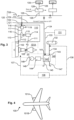
- a first example aircraft 100 of the invention comprises first and second turbofan engines 101A, 101B, a cabin blower system 110, a ducting system 120, an air-conditioning system 128, a cabin 130, a hydrogen fuel tank 132 and a fuel cell system 140 comprising a polymer-electrolyte (proton-exchange) membrane (PEM) fuel cell stack 142 having one or more individual PEM fuel cells.
- the first turbofan engine 101A comprises a fan case 102 and an engine shaft 105.
- the cabin blower system 110 comprises a cabin blower compressor 116 (a centrifugal compressor) and a transmission system 114 having input and output shafts 111, 115 engaged with the engine shaft 105 and the cabin blower compressor 116 respectively.
- compressed air output from the cabin blower compressor 116 is delivered to a system output 119 of the cabin blower system 110 via a duct 117 which passes through a heat-exchanger 118.
- the cabin blower compressor 116 and the heat-exchanger 118 are supplied with fan delivery air via ducts 112, 113 respectively which are connected to the fan case 102.
- the heat-exchanger 118 cools the compressed air output by the cabin blower compressor 116 prior to its delivery to the system output 119.
- the transmission 114 may comprise discrete gears or it may be continuously-variable transmission (CVT).
- the transmission 114 may be of a type described in patents EP 3034405 B1 or EP 3517436 B1 (i.e.
- the transmission 114 allows the speed of the compressor 116 to be controlled independently or substantially independently of the speed of the engine shaft 105.
- the cabin blower compressor 116 and/or the heat-exchanger 118 are supplied with bypass air of the turbofan engine 101A or with ram air of the aircraft 100.
- the ducting system 120 comprises a first duct 121 coupling the system output 119 of the cabin blower system 110 to an input of a regulator valve 122 and second and third ducts 124, 126 coupling first and second outputs of the regulator valve 122 to the fuel cell system 140 and to a cabin 130 of the aircraft 100, via an air-conditioning system 128, respectively.
- the regulator valve 122 allows the proportions of the mass flow rate of compressed air output by the cabin blower compressor 116 which are provided to the fuel cell system 140 and to the air-conditioning system 128 (or to the air-conditioning system 128 and parts of the aircraft 100 requiring de-icing) to be adjusted.
- the duct 124 delivers compressed air to the cathode input 141 of the PEM fuel cell stack 142.
- Hydrogen fuel is provided to the anode input 143 of the PEM fuel cell stack 142 from the hydrogen fuel tank 132 via a duct 134.
- the fuel cell system 140 further comprises an electric motor 146 arranged to receive electrical power output by the PEM fuel cell stack 142 via a power management system 144 and to provide mechanical power to the engine shaft 105 via an output shaft 148 of the electric motor 146, the output shaft 148 being mechanically engaged with the engine shaft 105.
- the mass flow rate of compressed air, output by the cabin blower compressor 116, in excess of that required for ventilation of the cabin 130 is provided to the cathode input 144 of the PEM fuel cell stack 142.
- the fuel cell system 140 allows power associated with the excess capacity of the cabin blower compressor 216 to be recovered and provided to the turbofan engine 101A, thus mitigating, and possibly eliminating, the fuel consumption penalty on the turbofan engine 101A corresponding to the excess capacity.
- the PEM fuel cell stack 142 has cathode and anode exhausts 145, 147; cathode exhaust (i.e. hot air and water vapour) may be used for functions such as de-icing, ice protection, fuel heating and oil heating within the aircraft 100.
- the pressure of compressed air delivered to the cathode input 141 of the PEM fuel cell stack 142 is typically sufficient to allow high-efficiency operation of the PEM fuel cell stack 142, for example much higher efficiency than that achievable using ram air.
- the regulator valve 122 allows the proportion of the mass flow rate of compressed air output by the cabin blower system 110 at the system output 119 and delivered to the cathode input 141 of the PEM fuel cell stack 142 to be varied continuously. That proportion may be zero percent if the whole of the mass flow rate of compressed air output by the cabin blower system 110 is required for ventilation of the cabin 130, or for cabin ventilation and de-icing, for example during critical flight conditions. In that case, the cabin blower compressor 116 operates with high efficiency at or close to its design point, and since the full capacity of the cabin blower system 110 is utilised, the cabin blower compressor 116 has no excess capacity and there is no corresponding fuel consumption penalty on the turbofan engine 101A.
- the fuel cell system 140 may continue to operate if apparatus 131 is present which can provide compressed air to the cathode input 141 of the PEM fuel cell stack 142 via a duct 133 independently of the cabin blower system 110.
- the apparatus 131 could be a source of ram air or compressor bleed air or bypass air from either or both turbofan engines 201A, 201B. If the apparatus 131 is operable to provide compressed air to the cathode input 141 of the PEM fuel cell stack 142 when the aircraft 100 is stationary on the ground, then the fuel cell system 140 may be used to start the turbofan engine 201A; for example the apparatus 131 may be a small, independently-powered compressor.
- the motor output shaft 148 or the PEM fuel cell stack 142 may be respectively mechanically or electrically disconnectable from the engine shaft 105 or the power management system 144 so that mechanical or electrical power may be delivered to an auxiliary system of the aircraft 100, such as a hydraulic system, pumps, controllers, instrumentation, navigation system etc.
- the power associated with the excess capacity of the cabin blower system 110 may thus be directed to an auxiliary function, rather than being recovered to the turbofan engine 101A.
- the fuel cell system 140 may be applied to the auxiliary function during a part or parts of a flight cycle and used to recover power to the turbofan engine 101A during remaining parts of the flight cycle.
- the fuel cell system 140 may be comprised in the aircraft 100 principally to power one or more auxiliary systems, the arrangement of Figure 3 being put into effect when it is not required to power an auxiliary system, thus making use of the fuel cell system 140 when it would otherwise be idle and thus simply parasitic weight. If the apparatus 131 is present, the fuel cell system 140 may be utilised, even if the regulator valve 122 is adjusted so that 100% of the mass flow rate of compressed air output by the cabin blower system 110 is directed to the air-conditioning system 128 (and then to the cabin 130), or to the air-conditioning system 128 and parts of the aircraft requiring de-icing or ice protection.
- the engine shaft 105 with which the transmission input shaft 111 and the motor output shaft 148 are engaged may be the high- or low-pressure shaft of the turbofan engine 101A where the engine 101A is a two-spool engine. If the turbofan engine 101A is a three-spool engine, the shaft 105 may be a high-, low- or intermediate-pressure shaft of the engine 101A. In a variant of the aircraft 100, the motor output shaft 148 and the transmission input shaft 111 may be coupled to different shafts of the turbofan engine 101A, thus allowing power to be transferred between shafts.
- the transmission input shaft 111 may be engaged with the low-pressure shaft of the turbofan engine 101A and the motor output shaft 148 may be engaged with the high-pressure shaft of the turbofan engine 101A.
- the transmission input shaft 111 may be engaged with or coupled to the low-, intermediate- or high-pressure shaft of the turbofan engine 101A and the motor output shaft 148 may be engaged with or coupled to one of the other two shafts of the turbofan engine 101A.
- the work split between the shafts may be controlled, improving engine operability and time-on-wing.
- the cabin blower compressor 116 runs at or near its maximum capacity, and hence at or near maximum efficiency, for most of an operational period of the aircraft 100.
- the transmission 114 therefore needs to provide less speed variation than the transmission 14 in an aircraft of the prior art which comprises the arrangement of Figure 1 , allowing the transmission 114 to have lower size and weight.
- the turbofan engines 101A, 101B may be hydrogen-burning turbofan engines, the aircraft 100 further including a hydrogen fuel store 136 and conveying means 137 for delivering hydrogen fuel from the hydrogen fuel store 136.
- hydrogen fuel may also be provided to the anode input 143 of the PEM fuel cell stack 142 from the hydrogen fuel tank 136 via conveying means 138 and the hydrogen fuel store 132 dispensed with.
- gaseous hydrogen resulting from venting of the hydrogen fuel tank 136, or boil-off from the liquid hydrogen stored therein, may be used to supply the PEM fuel cell stack 142, rather than being wasted, as would be the case in the prior art arrangements of Figures 1 and 2 where the turbofan engines 1, 51 are hydrogen-burning engines.
- the fuel cell stack 142 may be of a type other than a PEM or high-temperature PEM fuel cell stack, provided one of its inputs may use compressed air from the cabin blower compressor 116.
- the hydrogen fuel store 132 may store gaseous or liquid hydrogen. If the hydrogen fuel store 132 stores liquid hydrogen, further apparatus may be required to vaporise stored liquid hydrogen prior to its input to the anode input 143 of the PEM fuel cell stack 142. Similarly, if the turbofan engine 101A is a hydrogen-burning engine, further apparatus may be required to vaporised liquid hydrogen store in the hydrogen fuel store 136 prior to its input to the combustor of the turbofan engine 101A.
- a second example aircraft 200 of the invention comprises turbofan engines 201A, 201B, a cabin blower system 210, a ducting system 220 and a cabin 230.
- Output shaft 248 of electric motor 246, which is comprised in fuel cell system 240, is either engaged with the input of transmission system 214 together with transmission input shaft 211, or with the output of the transmission system 214, in which case the motor output shaft 248 may be directly coupled to transmission output shaft 215.
- the arrangement of Figure 5 operates similarly to the arrangement of Figure 3 , except that power associated with the excess capacity of cabin blower compressor 216 is recovered to the cabin blower compressor 216 itself, rather than to turbofan engine 201A, in order to mitigate or eliminate the fuel consumption penalty on the turbofan engine 201A associated with the excess capacity.
- input shaft 211 may be disengaged with engine shaft 204 such that cabin blower compressor 216 is power entirely by fuel cell system 240.
- the fuel cell system 240 may provide mechanical power to both cabin blower system 210 and to turbofan engine 201A.
- a third example aircraft 300 of the invention comprises turbofan engines 301A, 301B, a cabin blower system 310, a ducting system 320, a fuel cell system 340 and a boundary-layer ingestion (BLI) propulsion system 399 which comprises a BLI fan 349.
- the fuel cell system 340 provides mechanical power to the BLI fan 349. Power associated with the excess capacity of the cabin blower system 310 is thus applied to driving the BLI fan, rather than being recovered to either the turbofan engine 301A or to cabin blower compressor 316.
- Additional fuel consumption of the turbofan engine 301A associated with excess capacity of the cabin blower compressor 316 is thus usefully employed in driving the BLI fan 349, rather than being wasted, as in the prior art, or used to mitigate or eliminate a fuel consumption penalty on the turbofan engine 301A, as in the case of the arrangements of Figures 3 and 5 .
- Figure 9 shows a flowchart illustrating steps in a method 400 of providing compressed air to the cathode input of a fuel cell stack comprised in an aircraft.
- compressed air is generated 404 using a cabin blower system (CBS) of the aircraft.
- a portion of the mass flow rate of compressed air output by the cabin blower system is provided 406 to the cathode input of the fuel cell stack.
- Electrical power generated by the fuel cell stack is provided 408 to an electric motor.
- Mechanical power from the electric motor is provided 410 to a shaft of an internal combustion engine (such as a gas turbine engine), a portion of the mechanical output power of which is provided to the cabin blower system in order to drive it.
- the method ends 412.
Landscapes
- Engineering & Computer Science (AREA)
- Aviation & Aerospace Engineering (AREA)
- Mechanical Engineering (AREA)
- General Engineering & Computer Science (AREA)
- Health & Medical Sciences (AREA)
- General Health & Medical Sciences (AREA)
- Pulmonology (AREA)
- Chemical & Material Sciences (AREA)
- Combustion & Propulsion (AREA)
- Fuel Cell (AREA)
Abstract
Description
- The invention relates to aircraft comprising cabin blower systems and to uses of cabin blower systems.
- A cabin blower system is a system which provides ventilation air to a cabin space of an aircraft. A cabin blower system typically forms part of an environmental control system which provides air at appropriate temperature and pressure to a passenger cabin, cockpit or similar cabin space. A cabin blower system of an aircraft may also provide air for further functions, such as wing or engine cowl de-icing or ice protection.
-
Figure 1 schematically shows apparatus comprised in an aircraft of the prior art, the apparatus comprising aturbofan engine 1, acabin blower system 10, aducting system 20, an air-conditioning system 28 and acabin 30. Thecabin blower system 10 comprises acabin blower compressor 16 driven by mechanical power derived from theturbofan engine 1 via an off-take shaft or dedicatedradial drive 11 engaged with a shaft 5 of theturbofan engine 1 and atransmission 14 having anoutput shaft 15 coupled to thecabin blower compressor 16. The shaft 5 may be a high- or low-pressure shaft if theturbofan engine 1 is a two-spool engine; alternatively the off-take 11 may be engaged with both high- and low-pressure shafts. Theturbofan engine 1 has afan case 2, acompressor section 3, aturbine section 4 and a combustor section (not shown inFigure 1 in the interests of clarity). Fan delivery air is provided from thefan case 2 to thecabin blower compressor 16 via aduct 12. (Alternatively, bypass air, ram air or bleed air from early stages of thecompressor section 3 may be input to the cabin blower compressor 16). Compressed air output by thecabin blower compressor 16 passes to aheat exchanger 18 via aduct 17 which passes through theheat exchanger 18. The heat-exchanger 18 is arranged to receive fan delivery air from thefan case 2 via aduct 13. Cooled compressed air is provided to anoutput 19 of thecabin blower system 10 and thence to ducting 20 for onward delivery to thecabin 30 via the air-conditioning system 28, and/or to aircraft parts requiring de-icing or ice protection. Thetransmission 14 allows the speed of thecabin blower compressor 16 to be controlled independently or substantially independently of the speed of the shaft 5. -
Figure 2 , in which parts are labelled with reference signs differing by 50 from those labelling corresponding parts inFigure 1 , shows other aircraft apparatus of the prior art. Mechanical power from ashaft 55 of aturbofan engine 51 is provided via aradial drive 61 to anelectrical generator 64A which provides electrical power to anelectric motor 64B. Themotor 64B provides mechanical power to acabin blower compressor 66 via an output shaft 5 of themotor 64B. - A significant disadvantage associated with a cabin blower system of the prior art, such as the
system 10 ofFigure 1 or thesystem 60 ofFigure 2 , is that it is over-sized for the majority of nominal operating conditions, i.e. it produces a greater mass flow rate of compressed air than is typically required during a flight cycle. In other words the cabin blower system has excess capacity, resulting in a fuel consumption penalty on an engine driving the system. The (normally) excess capacity must however be available in order to meet failure requirements and critical flight conditions which may arise, such as operation in an ice environment and during engine idling. However, operating the cabin blower compressor at a lower capacity penalises the compressor's stability and reduces its efficiency and so does not provide a satisfactory solution to the problem of the fuel consumption penalty. Such operation may not even be possible since the transmission via which a cabin blower compressor is driven may preclude operation of the cabin blower compressor at a speed below that consistent with a minimum level of efficiency. If the transmission is capable of a speed ratio which does allow such operation, it is likely to be of substantial size and to represent a further weight penalty to an aircraft comprising the cabin blower system. - A first aspect of the invention provides an aircraft comprising:
- an internal combustion engine,
- a cabin blower system comprising a cabin blower compressor and a drive arrangement engaged with the internal combustion engine and arranged to transmit mechanical power from the internal combustion engine to the cabin blower compressor;
- a fuel cell stack comprising at least one fuel cell; and
- a ducting system arranged to deliver respective portions of the mass flow rate of compressed air output by the cabin blower compressor to:
- (a) a cabin space of the aircraft; and
- (b) the cathode input of the fuel cell stack.
- In operation of the aircraft, a portion of the mass flow rate of compressed air output by the cabin blower compressor which is in excess of that required for ventilation of the cabin space is provided to the cathode input of the fuel cell stack. The fuel consumption penalty on the engine corresponding to the excess mass flow rate is at least partially recovered or compensated for by electrical power output from the fuel cell stack.
- The aircraft may further comprise an electric motor arranged to receive electrical power from the fuel cell stack, the electric motor being engaged with a shaft of the internal combustion engine and arranged to provide mechanical power to the shaft of the internal combustion engine. By recovering mechanical power back to the engine, the fuel consumption penalty on the engine is mitigated or eliminated.
- The drive arrangement may comprise a transmission system having an output shaft coupled to the cabin blower compressor and an input shaft engaged with a shaft of the internal combustion engine. The range of speed variation required of the transmission is less than that required of cabin blower system of the prior art, allowing a transmission of smaller physical size and lower weight to be used.
- The internal combustion engine may be a gas turbine engine, the input of the transmission system and the electric motor being engaged with a common shaft of the gas turbine engine. Alternatively, the input shaft of the transmission system may be engaged with a first shaft of the gas turbine engine and the electric motor may be engaged with a second shaft of the gas turbine engine, allowing power to be transferred from the first shaft to the second shaft.
- Instead of the electric motor being engaged with a shaft of the internal combustion engine and arranged to provide mechanical power to the shaft of the internal combustion engine, the electric motor may be engaged with the drive arrangement and arranged to provide mechanical power to the cabin blower compressor via the drive arrangement. The fuel consumption penalty on the engine corresponding to the excess mass flow rate output by the cabin blower compressor is mitigated or eliminated. In this case, the drive arrangement may comprise a transmission system having an output shaft coupled to the cabin blower compressor and an input shaft engaged with a shaft of the internal combustion engine, the electric motor being engaged with either the input shaft or the output shaft of the transmission system.
- In a further alternative, the electric motor is arranged to provide mechanical power to a fan comprised in a boundary-layer ingestion propulsion arrangement of the aircraft. The fuel consumption penalty on the engine corresponding to the excess mass flow rate of compressed air output by the cabin blower compressor is thus usefully employed in assisting propulsion of the aircraft.
- The ducting system may comprise a regulator valve, a first duct coupling the output of the cabin blower system to an input of the regulator valve, a second duct coupling a first output of the regulator valve to the cathode input of the fuel cell stack and a third duct coupling a second output of the regulator valve to the cabin space of the aircraft, the regulator valve being operable to control respective proportions of the mass flow rate of compressed air output by the cabin blower system which are delivered to the cabin space and to the cathode input of the fuel cell stack.
- The aircraft may further comprise apparatus operable to provide compressed air to the cathode input of the fuel cell stack independently of the cabin blower compressor. Thus, if 100% of the mass flow rate of compressed air output by the cabin blower compressor is directed to the cabin, the fuel cell stack may nevertheless be operated.
- The internal combustion engine may be a hydrogen-burning engine, the aircraft further comprising a fuel tank of liquid hydrogen and conveying means arranged to deliver hydrogen fuel from the fuel tank to the internal combustion engine and boiled-off and/or vented gaseous hydrogen from the fuel tank to the anode input of the fuel cell stack.
- According to a second aspect of the invention, a cabin blower system or cabin blower compressor is used to provide compressed air to the cathode input of a fuel cell stack.
- According to a third aspect of the invention, a method of providing compressed air to the cathode input of a fuel cell stack comprised in an aircraft comprises the step of applying a portion of the mass flow rate of compressed air output by a cabin blower system or cabin blower compressor of the aircraft to the cathode input of the fuel cell stack. The method may further comprise the steps of providing electrical power from the fuel cell stack to an electric motor to generate mechanical power and providing the mechanical power to either (a) the cabin blower system, or as the case may be, to the cabin blower compressor, or (b) to a shaft of an internal combustion engine arranged to drive the cabin blower system, or as the case may be, the cabin blower compressor.
- Embodiments of the invention are described below by way of example only and with reference to the accompanying drawings in which:
- Figures 3, 5 & 7
- show first, second and third examples of aircraft apparatus of the invention, respectively;
- Figures 4, 6 & 8
- show first, second and third example aircraft of the invention respectively, comprising the aircraft apparatus of
Figures 3 ,5 &7 respectively; and - Figure 9
- shows steps in an example method for providing compressed air to the cathode input of a fuel cell stack.
- Referring to
Figures 3 and 4 , afirst example aircraft 100 of the invention comprises first andsecond turbofan engines cabin blower system 110, aducting system 120, an air-conditioning system 128, acabin 130, ahydrogen fuel tank 132 and afuel cell system 140 comprising a polymer-electrolyte (proton-exchange) membrane (PEM)fuel cell stack 142 having one or more individual PEM fuel cells. Thefirst turbofan engine 101A comprises afan case 102 and anengine shaft 105. Thecabin blower system 110 comprises a cabin blower compressor 116 (a centrifugal compressor) and atransmission system 114 having input andoutput shafts engine shaft 105 and thecabin blower compressor 116 respectively. - In operation of the
aircraft 100, compressed air output from thecabin blower compressor 116 is delivered to asystem output 119 of thecabin blower system 110 via aduct 117 which passes through a heat-exchanger 118. Thecabin blower compressor 116 and the heat-exchanger 118 are supplied with fan delivery air viaducts fan case 102. The heat-exchanger 118 cools the compressed air output by thecabin blower compressor 116 prior to its delivery to thesystem output 119. Thetransmission 114 may comprise discrete gears or it may be continuously-variable transmission (CVT). Thetransmission 114 may be of a type described in patentsEP 3034405 B1 orEP 3517436 B1 (i.e. including a mechanical or electrical variator). Thetransmission 114 allows the speed of thecompressor 116 to be controlled independently or substantially independently of the speed of theengine shaft 105. In variants of theaircraft 100, thecabin blower compressor 116 and/or the heat-exchanger 118 are supplied with bypass air of theturbofan engine 101A or with ram air of theaircraft 100. - The
ducting system 120 comprises afirst duct 121 coupling thesystem output 119 of thecabin blower system 110 to an input of aregulator valve 122 and second andthird ducts regulator valve 122 to thefuel cell system 140 and to acabin 130 of theaircraft 100, via an air-conditioning system 128, respectively. Theregulator valve 122 allows the proportions of the mass flow rate of compressed air output by thecabin blower compressor 116 which are provided to thefuel cell system 140 and to the air-conditioning system 128 (or to the air-conditioning system 128 and parts of theaircraft 100 requiring de-icing) to be adjusted. Theduct 124 delivers compressed air to thecathode input 141 of the PEMfuel cell stack 142. Hydrogen fuel is provided to theanode input 143 of the PEMfuel cell stack 142 from thehydrogen fuel tank 132 via aduct 134. Thefuel cell system 140 further comprises anelectric motor 146 arranged to receive electrical power output by the PEMfuel cell stack 142 via apower management system 144 and to provide mechanical power to theengine shaft 105 via anoutput shaft 148 of theelectric motor 146, theoutput shaft 148 being mechanically engaged with theengine shaft 105. - In operation of the
aircraft 100, the mass flow rate of compressed air, output by thecabin blower compressor 116, in excess of that required for ventilation of thecabin 130 is provided to thecathode input 144 of the PEMfuel cell stack 142. Thefuel cell system 140 allows power associated with the excess capacity of thecabin blower compressor 216 to be recovered and provided to theturbofan engine 101A, thus mitigating, and possibly eliminating, the fuel consumption penalty on theturbofan engine 101A corresponding to the excess capacity. The PEMfuel cell stack 142 has cathode and anode exhausts 145, 147; cathode exhaust (i.e. hot air and water vapour) may be used for functions such as de-icing, ice protection, fuel heating and oil heating within theaircraft 100. The pressure of compressed air delivered to thecathode input 141 of the PEMfuel cell stack 142 is typically sufficient to allow high-efficiency operation of the PEMfuel cell stack 142, for example much higher efficiency than that achievable using ram air. - The
regulator valve 122 allows the proportion of the mass flow rate of compressed air output by thecabin blower system 110 at thesystem output 119 and delivered to thecathode input 141 of the PEMfuel cell stack 142 to be varied continuously. That proportion may be zero percent if the whole of the mass flow rate of compressed air output by thecabin blower system 110 is required for ventilation of thecabin 130, or for cabin ventilation and de-icing, for example during critical flight conditions. In that case, thecabin blower compressor 116 operates with high efficiency at or close to its design point, and since the full capacity of thecabin blower system 110 is utilised, thecabin blower compressor 116 has no excess capacity and there is no corresponding fuel consumption penalty on theturbofan engine 101A. Nevertheless thefuel cell system 140 may continue to operate ifapparatus 131 is present which can provide compressed air to thecathode input 141 of the PEMfuel cell stack 142 via aduct 133 independently of thecabin blower system 110. Theapparatus 131 could be a source of ram air or compressor bleed air or bypass air from either or bothturbofan engines apparatus 131 is operable to provide compressed air to thecathode input 141 of the PEMfuel cell stack 142 when theaircraft 100 is stationary on the ground, then thefuel cell system 140 may be used to start theturbofan engine 201A; for example theapparatus 131 may be a small, independently-powered compressor. - Whether or not the
apparatus 131 is present, themotor output shaft 148 or the PEMfuel cell stack 142 may be respectively mechanically or electrically disconnectable from theengine shaft 105 or thepower management system 144 so that mechanical or electrical power may be delivered to an auxiliary system of theaircraft 100, such as a hydraulic system, pumps, controllers, instrumentation, navigation system etc. The power associated with the excess capacity of thecabin blower system 110 may thus be directed to an auxiliary function, rather than being recovered to theturbofan engine 101A. Thefuel cell system 140 may be applied to the auxiliary function during a part or parts of a flight cycle and used to recover power to theturbofan engine 101A during remaining parts of the flight cycle. Thefuel cell system 140 may be comprised in theaircraft 100 principally to power one or more auxiliary systems, the arrangement ofFigure 3 being put into effect when it is not required to power an auxiliary system, thus making use of thefuel cell system 140 when it would otherwise be idle and thus simply parasitic weight. If theapparatus 131 is present, thefuel cell system 140 may be utilised, even if theregulator valve 122 is adjusted so that 100% of the mass flow rate of compressed air output by thecabin blower system 110 is directed to the air-conditioning system 128 (and then to the cabin 130), or to the air-conditioning system 128 and parts of the aircraft requiring de-icing or ice protection. - The
engine shaft 105 with which thetransmission input shaft 111 and themotor output shaft 148 are engaged may be the high- or low-pressure shaft of theturbofan engine 101A where theengine 101A is a two-spool engine. If theturbofan engine 101A is a three-spool engine, theshaft 105 may be a high-, low- or intermediate-pressure shaft of theengine 101A. In a variant of theaircraft 100, themotor output shaft 148 and thetransmission input shaft 111 may be coupled to different shafts of theturbofan engine 101A, thus allowing power to be transferred between shafts. For example, if theturbofan engine 101A has two spools, thetransmission input shaft 111 may be engaged with the low-pressure shaft of theturbofan engine 101A and themotor output shaft 148 may be engaged with the high-pressure shaft of theturbofan engine 101A. - If the
turbofan engine 101A has three spools, thetransmission input shaft 111 may be engaged with or coupled to the low-, intermediate- or high-pressure shaft of theturbofan engine 101A and themotor output shaft 148 may be engaged with or coupled to one of the other two shafts of theturbofan engine 101A. By making appropriate choices for the engine shafts with which thetransmission input shaft 111 and themotor output shaft 148 are engaged, the work split between the shafts may be controlled, improving engine operability and time-on-wing. - The
cabin blower compressor 116 runs at or near its maximum capacity, and hence at or near maximum efficiency, for most of an operational period of theaircraft 100. Thetransmission 114 therefore needs to provide less speed variation than thetransmission 14 in an aircraft of the prior art which comprises the arrangement ofFigure 1 , allowing thetransmission 114 to have lower size and weight. - The
turbofan engines aircraft 100 further including ahydrogen fuel store 136 and conveyingmeans 137 for delivering hydrogen fuel from thehydrogen fuel store 136. In this case, hydrogen fuel may also be provided to theanode input 143 of the PEMfuel cell stack 142 from thehydrogen fuel tank 136 via conveyingmeans 138 and thehydrogen fuel store 132 dispensed with. If thehydrogen fuel store 136 stores liquid hydrogen, then gaseous hydrogen resulting from venting of thehydrogen fuel tank 136, or boil-off from the liquid hydrogen stored therein, may be used to supply the PEMfuel cell stack 142, rather than being wasted, as would be the case in the prior art arrangements ofFigures 1 and 2 where theturbofan engines - In variants of the
aircraft 100, thefuel cell stack 142 may be of a type other than a PEM or high-temperature PEM fuel cell stack, provided one of its inputs may use compressed air from thecabin blower compressor 116. Thehydrogen fuel store 132 may store gaseous or liquid hydrogen. If thehydrogen fuel store 132 stores liquid hydrogen, further apparatus may be required to vaporise stored liquid hydrogen prior to its input to theanode input 143 of the PEMfuel cell stack 142. Similarly, if theturbofan engine 101A is a hydrogen-burning engine, further apparatus may be required to vaporised liquid hydrogen store in thehydrogen fuel store 136 prior to its input to the combustor of theturbofan engine 101A. - Referring to
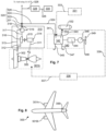
Figures 5 and 6 , in which parts are labelled with reference numerals differing by 100 from those labelling corresponding parts inFigures 3 and 4 , asecond example aircraft 200 of the invention comprisesturbofan engines cabin blower system 210, a ducting system 220 and acabin 230.Output shaft 248 ofelectric motor 246, which is comprised infuel cell system 240, is either engaged with the input oftransmission system 214 together withtransmission input shaft 211, or with the output of thetransmission system 214, in which case themotor output shaft 248 may be directly coupled totransmission output shaft 215. - The arrangement of
Figure 5 operates similarly to the arrangement ofFigure 3 , except that power associated with the excess capacity ofcabin blower compressor 216 is recovered to thecabin blower compressor 216 itself, rather than toturbofan engine 201A, in order to mitigate or eliminate the fuel consumption penalty on theturbofan engine 201A associated with the excess capacity. - During descent of the
aircraft 200 from cruise conditions,input shaft 211 may be disengaged with engine shaft 204 such thatcabin blower compressor 216 is power entirely byfuel cell system 240. Alternatively, thefuel cell system 240 may provide mechanical power to bothcabin blower system 210 and to turbofanengine 201A. - Referring to
Figures 7 and 8 , in which parts are labelled with reference numerals differing by 200 from those labelling corresponding parts inFigures 3 and 4 , athird example aircraft 300 of the invention comprisesturbofan engines cabin blower system 310, aducting system 320, afuel cell system 340 and a boundary-layer ingestion (BLI)propulsion system 399 which comprises aBLI fan 349. In operation of theaircraft 300, thefuel cell system 340 provides mechanical power to theBLI fan 349. Power associated with the excess capacity of thecabin blower system 310 is thus applied to driving the BLI fan, rather than being recovered to either theturbofan engine 301A or tocabin blower compressor 316. Additional fuel consumption of theturbofan engine 301A associated with excess capacity of thecabin blower compressor 316 is thus usefully employed in driving theBLI fan 349, rather than being wasted, as in the prior art, or used to mitigate or eliminate a fuel consumption penalty on theturbofan engine 301A, as in the case of the arrangements ofFigures 3 and5 . -
Figure 9 shows a flowchart illustrating steps in amethod 400 of providing compressed air to the cathode input of a fuel cell stack comprised in an aircraft. Following starting 402 of the method, compressed air is generated 404 using a cabin blower system (CBS) of the aircraft. A portion of the mass flow rate of compressed air output by the cabin blower system is provided 406 to the cathode input of the fuel cell stack. Electrical power generated by the fuel cell stack is provided 408 to an electric motor. Mechanical power from the electric motor is provided 410 to a shaft of an internal combustion engine (such as a gas turbine engine), a portion of the mechanical output power of which is provided to the cabin blower system in order to drive it. The method then ends 412.
Claims (15)
- An aircraft (100; 200; 300) comprising:an internal combustion engine (101A; 201A; 301A);a cabin blower system (110; 210; 310) comprising a cabin blower compressor (116; 216; 316) and a drive arrangement (111, 114, 115; 211, 214, 215; 311, 314, 315) engaged with the internal combustion engine and arranged to transmit mechanical power from the internal combustion engine to the cabin blower compressor;a fuel cell stack (142; 242; 342) comprising at least one fuel cell; anda ducting system (120; 220; 320) arranged to deliver respective portions of the mass flow rate of compressed air output by the cabin blower compressor to:(a) a cabin space (130; 230; 330) of the aircraft; and(b) the cathode input (141; 241; 341) of the fuel cell stack.
- An aircraft (100) according to claim 1 further comprising an electric motor (146) arranged to receive electrical power from the fuel cell stack, the electric motor being engaged with a shaft of the internal combustion engine and arranged to provide mechanical power to the shaft of the internal combustion engine.
- An aircraft (100) according to claim 2 wherein the drive arrangement comprises a transmission system (114) having an output shaft (115) coupled to the cabin blower compressor and an input shaft (111) engaged with a shaft of the internal combustion engine.
- An aircraft (100) according to claim 3 wherein the internal combustion engine is a gas turbine engine, and the input of the transmission system and the electric motor are engaged with a common shaft (105) of the gas turbine engine.
- An aircraft (100) according to claim 3 wherein the internal combustion engine is a gas turbine engine, the input shaft of the transmission system is engaged with a first shaft of the gas turbine engine and the electric motor is engaged with a second shaft of the gas turbine engine.
- An aircraft (200) according to claim 1 further comprising an electric motor (246) arranged to receive electrical power from the fuel cell stack, wherein the electric motor is engaged with the drive arrangement and arranged to provide mechanical power to the cabin blower compressor via the drive arrangement.
- An aircraft (200) according to claim 6 wherein the drive arrangement comprises a transmission system having an output shaft (215) coupled to the cabin blower compressor and an input shaft (211) engaged with a shaft (205) of the internal combustion engine and wherein the electric motor is engaged with either the input shaft or the output shaft of the transmission system.
- An aircraft (300) according to claim 1 and further comprising an electric motor arranged to receive electrical power from the fuel cell stack and provide mechanical power to a fan (349) comprised in a boundary-layer ingestion propulsion arrangement (399) of the aircraft.
- An aircraft (100; 200; 300) according to any preceding claim wherein the ducting system comprises a regulator valve (122; 222; 322), a first duct (121; 221; 321) coupling the output (119; 219; 319) of the cabin blower system to an input of the regulator valve, a second duct (124; 224; 324) coupling a first output of the regulator valve to the cathode input of the fuel cell stack and a third duct (126; 226; 326) coupling a second output of the regulator valve to the cabin space of the aircraft, wherein the regulator valve is operable to control respective proportions of the mass flow rate of compressed air output by the cabin blower system which are delivered to the cabin space and to the cathode input of the fuel cell stack.
- An aircraft (100; 200; 300) according to any preceding claim further comprising apparatus (131, 133; 231, 233; 331, 333) operable to provide compressed air to the cathode input of the fuel cell stack independently of the cabin blower compressor.
- An aircraft (100; 200; 300) according to any preceding claim wherein the internal combustion engine is a hydrogen-burning engine and the aircraft further comprises a fuel tank (132; 232; 332) of liquid hydrogen and conveying means (137, 138; 237, 238; 337, 338) arranged to deliver hydrogen fuel from the fuel tank to the internal combustion engine and boiled-off and/or vented gaseous hydrogen from the fuel tank to the anode input (143; 243; 343) of the fuel cell stack.
- Use of a cabin blower system or a cabin blower compressor to provide compressed air to the cathode input of a fuel cell stack.
- A method (400) of providing compressed air to the cathode input of a fuel cell stack comprised in an aircraft, the method comprising the step of applying (406) a portion of the mass flow rate of compressed air output by a cabin blower system or cabin blower compressor of the aircraft to the cathode input of the fuel cell stack.
- A method according to claim 13 further comprising the steps of:(i) providing (408) electrical power from the fuel cell stack to an electric motor to generate mechanical power; and(ii) providing (410) the mechanical power to the cabin blower system, or as the case may be to the cabin blower compressor.
- A method according to claim 13 further comprising the steps of:(i) providing (408) electrical power from the fuel cell stack to an electric motor to generate mechanical power; and(ii) providing (410) the mechanical power to a shaft of an internal combustion engine arranged to drive the cabin blower system, or as the case be, the cabin blower compressor.
Applications Claiming Priority (1)
| Application Number | Priority Date | Filing Date | Title |
|---|---|---|---|
| GR20230100523 | 2023-06-28 |
Publications (2)
| Publication Number | Publication Date |
|---|---|
| EP4484289A1 true EP4484289A1 (en) | 2025-01-01 |
| EP4484289B1 EP4484289B1 (en) | 2025-12-10 |
Family
ID=88017073
Family Applications (1)
| Application Number | Title | Priority Date | Filing Date |
|---|---|---|---|
| EP24176285.5A Active EP4484289B1 (en) | 2023-06-28 | 2024-05-16 | Aircraft comprising a cabin blower system |
Country Status (3)
| Country | Link |
|---|---|
| US (1) | US20250002160A1 (en) |
| EP (1) | EP4484289B1 (en) |
| GB (1) | GB202312177D0 (en) |
Citations (4)
| Publication number | Priority date | Publication date | Assignee | Title |
|---|---|---|---|---|
| EP1035016A1 (en) * | 1999-03-12 | 2000-09-13 | DaimlerChrysler AG | Auxiliary Power Unit for Aircraft |
| US8640439B2 (en) * | 2006-11-29 | 2014-02-04 | Airbus Operations Gmbh | Hybrid drive for an aircraft |
| EP3034405B1 (en) | 2014-12-11 | 2019-01-09 | Rolls-Royce plc | Cabin blower system |
| EP3517436B1 (en) | 2018-01-26 | 2020-05-27 | Rolls-Royce plc | Cabin blower system |
-
2023
- 2023-08-09 GB GBGB2312177.5A patent/GB202312177D0/en not_active Ceased
-
2024
- 2024-05-16 EP EP24176285.5A patent/EP4484289B1/en active Active
- 2024-06-26 US US18/754,879 patent/US20250002160A1/en active Pending
Patent Citations (4)
| Publication number | Priority date | Publication date | Assignee | Title |
|---|---|---|---|---|
| EP1035016A1 (en) * | 1999-03-12 | 2000-09-13 | DaimlerChrysler AG | Auxiliary Power Unit for Aircraft |
| US8640439B2 (en) * | 2006-11-29 | 2014-02-04 | Airbus Operations Gmbh | Hybrid drive for an aircraft |
| EP3034405B1 (en) | 2014-12-11 | 2019-01-09 | Rolls-Royce plc | Cabin blower system |
| EP3517436B1 (en) | 2018-01-26 | 2020-05-27 | Rolls-Royce plc | Cabin blower system |
Also Published As
| Publication number | Publication date |
|---|---|
| US20250002160A1 (en) | 2025-01-02 |
| EP4484289B1 (en) | 2025-12-10 |
| GB202312177D0 (en) | 2023-09-20 |
Similar Documents
| Publication | Publication Date | Title |
|---|---|---|
| EP4261961B1 (en) | Hydrogen-fuelled aircraft power system | |
| EP4174304A1 (en) | Aircraft propulsion system | |
| EP4227512A1 (en) | Hydrogen-oxygen fueled powerplant with water and heat recovery | |
| EP3517436B1 (en) | Cabin blower system | |
| US7624592B2 (en) | Flexible power and thermal architectures using a common machine | |
| EP2584173B1 (en) | Gas Turbine Engine | |
| US8117827B2 (en) | Apparatus for operating gas turbine engines | |
| EP1574689B1 (en) | Methods and apparatus for operating gas turbine engines | |
| US12479591B2 (en) | System for conditioning fuel for supplying an aircraft turbomachine, aircraft and method of use | |
| EP4224000B1 (en) | Multiple turboexpander system having selective coupler | |
| EP1728990A2 (en) | Auxiliary power unit supplied with air from the gas turbine | |
| US20110302903A1 (en) | Lubrication driven gas turbine engine actuation system | |
| US12270341B2 (en) | Gas turbine engine fuel system | |
| WO1991004395A2 (en) | Integrated power unit | |
| EP4303417B1 (en) | Hybrid electric hydrogen engine for aircraft | |
| EP4303416B1 (en) | Turbo expanders for turbine engines having hydrogen fuel systems | |
| US20210276725A1 (en) | Systems and Methods for Defining APU Steady State Speed according to the Aircraft Operational Conditions | |
| CA2065158C (en) | Integrated power unit combustion apparatus and method | |
| EP4484289B1 (en) | Aircraft comprising a cabin blower system | |
| US5214910A (en) | Dual mode accessory power unit | |
| EP4361420B1 (en) | Combined gas turbine engine and fuel cell | |
| EP4488499A1 (en) | Aircraft propulsion system | |
| CA3258836A1 (en) | Aircraft power plant with electric motor powered by fuel cell |
Legal Events
| Date | Code | Title | Description |
|---|---|---|---|
| PUAI | Public reference made under article 153(3) epc to a published international application that has entered the european phase |
Free format text: ORIGINAL CODE: 0009012 |
|
| STAA | Information on the status of an ep patent application or granted ep patent |
Free format text: STATUS: THE APPLICATION HAS BEEN PUBLISHED |
|
| AK | Designated contracting states |
Kind code of ref document: A1 Designated state(s): AL AT BE BG CH CY CZ DE DK EE ES FI FR GB GR HR HU IE IS IT LI LT LU LV MC ME MK MT NL NO PL PT RO RS SE SI SK SM TR |
|
| STAA | Information on the status of an ep patent application or granted ep patent |
Free format text: STATUS: REQUEST FOR EXAMINATION WAS MADE |
|
| 17P | Request for examination filed |
Effective date: 20250324 |
|
| GRAP | Despatch of communication of intention to grant a patent |
Free format text: ORIGINAL CODE: EPIDOSNIGR1 |
|
| STAA | Information on the status of an ep patent application or granted ep patent |
Free format text: STATUS: GRANT OF PATENT IS INTENDED |
|
| GRAS | Grant fee paid |
Free format text: ORIGINAL CODE: EPIDOSNIGR3 |
|
| GRAA | (expected) grant |
Free format text: ORIGINAL CODE: 0009210 |
|
| STAA | Information on the status of an ep patent application or granted ep patent |
Free format text: STATUS: THE PATENT HAS BEEN GRANTED |
|
| INTG | Intention to grant announced |
Effective date: 20251022 |
|
| AK | Designated contracting states |
Kind code of ref document: B1 Designated state(s): AL AT BE BG CH CY CZ DE DK EE ES FI FR GB GR HR HU IE IS IT LI LT LU LV MC ME MK MT NL NO PL PT RO RS SE SI SK SM TR |
|
| P01 | Opt-out of the competence of the unified patent court (upc) registered |
Free format text: CASE NUMBER: UPC_APP_0011821_4484289/2025 Effective date: 20251031 |
|
| REG | Reference to a national code |
Ref country code: CH Ref legal event code: F10 Free format text: ST27 STATUS EVENT CODE: U-0-0-F10-F00 (AS PROVIDED BY THE NATIONAL OFFICE) Effective date: 20251210 Ref country code: GB Ref legal event code: FG4D |
|
| REG | Reference to a national code |
Ref country code: DE Ref legal event code: R096 Ref document number: 602024001598 Country of ref document: DE |
|
| REG | Reference to a national code |
Ref country code: IE Ref legal event code: FG4D |
|
| PG25 | Lapsed in a contracting state [announced via postgrant information from national office to epo] |
Ref country code: ES Free format text: LAPSE BECAUSE OF FAILURE TO SUBMIT A TRANSLATION OF THE DESCRIPTION OR TO PAY THE FEE WITHIN THE PRESCRIBED TIME-LIMIT Effective date: 20251210 |
|
| REG | Reference to a national code |
Ref country code: LT Ref legal event code: MG9D |
|
| PG25 | Lapsed in a contracting state [announced via postgrant information from national office to epo] |
Ref country code: NO Free format text: LAPSE BECAUSE OF FAILURE TO SUBMIT A TRANSLATION OF THE DESCRIPTION OR TO PAY THE FEE WITHIN THE PRESCRIBED TIME-LIMIT Effective date: 20260310 |
|
| PG25 | Lapsed in a contracting state [announced via postgrant information from national office to epo] |
Ref country code: FI Free format text: LAPSE BECAUSE OF FAILURE TO SUBMIT A TRANSLATION OF THE DESCRIPTION OR TO PAY THE FEE WITHIN THE PRESCRIBED TIME-LIMIT Effective date: 20251210 Ref country code: HR Free format text: LAPSE BECAUSE OF FAILURE TO SUBMIT A TRANSLATION OF THE DESCRIPTION OR TO PAY THE FEE WITHIN THE PRESCRIBED TIME-LIMIT Effective date: 20251210 |
|
| REG | Reference to a national code |
Ref country code: NL Ref legal event code: MP Effective date: 20251210 |
|
| PG25 | Lapsed in a contracting state [announced via postgrant information from national office to epo] |
Ref country code: RS Free format text: LAPSE BECAUSE OF FAILURE TO SUBMIT A TRANSLATION OF THE DESCRIPTION OR TO PAY THE FEE WITHIN THE PRESCRIBED TIME-LIMIT Effective date: 20260310 |
|
| PG25 | Lapsed in a contracting state [announced via postgrant information from national office to epo] |
Ref country code: LV Free format text: LAPSE BECAUSE OF FAILURE TO SUBMIT A TRANSLATION OF THE DESCRIPTION OR TO PAY THE FEE WITHIN THE PRESCRIBED TIME-LIMIT Effective date: 20251210 |
|
| PG25 | Lapsed in a contracting state [announced via postgrant information from national office to epo] |
Ref country code: BG Free format text: LAPSE BECAUSE OF FAILURE TO SUBMIT A TRANSLATION OF THE DESCRIPTION OR TO PAY THE FEE WITHIN THE PRESCRIBED TIME-LIMIT Effective date: 20251210 |