EP4484288A1 - Collapsible shell mounted passenger lift assembly - Google Patents
Collapsible shell mounted passenger lift assembly Download PDFInfo
- Publication number
- EP4484288A1 EP4484288A1 EP24183558.6A EP24183558A EP4484288A1 EP 4484288 A1 EP4484288 A1 EP 4484288A1 EP 24183558 A EP24183558 A EP 24183558A EP 4484288 A1 EP4484288 A1 EP 4484288A1
- Authority
- EP
- European Patent Office
- Prior art keywords
- spine
- seat
- passenger
- assembly
- lift assembly
- Prior art date
- Legal status (The legal status is an assumption and is not a legal conclusion. Google has not performed a legal analysis and makes no representation as to the accuracy of the status listed.)
- Pending
Links
Images


Classifications
-
- A—HUMAN NECESSITIES
- A61—MEDICAL OR VETERINARY SCIENCE; HYGIENE
- A61G—TRANSPORT, PERSONAL CONVEYANCES, OR ACCOMMODATION SPECIALLY ADAPTED FOR PATIENTS OR DISABLED PERSONS; OPERATING TABLES OR CHAIRS; CHAIRS FOR DENTISTRY; FUNERAL DEVICES
- A61G7/00—Beds specially adapted for nursing; Devices for lifting patients or disabled persons
- A61G7/10—Devices for lifting patients or disabled persons, e.g. special adaptations of hoists thereto
- A61G7/1001—Devices for lifting patients or disabled persons, e.g. special adaptations of hoists thereto specially adapted for specific applications
-
- A—HUMAN NECESSITIES
- A61—MEDICAL OR VETERINARY SCIENCE; HYGIENE
- A61G—TRANSPORT, PERSONAL CONVEYANCES, OR ACCOMMODATION SPECIALLY ADAPTED FOR PATIENTS OR DISABLED PERSONS; OPERATING TABLES OR CHAIRS; CHAIRS FOR DENTISTRY; FUNERAL DEVICES
- A61G7/00—Beds specially adapted for nursing; Devices for lifting patients or disabled persons
- A61G7/10—Devices for lifting patients or disabled persons, e.g. special adaptations of hoists thereto
- A61G7/1025—Lateral movement of patients, e.g. horizontal transfer
- A61G7/1034—Rollers, rails or other means
-
- B—PERFORMING OPERATIONS; TRANSPORTING
- B64—AIRCRAFT; AVIATION; COSMONAUTICS
- B64D—EQUIPMENT FOR FITTING IN OR TO AIRCRAFT; FLIGHT SUITS; PARACHUTES; ARRANGEMENT OR MOUNTING OF POWER PLANTS OR PROPULSION TRANSMISSIONS IN AIRCRAFT
- B64D11/00—Passenger or crew accommodation; Flight-deck installations not otherwise provided for
- B64D11/06—Arrangements of seats, or adaptations or details specially adapted for aircraft seats
-
- A—HUMAN NECESSITIES
- A61—MEDICAL OR VETERINARY SCIENCE; HYGIENE
- A61G—TRANSPORT, PERSONAL CONVEYANCES, OR ACCOMMODATION SPECIALLY ADAPTED FOR PATIENTS OR DISABLED PERSONS; OPERATING TABLES OR CHAIRS; CHAIRS FOR DENTISTRY; FUNERAL DEVICES
- A61G2220/00—Adaptations of particular transporting means
- A61G2220/10—Aircrafts
-
- A—HUMAN NECESSITIES
- A61—MEDICAL OR VETERINARY SCIENCE; HYGIENE
- A61G—TRANSPORT, PERSONAL CONVEYANCES, OR ACCOMMODATION SPECIALLY ADAPTED FOR PATIENTS OR DISABLED PERSONS; OPERATING TABLES OR CHAIRS; CHAIRS FOR DENTISTRY; FUNERAL DEVICES
- A61G7/00—Beds specially adapted for nursing; Devices for lifting patients or disabled persons
- A61G7/10—Devices for lifting patients or disabled persons, e.g. special adaptations of hoists thereto
- A61G7/1073—Parts, details or accessories
- A61G7/1074—Devices foldable for storage
-
- B—PERFORMING OPERATIONS; TRANSPORTING
- B64—AIRCRAFT; AVIATION; COSMONAUTICS
- B64D—EQUIPMENT FOR FITTING IN OR TO AIRCRAFT; FLIGHT SUITS; PARACHUTES; ARRANGEMENT OR MOUNTING OF POWER PLANTS OR PROPULSION TRANSMISSIONS IN AIRCRAFT
- B64D11/00—Passenger or crew accommodation; Flight-deck installations not otherwise provided for
- B64D11/06—Arrangements of seats, or adaptations or details specially adapted for aircraft seats
- B64D11/0606—Arrangements of seats, or adaptations or details specially adapted for aircraft seats with privacy shells, screens, separators or the like
-
- B—PERFORMING OPERATIONS; TRANSPORTING
- B64—AIRCRAFT; AVIATION; COSMONAUTICS
- B64D—EQUIPMENT FOR FITTING IN OR TO AIRCRAFT; FLIGHT SUITS; PARACHUTES; ARRANGEMENT OR MOUNTING OF POWER PLANTS OR PROPULSION TRANSMISSIONS IN AIRCRAFT
- B64D11/00—Passenger or crew accommodation; Flight-deck installations not otherwise provided for
- B64D11/06—Arrangements of seats, or adaptations or details specially adapted for aircraft seats
- B64D11/0698—Seats suspended from aircraft walls
Definitions
- the present disclosure relates generally to seat transfer solutions for persons with reduced mobility (PRM), and more particularly, to a passenger lift assembly configured to mount to a shell positioned in surrounding relation to a seat, wherein the passenger lift assembly is configured to collapse between uses of the assembly for compact stowage.
- PRM reduced mobility
- embodiments of the inventive concepts disclosed herein are directed to a passenger lift assembly.
- the assembly includes a spine defining a motion path, a lift mechanism configured to travel along the motion path defined by the spine, and a plurality of branch subassemblies attached to the spine, each branch subassembly including at least one leg configured to engage an upstanding wall of a seat shell positioned in surrounding relation to a passenger seat.
- the at least one leg is configured to removably attach to the upstanding wall via a latch and catch assembly, and the at least one leg includes one of a catch and a latch.
- each branch subassembly further includes a fixed segment attached to the spine, and the at least one leg is rotatably coupled to the fixed segment.
- each leg is configured to rotate between a first position parallel to a plane of the spine and a second position perpendicular to the plane of the spine.
- the lift mechanism comprises a winch, a hook, a sling, and a plurality of rollers configured to roll along the spine.
- each of the spine, the fixed segments, and the legs are cylindrical tubes, and wherein the plurality of branch subassemblies are telescoping assemblies.
- the spine, the fixed segments, and the legs are made from aluminum.
- embodiments of the inventive concepts disclosed herein are directed to a seat assembly including a shell positioned in surrounding relation to a seat, and a passenger lift assembly removably attachable to the shell.
- the passenger lift assembly includes a spine defining a motion path, a lift mechanism configured to travel along the motion path defined by the spine, and a plurality of branch subassemblies attached to the spine, each branch subassembly comprising at least one leg removably attachable to one of the upstanding walls.
- the shell includes spaced upstanding walls defining an interior space therebetween, and the plurality of branch subassemblies are configured to span the interior space to position the spine substantially centered over the interior space.
- the spaced upstanding walls are curved, the spine is curved, and a curvature of the spaced upstanding walls substantially matches a curvature of the spine.
- inventive concepts are not limited in their application to the details of construction and the arrangement of the components or steps or methodologies set forth in the following description or illustrated in the drawings.
- inventive concepts disclosed herein may be practiced without these specific details.
- well-known features may not be described in detail to avoid unnecessarily complicating the instant disclosure.
- inventive concepts disclosed herein are capable of other embodiments or of being practiced or carried out in various ways. Also, it is to be understood that the phraseology and terminology employed herein is for the purpose of description and should not be regarded as limiting.
- a letter following a reference numeral is intended to reference an embodiment of the feature or element that may be similar, but not necessarily identical, to a previously described element or feature bearing the same reference numeral (e.g., 1, 1a, 1b).
- reference numeral e.g. 1, 1a, 1b
- Such shorthand notations are used for purposes of convenience only, and should not be construed to limit the inventive concepts disclosed herein in any way unless expressly stated to the contrary.
- any reference to “one embodiment” or “some embodiments” means that a particular element, feature, structure, or characteristic described in connection with the embodiment is included in at least one embodiment of the inventive concepts disclosed herein.
- the appearances of the phrase “in some embodiments” in various places in the specification are not necessarily all referring to the same embodiment, and embodiments of the inventive concepts disclosed may include one or more of the features expressly described or inherently present herein, or any combination of sub-combination of two or more such features, along with any other features which may not necessarily be expressly described or inherently present in the instant disclosure.
- embodiments of the inventive concepts disclosed herein are directed to a passenger lift assembly for mounting to a shell positioned in surrounding relation to a seat, and a system including a seat shell and passenger lift assembly configured for removable attachment to the seat shell.
- the passenger lift assembly may be retrieved from stowage, manipulated to a deployed state, mounted to a seat shell, utilized to transfer a PRM passenger from a transfer wheelchair to their seat in the airliner, removed from the seat shell, manipulated to a collapsed state, and lastly stowed in a storage space in the airliner until a next use.
- the passenger lift assembly collapses to a compact package to facilitate stowing in an airliner where space is limited.
- the passenger lift assembly is reconfigurable to correspond to different motion pathways extending from, for example, and aisle to a passenger seat positioned apart from the aisle.
- FIGS. 1 and 2 illustrate the passenger lift assembly 100 shown removably attached to a seat shell 102 positioned in surrounding relation to a passenger seat (104 in FIG. 2 ).
- the passenger lift assembly 100 also referred to herein as "the assembly 100," generally includes a spine 106 defining a motion path, a lift mechanism 108 attached to the spine 106 and configured to travel along the motion path, and a plurality of branch subassemblies 110 attached to the spine and configured to mount to the seat shell 102 in order to position the spine 106 relative to the seat shell 102.
- the spine 106 is positioned suspended above and substantially centered between opposing walls of the seat shell 102.
- the spine 106 may be elongated and curved, substantially matching the curvature of the non-linear pathway, to guide motion of the lift mechanism 108 along the curved pathway to the seat.
- the lift mechanism may provide 360 degrees of rotational motion such that the passenger can be lifted from the wheelchair, rotated to a position with their back facing the pathway and seat, and guided along the pathway until reaching their seat.
- the assembly 100 includes two branch subassemblies 110 that each interact with two opposing upstanding walls 112 considering the substantially transverse orientation of the branch subassemblies 110 to their respective walls 112, and two branch subassemblies 110 that interact with a single upstanding wall 112 considering their location along a curved portion of the upstanding wall 112.
- the number and types of branch subassemblies 110 may be customized depending on the particular upstanding wall 112 configuration.
- FIG. 3 illustrates a non-limiting example of the upstanding walls 112 of the seat shell 102 defining a curved pathway from an aisle 114 to the seat 104 positioned a distance from the aisle 114.
- the seating configuration may be a herringbone seating configuration in which the seat longitudinal axis is angled relative to the aircraft longitudinal axis.
- a transfer wheelchair 116 may be parked in the aisle 114 at the entrance to the seat 104 such that one end of the spine 106 is positioned overhead of the passenger and the opposing end of the spine 106 is positioned over the seat 104.
- the spine 106 may be shaped to substantially correspond to the shape of the pathway from the aisle entrance to the seat 104.
- the spine 106 may be positioned substantially centered along the pathway from the aisle 114 to the seat 104 to minimize the opportunity for contact of the transferring passenger with any of the upstanding walls 112 during passenger transfer.
- FIG. 4 illustrates an embodiment of the assembly 100.
- the spine 106 is elongated and extends from one end of the assembly 100 to an opposing end of the assembly 100.
- the spine 106 is tubular and made from rigid and lightweight materials such as aluminum.
- the spine 106 may include a plurality of individual segments 118 configured to be taken apart for more compact stowage and/or to reconfigure the shape of the spine 106 to provide different shaped motion paths depending on the shape of the seat shell and length of the pathway to the seat.
- the spine 106 may include telescoping segments for further adjustability and compact stowage.
- each branch subassembly 110 generally includes a fixed segment 120 attached to the spine 106, and at least one leg 122 rotatably coupled to the fixed segment 120.
- the fixed segments 120 may be straight and may be rotatably and/or slidably coupled to the spine 106 for further adjustability.
- the fixed segments 120 may be telescoping segments.
- the lift mechanism 108 generally includes a winch 124, a hand crank 126, and a hook 128. Similar to a medical patient lift, the hook 128 is attachable to a sling (not shown) configured to be placed under or around the passenger to support the passenger during lifting. In use, the sling is positioned under or around the passenger, the sling is attached to the hook 128, and the manual crank 126 is turned to pay out or reel in a cable attached to the hook.
- FIGS. 5 and 6 illustrate the respective expanded and collapsed configurations of the assembly 100.
- FIG. 5 illustrates each of the legs 122 rotated to their position perpendicular to the plane of the spine 106 for use of the assembly 100.
- FIG. 6 illustrates each of the legs 122 rotated to a position substantially parallel to the plane of the spine 106 for stowing the assembly 100.
- At least one of the legs includes a latch, for instance implemented as a post 136, for locking the leg 122 to its respective upstanding wall.
- Some branch subassemblies 110 may include a single leg configuration whereas other branch assemblies may include a double leg configuration, depending on the need for more than one leg and interference with another branch subassembly 110.
- the spine 106 may include a mechanical stop at each end for defining the total length of the motion path and preventing the lift mechanism 108 from leaving the spine 106.
- each of the spine 106 and the branch subassemblies 110 may be constructed from segments so that the assembly 100 can be taken apart for stowing or reconfigurability to accommodate a different length and/or shaped motion path or seat shell configuration.
- a passenger cabin may be configured with a number of repeating suites defined by spaced upstanding walls, for instance in a herringbone configuration or reverse herringbone configuration in which the seat within each suite is angled relative to the aircraft longitudinal axis.
- the upstanding walls may be linear proximal to the seat and curve as they approach the aisle, thus providing a non-linear pathway from the aircraft longitudinal aisle the passenger seat.
- the passenger cabin may be equipped with a lift assembly 100 according to the present disclosure that corresponds in pathway shape and length to the pathway from each seat to the aisle. Certain ones or all of the suites in the cabin, for instance certain suites along one side of the longitudinal aircraft aisle, may be compatible for use with the lift assembly 100.
- the lift assembly 100 When needed, the lift assembly 100 may be retrieved from a stowage compartment, manipulated to its use configuration, installed atop the respective upstanding walls, and used to transfer a PRM from the aisle to their seat. After transfer is complete, the lift assembly 100 is removed from the upstanding walls, manipulated to is stowed configuration, and returned to its designated stowage space.
- inventive concepts disclosed herein are well adapted to achieve the objectives and to attain the advantages mentioned herein as well as those inherent in the inventive concepts disclosed herein. While presently preferred embodiments of the inventive concepts disclosed herein have been described for purposes of this disclosure, it will be understood that numerous changes may be made which will readily suggest themselves to those skilled in the art and which are accomplished within the broad scope and coverage of the inventive concepts disclosed and claimed herein.
Landscapes
- Health & Medical Sciences (AREA)
- Engineering & Computer Science (AREA)
- Aviation & Aerospace Engineering (AREA)
- Nursing (AREA)
- Life Sciences & Earth Sciences (AREA)
- Animal Behavior & Ethology (AREA)
- General Health & Medical Sciences (AREA)
- Public Health (AREA)
- Veterinary Medicine (AREA)
- Seats For Vehicles (AREA)
Abstract
A passenger lift assembly (100) includes a spine (106) defining a motion path, a lift mechanism (108) attached to the spine and configured to travel along the motion path, and a plurality of branch subassemblies (110) attached to the spine, each branch subassembly including at least one leg (122) configured to engage an upstanding wall (112) of a seat shell (102) positioned in relation to a passenger seat (104). In use, the passenger lift assembly (100) temporarily mounts to a seat shell (102) positioned in relation to the seat (104) to facilitate transfer of a passenger, suspended by the lift mechanism (108), from the wheelchair to the seat (104), and collapses for compact stowing between uses. The passenger lift assembly (100) is particularly well suited for use with seats surrounded by upstanding walls and curved pathways extending from an aisle to a seat.
Description
- The present disclosure relates generally to seat transfer solutions for persons with reduced mobility (PRM), and more particularly, to a passenger lift assembly configured to mount to a shell positioned in surrounding relation to a seat, wherein the passenger lift assembly is configured to collapse between uses of the assembly for compact stowage.
- Persons with reduced mobility (PRM) require specialized ingress and egress solutions in aircraft considering narrow aisles and the requirement for all passengers to be seated in a certified seat. Current wheelchair-to-passenger seat transfers are performed manually by multiple crew members. Manual transfers increase the risk of injury to the passenger and crew and compromise the dignity of the PRM passenger.
- Therefore, what is needed is a more dignified wheelchair-to-seat transfer solution that reduces crew count and risk of injury to the PRM passenger and the crew.
- In one aspect, embodiments of the inventive concepts disclosed herein are directed to a passenger lift assembly. In embodiments, the assembly includes a spine defining a motion path, a lift mechanism configured to travel along the motion path defined by the spine, and a plurality of branch subassemblies attached to the spine, each branch subassembly including at least one leg configured to engage an upstanding wall of a seat shell positioned in surrounding relation to a passenger seat.
- In some embodiments, the at least one leg is configured to removably attach to the upstanding wall via a latch and catch assembly, and the at least one leg includes one of a catch and a latch.
- In some embodiments, each branch subassembly further includes a fixed segment attached to the spine, and the at least one leg is rotatably coupled to the fixed segment.
- In some embodiments, the spine is elongated and curved.
- In some embodiments, each leg is configured to rotate between a first position parallel to a plane of the spine and a second position perpendicular to the plane of the spine.
- In some embodiments, the lift mechanism comprises a winch, a hook, a sling, and a plurality of rollers configured to roll along the spine.
- In some embodiments, each of the spine, the fixed segments, and the legs are cylindrical tubes, and wherein the plurality of branch subassemblies are telescoping assemblies.
- In some embodiments, the spine, the fixed segments, and the legs are made from aluminum.
- In some embodiments, the spine includes a plurality of removably attachable spine segments.
- In another aspect, embodiments of the inventive concepts disclosed herein are directed to a seat assembly including a shell positioned in surrounding relation to a seat, and a passenger lift assembly removably attachable to the shell. In embodiments, the passenger lift assembly includes a spine defining a motion path, a lift mechanism configured to travel along the motion path defined by the spine, and a plurality of branch subassemblies attached to the spine, each branch subassembly comprising at least one leg removably attachable to one of the upstanding walls.
- In some embodiments, the shell includes spaced upstanding walls defining an interior space therebetween, and the plurality of branch subassemblies are configured to span the interior space to position the spine substantially centered over the interior space.
- In some embodiments, the spaced upstanding walls are curved, the spine is curved, and a curvature of the spaced upstanding walls substantially matches a curvature of the spine.
- This summary is provided solely as an introduction to subject matter that is fully described in the following detailed description and drawing figures. This summary should not be considered to describe essential features nor be used to determine the scope of the claims. Moreover, it is to be understood that both the foregoing summary and the following detailed description are explanatory only and are not necessarily restrictive of the subject matter claimed.
- Implementations of the inventive concepts disclosed herein may be better understood when consideration is given to the following detailed description thereof. Such description makes reference to the included drawings, which are not necessarily to scale, and in which some features may be exaggerated and some features may be omitted or may be represented schematically in the interest of clarity. Like reference numerals in the drawings may represent and refer to the same or similar element, feature, or function. In the drawings:
-
FIG. 1 is a perspective view of a passenger lift assembly shown mounted to a seat shell, in accordance with example embodiments of this disclosure; -
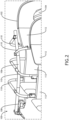
FIG. 2 is another perspective view of the passenger lift assembly shown mounted to the seat shell, in accordance with example embodiments of this disclosure; -
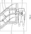
FIG. 3 is an overhead plan view of the passenger lift assembly shown mounted to the seat shell, in accordance with example embodiments of this disclosure; -
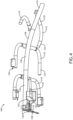
FIG. 4 is a perspective view showing the passenger lift assembly in a collapsed state, in accordance with example embodiments of this disclosure; -
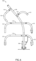
FIG. 5 is a top view showing the passenger lift assembly in a deployed state, in accordance with example embodiments of this disclosure; and -
FIG. 6 is a top view showing the passenger lift assembly in a collapsed state, in accordance with example embodiments of this disclosure. - Before explaining at least one embodiment of the inventive concepts disclosed herein in detail, it is to be understood that the inventive concepts are not limited in their application to the details of construction and the arrangement of the components or steps or methodologies set forth in the following description or illustrated in the drawings. In the following detailed description of embodiments of the instant inventive concepts, numerous specific details are set forth in order to provide a more thorough understanding of the inventive concepts. However, it will be apparent to one of ordinary skill in the art having the benefit of the instant disclosure that the inventive concepts disclosed herein may be practiced without these specific details. In other instances, well-known features may not be described in detail to avoid unnecessarily complicating the instant disclosure. The inventive concepts disclosed herein are capable of other embodiments or of being practiced or carried out in various ways. Also, it is to be understood that the phraseology and terminology employed herein is for the purpose of description and should not be regarded as limiting.
- As used herein, a letter following a reference numeral is intended to reference an embodiment of the feature or element that may be similar, but not necessarily identical, to a previously described element or feature bearing the same reference numeral (e.g., 1, 1a, 1b). Such shorthand notations are used for purposes of convenience only, and should not be construed to limit the inventive concepts disclosed herein in any way unless expressly stated to the contrary.
- Further, unless expressly stated to the contrary, "or" refers to an inclusive or and not to an exclusive or. For example, a condition A or B is satisfied by anyone of the following: A is true (or present) and B is false (or not present), A is false (or not present) and B is true (or present), and both A and B are true (or present).
- In addition, use of the "a" or "an" are employed to describe elements and components of embodiments of the instant inventive concepts. This is done merely for convenience and to give a general sense of the inventive concepts, and "a" and "an" are intended to include one or at least one and the singular also includes the plural unless it is obvious that it is meant otherwise.
- Finally, as used herein any reference to "one embodiment" or "some embodiments" means that a particular element, feature, structure, or characteristic described in connection with the embodiment is included in at least one embodiment of the inventive concepts disclosed herein. The appearances of the phrase "in some embodiments" in various places in the specification are not necessarily all referring to the same embodiment, and embodiments of the inventive concepts disclosed may include one or more of the features expressly described or inherently present herein, or any combination of sub-combination of two or more such features, along with any other features which may not necessarily be expressly described or inherently present in the instant disclosure.
- Broadly, embodiments of the inventive concepts disclosed herein are directed to a passenger lift assembly for mounting to a shell positioned in surrounding relation to a seat, and a system including a seat shell and passenger lift assembly configured for removable attachment to the seat shell. In use in an airliner, the passenger lift assembly may be retrieved from stowage, manipulated to a deployed state, mounted to a seat shell, utilized to transfer a PRM passenger from a transfer wheelchair to their seat in the airliner, removed from the seat shell, manipulated to a collapsed state, and lastly stowed in a storage space in the airliner until a next use. The passenger lift assembly collapses to a compact package to facilitate stowing in an airliner where space is limited. In some embodiments, the passenger lift assembly is reconfigurable to correspond to different motion pathways extending from, for example, and aisle to a passenger seat positioned apart from the aisle.
-
FIGS. 1 and2 illustrate thepassenger lift assembly 100 shown removably attached to aseat shell 102 positioned in surrounding relation to a passenger seat (104 inFIG. 2 ). Thepassenger lift assembly 100, also referred to herein as "theassembly 100," generally includes aspine 106 defining a motion path, alift mechanism 108 attached to thespine 106 and configured to travel along the motion path, and a plurality ofbranch subassemblies 110 attached to the spine and configured to mount to theseat shell 102 in order to position thespine 106 relative to theseat shell 102. As shown, thespine 106 is positioned suspended above and substantially centered between opposing walls of theseat shell 102. - The
spine 106 defines a motion path from a first location apart from theseat 104, to a second location proximal to theseat 104. In some embodiments, the first location may be an aisle, the second location may be over theseat 104, and the motion path from the first location to the second location may be curved. In some embodiments, the seat may be a premium class seat (e.g., business, first, super first-class seat, etc.) surrounded by theseat shell 102, wherein theseat shell 102 includes a plurality ofupstanding walls 112 defining an interior space. In embodiments, theupstanding walls 112 may be curved to define a non-linear pathway from the first location to the second location. Thespine 106 may be elongated and curved, substantially matching the curvature of the non-linear pathway, to guide motion of thelift mechanism 108 along the curved pathway to the seat. In embodiments, the lift mechanism may provide 360 degrees of rotational motion such that the passenger can be lifted from the wheelchair, rotated to a position with their back facing the pathway and seat, and guided along the pathway until reaching their seat. - In embodiments, one end of the
spine 106 may be positioned overhanging the aisle such that the lift mechanism can be positioned directly overhead a passenger seated in a wheelchair in the aisle, and the other end of thespine 106 may be positioned overhanging the passenger seat such that thelift mechanism 108 can be positioned directly above the passenger seat. In this configuration, thelift mechanism 108 can be operated to vertically raise the passenger out of the wheelchair, for instance a transfer wheelchair, and vertically lower the passenger into their respective passenger seat. The number of requiredbranch subassemblies 110 may be determined by one or more of the strength capabilities of the assembly materials, distance between spacedupstanding walls 112, curvature of the travel pathway, length of the travel pathway, etc. As shown, theassembly 100 includes twobranch subassemblies 110 that each interact with two opposingupstanding walls 112 considering the substantially transverse orientation of thebranch subassemblies 110 to theirrespective walls 112, and twobranch subassemblies 110 that interact with a singleupstanding wall 112 considering their location along a curved portion of theupstanding wall 112. The number and types ofbranch subassemblies 110 may be customized depending on the particularupstanding wall 112 configuration. -
FIG. 3 illustrates a non-limiting example of theupstanding walls 112 of theseat shell 102 defining a curved pathway from anaisle 114 to theseat 104 positioned a distance from theaisle 114. In some embodiments, the seating configuration may be a herringbone seating configuration in which the seat longitudinal axis is angled relative to the aircraft longitudinal axis. In this configuration, atransfer wheelchair 116 may be parked in theaisle 114 at the entrance to theseat 104 such that one end of thespine 106 is positioned overhead of the passenger and the opposing end of thespine 106 is positioned over theseat 104. Thespine 106 may be shaped to substantially correspond to the shape of the pathway from the aisle entrance to theseat 104. In some embodiments, thespine 106 may be positioned substantially centered along the pathway from theaisle 114 to theseat 104 to minimize the opportunity for contact of the transferring passenger with any of theupstanding walls 112 during passenger transfer. -
FIG. 4 illustrates an embodiment of theassembly 100. Thespine 106 is elongated and extends from one end of theassembly 100 to an opposing end of theassembly 100. In some embodiments, thespine 106 is tubular and made from rigid and lightweight materials such as aluminum. Thespine 106 may include a plurality ofindividual segments 118 configured to be taken apart for more compact stowage and/or to reconfigure the shape of thespine 106 to provide different shaped motion paths depending on the shape of the seat shell and length of the pathway to the seat. In some embodiments, thespine 106 may include telescoping segments for further adjustability and compact stowage. - In embodiments, each
branch subassembly 110 generally includes a fixedsegment 120 attached to thespine 106, and at least oneleg 122 rotatably coupled to the fixedsegment 120. The fixedsegments 120 may be straight and may be rotatably and/or slidably coupled to thespine 106 for further adjustability. In some embodiments, the fixedsegments 120 may be telescoping segments. Eachleg 122 may be rotatably coupled to its respective fixedsegment 120 such thatlegs 122 can be rotated between a first position in which thelegs 122 are parallel to a plane defined by thespine 106 for compact stowage, and a second position in which thelegs 122 are substantially perpendicular to the plane defined by thespine 106 to position thespine 106 at a predetermined height above the respective seat shell. As shown, all subassemblies attach along the same side of thespine 106, i.e., atop thespine 106, such that thelift mechanism 108 is able to travel along the length of thespine 106 without interference from anysubassembly 110. - In embodiments, the
lift mechanism 108 generally includes awinch 124, a hand crank 126, and ahook 128. Similar to a medical patient lift, thehook 128 is attachable to a sling (not shown) configured to be placed under or around the passenger to support the passenger during lifting. In use, the sling is positioned under or around the passenger, the sling is attached to thehook 128, and the manual crank 126 is turned to pay out or reel in a cable attached to the hook. - The
lift mechanism 108 further includes a plurality ofrollers 130 in contact with thespine 106 to facilitate smooth rolling motion of thelift mechanism 108 along the length of thespine 106. In some embodiments, therollers 130 are part of a rollingcarriage 132 supporting horizontally-oriented rollers positioned on diametrically opposed sides of thespine 106, and vertically oriented rollers positioned to engage thespine 106 on the spine side opposite the attachment side of thesubassemblies 110. Thecarriage 132 may include abracket 134 for attaching thewinch 124. In embodiments, thelift mechanism 108 travels as a single unit along the length of thespine 106 to position thehook 128 over the transfer wheelchair and the passenger seat such that the hand crank 126 can be used at each location. - In embodiments, some of the
legs 122 may sit atop their respective upstanding wall without a locking attachment, whereasother legs 122 may lockingly engage their respecting upstanding wall. Locking engagement may be provided by a latch and catch assembly wherein theleg 122 carries one of the latch and catch and the upstanding wall carries the other of the latch and catch. As shown, some of thelegs 122 may carry a latch implemented as apost 136 configured to be received in a catch implemented as an opening formed in the respective upstanding wall. In some embodiments the latch, after being inserted into the catch, may be manipulated to lock the components together. In such an embodiment, releasing the latch from the catch may require manipulating the latch in a direction opposite the locking direction. -
FIGS. 5 and6 illustrate the respective expanded and collapsed configurations of theassembly 100.FIG. 5 illustrates each of thelegs 122 rotated to their position perpendicular to the plane of thespine 106 for use of theassembly 100.FIG. 6 illustrates each of thelegs 122 rotated to a position substantially parallel to the plane of thespine 106 for stowing theassembly 100. At least one of the legs includes a latch, for instance implemented as apost 136, for locking theleg 122 to its respective upstanding wall. - The
assembly 100 includes a number ofbranch subassemblies 110, forinstance 2, 3, 4, 5... n, which are spaced apart along the length of thespine 106 to provide stable and adequate support for the weight of the transferring passenger. Considering a transfer wheelchair parked in the aisle adjacent the suite entrance, and the seat shell ending at the aisle, one end of thespine 106 may be cantilevered to be positioned in the aisle and above the wheelchair. Afirst branch subassembly 110 may be positioned inward from the cantilevered end of thespine 106 andsuccessive branch subassemblies 110 spaced apart to the opposing end of the spine. Somebranch subassemblies 110, and in particular the fixed segments, may be oriented perpendicular to thespine 106 at their point of attachment whereas other fixed segments may be oriented at a different angle depending on the curvature of the spine and upstanding walls. - Some
branch subassemblies 110 may include a single leg configuration whereas other branch assemblies may include a double leg configuration, depending on the need for more than one leg and interference with anotherbranch subassembly 110. Although not shown, thespine 106 may include a mechanical stop at each end for defining the total length of the motion path and preventing thelift mechanism 108 from leaving thespine 106. As stated above, each of thespine 106 and thebranch subassemblies 110 may be constructed from segments so that theassembly 100 can be taken apart for stowing or reconfigurability to accommodate a different length and/or shaped motion path or seat shell configuration. - In a non-limiting application, a passenger cabin may be configured with a number of repeating suites defined by spaced upstanding walls, for instance in a herringbone configuration or reverse herringbone configuration in which the seat within each suite is angled relative to the aircraft longitudinal axis. To enhance privacy, the upstanding walls may be linear proximal to the seat and curve as they approach the aisle, thus providing a non-linear pathway from the aircraft longitudinal aisle the passenger seat. The passenger cabin may be equipped with a
lift assembly 100 according to the present disclosure that corresponds in pathway shape and length to the pathway from each seat to the aisle. Certain ones or all of the suites in the cabin, for instance certain suites along one side of the longitudinal aircraft aisle, may be compatible for use with thelift assembly 100. When needed, thelift assembly 100 may be retrieved from a stowage compartment, manipulated to its use configuration, installed atop the respective upstanding walls, and used to transfer a PRM from the aisle to their seat. After transfer is complete, thelift assembly 100 is removed from the upstanding walls, manipulated to is stowed configuration, and returned to its designated stowage space. - From the above description, it is clear that the inventive concepts disclosed herein are well adapted to achieve the objectives and to attain the advantages mentioned herein as well as those inherent in the inventive concepts disclosed herein. While presently preferred embodiments of the inventive concepts disclosed herein have been described for purposes of this disclosure, it will be understood that numerous changes may be made which will readily suggest themselves to those skilled in the art and which are accomplished within the broad scope and coverage of the inventive concepts disclosed and claimed herein.
Claims (15)
- A passenger lift assembly (100), comprising:a spine (106) defining a motion path;a lift mechanism (108) attached to the spine and configured to travel along the motion path; anda plurality of branch subassemblies (110) attached to the spine, each branch subassembly comprising at least one leg (122) configured to engage an upstanding wall of a seat shell positioned in relation to a passenger seat.
- The passenger lift assembly (100) according to claim 1, wherein the at least one leg (122) is configured to removably attach to the upstanding wall via a latch and catch assembly, and the at least one leg comprises one of a catch and a latch (136).
- The passenger lift assembly (100) according to claim 1 or 2, wherein:each branch subassembly (110) further comprises a fixed segment (120) attached to the spine (106); andthe at least one leg (122) is rotatably coupled to the fixed segment.
- The passenger lift assembly (100) according to any preceding claim, wherein the spine (106) is elongated and curved.
- The passenger lift assembly (100) according to any preceding claim, wherein each leg (122) is configured to rotate between a first position parallel to a plane of the spine (106) and a second position perpendicular to the plane of the spine (106).
- The passenger lift assembly (100) according to any preceding claim, wherein the lift mechanism (108) comprises a winch (124), a hook (128), a manual crank (126), and a plurality of rollers (130) configured to roll along the spine (106).
- The passenger lift assembly (100) according to any preceding claim, wherein each of the spine (106), the fixed segments (120), and the legs (122) are cylindrical tubes, and wherein the plurality of branch subassemblies (110) are telescoping assemblies.
- The passenger lift assembly (100) according to any preceding claim, wherein the spine (106), the fixed segments (120), and the legs (122) are aluminum.
- The passenger lift assembly (100) according to any preceding claim, wherein the spine (106) comprises a plurality of removably attachable spine segments (118).
- A seat assembly, comprising:a seat shell (102) including upstanding walls (112) positioned in relation to a seat (104); anda passenger lift assembly (100) removably attachable to the seat shell (102), the passenger lift assembly (100) comprising:a spine (106) defining a motion path;a lift mechanism (108) attached to the spine and configured to travel along the motion path; anda plurality of branch subassemblies (110) attached to the spine, each branch subassembly comprising at least one leg (122) removably attachable to one of the upstanding walls (112) to position the spine overhead of the seat (104).
- The seat assembly according to claim 10, wherein each leg (122) attaches to its respective upstanding wall (112) via a latch and catch assembly (136).
- The seat assembly according to claim 10 or 11, wherein:each branch subassembly (110) further comprises a fixed segment (120) attached to the spine (106), the at least one leg (122) rotatably coupled to the fixed segment;the spine (106) is elongated; andeach leg (122) is configured to rotate between a first position parallel to a plane of the spine and a second position perpendicular to the plane of the spine.
- The seat assembly according to any of claims 10-12, wherein the upstanding walls (112) define a path therebetween that leads to the seat (104), and the spine (106) is positioned overhead of the path to the seat (104) for transferring a passenger from an aisle to the seat (104) using the passenger lift assembly (100) temporarily mounted to the seat shell (102).
- The seat assembly according to any of claims 10-13, wherein:the upstanding walls (112) define an interior space therebetween; andthe plurality of branch subassemblies (110)are configured to span the interior space to position the spine (106) substantially centered over the interior space.
- The seat assembly according to claim 14, wherein the upstanding walls (112) are curved, the spine (106) is curved, and a curvature of the spaced upstanding walls substantially matches a curvature of the spine.
Applications Claiming Priority (1)
| Application Number | Priority Date | Filing Date | Title |
|---|---|---|---|
| US18/215,387 US12544286B2 (en) | 2023-06-28 | 2023-06-28 | Collapsible shell mounted passenger lift assembly |
Publications (1)
| Publication Number | Publication Date |
|---|---|
| EP4484288A1 true EP4484288A1 (en) | 2025-01-01 |
Family
ID=91621316
Family Applications (1)
| Application Number | Title | Priority Date | Filing Date |
|---|---|---|---|
| EP24183558.6A Pending EP4484288A1 (en) | 2023-06-28 | 2024-06-20 | Collapsible shell mounted passenger lift assembly |
Country Status (2)
| Country | Link |
|---|---|
| US (1) | US12544286B2 (en) |
| EP (1) | EP4484288A1 (en) |
Citations (6)
| Publication number | Priority date | Publication date | Assignee | Title |
|---|---|---|---|---|
| EP0027638A1 (en) * | 1979-10-18 | 1981-04-29 | Idé-Produktion Carin AB | A device for vertical and horizontal transport of loads into and out of a vehicle or the like |
| CA2390260A1 (en) * | 1998-11-06 | 2000-05-18 | Robert G. Cheeseboro | Personal transporter |
| CN201394144Y (en) * | 2009-05-15 | 2010-02-03 | 崔新明 | Hoisting type patient-nursing installation |
| EP3205321A1 (en) * | 2016-02-10 | 2017-08-16 | Peter Bosgraaf | A personal transporter for transferring a person with restricted mobility to and from a seat in an aircraft and an assembly of a personal transporter and a wheelchair |
| EP3919389A1 (en) * | 2020-06-05 | 2021-12-08 | B/E Aerospace, Inc. | Private suite for economy cabin space in aircraft |
| CN113893108B (en) * | 2021-09-30 | 2022-09-27 | 安徽医科大学第一附属医院 | A lifting device for paralyzed patients |
Family Cites Families (10)
| Publication number | Priority date | Publication date | Assignee | Title |
|---|---|---|---|---|
| US4003479A (en) | 1975-06-04 | 1977-01-18 | Reyer William J | Hoist and transporting apparatus |
| CA2433816C (en) * | 2003-06-25 | 2010-07-13 | Prodije 9061-7457 Quebec Inc. | Dismountable multi-position stander |
| WO2006032108A2 (en) | 2004-09-24 | 2006-03-30 | Haycomp Pty Ltd | Apparatus for transferring a person from a wheelchair to a fixed seat |
| WO2008007222A2 (en) | 2006-07-07 | 2008-01-17 | Arjo Hospital Equipment Ab | Hoist device with sling attachment division |
| WO2011163283A2 (en) | 2010-06-22 | 2011-12-29 | Wilson Harold R | Wheelchair lift transfer device |
| US8690127B2 (en) | 2011-05-09 | 2014-04-08 | James C. Patterman, III | Vehicle lift system accessory |
| CA2912396A1 (en) | 2013-05-17 | 2014-11-20 | Dane Technologies, Inc. | Devices relating to multifunctional aircraft aisle wheelchair |
| US20150056050A1 (en) * | 2013-08-20 | 2015-02-26 | Julian Alex Decuir, JR. | Wheelchair |
| CN211797334U (en) * | 2018-08-31 | 2020-10-30 | 希尔-罗姆服务公司 | Patient rotation system |
| US11786430B2 (en) * | 2019-02-11 | 2023-10-17 | Liko Research & Development Ab | Patient lift and sling having wireless communication |
-
2023
- 2023-06-28 US US18/215,387 patent/US12544286B2/en active Active
-
2024
- 2024-06-20 EP EP24183558.6A patent/EP4484288A1/en active Pending
Patent Citations (6)
| Publication number | Priority date | Publication date | Assignee | Title |
|---|---|---|---|---|
| EP0027638A1 (en) * | 1979-10-18 | 1981-04-29 | Idé-Produktion Carin AB | A device for vertical and horizontal transport of loads into and out of a vehicle or the like |
| CA2390260A1 (en) * | 1998-11-06 | 2000-05-18 | Robert G. Cheeseboro | Personal transporter |
| CN201394144Y (en) * | 2009-05-15 | 2010-02-03 | 崔新明 | Hoisting type patient-nursing installation |
| EP3205321A1 (en) * | 2016-02-10 | 2017-08-16 | Peter Bosgraaf | A personal transporter for transferring a person with restricted mobility to and from a seat in an aircraft and an assembly of a personal transporter and a wheelchair |
| EP3919389A1 (en) * | 2020-06-05 | 2021-12-08 | B/E Aerospace, Inc. | Private suite for economy cabin space in aircraft |
| CN113893108B (en) * | 2021-09-30 | 2022-09-27 | 安徽医科大学第一附属医院 | A lifting device for paralyzed patients |
Also Published As
| Publication number | Publication date |
|---|---|
| US12544286B2 (en) | 2026-02-10 |
| US20250000730A1 (en) | 2025-01-02 |
Similar Documents
| Publication | Publication Date | Title |
|---|---|---|
| US5490703A (en) | Patient transport system | |
| US12370099B2 (en) | Litter lift system | |
| RU2560250C2 (en) | System of supporting stretchers for medical care blocks and set of bearing lever, applied in it | |
| EP2803580B1 (en) | Holding device for passenger seats and passenger seating system with flexible seating arrangement for means of passenger transport | |
| US5779296A (en) | Patient transport system | |
| CN113353266B (en) | Stowable cabin attendant seat with vertical sliding backrest | |
| US10532827B2 (en) | Modular staircase | |
| US20050218265A1 (en) | An integrated transport system and method for overhead stowage and retrieval | |
| US5769360A (en) | Easy transport seat | |
| US8540474B2 (en) | Power lift and transfer system and method | |
| US8602475B2 (en) | Seat mounted extendable litter system | |
| US11051998B2 (en) | Portable and collapsible support structures and related methods | |
| US12544286B2 (en) | Collapsible shell mounted passenger lift assembly | |
| EP4227219A1 (en) | Use of forward closet in single aisle aircraft for wheelchair accommodation | |
| US8413588B2 (en) | Railway service vehicle having wheelchair restraint | |
| US20120280541A1 (en) | Retractable passenger seat | |
| JP3378867B2 (en) | Light aircraft cargo hold | |
| US20060243850A1 (en) | Fastening device for fastening a movable element | |
| US12534203B2 (en) | Person with reduced mobility stretcher and wheelchair monument for aircraft systems | |
| US8657353B2 (en) | Auto deployed cargo loading rail system and medic seat in-truck travel rail | |
| JP2009511334A (en) | Vertical movable passage for a break room in the ceiling area | |
| DE4218239C2 (en) | Airship for the transportation of goods and people | |
| EP4140887A1 (en) | Foldable attendant step | |
| WO2008138138A1 (en) | Wheelchair | |
| US12575982B2 (en) | Transport of passengers with reduced mobility |
Legal Events
| Date | Code | Title | Description |
|---|---|---|---|
| PUAI | Public reference made under article 153(3) epc to a published international application that has entered the european phase |
Free format text: ORIGINAL CODE: 0009012 |
|
| STAA | Information on the status of an ep patent application or granted ep patent |
Free format text: STATUS: THE APPLICATION HAS BEEN PUBLISHED |
|
| AK | Designated contracting states |
Kind code of ref document: A1 Designated state(s): AL AT BE BG CH CY CZ DE DK EE ES FI FR GB GR HR HU IE IS IT LI LT LU LV MC ME MK MT NL NO PL PT RO RS SE SI SK SM TR |
|
| STAA | Information on the status of an ep patent application or granted ep patent |
Free format text: STATUS: REQUEST FOR EXAMINATION WAS MADE |
|
| 17P | Request for examination filed |
Effective date: 20250613 |