EP4484273A1 - Controlling a marine vehicle propulsion system - Google Patents
Controlling a marine vehicle propulsion system Download PDFInfo
- Publication number
- EP4484273A1 EP4484273A1 EP23182754.4A EP23182754A EP4484273A1 EP 4484273 A1 EP4484273 A1 EP 4484273A1 EP 23182754 A EP23182754 A EP 23182754A EP 4484273 A1 EP4484273 A1 EP 4484273A1
- Authority
- EP
- European Patent Office
- Prior art keywords
- values
- request
- propeller
- cyclorotor
- value
- Prior art date
- Legal status (The legal status is an assumption and is not a legal conclusion. Google has not performed a legal analysis and makes no representation as to the accuracy of the status listed.)
- Pending
Links
Images


Classifications
-
- B—PERFORMING OPERATIONS; TRANSPORTING
- B63—SHIPS OR OTHER WATERBORNE VESSELS; RELATED EQUIPMENT
- B63H—MARINE PROPULSION OR STEERING
- B63H25/00—Steering; Slowing-down otherwise than by use of propulsive elements; Dynamic anchoring, i.e. positioning vessels by means of main or auxiliary propulsive elements
- B63H25/42—Steering or dynamic anchoring by propulsive elements; Steering or dynamic anchoring by propellers used therefor only; Steering or dynamic anchoring by rudders carrying propellers
-
- B—PERFORMING OPERATIONS; TRANSPORTING
- B63—SHIPS OR OTHER WATERBORNE VESSELS; RELATED EQUIPMENT
- B63H—MARINE PROPULSION OR STEERING
- B63H1/00—Propulsive elements directly acting on water
- B63H1/02—Propulsive elements directly acting on water of rotary type
- B63H1/04—Propulsive elements directly acting on water of rotary type with rotation axis substantially at right angles to propulsive direction
- B63H1/06—Propulsive elements directly acting on water of rotary type with rotation axis substantially at right angles to propulsive direction with adjustable vanes or blades
- B63H1/08—Propulsive elements directly acting on water of rotary type with rotation axis substantially at right angles to propulsive direction with adjustable vanes or blades with cyclic adjustment
- B63H1/10—Propulsive elements directly acting on water of rotary type with rotation axis substantially at right angles to propulsive direction with adjustable vanes or blades with cyclic adjustment of Voith Schneider type, i.e. with blades extending axially from a disc-shaped rotary body
-
- B—PERFORMING OPERATIONS; TRANSPORTING
- B63—SHIPS OR OTHER WATERBORNE VESSELS; RELATED EQUIPMENT
- B63H—MARINE PROPULSION OR STEERING
- B63H21/00—Use of propulsion power plant or units on vessels
- B63H21/21—Control means for engine or transmission, specially adapted for use on marine vessels
-
- B—PERFORMING OPERATIONS; TRANSPORTING
- B63—SHIPS OR OTHER WATERBORNE VESSELS; RELATED EQUIPMENT
- B63H—MARINE PROPULSION OR STEERING
- B63H1/00—Propulsive elements directly acting on water
- B63H1/02—Propulsive elements directly acting on water of rotary type
-
- B—PERFORMING OPERATIONS; TRANSPORTING
- B63—SHIPS OR OTHER WATERBORNE VESSELS; RELATED EQUIPMENT
- B63H—MARINE PROPULSION OR STEERING
- B63H1/00—Propulsive elements directly acting on water
- B63H1/02—Propulsive elements directly acting on water of rotary type
- B63H1/12—Propulsive elements directly acting on water of rotary type with rotation axis substantially in propulsive direction
- B63H1/14—Propellers
- B63H1/28—Other means for improving propeller efficiency
-
- B—PERFORMING OPERATIONS; TRANSPORTING
- B63—SHIPS OR OTHER WATERBORNE VESSELS; RELATED EQUIPMENT
- B63H—MARINE PROPULSION OR STEERING
- B63H1/00—Propulsive elements directly acting on water
- B63H1/02—Propulsive elements directly acting on water of rotary type
- B63H1/04—Propulsive elements directly acting on water of rotary type with rotation axis substantially at right angles to propulsive direction
- B63H1/06—Propulsive elements directly acting on water of rotary type with rotation axis substantially at right angles to propulsive direction with adjustable vanes or blades
- B63H1/08—Propulsive elements directly acting on water of rotary type with rotation axis substantially at right angles to propulsive direction with adjustable vanes or blades with cyclic adjustment
- B63H1/10—Propulsive elements directly acting on water of rotary type with rotation axis substantially at right angles to propulsive direction with adjustable vanes or blades with cyclic adjustment of Voith Schneider type, i.e. with blades extending axially from a disc-shaped rotary body
- B63H2001/105—Propulsive elements directly acting on water of rotary type with rotation axis substantially at right angles to propulsive direction with adjustable vanes or blades with cyclic adjustment of Voith Schneider type, i.e. with blades extending axially from a disc-shaped rotary body with non-mechanical control of individual blades, e.g. electric or hydraulic control
-
- B—PERFORMING OPERATIONS; TRANSPORTING
- B63—SHIPS OR OTHER WATERBORNE VESSELS; RELATED EQUIPMENT
- B63H—MARINE PROPULSION OR STEERING
- B63H5/00—Arrangements on vessels of propulsion elements directly acting on water
- B63H5/02—Arrangements on vessels of propulsion elements directly acting on water of paddle wheels, e.g. of stern wheels
- B63H2005/025—Arrangements on vessels of propulsion elements directly acting on water of paddle wheels, e.g. of stern wheels of Voith Schneider type
-
- B—PERFORMING OPERATIONS; TRANSPORTING
- B63—SHIPS OR OTHER WATERBORNE VESSELS; RELATED EQUIPMENT
- B63H—MARINE PROPULSION OR STEERING
- B63H21/00—Use of propulsion power plant or units on vessels
- B63H21/21—Control means for engine or transmission, specially adapted for use on marine vessels
- B63H2021/216—Control means for engine or transmission, specially adapted for use on marine vessels using electric control means
Definitions
- the invention relates to a method of controlling a marine vehicle propulsion system.
- a marine vehicle may move with respect to water around it with thrust from a propulsion system, which includes one or more cyclorotor propellers with blades that extend from the propeller, e.g., perpendicularly or with a tilted angle.
- a propulsion system which includes one or more cyclorotor propellers with blades that extend from the propeller, e.g., perpendicularly or with a tilted angle.
- Such propulsion system would benefit from a controlling system capable of producing a desired force and/or torque requested by a user via simple steering equipment such as a joystick.
- Embodiments and examples of the method described herein may be implemented in any cyclorotor propulsion system with individually controllable blades.
- Figures illustrate various embodiments, they are simplified diagrams that only show some structures and/or functional entities.
- the connections shown in Figures may refer to logical or physical connections. It is apparent to a person skilled in the art that the described apparatus and/or system may also comprise other functions and structures than those described in Figures and text. It should be appreciated that details of some functions, structures, and the signalling used for measurement and/or controlling are irrelevant to the actual invention. Therefore, they need not be discussed in more detail here.
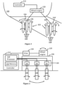
- FIG 1 illustrates an example of a marine vehicle 100 (the marine vehicle is partly shown in Figure 1 ) with a propulsion system 102, which comprises one or more propulsion sub-systems 104, 104'.
- Marine vehicles may include transport vessels and passenger ships, and the term marine vehicle or marine vessel may generally refer to any craft designed for water transportation, for example.
- the transport ships may include cargo vessels and containers, for example.
- the marine vehicles may refer to fishing vessels, service craft like tugboats and supply vessels, and warships.
- the marine vehicles may be used as ferries and submarines. It is apparent to a person skilled in the art that the marine vehicle comprises any number of shown elements, other equipment, other functions, and other structures that are not illustrated. They, as well as the protocols used, are well known by persons skilled in the art and are irrelevant to the actual invention. Therefore, they need not to be discussed in more detail here.
- the propulsion sub-system 104, 104' is a cyclorotor propeller that may be capable of producing both a cycloidal trajectory and a trochoidal trajectory depending on the propeller's advance ratio.
- the advance ratio may be understood as the ratio of freestream fluid speed to the propeller's tip speed.
- Each exemplary propulsion sub-system 104, 104' comprises a propeller wheel 106, 106' and at least two blades 108, 108' that may extend from the wheel 106, 106' perpendicularly with respect to the rotational plane of the wheel 106, 106'.
- the blades 108, 108' are attached with the propeller wheel 106, 106' in a rotatable manner.
- the blades 108, 108' of the propulsion sub-system 104, 104' may be individually controllable in a rotatable manner with respect to the propeller wheel 106, 106' such that a desirable blade position and/or speed can be obtained fully independently for the blades 108, 108'.
- the blades 108, 108' may be jointly controllable and coupled to the propeller wheel 106, 106', e.g., mechanically through suitable joints and/or gears, such that the desirable blade position and/or speed may be obtained for the blades 108, 108'.
- the blades 108, 108' may be coupled to achieve a constant phase difference between the rotation of individual blades.
- a wheel engine system 120 may be common to a plurality of the propulsion sub-systems 104, 104' through a mechanical power transmission.
- each or some of the propulsion sub-systems 104, 104' may have a separate wheel engine system 120.
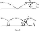
- Figure 2 illustrates an example where the propulsion system 102 comprises one cyclorotor propeller wheel 106 with individually controllable blades 108. That is, the propulsion system 102 may correspond to one of the propulsion sub-systems 104, 104'. Additionally, the exemplary propulsion system 102 comprises an actuator arrangement 110 and a controller 112. The actuator arrangement 110 is operably coupled to the blades 108 and is configured to rotate the blades.
- the controller 112 may be common to the propulsion sub-systems 104, 104' (see Figure 1 ) or the controller 112 may comprise a plurality of sub-controllers, a sub-controller per propulsion sub-system 104, 104' (such a possibility is illustrated in Figure 2 although the controller 112 in Figure 2 may also exist for the plurality of cyclorotor propellers).
- the controller 112 comprises one or more processors 114 and one or more memories 116 including computer program code.
- the one or more memories 116 and the computer program code cause the controller 112, with the one or more processors 114, to determine values for a set of control parameters.
- the controller 112 then communicates the values for the set of control parameters to the actuator arrangement 110, which sets the at least two blades 108, for example, at blade position and blade speed based on the values of the set of control parameters determined by the controller 112.
- the actuator arrangement 110 may comprise an electric motor arrangement AR per a blade of the at least two blades 108, wherein the electric motor arrangement AR is operably coupled to the respective blade 108.
- the electric motor arrangement AR may be configured to rotate the respective blade 108 around the blade's longitudinal axis as illustrated in the example of Figure 2 .
- the electric motor arrangement AR may comprise a regulator, a gearbox, and an electric motor (blade motor), which turns the blade it is mechanically coupled with according to the values of the control parameters received from the controller 112, for example.
- Functionalities of the propeller wheel 106 and the at least two blades 108 explained with Figure 2 may correspondingly be also applied to the propeller wheel 106' and blades 108' in Figure 1 .
- the controller 112 may also control a drive 118 of the wheel engine system 120.
- the wheel engine system 120 may comprise an engine (motor), which may comprise an electric engine, a combustion engine such as, for example, a diesel engine, petrol engine, or a gas engine, and potentially a mechanical gearbox.
- the configuration of the drive 118 may depend on the type of the engine. If the wheel engine system 120 comprises one or more electric engines (electric motors), the drive 118 may comprise an electric drive configured to control the electric engine(s), for example.
- the controller 112 may send a command to the drive 118 which may then control a rotation speed and/or a direction of rotation of the engine of the wheel engine system 120.
- the wheel engine system 120 can rotate the propeller wheel 106 directly or through the gearbox, for example.
- each of the propulsion sub-systems 104, 104' may have its own wheel engine system 120.
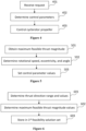
- Figure 3 illustrates examples of trochoidal and epicycloidal trajectories of the cyclorotor propeller.
- the upper illustrated trajectory of the cyclorotor propeller is a trochoidal trajectory.
- the trochoidal trajectory may be used, e.g., during transit movement of the marine vessel.
- the trochoidal trajectory corresponds to advance coefficient (advance ratio, advance parameter) values that are greater than one ( ⁇ , > 1).
- the advance coefficient may be understood as a ratio of a forward speed (vessel advance speed) V a to a rotational tip speed V r .
- the lower illustrated trajectory of the cyclorotor propeller is an epicycloidal trajectory.
- the epicycloidal trajectory may be used, e.g., during bollard pull operation of the marine vessel.
- the epicycloidal trajectory corresponds to advance coefficient values that are smaller than one ( ⁇ , ⁇ 1).
- Figure 4 illustrates an example of the controlling method for a marine vehicle propulsion system comprising a cyclorotor propeller, an actuator arrangement, and a controller.
- a request is received in block 401 by the controller.
- the request comprises at least one force request and/or at least one torque request.
- the at least one force request may comprise, e.g., a thrust request.
- the request may comprise a mode request.
- the mode request may be understood to comprise, e.g., information of a mode of the marine vehicle, such as a transit mode, a bollard pull mode, or a rudder mode.
- the request may be received, for example, from a bridge of the marine vehicle.
- the bridge may comprise steering equipment such as a manual joystick or a rudder by which a user may convoy the request.
- Values for a set of control parameters are determined in block 402 by the controller based on the request.
- the set of control parameters comprises at least one thrust magnitude parameter and at least one thrust direction parameter.
- the at least one thrust magnitude parameter may be, e.g., a rotational speed of the cyclorotor propeller and/or an eccentricity of the cyclorotor propeller.
- the at least one thrust direction parameter may be, e.g., a yaw angle of the cyclorotor propeller and/or an offset angle of an angle of attack of the cyclorotor propeller.
- the values for the control parameters are determined by using an optimization method constrained by the request received and a pre-determined set of constraints for the control parameters using standard algorithms for constrained optimization.
- the optimization method comprises maximizing hydrodynamic efficiency of the cyclorotor propeller.
- the order and coefficients of the efficiency equation may be determined based on an acceptable accuracy during mathematical modelling process using, e.g., computational fluid dynamics (CFD) simulation, lab experiments, and/or sea trial.
- CFD computational fluid dynamics
- the optimization problem formulated above is nonconvex and nonlinear due to the mathematical functions f , g x , and g y used for modelling energy efficiency and thrust.
- Optimization methods that may be employed to solve the optimization problem comprise, e.g., Sequential Quadratic Programming (SQP), interior-point (IP) methods, and Genetic Algorithm.
- the Sequential Quadratic Programming may be understood as an iterative method that solves nonlinear programming problems by iteratively solving a sequence of quadratic subproblems.
- the interior-point methods may be understood to solve optimization problems by finding a solution in an interior of a feasible region.
- the Genetic Algorithm is a population-based stochastic search algorithm inspired by natural selection process. However, the details of the optimization methods are irrelevant to the actual invention and a person skilled in the art is familiar with various optimization methods, per se. Therefore, they need not be discussed in more detail here.
- the pre-determined set of constraints for the control parameters may comprise upper and lower constraints for the control parameters, which may be expressed with equations: ⁇ L ⁇ ⁇ ⁇ ⁇ U , rpm L ⁇ rpm ⁇ rpm U , ⁇ L ⁇ ⁇ ⁇ ⁇ U , where superscripts L and U denote lower and upper constraints, respectively.
- the pre-determined set of constraints may also comprise other constraints for preventing determining unfeasible values for the set of control parameters such as, for example, 1 for eccentricity. If the request comprises the mode request, the pre-determined set of constraints for the control parameters may also depend on the mode request.
- the maximizing the hydrodynamic efficiency of the cyclorotor propeller may comprise determining values for operating condition parameters such as a current vessel velocity.
- the maximizing the hydrodynamic efficiency of the cyclorotor propeller may also comprise obtaining from a pre-determined feasibility solution set feasible thrust values corresponding to the request received and to the operating condition parameters determined.
- the feasible thrust values may comprise a maximum value for the thrust magnitude parameter and/or feasible values for the thrust direction parameter.
- the cyclorotor propeller is controlled in block 403 based on the control parameter values by the actuator arrangement receiving the values for the set of control parameters from the controller.
- the values for the control parameters may be determined and the cyclorotor propeller controlled based on the values, e.g., at least once per a revolution of the cyclorotor propeller.
- the values for the control parameters may be determined and the cyclorotor propeller controlled based on the values when a blade position changes, e.g., a pre-determined amount.
- the pre-determined set of constraints may also comprise constraints or feasible values for other factors, aspects, or features of the cyclorotor propeller such as, e.g., vibration of the cyclorotor propeller, noise produced by the cyclorotor propeller, or cavitation of the cyclorotor propeller.
- Figure 5 illustrates an example of the controlling method, wherein the request comprises at least a thrust magnitude request and a thrust direction request, and the pre-determined feasibility solution set is a first feasibility solution set.
- the thrust vector may be represented via a thrust magnitude Thrust M and a thrust angle Thrust angle , or via a forward component Thrust x and a lateral component Thrust y as explained above.
- Thrust x Thrust M ⁇ cos Thrust angle
- Thrust y Thrust M ⁇ sin Thrust angle
- Thrust M 2 Thrust x 2 + Thrust y 2 , where cos denotes the cosine function and sin denotes the sine function.
- a maximum feasible thrust magnitude corresponding to the values for the operating condition parameters and the thrust direction request is obtained in block 501 from the first feasibility solution set.
- the maximum feasible thrust value may be used as a further constraint in the maximizing the hydrodynamic efficiency of the cyclorotor propeller, expressed for example as an equation: Thrust M ⁇ min Thrust max , Thrust req , where Thrust max denotes the maximum feasible thrust magnitude obtained, and Thrust req denotes the thrust magnitude request.
- a first rotational speed value, a first eccentricity value, and a first yaw angle value are determined in block 502 based on at least the thrust direction request, the thrust magnitude request, the maximum feasible thrust magnitude obtained, and the pre-determined set of constraints, such that the first rotational speed value, the first eccentricity value, and the first yaw angle value maximize the hydrodynamic efficiency of the cyclorotor propeller.
- the first rotational speed value, the first eccentricity value, and the first yaw angle value may be determined, for example, by maximizing the objective function f using standard algorithms for constrained optimization as explained in more detail above.
- the first rotational speed value, the first eccentricity value, and the first yaw angle value are set in block 503 as values for the set of control parameters.
- Figure 6 illustrates an example of determining the first feasibility solution set used in the controlling method illustrated above with Figure 5 .
- a thrust direction range and a plurality of thrust direction values are determined in block 601.
- the thrust direction range may be 0°-360° (0-2 ⁇ rad) or a smaller range.
- the thrust direction values may be, e.g., angle values at equal intervals within the range.
- a maximum feasible thrust magnitude value is determined in block 602, per a thrust direction value of the plurality of thrust direction values determined, based on at least the thrust direction value, the values for the operating condition parameters, and the pre-determined set of constraints.
- the maximum feasible thrust magnitude may be determined, for example, by using standard algorithms for constrained optimization as explained in more detail above.
- the plurality of thrust direction values and the values for the operating condition parameters are stored in block 603 in the first feasibility solution set.
- the maximum feasible thrust magnitude value corresponding to the thrust direction value and the values for the operating condition parameters is also stored in block 603, per a thrust direction value of the plurality of thrust direction values, in the first feasibility solution set.
- Figure 7 illustrates an example of the controlling method, wherein the request comprises at least a sway force request, a surge force request, and a yaw torque request, and the pre-determined feasibility solution set is a second feasibility solution set.
- a set of feasibility constraints corresponding to the current available power and the values for the operating condition parameters is obtained in block 702 from the second feasibility solution set.
- the set of feasibility constraints comprises a maximum feasible sway force, a minimum feasible sway force, a maximum feasible surge force, a minimum feasible surge force, a maximum feasible yaw torque, and a minimum feasible yaw torque.
- a second rotational speed value, a second eccentricity value, and a second yaw angle value are determined in block 703 based on at least the sway force request, the surge force request, the yaw torque request, the set of feasibility constraints obtained, and the pre-determined set of constraints, such that the second rotational speed value, the second eccentricity value, and the second yaw angle value maximize the hydrodynamic efficiency of the cyclorotor propeller.
- the second rotational speed value, the second eccentricity value, and the second yaw angle value may be determined, for example, by maximizing the objective function f using standard algorithms for constrained optimization as explained in more detail above.
- the pre-determined set of constraints may comprise at least an upper constraint and a lower constraint for rotational speed, an upper constraint and a lower constraint for eccentricity, and an upper constraint and a lower constraint for yaw angle.
- the second rotational speed value, the second eccentricity value, and the second yaw angle value are set in block 704 as the values for the set of control parameters.
- Figure 8 illustrates an example of determining the second feasibility solution set used in the controlling method illustrated above with Figure 7 .
- electrical power consumption of the cyclorotor propeller and generated thrust of the cyclorotor are determined in block 801.
- the set of feasibility constraints comprising the maximum feasible sway force, the minimum feasible sway force, the maximum feasible surge force, the minimum feasible surge force, the maximum feasible yaw torque, and the minimum feasible yaw torque is determined in block 802 based on the electrical power consumption of the cyclorotor propeller determined, the generated thrust of the cyclorotor propeller determined, the current available power, the values for the operating condition parameters, and the pre-determined set of constraints.
- the current available power and the values for the operating condition parameters are stored in block 803 in the second feasibility solution set.
- the set of feasibility constraints corresponding to the current available power and the operating condition parameters is also stored in block 803 in the second feasibility solution set.
- the optimization method comprises minimizing a factor of the cyclorotor propeller constrained by the request received and another pre-determined set of constraints for the control parameters.
- the factor of the cyclorotor propeller may be understood as an unwanted factor or aspect such as, e.g., vibration of the cyclorotor propeller, noise produced by the cyclorotor propeller, cavitation of the cyclorotor propeller, or another factor of the cyclorotor propeller of which minimization would be beneficial.
- Maximizing the hydrodynamic efficiency of the cyclorotor propeller may enable calculating optimal values for the control parameters which can be requested by the controller of the marine vehicle with a joystick or by an automatic controller while achieving maximal efficiency regarding to power consumption.
- Minimizing an unwanted factor of the cyclorotor propeller may enable calculating optimal values for the control parameters which can be requested by the controller of the marine vehicle with a joystick or by an automatic controller while, e.g., reducing wearing functioning of the cyclorotor propeller.
- Using the pre-determined feasibility solution set may improve performance of controlling a marine vehicle propulsion system.
- the pre-determined feasibility solution set may prevent oscillations and instability during operation and hence increase lifetime of the propulsion system. Additionally, it may function as an advisory option for a marine vehicle operator to enable the operator to be continuously aware of capability of the propulsion system in current operating conditions.
- Figure 9 is a simplified block diagram illustrating some units for an apparatus (device, equipment) 900 configured to perform at least some functionality described above for controlling the propulsion of a marine vehicle, for example by means of Figures 1 to 8 and any combination thereof.
- the apparatus 900 comprises one or more interface (IF) entities 901, such as one or more user interfaces, and one or more processing entities 902 connected to various interface entities 901 and to one or more memories 903.
- IF interface
- processing entities 902 connected to various interface entities 901 and to one or more memories 903.
- the one or more interface entities 901 are entities for receiving and transmitting information, such as communication interfaces comprising hardware and/or software for realising communication connectivity according to one or more communication protocols, or for realising data storing and fetching, or for providing user interaction via one or more user interfaces as described above in the explanation of the example illustrated by Figures 1 and 2 .
- a processing entity 902 is capable to perform calculations and configured to implement at least part of functionalities/operations described above, for example by means of any of Figures 1 to 8 and any combination thereof, with corresponding algorithms 904 stored in the memory 903.
- the entity 902 may include one or more processors, controllers, control units, micro-controllers, etc. configurable to carry out embodiments/examples/implementations or operations described above, for example by means of any of Figures 1 to 8 and any combination thereof.
- a processor is a central processing unit, but the processor entity 902 may be an additional operation processor or a multicore processor or a microprocessor.
- a memory 903 is usable for storing a computer program code required for one or more functionalities/operations described above, for example by means of any of Figures 1 to 8 and any combination thereof, that is, the algorithms 904 for implementing the functionality/operations described above by means of any of Figures 1 to 8 and any combination thereof.
- the memory 903 may also be usable for storing, at least temporarily, other possible information required for one or more functionalities/operations described above, for example by means of any of Figures 1 to 8 and any combination thereof.
- the memory 903 may comprise a data buffer that may, at least temporarily, store for example measurement data and/or information received as a user input.
- the methods described herein may be configured as a computer or a processor, or a microprocessor, such as a single-chip computer element, or as a chipset, or one or more logic gates including at least a memory for providing storage area used for arithmetic operation and an operation processor for executing the arithmetic operation.
- Each or some or one of the algorithms for functions/operations described above, for example by means of any of Figures 1 to 8 and any combination thereof, may be comprised in one or more computer processors, application-specific integrated circuits (ASIC), digital signal processors (DSP), digital signal processing devices (DSPD), programmable logic devices (PLD), field-programmable gate arrays (FPGA), graphics processing units (GPU) and/or other hardware components that have been programmed and/or will be programmed by downloading computer program code (one or more algorithms) in such a way to carry out one or more functions of one or more embodiments/examples.
- ASIC application-specific integrated circuits
- DSP digital signal processors
- DSPD digital signal processing devices
- PLD programmable logic devices
- FPGA field-programmable gate arrays
- GPU graphics processing units
- An embodiment provides a computer program embodied on any client-readable distribution/data storage medium or memory unit(s) or article(s) of manufacture, comprising program instructions executable by one or more processors/computers, which instructions, when loaded into an apparatus (device, equipment), constitute an entity providing corresponding functionality, or at least part of the corresponding functionality.
- Programs also called program products, including software routines, program snippets constituting "program libraries", applets, and macros, can be stored in any medium, including non-transitory computer readable storage medium, and may be downloaded into an apparatus.
- each or some or one of the algorithms for one or more functions/operations described above may be comprised in an element that comprises one or more arithmetic logic units, a number of special registers and control circuits.
Landscapes
- Chemical & Material Sciences (AREA)
- Engineering & Computer Science (AREA)
- Combustion & Propulsion (AREA)
- Mechanical Engineering (AREA)
- Ocean & Marine Engineering (AREA)
- Feedback Control In General (AREA)
- Operation Control Of Excavators (AREA)
Abstract
A method for controlling a marine vehicle propulsion system is disclosed. The propulsion system comprises a cyclorotor propeller, an actuator arrangement, and a controller. The method comprises receiving, by the controller, a request comprising at least one force request and/or at least one torque request; determining, by the controller, values for a set of control parameters based on the request; and controlling, by the actuator arrangement receiving the values for the set of control parameters from the controller, the cyclorotor propeller based on the values received.
Description
- The invention relates to a method of controlling a marine vehicle propulsion system.
- A marine vehicle may move with respect to water around it with thrust from a propulsion system, which includes one or more cyclorotor propellers with blades that extend from the propeller, e.g., perpendicularly or with a tilted angle. Such propulsion system would benefit from a controlling system capable of producing a desired force and/or torque requested by a user via simple steering equipment such as a joystick.
- According to an aspect, there is provided the subject-matter of independent claims. Dependent claims define some embodiments.
- Some example embodiments will be described with reference to the accompanying drawings, in which:
- Figure 1
- illustrates an example of a marine vehicle;
- Figure 2
- illustrates an example of a propulsion system;
- Figure 3
- illustrates examples of propeller trajectories;
- Figures 4 to 8
- are flow charts illustrating example functionalities; and
- Figure 9
- illustrates an exemplary embodiment of an apparatus.
- The following embodiments are exemplary. Although the specification may refer to "an", "one", or "some" embodiment(s) in several locations, this does not necessarily mean that each such reference is to the same embodiment(s), or that the feature only applies to a single embodiment. Single features of different embodiments may also be combined to provide other embodiments. Furthermore, words "comprising" and "including" should be understood as not limiting the described embodiments/examples to consist of only those features that have been mentioned and such embodiments may contain also features/structures that have not been specifically mentioned. Further, although terms including ordinal numbers, such as "first", "second", etc., may be used for describing various elements, the structural elements are not restricted by the terms. The terms are used merely for the purpose of distinguishing an element from other elements. For example, a first element could be termed a second element, and similarly, a second element could be also termed a first element without departing from the scope of the present disclosure.
- Embodiments and examples of the method described herein may be implemented in any cyclorotor propulsion system with individually controllable blades.
- It should be noted that while Figures illustrate various embodiments, they are simplified diagrams that only show some structures and/or functional entities. The connections shown in Figures may refer to logical or physical connections. It is apparent to a person skilled in the art that the described apparatus and/or system may also comprise other functions and structures than those described in Figures and text. It should be appreciated that details of some functions, structures, and the signalling used for measurement and/or controlling are irrelevant to the actual invention. Therefore, they need not be discussed in more detail here.
-
Figure 1 illustrates an example of a marine vehicle 100 (the marine vehicle is partly shown inFigure 1 ) with apropulsion system 102, which comprises one ormore propulsion sub-systems 104, 104'. Marine vehicles may include transport vessels and passenger ships, and the term marine vehicle or marine vessel may generally refer to any craft designed for water transportation, for example. The transport ships may include cargo vessels and containers, for example. Additionally, the marine vehicles may refer to fishing vessels, service craft like tugboats and supply vessels, and warships. Furthermore, the marine vehicles may be used as ferries and submarines. It is apparent to a person skilled in the art that the marine vehicle comprises any number of shown elements, other equipment, other functions, and other structures that are not illustrated. They, as well as the protocols used, are well known by persons skilled in the art and are irrelevant to the actual invention. Therefore, they need not to be discussed in more detail here. - In the illustrated example, the
propulsion sub-system 104, 104' is a cyclorotor propeller that may be capable of producing both a cycloidal trajectory and a trochoidal trajectory depending on the propeller's advance ratio. The advance ratio may be understood as the ratio of freestream fluid speed to the propeller's tip speed. Eachexemplary propulsion sub-system 104, 104' comprises apropeller wheel 106, 106' and at least twoblades 108, 108' that may extend from thewheel 106, 106' perpendicularly with respect to the rotational plane of thewheel 106, 106'. Theblades 108, 108' are attached with thepropeller wheel 106, 106' in a rotatable manner. Theblades 108, 108' of thepropulsion sub-system 104, 104' may be individually controllable in a rotatable manner with respect to thepropeller wheel 106, 106' such that a desirable blade position and/or speed can be obtained fully independently for theblades 108, 108'. Alternatively, theblades 108, 108' may be jointly controllable and coupled to thepropeller wheel 106, 106', e.g., mechanically through suitable joints and/or gears, such that the desirable blade position and/or speed may be obtained for theblades 108, 108'. For example, theblades 108, 108' may be coupled to achieve a constant phase difference between the rotation of individual blades. - As illustrated in the example of
Figure 1 , awheel engine system 120 may be common to a plurality of thepropulsion sub-systems 104, 104' through a mechanical power transmission. Alternatively, each or some of thepropulsion sub-systems 104, 104' may have a separatewheel engine system 120. -
Figure 2 illustrates an example where thepropulsion system 102 comprises onecyclorotor propeller wheel 106 with individuallycontrollable blades 108. That is, thepropulsion system 102 may correspond to one of thepropulsion sub-systems 104, 104'. Additionally, theexemplary propulsion system 102 comprises anactuator arrangement 110 and acontroller 112. Theactuator arrangement 110 is operably coupled to theblades 108 and is configured to rotate the blades. Thecontroller 112 may be common to thepropulsion sub-systems 104, 104' (seeFigure 1 ) or thecontroller 112 may comprise a plurality of sub-controllers, a sub-controller perpropulsion sub-system 104, 104' (such a possibility is illustrated inFigure 2 although thecontroller 112 inFigure 2 may also exist for the plurality of cyclorotor propellers). - According to an embodiment, the
controller 112 comprises one ormore processors 114 and one ormore memories 116 including computer program code. The one ormore memories 116 and the computer program code cause thecontroller 112, with the one ormore processors 114, to determine values for a set of control parameters. - According to an embodiment, the
controller 112 then communicates the values for the set of control parameters to theactuator arrangement 110, which sets the at least twoblades 108, for example, at blade position and blade speed based on the values of the set of control parameters determined by thecontroller 112. Theactuator arrangement 110 may comprise an electric motor arrangement AR per a blade of the at least twoblades 108, wherein the electric motor arrangement AR is operably coupled to therespective blade 108. The electric motor arrangement AR may be configured to rotate therespective blade 108 around the blade's longitudinal axis as illustrated in the example ofFigure 2 . The electric motor arrangement AR may comprise a regulator, a gearbox, and an electric motor (blade motor), which turns the blade it is mechanically coupled with according to the values of the control parameters received from thecontroller 112, for example. Functionalities of thepropeller wheel 106 and the at least twoblades 108 explained withFigure 2 may correspondingly be also applied to the propeller wheel 106' and blades 108' inFigure 1 . - The
controller 112 may also control adrive 118 of thewheel engine system 120. Thewheel engine system 120 may comprise an engine (motor), which may comprise an electric engine, a combustion engine such as, for example, a diesel engine, petrol engine, or a gas engine, and potentially a mechanical gearbox. The configuration of thedrive 118 may depend on the type of the engine. If thewheel engine system 120 comprises one or more electric engines (electric motors), thedrive 118 may comprise an electric drive configured to control the electric engine(s), for example. Thecontroller 112 may send a command to thedrive 118 which may then control a rotation speed and/or a direction of rotation of the engine of thewheel engine system 120. Thewheel engine system 120 can rotate thepropeller wheel 106 directly or through the gearbox, for example. However, the details of the wheel engine system are irrelevant to the actual invention and a person skilled in the art is familiar with variouswheel engine systems 120, per se. Therefore, they need not be discussed in more detail here. As illustrated in the example ofFigure 2 , each of thepropulsion sub-systems 104, 104' may have its ownwheel engine system 120. -
Figure 3 illustrates examples of trochoidal and epicycloidal trajectories of the cyclorotor propeller. - Referring to
Figure 3 , the upper illustrated trajectory of the cyclorotor propeller is a trochoidal trajectory. The trochoidal trajectory may be used, e.g., during transit movement of the marine vessel. The trochoidal trajectory corresponds to advance coefficient (advance ratio, advance parameter) values that are greater than one (λ, > 1). The advance coefficient may be understood as a ratio of a forward speed (vessel advance speed) Va to a rotational tip speed Vr. The lower illustrated trajectory of the cyclorotor propeller is an epicycloidal trajectory. The epicycloidal trajectory may be used, e.g., during bollard pull operation of the marine vessel. The epicycloidal trajectory corresponds to advance coefficient values that are smaller than one (λ, < 1). -
Figure 4 illustrates an example of the controlling method for a marine vehicle propulsion system comprising a cyclorotor propeller, an actuator arrangement, and a controller. - Referring to
Figure 4 , a request is received inblock 401 by the controller. The request comprises at least one force request and/or at least one torque request. The at least one force request may comprise, e.g., a thrust request. Additionally, the request may comprise a mode request. The mode request may be understood to comprise, e.g., information of a mode of the marine vehicle, such as a transit mode, a bollard pull mode, or a rudder mode. The request may be received, for example, from a bridge of the marine vehicle. The bridge may comprise steering equipment such as a manual joystick or a rudder by which a user may convoy the request. - Values for a set of control parameters are determined in
block 402 by the controller based on the request. The set of control parameters comprises at least one thrust magnitude parameter and at least one thrust direction parameter. The at least one thrust magnitude parameter may be, e.g., a rotational speed of the cyclorotor propeller and/or an eccentricity of the cyclorotor propeller. The at least one thrust direction parameter may be, e.g., a yaw angle of the cyclorotor propeller and/or an offset angle of an angle of attack of the cyclorotor propeller. In an example, the values for the control parameters are determined by using an optimization method constrained by the request received and a pre-determined set of constraints for the control parameters using standard algorithms for constrained optimization. - In an example, the optimization method comprises maximizing hydrodynamic efficiency of the cyclorotor propeller. The hydrodynamic efficiency of the cyclorotor propeller may be expressed with equation


- The thrust request received may be formulated as a thrust vector generated by the cyclorotor propeller and described as


- The optimization problem formulated above is nonconvex and nonlinear due to the mathematical functions f, gx, and gy used for modelling energy efficiency and thrust. Optimization methods that may be employed to solve the optimization problem comprise, e.g., Sequential Quadratic Programming (SQP), interior-point (IP) methods, and Genetic Algorithm. The Sequential Quadratic Programming may be understood as an iterative method that solves nonlinear programming problems by iteratively solving a sequence of quadratic subproblems. The interior-point methods may be understood to solve optimization problems by finding a solution in an interior of a feasible region. The Genetic Algorithm is a population-based stochastic search algorithm inspired by natural selection process. However, the details of the optimization methods are irrelevant to the actual invention and a person skilled in the art is familiar with various optimization methods, per se. Therefore, they need not be discussed in more detail here.
- The pre-determined set of constraints for the control parameters may comprise upper and lower constraints for the control parameters, which may be expressed with equations:


- The cyclorotor propeller is controlled in
block 403 based on the control parameter values by the actuator arrangement receiving the values for the set of control parameters from the controller. The values for the control parameters may be determined and the cyclorotor propeller controlled based on the values, e.g., at least once per a revolution of the cyclorotor propeller. Alternatively, the values for the control parameters may be determined and the cyclorotor propeller controlled based on the values when a blade position changes, e.g., a pre-determined amount. - The pre-determined set of constraints may also comprise constraints or feasible values for other factors, aspects, or features of the cyclorotor propeller such as, e.g., vibration of the cyclorotor propeller, noise produced by the cyclorotor propeller, or cavitation of the cyclorotor propeller.
-
Figure 5 illustrates an example of the controlling method, wherein the request comprises at least a thrust magnitude request and a thrust direction request, and the pre-determined feasibility solution set is a first feasibility solution set. The thrust vector may be represented via a thrust magnitude ThrustM and a thrust angle Thrustangle, or via a forward component Thrust x and a lateral component Thrust y as explained above. The relation between these representations can be expressed as equations:


- Referring to
Figure 5 , a maximum feasible thrust magnitude corresponding to the values for the operating condition parameters and the thrust direction request is obtained inblock 501 from the first feasibility solution set. The maximum feasible thrust value may be used as a further constraint in the maximizing the hydrodynamic efficiency of the cyclorotor propeller, expressed for example as an equation:
block 502 based on at least the thrust direction request, the thrust magnitude request, the maximum feasible thrust magnitude obtained, and the pre-determined set of constraints, such that the first rotational speed value, the first eccentricity value, and the first yaw angle value maximize the hydrodynamic efficiency of the cyclorotor propeller. The first rotational speed value, the first eccentricity value, and the first yaw angle value may be determined, for example, by maximizing the objective function f using standard algorithms for constrained optimization as explained in more detail above. The first rotational speed value, the first eccentricity value, and the first yaw angle value are set inblock 503 as values for the set of control parameters. -
Figure 6 illustrates an example of determining the first feasibility solution set used in the controlling method illustrated above withFigure 5 . - Referring to
Figure 6 , a thrust direction range and a plurality of thrust direction values are determined inblock 601. The thrust direction range may be 0°-360° (0-2π rad) or a smaller range. The thrust direction values may be, e.g., angle values at equal intervals within the range. A maximum feasible thrust magnitude value is determined inblock 602, per a thrust direction value of the plurality of thrust direction values determined, based on at least the thrust direction value, the values for the operating condition parameters, and the pre-determined set of constraints. The maximum feasible thrust magnitude may be determined, for example, by using standard algorithms for constrained optimization as explained in more detail above. The plurality of thrust direction values and the values for the operating condition parameters are stored inblock 603 in the first feasibility solution set. The maximum feasible thrust magnitude value corresponding to the thrust direction value and the values for the operating condition parameters is also stored inblock 603, per a thrust direction value of the plurality of thrust direction values, in the first feasibility solution set. -
Figure 7 illustrates an example of the controlling method, wherein the request comprises at least a sway force request, a surge force request, and a yaw torque request, and the pre-determined feasibility solution set is a second feasibility solution set. - Referring to
Figure 7 , current available power is determined inblock 701. A set of feasibility constraints corresponding to the current available power and the values for the operating condition parameters is obtained inblock 702 from the second feasibility solution set. The set of feasibility constraints comprises a maximum feasible sway force, a minimum feasible sway force, a maximum feasible surge force, a minimum feasible surge force, a maximum feasible yaw torque, and a minimum feasible yaw torque. A second rotational speed value, a second eccentricity value, and a second yaw angle value are determined inblock 703 based on at least the sway force request, the surge force request, the yaw torque request, the set of feasibility constraints obtained, and the pre-determined set of constraints, such that the second rotational speed value, the second eccentricity value, and the second yaw angle value maximize the hydrodynamic efficiency of the cyclorotor propeller. The second rotational speed value, the second eccentricity value, and the second yaw angle value may be determined, for example, by maximizing the objective function f using standard algorithms for constrained optimization as explained in more detail above. The pre-determined set of constraints may comprise at least an upper constraint and a lower constraint for rotational speed, an upper constraint and a lower constraint for eccentricity, and an upper constraint and a lower constraint for yaw angle. The second rotational speed value, the second eccentricity value, and the second yaw angle value are set inblock 704 as the values for the set of control parameters. -
Figure 8 illustrates an example of determining the second feasibility solution set used in the controlling method illustrated above withFigure 7 . - Referring to
Figure 8 , electrical power consumption of the cyclorotor propeller and generated thrust of the cyclorotor are determined inblock 801. The set of feasibility constraints comprising the maximum feasible sway force, the minimum feasible sway force, the maximum feasible surge force, the minimum feasible surge force, the maximum feasible yaw torque, and the minimum feasible yaw torque is determined inblock 802 based on the electrical power consumption of the cyclorotor propeller determined, the generated thrust of the cyclorotor propeller determined, the current available power, the values for the operating condition parameters, and the pre-determined set of constraints. The current available power and the values for the operating condition parameters are stored inblock 803 in the second feasibility solution set. The set of feasibility constraints corresponding to the current available power and the operating condition parameters is also stored inblock 803 in the second feasibility solution set. - In an example, the optimization method comprises minimizing a factor of the cyclorotor propeller constrained by the request received and another pre-determined set of constraints for the control parameters. The factor of the cyclorotor propeller may be understood as an unwanted factor or aspect such as, e.g., vibration of the cyclorotor propeller, noise produced by the cyclorotor propeller, cavitation of the cyclorotor propeller, or another factor of the cyclorotor propeller of which minimization would be beneficial.
- Maximizing the hydrodynamic efficiency of the cyclorotor propeller may enable calculating optimal values for the control parameters which can be requested by the controller of the marine vehicle with a joystick or by an automatic controller while achieving maximal efficiency regarding to power consumption. Minimizing an unwanted factor of the cyclorotor propeller may enable calculating optimal values for the control parameters which can be requested by the controller of the marine vehicle with a joystick or by an automatic controller while, e.g., reducing wearing functioning of the cyclorotor propeller. Using the pre-determined feasibility solution set may improve performance of controlling a marine vehicle propulsion system. The pre-determined feasibility solution set may prevent oscillations and instability during operation and hence increase lifetime of the propulsion system. Additionally, it may function as an advisory option for a marine vehicle operator to enable the operator to be continuously aware of capability of the propulsion system in current operating conditions.
-
Figure 9 is a simplified block diagram illustrating some units for an apparatus (device, equipment) 900 configured to perform at least some functionality described above for controlling the propulsion of a marine vehicle, for example by means ofFigures 1 to 8 and any combination thereof. In the illustrated example, theapparatus 900 comprises one or more interface (IF)entities 901, such as one or more user interfaces, and one ormore processing entities 902 connected tovarious interface entities 901 and to one ormore memories 903. - The one or
more interface entities 901 are entities for receiving and transmitting information, such as communication interfaces comprising hardware and/or software for realising communication connectivity according to one or more communication protocols, or for realising data storing and fetching, or for providing user interaction via one or more user interfaces as described above in the explanation of the example illustrated byFigures 1 and 2 . - A
processing entity 902 is capable to perform calculations and configured to implement at least part of functionalities/operations described above, for example by means of any ofFigures 1 to 8 and any combination thereof, withcorresponding algorithms 904 stored in thememory 903. Theentity 902 may include one or more processors, controllers, control units, micro-controllers, etc. configurable to carry out embodiments/examples/implementations or operations described above, for example by means of any ofFigures 1 to 8 and any combination thereof. Generally, a processor is a central processing unit, but theprocessor entity 902 may be an additional operation processor or a multicore processor or a microprocessor. - A
memory 903 is usable for storing a computer program code required for one or more functionalities/operations described above, for example by means of any ofFigures 1 to 8 and any combination thereof, that is, thealgorithms 904 for implementing the functionality/operations described above by means of any ofFigures 1 to 8 and any combination thereof. Thememory 903 may also be usable for storing, at least temporarily, other possible information required for one or more functionalities/operations described above, for example by means of any ofFigures 1 to 8 and any combination thereof. Thememory 903 may comprise a data buffer that may, at least temporarily, store for example measurement data and/or information received as a user input. - As a summary, the methods described herein, for example by means of any of
Figures 1 to 8 and any combination thereof, may be configured as a computer or a processor, or a microprocessor, such as a single-chip computer element, or as a chipset, or one or more logic gates including at least a memory for providing storage area used for arithmetic operation and an operation processor for executing the arithmetic operation. Each or some or one of the algorithms for functions/operations described above, for example by means of any ofFigures 1 to 8 and any combination thereof, may be comprised in one or more computer processors, application-specific integrated circuits (ASIC), digital signal processors (DSP), digital signal processing devices (DSPD), programmable logic devices (PLD), field-programmable gate arrays (FPGA), graphics processing units (GPU) and/or other hardware components that have been programmed and/or will be programmed by downloading computer program code (one or more algorithms) in such a way to carry out one or more functions of one or more embodiments/examples. - An embodiment provides a computer program embodied on any client-readable distribution/data storage medium or memory unit(s) or article(s) of manufacture, comprising program instructions executable by one or more processors/computers, which instructions, when loaded into an apparatus (device, equipment), constitute an entity providing corresponding functionality, or at least part of the corresponding functionality. Programs, also called program products, including software routines, program snippets constituting "program libraries", applets, and macros, can be stored in any medium, including non-transitory computer readable storage medium, and may be downloaded into an apparatus. In other words, each or some or one of the algorithms for one or more functions/operations described above, for example by means of any of
Figures 1 to 8 and any combination thereof, may be comprised in an element that comprises one or more arithmetic logic units, a number of special registers and control circuits. - It will be obvious to a person skilled in the art that, as the technology advances, the inventive concept can be implemented in various ways. The invention and its embodiments are not limited to the examples described above but may vary within the scope of the claims.
Claims (15)
- A method for controlling a marine vehicle propulsion system, the propulsion system comprising a cyclorotor propeller, an actuator arrangement, and a controller, the method comprising:receiving, by the controller, a request comprising at least one force request and/or at least one torque request;determining, by the controller, values for a set of control parameters based on the request; andcontrolling, by the actuator arrangement receiving the values for the set of control parameters from the controller, the cyclorotor propeller based on the values received.
- A method according to claim 1, wherein the set of control parameters comprises at least one thrust magnitude parameter comprising at least one of: a rotational speed and an eccentricity, and at least one thrust direction parameter comprising at least one of: a yaw angle and an offset angle.
- A method according to claim 1 or 2, wherein the determining the values for the set of control parameters is performed using an optimization method constrained by the request received and a pre-determined set of constraints for the set of control parameters.
- A method according to claim 3, wherein the optimization method comprises maximizing hydrodynamic efficiency of the cyclorotor propeller.
- A method according to claim 4, wherein the maximizing hydrodynamic efficiency of the cyclorotor propeller comprises:determining values for operating condition parameters comprising at least a current vessel velocity; andobtaining, from a pre-determined feasibility solution set, feasible thrust values corresponding to the request and the values for the operating condition parameters determined.
- A method according to claim 5, wherein the request comprises at least a thrust magnitude request and a thrust direction request, and wherein the pre-determined feasibility solution set is a first feasibility solution set.
- A method according to claim 6, wherein the determining the values for the set of control parameters comprises:obtaining, from the first feasibility solution set, a maximum feasible thrust magnitude corresponding to the values for the operating condition parameters and the thrust direction request;determining a first rotational speed value, a first eccentricity value, and a first angle value based on at least the thrust direction request, the thrust magnitude request, the maximum feasible thrust magnitude obtained, and the pre-determined set of constraints, wherein the first angle value is a first yaw angle value or a first offset angle value, and wherein the first rotational speed value, the first eccentricity value, and the first angle value maximize the hydrodynamic efficiency of the cyclorotor propeller; andsetting the first rotational speed value, the first eccentricity value, and the first angle value as the values for the set of control parameters.
- A method according to claim 7, wherein the method further comprises determining the first feasibility solution set by:determining a thrust direction range and a plurality of thrust direction values comprised in the thrust direction range;determining, per a thrust direction value of the plurality of thrust direction values determined, a maximum feasible thrust magnitude value based on at least the thrust direction value, the values for the operating condition parameters, and the pre-determined set of constraints;storing, in the first feasibility solution set, the plurality of thrust direction values and the values for the operating condition parameters; andstoring, in the first feasibility solution set, per a thrust direction value of the plurality of thrust direction values, the maximum feasible thrust magnitude value determined corresponding to the thrust direction value and the values for the operating condition parameters.
- A method according to claim 5, wherein the request comprises at least a sway force request, a surge force request, and a yaw torque request, and the pre-determined feasibility solution set is a second feasibility solution set.
- A method according to claim 9, wherein the determining the values for the set of control parameters comprises:determining a current available power;obtaining, from the second feasibility solution set, a set of feasibility constraints corresponding to the values for the operating condition parameters and the current available power, wherein the set of feasibility constraints comprises a maximum feasible sway force, a minimum feasible sway force, a maximum feasible surge force, a minimum feasible surge force, a maximum feasible yaw torque, and a minimum feasible yaw torque;determining a second rotational speed value, a second eccentricity value, and a second angle value based on at least the sway force request, the surge force request, the yaw torque request, the set of feasibility constraints obtained, and the pre-determined set of constraints, wherein the second angle value is a second yaw angle value or a second offset angle value, and wherein the second rotational speed value, the second eccentricity value, and the second angle value maximize the hydrodynamic efficiency of the cyclorotor propeller;setting the second rotational speed value, the second eccentricity value, and the second angle value as the values for the set of control parameters.
- A method according to claim 10, wherein the method further comprises determining the second feasibility solution set by:determining an electrical power consumption of the cyclorotor propeller and a generated force of the cyclorotor propeller;determining the set of feasibility constraints based on the electrical power consumption of the cyclorotor propeller, the generated force of the cyclorotor propeller, the current available power, the values for the operating condition parameters, and the pre-determined set of constraints,;storing, in the second feasibility solution set, the current available power and the values for the operating condition parameters;storing, in the second feasibility solution set, the set of feasibility constraints corresponding to the current available power and the values for the operating condition parameters.
- A method according to any of claims 5 to 11, further comprising:
displaying, to a user of the propulsion system via a user interface, the pre-determined feasibility solution set as a feasibility map. - A method according to any of claims 4 to 12, wherein the request further comprises a mode request and the pre-determined set of constraints for the control parameters is determined based on the mode request.
- A method according to claim 3 or 4, wherein the optimization method comprises minimizing a factor of the cyclorotor propeller.
- A propulsion system for a marine vehicle, comprising a cyclorotor propeller, an actuator arrangement, and a controller;the controller comprising one or more processors and one or more memories including computer program code;the one or more memories and the computer program code being configured to, with the one or more processors, cause at least the controller to receive a request comprising at least one force request and/or at least one torque request, and determine values for a set of control parameters based on the request; andthe actuator arrangement being configured to at least control the cyclorotor propeller based on the values for the set of control parameters received from the controller.
Priority Applications (5)
| Application Number | Priority Date | Filing Date | Title |
|---|---|---|---|
| EP23182754.4A EP4484273A1 (en) | 2023-06-30 | 2023-06-30 | Controlling a marine vehicle propulsion system |
| US18/753,005 US20250002133A1 (en) | 2023-06-30 | 2024-06-25 | Controlling A Marine Vehicle Propulsion System |
| KR1020240083310A KR20250003331A (en) | 2023-06-30 | 2024-06-26 | Controlling a marine vehicle propulsion system |
| CN202410849788.7A CN119218398A (en) | 2023-06-30 | 2024-06-27 | Control of marine vehicle propulsion systems |
| JP2024104654A JP2025010023A (en) | 2023-06-30 | 2024-06-28 | Marine ship propulsion system control |
Applications Claiming Priority (1)
| Application Number | Priority Date | Filing Date | Title |
|---|---|---|---|
| EP23182754.4A EP4484273A1 (en) | 2023-06-30 | 2023-06-30 | Controlling a marine vehicle propulsion system |
Publications (1)
| Publication Number | Publication Date |
|---|---|
| EP4484273A1 true EP4484273A1 (en) | 2025-01-01 |
Family
ID=87060322
Family Applications (1)
| Application Number | Title | Priority Date | Filing Date |
|---|---|---|---|
| EP23182754.4A Pending EP4484273A1 (en) | 2023-06-30 | 2023-06-30 | Controlling a marine vehicle propulsion system |
Country Status (5)
| Country | Link |
|---|---|
| US (1) | US20250002133A1 (en) |
| EP (1) | EP4484273A1 (en) |
| JP (1) | JP2025010023A (en) |
| KR (1) | KR20250003331A (en) |
| CN (1) | CN119218398A (en) |
Citations (3)
| Publication number | Priority date | Publication date | Assignee | Title |
|---|---|---|---|---|
| US20150321740A1 (en) * | 2014-05-12 | 2015-11-12 | Ge Energy Power Conversion Technology Ltd | Cycloidal marine-propulsion system |
| WO2021249645A1 (en) * | 2020-06-11 | 2021-12-16 | Abb Oy | Apparatus, method and computer program for controlling propulsion of marine vessel |
| KR20230021141A (en) * | 2020-06-11 | 2023-02-13 | 에이비비 오와이 | Marine vehicle propulsion system control method and propulsion system |
Family Cites Families (1)
| Publication number | Priority date | Publication date | Assignee | Title |
|---|---|---|---|---|
| US10926855B2 (en) * | 2018-11-01 | 2021-02-23 | Brunswick Corporation | Methods and systems for controlling low-speed propulsion of a marine vessel |
-
2023
- 2023-06-30 EP EP23182754.4A patent/EP4484273A1/en active Pending
-
2024
- 2024-06-25 US US18/753,005 patent/US20250002133A1/en active Pending
- 2024-06-26 KR KR1020240083310A patent/KR20250003331A/en active Pending
- 2024-06-27 CN CN202410849788.7A patent/CN119218398A/en active Pending
- 2024-06-28 JP JP2024104654A patent/JP2025010023A/en active Pending
Patent Citations (3)
| Publication number | Priority date | Publication date | Assignee | Title |
|---|---|---|---|---|
| US20150321740A1 (en) * | 2014-05-12 | 2015-11-12 | Ge Energy Power Conversion Technology Ltd | Cycloidal marine-propulsion system |
| WO2021249645A1 (en) * | 2020-06-11 | 2021-12-16 | Abb Oy | Apparatus, method and computer program for controlling propulsion of marine vessel |
| KR20230021141A (en) * | 2020-06-11 | 2023-02-13 | 에이비비 오와이 | Marine vehicle propulsion system control method and propulsion system |
Also Published As
| Publication number | Publication date |
|---|---|
| JP2025010023A (en) | 2025-01-20 |
| US20250002133A1 (en) | 2025-01-02 |
| CN119218398A (en) | 2024-12-31 |
| KR20250003331A (en) | 2025-01-07 |
Similar Documents
| Publication | Publication Date | Title |
|---|---|---|
| EP1812287B1 (en) | System of automatic control of maneuver of motor crafts, related method, and craft provided with the system | |
| CN110177741B (en) | Method for operating a vessel comprising a plurality of propulsion units | |
| JP2004042885A (en) | Thrust distribution method and thrust distribution device | |
| EP3812261B1 (en) | Method and system for controling attitude of a marine vessel | |
| WO2020069750A1 (en) | Thruster assisted docking | |
| US11370519B2 (en) | Method and control apparatus for operating a marine vessel | |
| US12139243B2 (en) | Apparatus, method and computer program for controlling propulsion of marine vessel | |
| EP3652066B1 (en) | A marine vessel propulsion unit calibration method | |
| NO334017B1 (en) | Method and device for controlling a ship | |
| WO2020025745A1 (en) | Improving voyage efficiency of a vessel | |
| JP2017105403A (en) | Ship steering device | |
| EP4484273A1 (en) | Controlling a marine vehicle propulsion system | |
| WO2010008697A2 (en) | System and method for dynamic energy recovery in marine propulsion | |
| Budashko et al. | Improving the method of linear-quadratic control over a physical model of vessel with azimuthal thrusters | |
| US11347223B1 (en) | Marine propulsion system and method for preventing collision of marine propulsion devices | |
| CN117508534A (en) | ship | |
| JP2023530263A (en) | Marine vehicle propulsion system control method and propulsion system | |
| EP2990327B1 (en) | Marine vessel power system and method | |
| JP7785836B2 (en) | Method for controlling the propulsion of a marine vessel | |
| CN115705062A (en) | Route calculation system, method and program, information processing system, storage medium | |
| US20250263162A1 (en) | Stopping function for marine vehicle propulsion system | |
| EP4549310A1 (en) | Control of input source behaviour for marine vessels | |
| EP4688552A1 (en) | Vessel motion control based on propeller slip |
Legal Events
| Date | Code | Title | Description |
|---|---|---|---|
| PUAI | Public reference made under article 153(3) epc to a published international application that has entered the european phase |
Free format text: ORIGINAL CODE: 0009012 |
|
| STAA | Information on the status of an ep patent application or granted ep patent |
Free format text: STATUS: THE APPLICATION HAS BEEN PUBLISHED |
|
| AK | Designated contracting states |
Kind code of ref document: A1 Designated state(s): AL AT BE BG CH CY CZ DE DK EE ES FI FR GB GR HR HU IE IS IT LI LT LU LV MC ME MK MT NL NO PL PT RO RS SE SI SK SM TR |
|
| STAA | Information on the status of an ep patent application or granted ep patent |
Free format text: STATUS: REQUEST FOR EXAMINATION WAS MADE |
|
| 17P | Request for examination filed |
Effective date: 20250630 |