EP4484213A2 - System and method for power management - Google Patents
System and method for power management Download PDFInfo
- Publication number
- EP4484213A2 EP4484213A2 EP24199340.1A EP24199340A EP4484213A2 EP 4484213 A2 EP4484213 A2 EP 4484213A2 EP 24199340 A EP24199340 A EP 24199340A EP 4484213 A2 EP4484213 A2 EP 4484213A2
- Authority
- EP
- European Patent Office
- Prior art keywords
- energy
- power
- power source
- rechargeable
- storage
- Prior art date
- Legal status (The legal status is an assumption and is not a legal conclusion. Google has not performed a legal analysis and makes no representation as to the accuracy of the status listed.)
- Pending
Links
Images


Classifications
-
- B—PERFORMING OPERATIONS; TRANSPORTING
- B60—VEHICLES IN GENERAL
- B60L—PROPULSION OF ELECTRICALLY-PROPELLED VEHICLES; SUPPLYING ELECTRIC POWER FOR AUXILIARY EQUIPMENT OF ELECTRICALLY-PROPELLED VEHICLES; ELECTRODYNAMIC BRAKE SYSTEMS FOR VEHICLES IN GENERAL; MAGNETIC SUSPENSION OR LEVITATION FOR VEHICLES; MONITORING OPERATING VARIABLES OF ELECTRICALLY-PROPELLED VEHICLES; ELECTRIC SAFETY DEVICES FOR ELECTRICALLY-PROPELLED VEHICLES
- B60L53/00—Methods of charging batteries, specially adapted for electric vehicles; Charging stations or on-board charging equipment therefor; Exchange of energy storage elements in electric vehicles
- B60L53/60—Monitoring or controlling charging stations
- B60L53/66—Data transfer between charging stations and vehicles
- B60L53/665—Methods related to measuring, billing or payment
-
- B—PERFORMING OPERATIONS; TRANSPORTING
- B60—VEHICLES IN GENERAL
- B60L—PROPULSION OF ELECTRICALLY-PROPELLED VEHICLES; SUPPLYING ELECTRIC POWER FOR AUXILIARY EQUIPMENT OF ELECTRICALLY-PROPELLED VEHICLES; ELECTRODYNAMIC BRAKE SYSTEMS FOR VEHICLES IN GENERAL; MAGNETIC SUSPENSION OR LEVITATION FOR VEHICLES; MONITORING OPERATING VARIABLES OF ELECTRICALLY-PROPELLED VEHICLES; ELECTRIC SAFETY DEVICES FOR ELECTRICALLY-PROPELLED VEHICLES
- B60L53/00—Methods of charging batteries, specially adapted for electric vehicles; Charging stations or on-board charging equipment therefor; Exchange of energy storage elements in electric vehicles
- B60L53/60—Monitoring or controlling charging stations
-
- B—PERFORMING OPERATIONS; TRANSPORTING
- B60—VEHICLES IN GENERAL
- B60L—PROPULSION OF ELECTRICALLY-PROPELLED VEHICLES; SUPPLYING ELECTRIC POWER FOR AUXILIARY EQUIPMENT OF ELECTRICALLY-PROPELLED VEHICLES; ELECTRODYNAMIC BRAKE SYSTEMS FOR VEHICLES IN GENERAL; MAGNETIC SUSPENSION OR LEVITATION FOR VEHICLES; MONITORING OPERATING VARIABLES OF ELECTRICALLY-PROPELLED VEHICLES; ELECTRIC SAFETY DEVICES FOR ELECTRICALLY-PROPELLED VEHICLES
- B60L53/00—Methods of charging batteries, specially adapted for electric vehicles; Charging stations or on-board charging equipment therefor; Exchange of energy storage elements in electric vehicles
- B60L53/50—Charging stations characterised by energy-storage or power-generation means
- B60L53/53—Batteries
-
- B—PERFORMING OPERATIONS; TRANSPORTING
- B60—VEHICLES IN GENERAL
- B60L—PROPULSION OF ELECTRICALLY-PROPELLED VEHICLES; SUPPLYING ELECTRIC POWER FOR AUXILIARY EQUIPMENT OF ELECTRICALLY-PROPELLED VEHICLES; ELECTRODYNAMIC BRAKE SYSTEMS FOR VEHICLES IN GENERAL; MAGNETIC SUSPENSION OR LEVITATION FOR VEHICLES; MONITORING OPERATING VARIABLES OF ELECTRICALLY-PROPELLED VEHICLES; ELECTRIC SAFETY DEVICES FOR ELECTRICALLY-PROPELLED VEHICLES
- B60L53/00—Methods of charging batteries, specially adapted for electric vehicles; Charging stations or on-board charging equipment therefor; Exchange of energy storage elements in electric vehicles
- B60L53/60—Monitoring or controlling charging stations
- B60L53/64—Optimising energy costs, e.g. responding to electricity rates
-
- B—PERFORMING OPERATIONS; TRANSPORTING
- B60—VEHICLES IN GENERAL
- B60L—PROPULSION OF ELECTRICALLY-PROPELLED VEHICLES; SUPPLYING ELECTRIC POWER FOR AUXILIARY EQUIPMENT OF ELECTRICALLY-PROPELLED VEHICLES; ELECTRODYNAMIC BRAKE SYSTEMS FOR VEHICLES IN GENERAL; MAGNETIC SUSPENSION OR LEVITATION FOR VEHICLES; MONITORING OPERATING VARIABLES OF ELECTRICALLY-PROPELLED VEHICLES; ELECTRIC SAFETY DEVICES FOR ELECTRICALLY-PROPELLED VEHICLES
- B60L53/00—Methods of charging batteries, specially adapted for electric vehicles; Charging stations or on-board charging equipment therefor; Exchange of energy storage elements in electric vehicles
- B60L53/80—Exchanging energy storage elements, e.g. removable batteries
-
- B—PERFORMING OPERATIONS; TRANSPORTING
- B65—CONVEYING; PACKING; STORING; HANDLING THIN OR FILAMENTARY MATERIAL
- B65G—TRANSPORT OR STORAGE DEVICES, e.g. CONVEYORS FOR LOADING OR TIPPING, SHOP CONVEYOR SYSTEMS OR PNEUMATIC TUBE CONVEYORS
- B65G1/00—Storing articles, individually or in orderly arrangement, in warehouses or magazines
- B65G1/02—Storage devices
- B65G1/04—Storage devices mechanical
- B65G1/0464—Storage devices mechanical with access from above
-
- B—PERFORMING OPERATIONS; TRANSPORTING
- B65—CONVEYING; PACKING; STORING; HANDLING THIN OR FILAMENTARY MATERIAL
- B65G—TRANSPORT OR STORAGE DEVICES, e.g. CONVEYORS FOR LOADING OR TIPPING, SHOP CONVEYOR SYSTEMS OR PNEUMATIC TUBE CONVEYORS
- B65G1/00—Storing articles, individually or in orderly arrangement, in warehouses or magazines
- B65G1/02—Storage devices
- B65G1/04—Storage devices mechanical
- B65G1/0492—Storage devices mechanical with cars adapted to travel in storage aisles
-
- B—PERFORMING OPERATIONS; TRANSPORTING
- B65—CONVEYING; PACKING; STORING; HANDLING THIN OR FILAMENTARY MATERIAL
- B65G—TRANSPORT OR STORAGE DEVICES, e.g. CONVEYORS FOR LOADING OR TIPPING, SHOP CONVEYOR SYSTEMS OR PNEUMATIC TUBE CONVEYORS
- B65G1/00—Storing articles, individually or in orderly arrangement, in warehouses or magazines
- B65G1/02—Storage devices
- B65G1/04—Storage devices mechanical
- B65G1/06—Storage devices mechanical with means for presenting articles for removal at predetermined position or level
- B65G1/065—Storage devices mechanical with means for presenting articles for removal at predetermined position or level with self propelled cars
-
- B—PERFORMING OPERATIONS; TRANSPORTING
- B65—CONVEYING; PACKING; STORING; HANDLING THIN OR FILAMENTARY MATERIAL
- B65G—TRANSPORT OR STORAGE DEVICES, e.g. CONVEYORS FOR LOADING OR TIPPING, SHOP CONVEYOR SYSTEMS OR PNEUMATIC TUBE CONVEYORS
- B65G1/00—Storing articles, individually or in orderly arrangement, in warehouses or magazines
- B65G1/02—Storage devices
- B65G1/04—Storage devices mechanical
- B65G1/137—Storage devices mechanical with arrangements or automatic control means for selecting which articles are to be removed
-
- B—PERFORMING OPERATIONS; TRANSPORTING
- B65—CONVEYING; PACKING; STORING; HANDLING THIN OR FILAMENTARY MATERIAL
- B65G—TRANSPORT OR STORAGE DEVICES, e.g. CONVEYORS FOR LOADING OR TIPPING, SHOP CONVEYOR SYSTEMS OR PNEUMATIC TUBE CONVEYORS
- B65G54/00—Non-mechanical conveyors not otherwise provided for
- B65G54/02—Non-mechanical conveyors not otherwise provided for electrostatic, electric, or magnetic
-
- G—PHYSICS
- G06—COMPUTING OR CALCULATING; COUNTING
- G06Q—INFORMATION AND COMMUNICATION TECHNOLOGY [ICT] SPECIALLY ADAPTED FOR ADMINISTRATIVE, COMMERCIAL, FINANCIAL, MANAGERIAL OR SUPERVISORY PURPOSES; SYSTEMS OR METHODS SPECIALLY ADAPTED FOR ADMINISTRATIVE, COMMERCIAL, FINANCIAL, MANAGERIAL OR SUPERVISORY PURPOSES, NOT OTHERWISE PROVIDED FOR
- G06Q10/00—Administration; Management
- G06Q10/08—Logistics, e.g. warehousing, loading or distribution; Inventory or stock management
-
- G—PHYSICS
- G06—COMPUTING OR CALCULATING; COUNTING
- G06Q—INFORMATION AND COMMUNICATION TECHNOLOGY [ICT] SPECIALLY ADAPTED FOR ADMINISTRATIVE, COMMERCIAL, FINANCIAL, MANAGERIAL OR SUPERVISORY PURPOSES; SYSTEMS OR METHODS SPECIALLY ADAPTED FOR ADMINISTRATIVE, COMMERCIAL, FINANCIAL, MANAGERIAL OR SUPERVISORY PURPOSES, NOT OTHERWISE PROVIDED FOR
- G06Q50/00—Information and communication technology [ICT] specially adapted for implementation of business processes of specific business sectors, e.g. utilities or tourism
- G06Q50/06—Energy or water supply
-
- G—PHYSICS
- G06—COMPUTING OR CALCULATING; COUNTING
- G06Q—INFORMATION AND COMMUNICATION TECHNOLOGY [ICT] SPECIALLY ADAPTED FOR ADMINISTRATIVE, COMMERCIAL, FINANCIAL, MANAGERIAL OR SUPERVISORY PURPOSES; SYSTEMS OR METHODS SPECIALLY ADAPTED FOR ADMINISTRATIVE, COMMERCIAL, FINANCIAL, MANAGERIAL OR SUPERVISORY PURPOSES, NOT OTHERWISE PROVIDED FOR
- G06Q50/00—Information and communication technology [ICT] specially adapted for implementation of business processes of specific business sectors, e.g. utilities or tourism
- G06Q50/40—Business processes related to the transportation industry
-
- H—ELECTRICITY
- H02—GENERATION; CONVERSION OR DISTRIBUTION OF ELECTRIC POWER
- H02J—ELECTRIC POWER NETWORKS; CIRCUIT ARRANGEMENTS OR SYSTEMS FOR SUPPLYING OR DISTRIBUTING ELECTRIC POWER; SYSTEMS FOR STORING ELECTRIC ENERGY
- H02J1/00—Circuit arrangements for DC mains or DC distribution networks
- H02J1/14—Balancing load and power generation in DC networks
-
- H—ELECTRICITY
- H02—GENERATION; CONVERSION OR DISTRIBUTION OF ELECTRIC POWER
- H02J—ELECTRIC POWER NETWORKS; CIRCUIT ARRANGEMENTS OR SYSTEMS FOR SUPPLYING OR DISTRIBUTING ELECTRIC POWER; SYSTEMS FOR STORING ELECTRIC ENERGY
- H02J13/00—Circuit arrangements for providing remote monitoring or remote control of equipment in a power distribution network
- H02J13/12—Monitoring network conditions, e.g. electrical magnitudes or operational status
-
- H—ELECTRICITY
- H02—GENERATION; CONVERSION OR DISTRIBUTION OF ELECTRIC POWER
- H02J—ELECTRIC POWER NETWORKS; CIRCUIT ARRANGEMENTS OR SYSTEMS FOR SUPPLYING OR DISTRIBUTING ELECTRIC POWER; SYSTEMS FOR STORING ELECTRIC ENERGY
- H02J7/00—Circuit arrangements for charging or discharging batteries or for supplying loads from batteries
- H02J7/34—Parallel operation in networks using both storage and other DC sources, e.g. providing buffering
-
- H—ELECTRICITY
- H02—GENERATION; CONVERSION OR DISTRIBUTION OF ELECTRIC POWER
- H02J—ELECTRIC POWER NETWORKS; CIRCUIT ARRANGEMENTS OR SYSTEMS FOR SUPPLYING OR DISTRIBUTING ELECTRIC POWER; SYSTEMS FOR STORING ELECTRIC ENERGY
- H02J7/00—Circuit arrangements for charging or discharging batteries or for supplying loads from batteries
- H02J7/80—Circuit arrangements for charging or discharging batteries or for supplying loads from batteries including monitoring or indicating arrangements
- H02J7/82—Control of state of charge [SOC]
-
- B—PERFORMING OPERATIONS; TRANSPORTING
- B60—VEHICLES IN GENERAL
- B60L—PROPULSION OF ELECTRICALLY-PROPELLED VEHICLES; SUPPLYING ELECTRIC POWER FOR AUXILIARY EQUIPMENT OF ELECTRICALLY-PROPELLED VEHICLES; ELECTRODYNAMIC BRAKE SYSTEMS FOR VEHICLES IN GENERAL; MAGNETIC SUSPENSION OR LEVITATION FOR VEHICLES; MONITORING OPERATING VARIABLES OF ELECTRICALLY-PROPELLED VEHICLES; ELECTRIC SAFETY DEVICES FOR ELECTRICALLY-PROPELLED VEHICLES
- B60L2200/00—Type of vehicles
- B60L2200/40—Working vehicles
-
- B—PERFORMING OPERATIONS; TRANSPORTING
- B60—VEHICLES IN GENERAL
- B60L—PROPULSION OF ELECTRICALLY-PROPELLED VEHICLES; SUPPLYING ELECTRIC POWER FOR AUXILIARY EQUIPMENT OF ELECTRICALLY-PROPELLED VEHICLES; ELECTRODYNAMIC BRAKE SYSTEMS FOR VEHICLES IN GENERAL; MAGNETIC SUSPENSION OR LEVITATION FOR VEHICLES; MONITORING OPERATING VARIABLES OF ELECTRICALLY-PROPELLED VEHICLES; ELECTRIC SAFETY DEVICES FOR ELECTRICALLY-PROPELLED VEHICLES
- B60L2200/00—Type of vehicles
- B60L2200/40—Working vehicles
- B60L2200/44—Industrial trucks or floor conveyors
-
- B—PERFORMING OPERATIONS; TRANSPORTING
- B60—VEHICLES IN GENERAL
- B60L—PROPULSION OF ELECTRICALLY-PROPELLED VEHICLES; SUPPLYING ELECTRIC POWER FOR AUXILIARY EQUIPMENT OF ELECTRICALLY-PROPELLED VEHICLES; ELECTRODYNAMIC BRAKE SYSTEMS FOR VEHICLES IN GENERAL; MAGNETIC SUSPENSION OR LEVITATION FOR VEHICLES; MONITORING OPERATING VARIABLES OF ELECTRICALLY-PROPELLED VEHICLES; ELECTRIC SAFETY DEVICES FOR ELECTRICALLY-PROPELLED VEHICLES
- B60L2260/00—Operating Modes
- B60L2260/40—Control modes
- B60L2260/50—Control modes by future state prediction
-
- B—PERFORMING OPERATIONS; TRANSPORTING
- B60—VEHICLES IN GENERAL
- B60L—PROPULSION OF ELECTRICALLY-PROPELLED VEHICLES; SUPPLYING ELECTRIC POWER FOR AUXILIARY EQUIPMENT OF ELECTRICALLY-PROPELLED VEHICLES; ELECTRODYNAMIC BRAKE SYSTEMS FOR VEHICLES IN GENERAL; MAGNETIC SUSPENSION OR LEVITATION FOR VEHICLES; MONITORING OPERATING VARIABLES OF ELECTRICALLY-PROPELLED VEHICLES; ELECTRIC SAFETY DEVICES FOR ELECTRICALLY-PROPELLED VEHICLES
- B60L2260/00—Operating Modes
- B60L2260/40—Control modes
- B60L2260/50—Control modes by future state prediction
- B60L2260/54—Energy consumption estimation
-
- B—PERFORMING OPERATIONS; TRANSPORTING
- B60—VEHICLES IN GENERAL
- B60Y—INDEXING SCHEME RELATING TO ASPECTS CROSS-CUTTING VEHICLE TECHNOLOGY
- B60Y2200/00—Type of vehicle
- B60Y2200/60—Industrial applications, e.g. pipe inspection vehicles
- B60Y2200/62—Conveyors, floor conveyors
-
- B—PERFORMING OPERATIONS; TRANSPORTING
- B65—CONVEYING; PACKING; STORING; HANDLING THIN OR FILAMENTARY MATERIAL
- B65G—TRANSPORT OR STORAGE DEVICES, e.g. CONVEYORS FOR LOADING OR TIPPING, SHOP CONVEYOR SYSTEMS OR PNEUMATIC TUBE CONVEYORS
- B65G2201/00—Indexing codes relating to handling devices, e.g. conveyors, characterised by the type of product or load being conveyed or handled
- B65G2201/02—Articles
- B65G2201/0235—Containers
-
- H—ELECTRICITY
- H02—GENERATION; CONVERSION OR DISTRIBUTION OF ELECTRIC POWER
- H02J—ELECTRIC POWER NETWORKS; CIRCUIT ARRANGEMENTS OR SYSTEMS FOR SUPPLYING OR DISTRIBUTING ELECTRIC POWER; SYSTEMS FOR STORING ELECTRIC ENERGY
- H02J2105/00—Networks for supplying or distributing electric power characterised by their spatial reach or by the load
- H02J2105/50—Networks for supplying or distributing electric power characterised by their spatial reach or by the load for selectively controlling the operation of the loads
- H02J2105/54—Networks for supplying or distributing electric power characterised by their spatial reach or by the load for selectively controlling the operation of the loads according to a non-electrical condition, e.g. temperature
- H02J2105/55—Networks for supplying or distributing electric power characterised by their spatial reach or by the load for selectively controlling the operation of the loads according to a non-electrical condition, e.g. temperature according to an economic condition, e.g. tariff-based load management
-
- Y—GENERAL TAGGING OF NEW TECHNOLOGICAL DEVELOPMENTS; GENERAL TAGGING OF CROSS-SECTIONAL TECHNOLOGIES SPANNING OVER SEVERAL SECTIONS OF THE IPC; TECHNICAL SUBJECTS COVERED BY FORMER USPC CROSS-REFERENCE ART COLLECTIONS [XRACs] AND DIGESTS
- Y02—TECHNOLOGIES OR APPLICATIONS FOR MITIGATION OR ADAPTATION AGAINST CLIMATE CHANGE
- Y02B—CLIMATE CHANGE MITIGATION TECHNOLOGIES RELATED TO BUILDINGS, e.g. HOUSING, HOUSE APPLIANCES OR RELATED END-USER APPLICATIONS
- Y02B70/00—Technologies for an efficient end-user side electric power management and consumption
- Y02B70/30—Systems integrating technologies related to power network operation and communication or information technologies for improving the carbon footprint of the management of residential or tertiary loads, i.e. smart grids as climate change mitigation technology in the buildings sector, including also the last stages of power distribution and the control, monitoring or operating management systems at local level
- Y02B70/3225—Demand response systems, e.g. load shedding, peak shaving
-
- Y—GENERAL TAGGING OF NEW TECHNOLOGICAL DEVELOPMENTS; GENERAL TAGGING OF CROSS-SECTIONAL TECHNOLOGIES SPANNING OVER SEVERAL SECTIONS OF THE IPC; TECHNICAL SUBJECTS COVERED BY FORMER USPC CROSS-REFERENCE ART COLLECTIONS [XRACs] AND DIGESTS
- Y02—TECHNOLOGIES OR APPLICATIONS FOR MITIGATION OR ADAPTATION AGAINST CLIMATE CHANGE
- Y02P—CLIMATE CHANGE MITIGATION TECHNOLOGIES IN THE PRODUCTION OR PROCESSING OF GOODS
- Y02P90/00—Enabling technologies with a potential contribution to greenhouse gas [GHG] emissions mitigation
- Y02P90/60—Electric or hybrid propulsion means for production processes
-
- Y—GENERAL TAGGING OF NEW TECHNOLOGICAL DEVELOPMENTS; GENERAL TAGGING OF CROSS-SECTIONAL TECHNOLOGIES SPANNING OVER SEVERAL SECTIONS OF THE IPC; TECHNICAL SUBJECTS COVERED BY FORMER USPC CROSS-REFERENCE ART COLLECTIONS [XRACs] AND DIGESTS
- Y02—TECHNOLOGIES OR APPLICATIONS FOR MITIGATION OR ADAPTATION AGAINST CLIMATE CHANGE
- Y02T—CLIMATE CHANGE MITIGATION TECHNOLOGIES RELATED TO TRANSPORTATION
- Y02T10/00—Road transport of goods or passengers
- Y02T10/60—Other road transportation technologies with climate change mitigation effect
- Y02T10/70—Energy storage systems for electromobility, e.g. batteries
-
- Y—GENERAL TAGGING OF NEW TECHNOLOGICAL DEVELOPMENTS; GENERAL TAGGING OF CROSS-SECTIONAL TECHNOLOGIES SPANNING OVER SEVERAL SECTIONS OF THE IPC; TECHNICAL SUBJECTS COVERED BY FORMER USPC CROSS-REFERENCE ART COLLECTIONS [XRACs] AND DIGESTS
- Y02—TECHNOLOGIES OR APPLICATIONS FOR MITIGATION OR ADAPTATION AGAINST CLIMATE CHANGE
- Y02T—CLIMATE CHANGE MITIGATION TECHNOLOGIES RELATED TO TRANSPORTATION
- Y02T10/00—Road transport of goods or passengers
- Y02T10/60—Other road transportation technologies with climate change mitigation effect
- Y02T10/7072—Electromobility specific charging systems or methods for batteries, ultracapacitors, supercapacitors or double-layer capacitors
-
- Y—GENERAL TAGGING OF NEW TECHNOLOGICAL DEVELOPMENTS; GENERAL TAGGING OF CROSS-SECTIONAL TECHNOLOGIES SPANNING OVER SEVERAL SECTIONS OF THE IPC; TECHNICAL SUBJECTS COVERED BY FORMER USPC CROSS-REFERENCE ART COLLECTIONS [XRACs] AND DIGESTS
- Y02—TECHNOLOGIES OR APPLICATIONS FOR MITIGATION OR ADAPTATION AGAINST CLIMATE CHANGE
- Y02T—CLIMATE CHANGE MITIGATION TECHNOLOGIES RELATED TO TRANSPORTATION
- Y02T10/00—Road transport of goods or passengers
- Y02T10/80—Technologies aiming to reduce greenhouse gasses emissions common to all road transportation technologies
- Y02T10/92—Energy efficient charging or discharging systems for batteries, ultracapacitors, supercapacitors or double-layer capacitors specially adapted for vehicles
-
- Y—GENERAL TAGGING OF NEW TECHNOLOGICAL DEVELOPMENTS; GENERAL TAGGING OF CROSS-SECTIONAL TECHNOLOGIES SPANNING OVER SEVERAL SECTIONS OF THE IPC; TECHNICAL SUBJECTS COVERED BY FORMER USPC CROSS-REFERENCE ART COLLECTIONS [XRACs] AND DIGESTS
- Y02—TECHNOLOGIES OR APPLICATIONS FOR MITIGATION OR ADAPTATION AGAINST CLIMATE CHANGE
- Y02T—CLIMATE CHANGE MITIGATION TECHNOLOGIES RELATED TO TRANSPORTATION
- Y02T90/00—Enabling technologies or technologies with a potential or indirect contribution to GHG emissions mitigation
- Y02T90/10—Technologies relating to charging of electric vehicles
- Y02T90/12—Electric charging stations
-
- Y—GENERAL TAGGING OF NEW TECHNOLOGICAL DEVELOPMENTS; GENERAL TAGGING OF CROSS-SECTIONAL TECHNOLOGIES SPANNING OVER SEVERAL SECTIONS OF THE IPC; TECHNICAL SUBJECTS COVERED BY FORMER USPC CROSS-REFERENCE ART COLLECTIONS [XRACs] AND DIGESTS
- Y02—TECHNOLOGIES OR APPLICATIONS FOR MITIGATION OR ADAPTATION AGAINST CLIMATE CHANGE
- Y02T—CLIMATE CHANGE MITIGATION TECHNOLOGIES RELATED TO TRANSPORTATION
- Y02T90/00—Enabling technologies or technologies with a potential or indirect contribution to GHG emissions mitigation
- Y02T90/10—Technologies relating to charging of electric vehicles
- Y02T90/16—Information or communication technologies improving the operation of electric vehicles
- Y02T90/167—Systems integrating technologies related to power network operation and communication or information technologies for supporting the interoperability of electric or hybrid vehicles, i.e. smartgrids as interface for battery charging of electric vehicles [EV] or hybrid vehicles [HEV]
-
- Y—GENERAL TAGGING OF NEW TECHNOLOGICAL DEVELOPMENTS; GENERAL TAGGING OF CROSS-SECTIONAL TECHNOLOGIES SPANNING OVER SEVERAL SECTIONS OF THE IPC; TECHNICAL SUBJECTS COVERED BY FORMER USPC CROSS-REFERENCE ART COLLECTIONS [XRACs] AND DIGESTS
- Y04—INFORMATION OR COMMUNICATION TECHNOLOGIES HAVING AN IMPACT ON OTHER TECHNOLOGY AREAS
- Y04S—SYSTEMS INTEGRATING TECHNOLOGIES RELATED TO POWER NETWORK OPERATION, COMMUNICATION OR INFORMATION TECHNOLOGIES FOR IMPROVING THE ELECTRICAL POWER GENERATION, TRANSMISSION, DISTRIBUTION, MANAGEMENT OR USAGE, i.e. SMART GRIDS
- Y04S30/00—Systems supporting specific end-user applications in the sector of transportation
- Y04S30/10—Systems supporting the interoperability of electric or hybrid vehicles
- Y04S30/12—Remote or cooperative charging
-
- Y—GENERAL TAGGING OF NEW TECHNOLOGICAL DEVELOPMENTS; GENERAL TAGGING OF CROSS-SECTIONAL TECHNOLOGIES SPANNING OVER SEVERAL SECTIONS OF THE IPC; TECHNICAL SUBJECTS COVERED BY FORMER USPC CROSS-REFERENCE ART COLLECTIONS [XRACs] AND DIGESTS
- Y04—INFORMATION OR COMMUNICATION TECHNOLOGIES HAVING AN IMPACT ON OTHER TECHNOLOGY AREAS
- Y04S—SYSTEMS INTEGRATING TECHNOLOGIES RELATED TO POWER NETWORK OPERATION, COMMUNICATION OR INFORMATION TECHNOLOGIES FOR IMPROVING THE ELECTRICAL POWER GENERATION, TRANSMISSION, DISTRIBUTION, MANAGEMENT OR USAGE, i.e. SMART GRIDS
- Y04S30/00—Systems supporting specific end-user applications in the sector of transportation
- Y04S30/10—Systems supporting the interoperability of electric or hybrid vehicles
- Y04S30/14—Details associated with the interoperability, e.g. vehicle recognition, authentication, identification or billing
Definitions
- the present invention concerns a system and a method for power management of an automated storage and retrieval system, and more particularly a system and a method for power management of an automated storage and retrieval system wherein the power management is dependent on the current and upcoming energy prices.
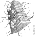
- Fig. 1 discloses a typical prior art automated storage and retrieval system 1 with a framework structure 100 and Fig. 2 and 3 discloses two different prior art container handling vehicles 201,301 suitable for operating on such a system 1.
- the framework structure 100 comprises several upright members 102 and several horizontal members 103 which are supported by the upright members 102.
- the members 102, 103 may typically be made of metal, e.g. extruded aluminium profiles.
- the framework structure 100 defines a storage grid 104 comprising storage columns 105 arranged in rows, in which storage columns 105 storage containers 106, also known as bins, are stacked one on top of another to form stacks 107.
- the storage grid 104 guards against horizontal movement of the stacks 107 of storage containers 106, and guides vertical movement of the containers 106, but does normally not otherwise support the storage containers 106 when stacked.
- the automated storage and retrieval system 1 comprises a rail system 108 arranged in a grid pattern across the top of the storage 104, on which rail system 108 a plurality of container handling vehicles 201, 301 are operated to raise storage containers 106 from, and lower storage containers 106 into, the storage columns 105, and to transport the storage containers 106 above the storage columns 105.
- the rail system 108 comprises a first set of parallel rails 110 arranged to guide movement of the container handling vehicles 201, 301 in a first direction X across the top of the frame structure 100, and a second set of parallel rails 111 arranged perpendicular to the first set of rails 110 to guide movement of the container handling vehicles 201, 301 in a second direction Y which is perpendicular to the first direction X.
- the rail system 108 defines grid columns 115 above which the container handling vehicles 201, 301 can move laterally above the storage columns 105, i.e. in a plane which is parallel to the horizontal X-Y plane.
- Each prior art container handling vehicle 201, 301 comprises a vehicle body 201a, 301a, and first and second sets of wheels 201b, 301b, 201c, 301c which enable the lateral movement of the container handling vehicles 201, 301 in the X direction and in the Y direction, respectively.
- first and second sets of wheels 201b, 301b, 201c, 301c which enable the lateral movement of the container handling vehicles 201, 301 in the X direction and in the Y direction, respectively.
- the first set of wheels 201b, 301b is arranged to engage with two adjacent rails of the first set 110 of rails
- the second set of wheels 201c, 301c is arranged to engage with two adjacent rails of the second set 111 of rails.
- Each set of wheels 201b, 301b, 201c, 301c can be lifted and lowered, so that the first set of wheels 201b, 301b and/or the second set of wheels 201c, 301c can be engaged with the respective set of rails 110, 111 at any one time.
- Each prior art container handling vehicle 201, 301 also comprises a lifting device (not shown) for vertical transportation of storage containers 106, e.g. raising a storage container 106 from, and lowering a storage container 106 into, a storage column 105.
- the lifting device comprises one or more gripping / engaging devices (not shown) which are adapted to engage a storage container 106, and which gripping / engaging devices can be lowered from the vehicle 201, 301 so that the position of the gripping / engaging devices with respect to the vehicle 201, 301 can be adjusted in a third direction Z which is orthogonal the first direction X and the second direction Y.
- Each prior art container handling vehicle 201, 301 comprises a storage compartment or space for receiving and stowing a storage container 106 when transporting the storage container 106 across the rail system 108.
- the storage space may comprise a cavity arranged centrally within the vehicle body 201a as shown in Fig. 2 and as described in e.g. WO2015/193278A1 , the contents of which are incorporated herein by reference.
- Fig. 3 shows an alternative configuration of a container handling vehicle 301 with a cantilever construction.
- a container handling vehicle 301 with a cantilever construction.
- Such a vehicle is described in detail in e.g. NO317366, the contents of which are also incorporated herein by reference.
- the central cavity container handling vehicles 201 shown in Fig. 2 may have a footprint that covers an area with dimensions in the X and Y directions which is generally equal to the lateral extent of a grid column 115, i.e. the extent of a grid column 115 in the X and Y directions, e.g. as is described in WO2015/193278A1 , the contents of which are incorporated herein by reference.
- the term 'lateral' used herein may mean 'horizontal'.
- the central cavity container handling vehicles 101 may have a footprint which is larger than the lateral area defined by a grid column 115, e.g. as is disclosed in WO2014/090684A1 .
- neighbouring grid cells are arranged in contact with each other such that there is no space there-between.
- a grid 104 In a storage grid 104, most of the grid columns 115 are storage columns 105, i.e. grid columns 105 where storage containers 106 are stored in stacks 107.
- a grid 104 normally has at least one grid column 115 which is used not for storing storage containers 106, but which comprises a location where the container handling vehicles 201, 301 can drop off and/or pick up storage containers 106 so that they can be transported to an access station (not shown) where the storage containers 106 can be accessed from outside of the grid 104 or transferred out of or into the grid 104.
- such a location is normally referred to as a 'port' and the grid column 115 in which the port is located may be referred to as a ⁇ port column' 119, 120.
- one of the container handling vehicles 201, 301 is instructed to retrieve the target storage container 106 from its position in the grid 104 and transport it to the drop-off port 119.
- This operation involves moving the container handling vehicle 201, 301 to a grid location above the storage column 105 in which the target storage container 106 is positioned, retrieving the storage container 106 from the storage column 105 using the container handling vehicle's 201, 301 lifting devices (not shown), and transporting the storage container 106 to the drop-off port 119. If the target storage container 106 is located deep within a stack 107, i.e.
- the operation also involves temporarily moving the above-positioned storage containers 106 prior to lifting the target storage container 106 from the storage column 105.
- This step which is sometimes referred to as "digging" within the art, may be performed with the same container handling vehicle that is subsequently used for transporting the target storage container 106 to the drop-off port 119, or with one or a plurality of other cooperating container handling vehicles.
- the automated storage and retrieval system 1 may have container handling vehicles specifically dedicated to the task of temporarily removing storage containers 106 from a storage column 105. Once the target storage container 106 has been removed from the storage column 105, the temporarily removed storage containers 106 can be repositioned into the original storage column 105. However, the removed storage containers 106 may alternatively be relocated to other storage columns.
- one of the container handling vehicles 201, 301 is instructed to pick up the storage container 106 from the pick-up port 120 and transport it to a grid location above the storage column 105 where it is to be stored. After any storage containers 106 positioned at or above the target position within the storage column stack 107 have been removed, the container handling vehicle 201, 301 positions the storage container 106 at the desired position. The removed storage containers 106 may then be lowered back into the storage column 105 or relocated to other storage columns.
- a preferred embodiment of the present invention is defined by a system for power management of an automated storage and retrieval system comprising a plurality container handling vehicles with at least one rechargeable power source for handling containers in a three dimensional underlying storage grid, a charging device for charging the at least one rechargeable power source, a power source for supplying power to the storage and retrieval system, a monitoring system for monitoring energy prices, wherein said monitoring system is configured to continuously update a power manager with energy prices, and the power manager is configured to receive information regarding the level of charge of the rechargeable power sources and current resources in terms of the capacity and usage requirements of the container handling vehicles, and said power manager is configured to adapt a power strategy of the automated storage and retrieval system according to the energy prices.
- the power manager is configured to control charging of the rechargeable power source(s) during periods of low energy cost and to control the stored energy as an additional power source for the storage system during periods of high energy cost and to use a ranking system to decide in which order to charge two or more rechargeable power sources and to control storing of energy.
- the monitoring system monitors present and upcoming energy prices.
- the power source can receive power via locally generated energy from renewable energy sources and/or grid power.
- the ranking system of the power manager is configured to decide to charge the rechargeable power sources with the highest charging level first and to decide to use the rechargeable power sources with the highest charging level as an additional power source first.
- the charging device can be a charging station or a charging robot, and at least one large capacity battery can be used for storing energy during periods of low energy cost.
- a preferred embodiment of the present invention is further defined by a method for power management of an automated storage and retrieval system comprising: a plurality of container handling vehicle, with at least one rechargeable power source for handling containers in a three-dimensional underlying storage grid, a charging device for charging the rechargeable power source of the container handling vehicle, a power source for supplying power to the storage system, a monitoring system for monitoring energy prices, the method comprises the following steps: letting the monitoring system establish external power information by: reading present power consumption, and updating present and upcoming energy cost, letting the monitoring system establish internal power information by: acquiring the current energy state of the automated storage and retrieval system, and estimating the future energy state of the automated storage and retrieval system, letting the power manager update the power strategy of the system according to the external and internal power information.
- the power strategy of the system may be updated by letting the power manager use a ranking system to decide in which order to charge the rechargeable power sources and/or letting the ranking system of the power manager decide to charge the rechargeable power sources with the highest charging level first and/or letting the ranking system of the power manager decide to use the rechargeable power sources with the highest charging level as an additional power source first.
- the rechargeable power sources may be used as an additional power source for the system when the prices are high. This additional power source allows the storage system to store power when prices are low and use the stored power when prices are high.
- a power manager that controls the flow of power to or from the rechargeable power sources, the cost of operating the storage system can be reduced greatly and the problem with the operation cost of an automated storage system can be solved.
- the container handling vehicle rail system 108 allows the container handling vehicles 201 to move horizontally between different grid locations, where each grid location is associated with a grid cell 122.
- the storage grid 104 is shown with a height of eight grid cells 122. It is understood, however, that the storage grid 104 can in principle be of any size.
- the storage grid 104 can be considerably wider and/or longer than disclosed in fig. 1 .
- the grid 104 may have a horizontal extent of more than 700x700 storage columns 105.
- the grid 104 can be considerably deeper than disclosed in fig. 1 .
- the storage grid 104 may be more than twelve grid cells 122 deep, i.e. in the Z direction indicated in Fig. 1 .
- Fig. 2 is a perspective view of a prior art container handling vehicle having a centrally arranged cavity for containing storage containers 106 therein.
- the central cavity container handling vehicles 201 may have a footprint that covers an area with dimensions in the X and Y directions which is generally equal to the lateral extent of a grid column 115, i.e. the extent of a grid column 115 in the X and Y directions, e.g. as is described in WO2015/193278A1 , the contents of which are incorporated herein by reference.
- the central cavity container handling vehicles 101 may have a footprint which is larger than the lateral area defined by a grid column 115, e.g. as is disclosed in WO2014/090684A1 .
- Figure 3 is a perspective view of a prior art container handling vehicle having a cantilever for containing storage containers 106 underneath.
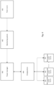
- FIG. 4 is a box drawing of the different modules of the present invention and how they are connected.
- the storage system receives power from at least one power source 401.
- the power source 401 can be either grid power or locally generated power from renewable power sources. Power can further be stored in rechargeable power sources comprised in the system.
- the storage system 1 receives both grid power and locally generated power from renewable power sources. Locally generated power from renewable power sources can be wind power, hydro power, solar power or any other power source that is available.
- the amount of available power and the cost of the power is monitored by a monitoring system 402.
- the monitoring system 402 can receive power information about available power and current cost of power from the grid provider, as well as an estimate of costs of power for an upcoming time period. The upcoming time period may for instance be the next 24 hours or even further ahead in time.
- the monitoring system 402 sends the power information to a power manager 403.
- the power manager 403 controls how the power required for the operation of the system is distributed and how much power should be drawn from the grid power, how much should be drawn from the locally generated power from renewable power sources and/or how much power should be drawn from the power stored in rechargeable power sources of the system.
- the power manager also controls if grid power or power from renewable power sources should be used for charging the rechargeable power sources.
- the power manager 403 is in control of at least one charging device 404,
- the charging device 404 is used to charge at least one rechargeable power source 405.
- rechargeable power sources 405 stored at a plurality of different charging devices 404.
- These rechargeable power sources 405 can be batteries used for powering the container handling vehicles 200, 300.
- the rechargeable power sources 405 can be battery packs, whose sole purpose is to store energy when the conditions are right for the locally generated renewable power sources to produce a surplus of energy and when the prices for grid power are low.
- the charging device 404 can both charge the rechargeable power sources 405 and draw power from the rechargeable power sources 405.
- the power is directed to the charging devices 404 from either the power grid and/or the locally renewable power sources.
- the power manager 403 can control the distribution of the power e.g. that some energy is stored for later use, some energy is used for charging rechargeable power sources 405 of the container handling vehicles 200, 300 and some energy is used to operate the rest of the system.
- the stored power can be directed from the rechargeable power sources 405 via the charging devices 404 to power the rest of the storage system.
- Figure 5 is a flow chart showing the different steps of the method according to a preferred embodiment of the present invention.
- the storage system first retrieves external power information 510. This requires retrieving information of the current energy supply 520 and updating the estimate for the future cost of energy 530.
- the first step is to check if there is locally generated renewable energy available 522.
- the amount of available energy from a locally generated energy source is retrieved 524.
- the next step is to retrieve information of the prices for grid power 526. This can be obtained via e.g. downloading information from the internet.
- the next step is to estimate future energy cost 530. If the system is connected to a locally generated renewable energy source 532 the future energy production from this source is estimated 534. This is done by collecting information like weather data, time of day and which season it is in order to estimate the available amount of future energy from the locally generated renewable energy source. Further, the predicted prices for the future grid energy is retrieved and updated 536.
- the next step is to retrieve internal power information 540.
Landscapes
- Engineering & Computer Science (AREA)
- Power Engineering (AREA)
- Mechanical Engineering (AREA)
- Transportation (AREA)
- Business, Economics & Management (AREA)
- Economics (AREA)
- Health & Medical Sciences (AREA)
- Tourism & Hospitality (AREA)
- Theoretical Computer Science (AREA)
- General Physics & Mathematics (AREA)
- Human Resources & Organizations (AREA)
- Marketing (AREA)
- General Business, Economics & Management (AREA)
- Strategic Management (AREA)
- Physics & Mathematics (AREA)
- Primary Health Care (AREA)
- General Health & Medical Sciences (AREA)
- Water Supply & Treatment (AREA)
- Public Health (AREA)
- Operations Research (AREA)
- Development Economics (AREA)
- Entrepreneurship & Innovation (AREA)
- Quality & Reliability (AREA)
- Charge And Discharge Circuits For Batteries Or The Like (AREA)
- Remote Monitoring And Control Of Power-Distribution Networks (AREA)
- Warehouses Or Storage Devices (AREA)
Abstract
Description
- The present invention concerns a system and a method for power management of an automated storage and retrieval system, and more particularly a system and a method for power management of an automated storage and retrieval system wherein the power management is dependent on the current and upcoming energy prices.
-
Fig. 1 discloses a typical prior art automated storage andretrieval system 1 with aframework structure 100 andFig. 2 and 3 discloses two different prior art container handling vehicles 201,301 suitable for operating on such asystem 1. - The
framework structure 100 comprises severalupright members 102 and severalhorizontal members 103 which are supported by theupright members 102. Themembers - The
framework structure 100 defines astorage grid 104 comprisingstorage columns 105 arranged in rows, in whichstorage columns 105storage containers 106, also known as bins, are stacked one on top of another to formstacks 107. Thestorage grid 104 guards against horizontal movement of thestacks 107 ofstorage containers 106, and guides vertical movement of thecontainers 106, but does normally not otherwise support thestorage containers 106 when stacked. - The automated storage and
retrieval system 1 comprises arail system 108 arranged in a grid pattern across the top of thestorage 104, on which rail system 108 a plurality ofcontainer handling vehicles storage containers 106 from, andlower storage containers 106 into, thestorage columns 105, and to transport thestorage containers 106 above thestorage columns 105. Therail system 108 comprises a first set ofparallel rails 110 arranged to guide movement of thecontainer handling vehicles frame structure 100, and a second set ofparallel rails 111 arranged perpendicular to the first set ofrails 110 to guide movement of thecontainer handling vehicles rail system 108 definesgrid columns 115 above which thecontainer handling vehicles storage columns 105, i.e. in a plane which is parallel to the horizontal X-Y plane. - Each prior art
container handling vehicle container handling vehicles Fig. 2 and 3 two wheels in each set are fully visible. The first set of wheels 201b, 301b is arranged to engage with two adjacent rails of thefirst set 110 of rails, and the second set of wheels 201c, 301c is arranged to engage with two adjacent rails of thesecond set 111 of rails. Each set of wheels 201b, 301b, 201c, 301c can be lifted and lowered, so that the first set of wheels 201b, 301b and/or the second set of wheels 201c, 301c can be engaged with the respective set ofrails - Each prior art
container handling vehicle storage containers 106, e.g. raising astorage container 106 from, and lowering astorage container 106 into, astorage column 105. The lifting device comprises one or more gripping / engaging devices (not shown) which are adapted to engage astorage container 106, and which gripping / engaging devices can be lowered from thevehicle vehicle - Each prior art
container handling vehicle storage container 106 when transporting thestorage container 106 across therail system 108. The storage space may comprise a cavity arranged centrally within the vehicle body 201a as shown inFig. 2 and as described in e.g.WO2015/193278A1 , the contents of which are incorporated herein by reference. -
Fig. 3 shows an alternative configuration of acontainer handling vehicle 301 with a cantilever construction. Such a vehicle is described in detail in e.g. NO317366, the contents of which are also incorporated herein by reference. - The central cavity
container handling vehicles 201 shown inFig. 2 may have a footprint that covers an area with dimensions in the X and Y directions which is generally equal to the lateral extent of agrid column 115, i.e. the extent of agrid column 115 in the X and Y directions, e.g. as is described inWO2015/193278A1 , the contents of which are incorporated herein by reference. The term 'lateral' used herein may mean 'horizontal'. - Alternatively, the central cavity container handling vehicles 101 may have a footprint which is larger than the lateral area defined by a
grid column 115, e.g. as is disclosed inWO2014/090684A1 . - In the X and Y directions, neighbouring grid cells are arranged in contact with each other such that there is no space there-between.
- In a
storage grid 104, most of thegrid columns 115 arestorage columns 105,i.e. grid columns 105 wherestorage containers 106 are stored instacks 107. However, agrid 104 normally has at least onegrid column 115 which is used not for storingstorage containers 106, but which comprises a location where thecontainer handling vehicles storage containers 106 so that they can be transported to an access station (not shown) where thestorage containers 106 can be accessed from outside of thegrid 104 or transferred out of or into thegrid 104. Within the art, such a location is normally referred to as a 'port' and thegrid column 115 in which the port is located may be referred to as a `port column' 119, 120. The transportation to the access station may be in any direction, that is horizontal, tilted and/or vertical. For example, thestorage containers 106 may be placed in a random ordedicated grid column 115 within thestorage grid 104, then picked up by any container handling vehicle and transported to aport storage containers 106 having a general transportation orientation somewhere between horizontal and vertical. - When a
storage container 106 stored in thegrid 104 disclosed inFig. 1 is to be accessed, one of thecontainer handling vehicles target storage container 106 from its position in thegrid 104 and transport it to the drop-off port 119. This operation involves moving thecontainer handling vehicle storage column 105 in which thetarget storage container 106 is positioned, retrieving thestorage container 106 from thestorage column 105 using the container handling vehicle's 201, 301 lifting devices (not shown), and transporting thestorage container 106 to the drop-off port 119. If thetarget storage container 106 is located deep within astack 107, i.e. with one or a plurality ofother storage containers 106 positioned above thetarget storage container 106, the operation also involves temporarily moving the above-positionedstorage containers 106 prior to lifting thetarget storage container 106 from thestorage column 105. This step, which is sometimes referred to as "digging" within the art, may be performed with the same container handling vehicle that is subsequently used for transporting thetarget storage container 106 to the drop-offport 119, or with one or a plurality of other cooperating container handling vehicles. Alternatively, or in addition, the automated storage andretrieval system 1 may have container handling vehicles specifically dedicated to the task of temporarily removingstorage containers 106 from astorage column 105. Once thetarget storage container 106 has been removed from thestorage column 105, the temporarily removedstorage containers 106 can be repositioned into theoriginal storage column 105. However, the removedstorage containers 106 may alternatively be relocated to other storage columns. - When a
storage container 106 is to be stored in thegrid 104, one of thecontainer handling vehicles storage container 106 from the pick-up port 120 and transport it to a grid location above thestorage column 105 where it is to be stored. After anystorage containers 106 positioned at or above the target position within thestorage column stack 107 have been removed, thecontainer handling vehicle storage container 106 at the desired position. The removedstorage containers 106 may then be lowered back into thestorage column 105 or relocated to other storage columns. - For monitoring and controlling the automated storage and
retrieval system 1, e.g. monitoring and controlling the location ofrespective storage containers 106 within thegrid 104, the content of eachstorage container 106; and the movement of thecontainer handling vehicles storage container 106 can be delivered to the desired location at the desired time without thecontainer handling vehicles retrieval system 1 comprises a control system which typically is computerized and which typically comprises a database for keeping track of thestorage containers 106. - In addition to installation, the biggest cost in operating an automated storage system, is the cost of the energy consumed by the container handling vehicles in their daily operations. It is therefore an object of the present invention to reduce this cost.
- The present invention is set forth and characterized in the independent claims, while the dependent claims describe other characteristics of the invention.
- A preferred embodiment of the present invention is defined by a system for power management of an automated storage and retrieval system comprising a plurality container handling vehicles with at least one rechargeable power source for handling containers in a three dimensional underlying storage grid, a charging device for charging the at least one rechargeable power source, a power source for supplying power to the storage and retrieval system, a monitoring system for monitoring energy prices, wherein said monitoring system is configured to continuously update a power manager with energy prices, and the power manager is configured to receive information regarding the level of charge of the rechargeable power sources and current resources in terms of the capacity and usage requirements of the container handling vehicles, and said power manager is configured to adapt a power strategy of the automated storage and retrieval system according to the energy prices.
- Further the power manager is configured to control charging of the rechargeable power source(s) during periods of low energy cost and to control the stored energy as an additional power source for the storage system during periods of high energy cost and to use a ranking system to decide in which order to charge two or more rechargeable power sources and to control storing of energy. The monitoring system monitors present and upcoming energy prices.
- Also, the power source can receive power via locally generated energy from renewable energy sources and/or grid power.
- The ranking system of the power manager is configured to decide to charge the rechargeable power sources with the highest charging level first and to decide to use the rechargeable power sources with the highest charging level as an additional power source first.
- The charging device can be a charging station or a charging robot, and at least one large capacity battery can be used for storing energy during periods of low energy cost.
- A preferred embodiment of the present invention is further defined by a method for power management of an automated storage and retrieval system comprising: a plurality of container handling vehicle, with at least one rechargeable power source for handling containers in a three-dimensional underlying storage grid, a charging device for charging the rechargeable power source of the container handling vehicle, a power source for supplying power to the storage system, a monitoring system for monitoring energy prices, the method comprises the following steps: letting the monitoring system establish external power information by: reading present power consumption, and updating present and upcoming energy cost, letting the monitoring system establish internal power information by: acquiring the current energy state of the automated storage and retrieval system, and estimating the future energy state of the automated storage and retrieval system, letting the power manager update the power strategy of the system according to the external and internal power information.
- The power strategy of the system may be updated by letting the power manager use a ranking system to decide in which order to charge the rechargeable power sources and/or letting the ranking system of the power manager decide to charge the rechargeable power sources with the highest charging level first and/or letting the ranking system of the power manager decide to use the rechargeable power sources with the highest charging level as an additional power source first.
- By letting a power manager control the charging of the rechargeable power sources dependent on the prices of power it is possible to reduce the cost of power in a storage system. The rechargeable power sources may be used as an additional power source for the system when the prices are high. This additional power source allows the storage system to store power when prices are low and use the stored power when prices are high. By incorporating a power manager that controls the flow of power to or from the rechargeable power sources, the cost of operating the storage system can be reduced greatly and the problem with the operation cost of an automated storage system can be solved.
- The following drawings are appended to facilitate the understanding of the invention. The drawings show embodiments of the invention, which will now be described by way of example only, where:
-
Fig. 1 is a perspective view of a priorart storage grid 104 with container handling vehicles running on top. -
Fig. 2 is a perspective view of a prior art container handling vehicle having a centrally arranged cavity for containingstorage containers 106 therein. -
Fig. 3 . is a perspective view of a prior art container handling vehicle having a cantilever for containingstorage containers 106 underneath. -
Fig. 4 is a box drawing of the different modules of the present invention and how they are connected. -
Fig. 5 is a flow chart of the different steps of the method. - In the following, the invention will be discussed in more detail with reference to the appended drawings. It should be understood, however, that the drawings are not intended to limit the invention to the subj ect-matter depicted.
- A typical prior art automated storage and retrieval system 10 with a
framework structure 100 was described in the background section above. - The container handling
vehicle rail system 108 allows thecontainer handling vehicles 201 to move horizontally between different grid locations, where each grid location is associated with agrid cell 122. - In
fig. 1 , thestorage grid 104 is shown with a height of eightgrid cells 122. It is understood, however, that thestorage grid 104 can in principle be of any size. Thestorage grid 104 can be considerably wider and/or longer than disclosed infig. 1 . For example, thegrid 104 may have a horizontal extent of more than700x700 storage columns 105. Also, thegrid 104 can be considerably deeper than disclosed infig. 1 . For example, thestorage grid 104 may be more than twelvegrid cells 122 deep, i.e. in the Z direction indicated inFig. 1 . -
Fig. 2 is a perspective view of a prior art container handling vehicle having a centrally arranged cavity for containingstorage containers 106 therein. - The central cavity
container handling vehicles 201 may have a footprint that covers an area with dimensions in the X and Y directions which is generally equal to the lateral extent of agrid column 115, i.e. the extent of agrid column 115 in the X and Y directions, e.g. as is described inWO2015/193278A1 , the contents of which are incorporated herein by reference. - Alternatively, the central cavity container handling vehicles 101 may have a footprint which is larger than the lateral area defined by a
grid column 115, e.g. as is disclosed inWO2014/090684A1 . -
Figure 3 is a perspective view of a prior art container handling vehicle having a cantilever for containingstorage containers 106 underneath. -
Figure 4 is a box drawing of the different modules of the present invention and how they are connected. The storage system receives power from at least onepower source 401. Thepower source 401 can be either grid power or locally generated power from renewable power sources. Power can further be stored in rechargeable power sources comprised in the system. In a preferred embodiment thestorage system 1 receives both grid power and locally generated power from renewable power sources. Locally generated power from renewable power sources can be wind power, hydro power, solar power or any other power source that is available. The amount of available power and the cost of the power is monitored by amonitoring system 402. Themonitoring system 402 can receive power information about available power and current cost of power from the grid provider, as well as an estimate of costs of power for an upcoming time period. The upcoming time period may for instance be the next 24 hours or even further ahead in time. - The
monitoring system 402 sends the power information to apower manager 403. Thepower manager 403 controls how the power required for the operation of the system is distributed and how much power should be drawn from the grid power, how much should be drawn from the locally generated power from renewable power sources and/or how much power should be drawn from the power stored in rechargeable power sources of the system. The power manager also controls if grid power or power from renewable power sources should be used for charging the rechargeable power sources. - The
power manager 403 is in control of at least onecharging device 404, The chargingdevice 404 is used to charge at least onerechargeable power source 405. - In a preferred solution there is a plurality of
rechargeable power sources 405 stored at a plurality ofdifferent charging devices 404. Theserechargeable power sources 405 can be batteries used for powering thecontainer handling vehicles rechargeable power sources 405 can be battery packs, whose sole purpose is to store energy when the conditions are right for the locally generated renewable power sources to produce a surplus of energy and when the prices for grid power are low. - The charging
device 404 can both charge therechargeable power sources 405 and draw power from therechargeable power sources 405. The power is directed to the chargingdevices 404 from either the power grid and/or the locally renewable power sources. Thepower manager 403 can control the distribution of the power e.g. that some energy is stored for later use, some energy is used for chargingrechargeable power sources 405 of thecontainer handling vehicles - The stored power can be directed from the
rechargeable power sources 405 via the chargingdevices 404 to power the rest of the storage system. -
Figure 5 is a flow chart showing the different steps of the method according to a preferred embodiment of the present invention. - In this embodiment the storage system first retrieves
external power information 510. This requires retrieving information of thecurrent energy supply 520 and updating the estimate for the future cost ofenergy 530. - For obtaining information regarding the
current energy supply 520, the first step is to check if there is locally generated renewable energy available 522. The amount of available energy from a locally generated energy source is retrieved 524. The next step is to retrieve information of the prices forgrid power 526. This can be obtained via e.g. downloading information from the internet. - The next step is to estimate
future energy cost 530. If the system is connected to a locally generatedrenewable energy source 532 the future energy production from this source is estimated 534. This is done by collecting information like weather data, time of day and which season it is in order to estimate the available amount of future energy from the locally generated renewable energy source. Further, the predicted prices for the future grid energy is retrieved and updated 536. - The next step is to retrieve
internal power information 540. - Retrieving the
internal power information 540 comprises the step of calculating the systemscurrent energy state 550. The current energy state can comprise information regarding how much energy that is stored in the system at the current time. Information regarding the current energy consumption of the system is also retrieved. The current consumption depends on how many container handling vehicles are operating, how many rechargeable power sources are charging in the charging devices and how much energy is consumed by the rest of the system, e.g. by the ports, conveyer belts and such. - Retrieving the internal power information also involves the step of updating the estimate for the systems
future energy state 560. This comprises estimation of the energy need for the current and upcoming activities. Further the historical data can be used in order to improve the estimates. The historical data can be used in machine learning and in artificial intelligence in order to improve the accuracy of the estimated future power consumption. - The final step is to update the
power strategy 570. The updating of thepower strategy 570 involves afirst step 580 of updating the retrieved power information, both internal 540 and external 510, and the energy need, and using historical data to optimize the charging strategy of thepower manager 403. - Updating the power strategy finally involves planning the future energy state of the
system 590. If the cost of energy is low, or there is high production of locally generated renewable energy, the power manager will try to increase the stored energy in the system by charging the rechargeable energy sources more often and for a longer period of time. This is planned in relation to the activity of the system where any reduction to operational efficiency is also minimised. - When all steps are done the
power manager 403 starts the process over again and the power manager is hence updated continuously by receiving or retrieving information about the energy prices, charging status of the rechargeable power sources, and the internal and external power information. - In an alternative embodiment of the present invention the charging strategy can be set statically. The batteries can be set to charge at fixed time intervals during the day. Instead of collecting estimated future energy cost, the system can be set up with fixed time intervals wherein it is preferred that the storage system increases its state of charge. This will typically be favorable for businesses with a work shift where the charging of the system is set to a time of day when the energy price is at its lowest (typically evening time or night time). Another time of day when the system can be set to increase its state of charge is during lunch time. Basically, any time when the ordinary work force has a down time, it is a good time for increasing the state of charge.
- The storage of the power can be in the systems internal supply of batteries. These batteries are the ones in the container handling vehicles. They can be fixed in the container handling vehicles, or they can be exchangeable. In an alternative solution at least one large capacity batteries can be used for storing power, when the prices are low. They are hence not a part of the rechargeable power sources that are used to power the container handling vehicles.
-
- 1
- Automated storage and retrieval system
- 100
- framework structure
- 102
- upright members
- 103
- horizontal members
- 104
- storage grid
- 105
- storage columns
- 106
- storage container
- 106'
- storage container
- 107
- stacks
- 108
- rail system
- 110
- a first set of parallel rails
- 111
- a second set of parallel rails
- 115
- grid column
- 119
- port column
- 120
- port column
- 122
- grid cell
- 200
- container handling vehicle
- 201
- container handling vehicle
- 300
- container handling vehicle
- 301
- container handling vehicle
- 401
- power source
- 402
- monitoring system
- 403
- power manager
- 404
- charging device
- 405
- rechargeable power source
- 510
- external power information
- 520
- current energy supply
- 522
- locally generated renewable energy supply
- 524
- available energy
- 526
- price for grid power
- 530
- estimate for future energy cost
- 532
- locally generated renewable energy supply
- 534
- Future energy production
- 536
- predicted energy prices
- 540
- internal power information
- 550
- the systems current energy state
- 560
- estimate for the systems future energy state
- 570
- power strategy
- 580
- Updating power strategy based on energy information, need and historical data
- 590
- future energy state of the system
- The following CLAUSES also form part of the present disclosure.
-
- 1. A system for power management of an automated storage and retrieval system (1) comprising a plurality container handling vehicles (201, 301) with at least one rechargeable power source (405) for handling containers (201, 301) in a three dimensional underlying storage grid (104), a charging device (404) for charging the at least one rechargeable power source (405), a power source (401) for supplying power to the storage and retrieval system (1), a monitoring system (402) for monitoring energy prices,
c h a r act e r i zed in that said monitoring system (402) is configured to continuously update a power manager (403) with energy prices, and the power manager (403) is configured to be updated with information regarding the level of charge of the rechargeable power sources (405) and current resources in terms of the capacity and usage requirements of the container handling vehicles (201, 301), and said power manager (403) is configured to adjust a power strategy of the automated storage and retrieval system (1) according to the energy prices and to control the stored energy as an additional power source for the storage system during periods of high energy cost. - 2. The system according to
clause 1, wherein the power manager (403) is configured to control charging of the rechargeable power source(s) (405) during periods of low energy cost. - 3. The system according to
clause 1 or 2, wherein the monitoring system (402) is configured to monitor present and upcoming energy prices. - 4. The system according to any of the preceding clause, wherein the power source (401) receives power from locally generated renewable energy sources and/or grid power.
- 5. The system according to any of the preceding clauses, wherein the power manager (403) is configured to use a ranking system to decide in which order to charge two or more rechargeable power sources (405).
- 6. The system according to clause 5, wherein the ranking system of the power manager (403) is configured to decide to charge the rechargeable power sources (405) with the highest charging level first.
- 7. The system according to clauses 5 or 6, wherein the ranking system of the power manager (403) is configured to decide to use the rechargeable power sources (405) with the highest charging level as an additional power source first.
- 8. The system according to any of the preceding clauses, wherein the power manager (403) is configured to control storing of energy if the future energy prices are lower than the average energy price of a preceding time period.
- 9. The system according to any of the preceding clauses wherein energy from local renewable energy sources are used to store energy if the future energy prices are lower than the average energy price of a preceding time period.
- 10. The system according to clause 9, wherein energy from local renewable energy sources are used as an additional energy source for the storage system if the future energy prices are higher than the average energy price of a preceding time period.
- 11. The system according to clauses 8-10, wherein a preceding time period can be the preceding month.
- 12. The system according to any of the preceding clauses, wherein the charging device (404) is a charging station or a charging robot.
- 13. The system according to any of the preceding clauses, wherein at least one large capacity battery is used for storing energy during periods of low energy cost.
- 14. A method for power management of an automated storage and retrieval system (1) comprising: a plurality of container handling vehicles (201, 301), with at least one rechargeable power source (405) for handling containers in a three-dimensional underlying storage grid (104), a charging device (404) for charging the rechargeable power sources of the container handling vehicles (201, 301), a power source (401) for supplying power to the storage system (1), a monitoring system (402) for monitoring energy prices, the method comprises the following steps:
- letting the monitoring system (402) establish external power information by:
- reading present power consumption, and
- updating present and upcoming energy cost,
- letting the monitoring system (402) establish internal power information by:
- acquiring the current energy state of the automated storage and retrieval system, and
- estimating the future energy state of the automated storage and retrieval system,
- letting the power manager (403) update the power strategy of the system according to the external and internal power information,
- letting the power manager (403) control use of stored energy of the rechargeable power sources (405) as an additional power source for the storage system during periods of high energy cost.
- letting the monitoring system (402) establish external power information by:
- 15. The method according to clause 14, wherein the power strategy is updated by letting the power manager (403) control charging of the rechargeable power sources (405).
- 16. The method according to any of clause 14-15, wherein the power strategy is updated by letting the power source (401) receive power from locally generated renewable energy sources and/or grid power.
- 17. The method according to any of clauses 14-16, wherein the power strategy is updated by letting the power manager (403) use a ranking system to decide in which order to charge the rechargeable power sources.
- 18. The method according to any of clauses 14-17, wherein the power strategy is updated by letting the ranking system of the power manager (403) decide to charge the rechargeable power sources (405) with the highest charging level first.
- 19. The method according to any of clauses 14-18, wherein the power strategy is updated by letting the ranking system of the power manager (403) decide to use the rechargeable power sources (405) with the highest charging level as an additional power source first.
- 20. The method according to any of clauses 14-19, wherein the power strategy is updated by letting the power manager (403) control storing of energy if the future energy prices are lower than the average energy price of a preceding time period.
- 21. The method according to any of clauses 14-20, wherein the power strategy is updated by letting energy from local renewable energy sources be used to store energy if the future energy prices are lower than the average energy price of a preceding time-period.
- 22. The method according to any of clauses 14-21, wherein the power strategy is updated by letting energy from local renewable energy sources be used as an additional energy source for the storage system if the future energy prices are higher than the average energy price of a preceding time-period.
- 23. The method according to clauses 14-22, wherein a preceding time-period is the preceding month.
Claims (15)
- A system for power management of an automated storage and retrieval system (1) comprisinga plurality of container handling vehicles (201, 301) for handling containers in a framework structure (100),at least one exchangeable and rechargeable power source (405),a charging device (404) for charging or drawing power from the at least one exchangeable and rechargeable power source (405), anda power manager (403), characterized in that:the power manager (403) is configured to be updated with information regarding the level of charge of the at least one exchangeable and rechargeable power source (405) and current resources in terms of the capacity and usage requirements of the container handling vehicles (201,301),and said power manager (403) is configured to control the stored energy from the at least one exchangeable and rechargeable power source (405) via the charging device (404) as an additional power source for the automated storage and retrieval system (1).
- The system according to claim 1, further comprising
a power source (401) for supplying power to the automated storage and retrieval system (1) and to the charging device (404), and optionally wherein the power source (401) receives power from locally generated renewable energy sources and grid power. - The system according to claim 2, wherein the power manager (403) is configured to control the stored energy from the at least one exchangeable and rechargeable power source (405) via the charging device (404) as an additional power source for the automated storage and retrieval system during periods of low production of locally generated renewable energy and/or high energy cost.
- The system according to claim 2 or claim 3, wherein the power manager (403) is configured to control the stored energy to the at least one exchangeable and rechargeable power source (405) via the charging device (404) to charge the at least one exchangeable and rechargeable power source during periods of high production of locally generated renewable energy and/or low energy cost
- The system according to any preceding claim, further comprising
a monitoring system (402) for monitoring energy prices,
said monitoring system (402) being configured to continuously update the power manager (403) with energy prices, and optionally wherein the monitoring system (402) is configured to monitor present and upcoming energy prices. - The system according to any of the preceding claims, wherein the power manager (403) is configured to use a ranking system to decide in which order to charge two or more rechargeable power sources (405), and optionally wherein the ranking system of the power manager (403) is configured to decide to charge the rechargeable power source (405) with the highest charging level first.
- The system according to any of the preceding claims, wherein the power manager (403) is configured to control storing of energy if the future energy prices are lower than the average energy price of a preceding time period.
- The system according to any of the preceding claims, wherein energy from local renewable energy sources is used to store energy if the future energy prices are lower than the average energy price of a preceding time period, or wherein energy from local renewable energy sources is used as an additional power source for the storage system if the future energy prices are higher than the average energy price of a preceding time period.
- A method for power management of an automated storage and retrieval system (1) comprising: a plurality of container handling vehicles (201, 301) for handling containers in a framework structure (100), at least one exchangeable and rechargeable power source (405), a charging device (404) for charging or drawing power from the at least one exchangeable and rechargeable power source (405), and a power manager (403), the method comprising the following steps:receiving, at the power manager, information regarding the level of charge of the at least one exchangeable and rechargeable power source and current resources in terms of the capacity and usage requirements of the container handling vehicles, andcontrolling, by the power manager, the stored energy from the at least one exchangeable and rechargeable power source via the charging device as an additional power source for the automated storage and retrieval system.
- The method according to claim 9, wherein the system further comprises a power source for supplying power to the automated storage and retrieval system and to the charging device, the method further comprising:receiving, by the power source, power from locally generated renewable energy sources and from grid power, and optionally the method further comprisingcontrolling, by the power manager, the stored energy from the at least one exchangeable and rechargeable power source (405) via the charging device (404) as an additional power source for the automated storage and retrieval system during periods of low production of locally generated renewable energy and/or high energy cost, and further optionally the method further comprising
controlling, by the power manager, the stored energy to the at least one exchangeable and rechargeable power source (405) via the charging device (404) to charge the at least one exchangeable and rechargeable power source during periods of high production of locally generated renewable energy and/or low energy cost. - The method according to claim 10, further comprising receiving energy prices by the power manager and from a monitoring system, the energy prices comprising present and/or upcoming energy prices.
- The method according to claim 10 or claim 11, comprising charging two or more rechargeable power sources in order according to a ranking system, and optionally wherein charging the two or more rechargeable power sources comprises charging the rechargeable power source with a highest level of charge first.
- The method according to any of claims 10 to 12, comprising drawing power from two or more rechargeable power sources in order according to a ranking system, and optionally wherein drawing power from the two or more rechargeable power sources comprises drawing power from the rechargeable power source with a highest level of charge first.
- The method according to any of claims 10 to 13, comprising storing energy by charging the at least one exchangeable and rechargeable power source from a local renewable energy source when the future energy prices are lower than the average energy price of a preceding time period, or the method comprising using energy from local renewable energy sources as an additional power source for the storage system when the future energy prices are higher than the average energy price of a preceding time period.
- A computer-readable medium storing instructions that when executed by a processor cause the processor to carry out the method according to any of claims 10 to 14.
Applications Claiming Priority (3)
| Application Number | Priority Date | Filing Date | Title |
|---|---|---|---|
| NO20191163A NO345589B1 (en) | 2019-09-26 | 2019-09-26 | System and method for power management |
| PCT/EP2020/076340 WO2021058442A1 (en) | 2019-09-26 | 2020-09-21 | System and method for power management |
| EP20775864.0A EP4034419B1 (en) | 2019-09-26 | 2020-09-21 | System and method for power management |
Related Parent Applications (1)
| Application Number | Title | Priority Date | Filing Date |
|---|---|---|---|
| EP20775864.0A Division EP4034419B1 (en) | 2019-09-26 | 2020-09-21 | System and method for power management |
Publications (2)
| Publication Number | Publication Date |
|---|---|
| EP4484213A2 true EP4484213A2 (en) | 2025-01-01 |
| EP4484213A3 EP4484213A3 (en) | 2025-07-02 |
Family
ID=72613927
Family Applications (2)
| Application Number | Title | Priority Date | Filing Date |
|---|---|---|---|
| EP24199340.1A Pending EP4484213A3 (en) | 2019-09-26 | 2020-09-21 | System and method for power management |
| EP20775864.0A Active EP4034419B1 (en) | 2019-09-26 | 2020-09-21 | System and method for power management |
Family Applications After (1)
| Application Number | Title | Priority Date | Filing Date |
|---|---|---|---|
| EP20775864.0A Active EP4034419B1 (en) | 2019-09-26 | 2020-09-21 | System and method for power management |
Country Status (10)
| Country | Link |
|---|---|
| US (2) | US12286027B2 (en) |
| EP (2) | EP4484213A3 (en) |
| JP (1) | JP2022549686A (en) |
| KR (1) | KR102902193B1 (en) |
| CN (2) | CN114450190B (en) |
| CA (1) | CA3151951A1 (en) |
| ES (1) | ES2991056T3 (en) |
| NO (1) | NO345589B1 (en) |
| PL (1) | PL4034419T3 (en) |
| WO (1) | WO2021058442A1 (en) |
Families Citing this family (5)
| Publication number | Priority date | Publication date | Assignee | Title |
|---|---|---|---|---|
| AU2019218868B2 (en) | 2018-02-08 | 2022-01-20 | Walmart Apollo, Llc | Opportunistic charging system for an automated storage and retrieval system |
| JP7600263B2 (en) * | 2020-04-24 | 2024-12-16 | オカド・イノベーション・リミテッド | Energy storage systems for load handling equipment. |
| GB2619064A (en) * | 2022-05-26 | 2023-11-29 | Ocado Innovation Ltd | A combined power and data unit for a storage and retreival system, and related devices |
| FR3139810B1 (en) | 2022-09-20 | 2025-10-10 | Exotec | Method and system for energy management in an automated storage and retrieval system |
| DE102022126609A1 (en) * | 2022-10-12 | 2024-04-18 | Bayerische Motoren Werke Aktiengesellschaft | Charging an electric vehicle at a charging point on a property |
Citations (3)
| Publication number | Priority date | Publication date | Assignee | Title |
|---|---|---|---|---|
| NO317366B1 (en) | 1999-07-01 | 2004-10-18 | Autostore As | Storage system with remote controlled wagons with two wheelsets and lifting device for operation on rails arranged in cross over columns of storage units separated by vertical profile posts |
| WO2014090684A1 (en) | 2012-12-10 | 2014-06-19 | Jakob Hatteland Logistics As | Robot for transporting storage bins |
| WO2015193278A1 (en) | 2014-06-19 | 2015-12-23 | Jakob Hatteland Logistics As | Robot for transporting storage bins |
Family Cites Families (24)
| Publication number | Priority date | Publication date | Assignee | Title |
|---|---|---|---|---|
| JPH09124106A (en) * | 1995-11-02 | 1997-05-13 | Daifuku Co Ltd | Automated warehouse facility |
| US7256516B2 (en) | 2000-06-14 | 2007-08-14 | Aerovironment Inc. | Battery charging system and method |
| US20100017045A1 (en) * | 2007-11-30 | 2010-01-21 | Johnson Controls Technology Company | Electrical demand response using energy storage in vehicles and buildings |
| US20100292855A1 (en) * | 2009-05-14 | 2010-11-18 | Michael Kintner-Meyer | Battery Charging Control Methods, Electrical Vehicle Charging Methods, Battery Charging Control Apparatus, and Electrical Vehicles |
| DE102009046422A1 (en) * | 2009-11-05 | 2011-05-12 | Daniel Schneider | Charging system for electric vehicles |
| KR101132948B1 (en) * | 2010-05-13 | 2012-04-05 | 엘에스산전 주식회사 | System, Apparatus and Method for Charge and Discharge Control of Electric Vehicle |
| JP2012075247A (en) * | 2010-09-28 | 2012-04-12 | Kddi Corp | Control program, charge optimization controller and parking lot system |
| WO2012056516A1 (en) * | 2010-10-26 | 2012-05-03 | トヨタ自動車株式会社 | Power supply device, vehicle provided with same, and power supply method |
| JP6125843B2 (en) * | 2013-01-18 | 2017-05-10 | 京セラ株式会社 | Power control apparatus, power control system, and power control method |
| KR101528079B1 (en) * | 2013-12-27 | 2015-06-10 | 두산중공업 주식회사 | Battery exchange station and operating method for battery exchange station |
| NO340313B1 (en) * | 2014-01-08 | 2017-03-27 | Jakob Hatteland Logistics As | Remote controlled vehicle for picking up storage containers from a storage system, storage system for storage of containers and method for replacing a power source |
| WO2015129301A1 (en) * | 2014-02-26 | 2015-09-03 | 日本電気株式会社 | Microgrid system and control method for same |
| US10017068B2 (en) * | 2014-06-19 | 2018-07-10 | Proterra Inc. | Charging of a fleet of electric vehicles |
| NO340577B1 (en) * | 2015-09-04 | 2017-05-15 | Jakob Hatteland Logistics As | Method for fetching a target bin stored in a storage system and a storage system which includes a control device operating in accordance with the method |
| JP7163001B2 (en) * | 2016-03-03 | 2022-10-31 | 三菱重工業株式会社 | POWER MANAGEMENT DEVICE, POWER MANAGEMENT METHOD, AND LOGISTICS NETWORK SYSTEM |
| US10011183B2 (en) * | 2016-03-09 | 2018-07-03 | Toyota Jidosha Kabushiki Kaisha | Optimized charging and discharging of a plug-in electric vehicle |
| US10454277B2 (en) * | 2016-06-08 | 2019-10-22 | Faith Technologies, Inc. | Method and apparatus for controlling power flow in a hybrid power system |
| NO344308B1 (en) * | 2016-06-21 | 2019-10-28 | Autostore Tech As | Storage system comprising a charging station assembly and method of replacing the power source of a remotely operated vehicle |
| CN205970910U (en) * | 2016-08-25 | 2017-02-22 | 上海蔚来汽车有限公司 | Compact distributing type is filled and is traded accumulate station |
| CN106773715B (en) * | 2017-01-19 | 2023-08-01 | 上海定势能源有限公司 | Energy storage operation control method and system based on electric power spot price prediction and tracking |
| DE112017008213B4 (en) * | 2017-12-18 | 2025-12-11 | Ford Global Technologies, Llc | Method and system for charging vehicles |
| WO2019126806A1 (en) * | 2017-12-22 | 2019-06-27 | The Regents Of The University Of California | Design and control of electric vehicle charging infrastructure |
| CN109685554A (en) * | 2018-12-13 | 2019-04-26 | 江苏中科瀚星数据科技有限公司 | A kind of residential block electric automobile charging pile operation mode |
| EP3767559B1 (en) * | 2019-07-14 | 2023-11-15 | IMEC vzw | Multi-scale optimization framework for smart energy systems |
-
2019
- 2019-09-26 NO NO20191163A patent/NO345589B1/en unknown
-
2020
- 2020-09-21 CN CN202080067348.6A patent/CN114450190B/en active Active
- 2020-09-21 WO PCT/EP2020/076340 patent/WO2021058442A1/en not_active Ceased
- 2020-09-21 ES ES20775864T patent/ES2991056T3/en active Active
- 2020-09-21 PL PL20775864.0T patent/PL4034419T3/en unknown
- 2020-09-21 CA CA3151951A patent/CA3151951A1/en active Pending
- 2020-09-21 US US17/754,182 patent/US12286027B2/en active Active
- 2020-09-21 JP JP2022519212A patent/JP2022549686A/en active Pending
- 2020-09-21 EP EP24199340.1A patent/EP4484213A3/en active Pending
- 2020-09-21 KR KR1020227013368A patent/KR102902193B1/en active Active
- 2020-09-21 EP EP20775864.0A patent/EP4034419B1/en active Active
- 2020-09-21 CN CN202410618294.8A patent/CN118560326A/en active Pending
-
2025
- 2025-02-27 US US19/065,994 patent/US20250242711A1/en active Pending
Patent Citations (3)
| Publication number | Priority date | Publication date | Assignee | Title |
|---|---|---|---|---|
| NO317366B1 (en) | 1999-07-01 | 2004-10-18 | Autostore As | Storage system with remote controlled wagons with two wheelsets and lifting device for operation on rails arranged in cross over columns of storage units separated by vertical profile posts |
| WO2014090684A1 (en) | 2012-12-10 | 2014-06-19 | Jakob Hatteland Logistics As | Robot for transporting storage bins |
| WO2015193278A1 (en) | 2014-06-19 | 2015-12-23 | Jakob Hatteland Logistics As | Robot for transporting storage bins |
Also Published As
| Publication number | Publication date |
|---|---|
| JP2022549686A (en) | 2022-11-28 |
| US20250242711A1 (en) | 2025-07-31 |
| NO20191163A1 (en) | 2021-03-29 |
| WO2021058442A1 (en) | 2021-04-01 |
| EP4034419C0 (en) | 2024-09-11 |
| NO345589B1 (en) | 2021-05-03 |
| EP4034419B1 (en) | 2024-09-11 |
| CN118560326A (en) | 2024-08-30 |
| CN114450190A (en) | 2022-05-06 |
| ES2991056T3 (en) | 2024-12-02 |
| EP4484213A3 (en) | 2025-07-02 |
| CN114450190B (en) | 2024-05-14 |
| US12286027B2 (en) | 2025-04-29 |
| PL4034419T3 (en) | 2025-02-10 |
| EP4034419A1 (en) | 2022-08-03 |
| US20220289063A1 (en) | 2022-09-15 |
| KR102902193B1 (en) | 2025-12-23 |
| KR20220069984A (en) | 2022-05-27 |
| CA3151951A1 (en) | 2021-04-01 |
Similar Documents
| Publication | Publication Date | Title |
|---|---|---|
| US12286027B2 (en) | System and method for power management | |
| US11572231B2 (en) | Storage system with modular container handling vehicles | |
| US12296718B2 (en) | System and a method for harvesting energy from a container handling vehicle | |
| EP3949068B1 (en) | Dynamic power management | |
| HK40114627A (en) | System and method for power management | |
| CN115783580A (en) | Automatic access system and method and automatic stereoscopic warehouse | |
| HK40071278A (en) | System and method for power management | |
| HK40071278B (en) | System and method for power management | |
| US20250058648A1 (en) | An automated storage and retrieval system and a method of operating such an automated storage and retrieval system | |
| US20250236458A1 (en) | Dynamic tuning of dig-down | |
| CN121511200A (en) | Transport device for automated storage and retrieval systems | |
| CN121464063A (en) | Charging a container handling vehicle operating on an automated storage and retrieval system | |
| HK40060631B (en) | Dynamic power management | |
| HK40060631A (en) | Dynamic power management |
Legal Events
| Date | Code | Title | Description |
|---|---|---|---|
| PUAI | Public reference made under article 153(3) epc to a published international application that has entered the european phase |
Free format text: ORIGINAL CODE: 0009012 |
|
| STAA | Information on the status of an ep patent application or granted ep patent |
Free format text: STATUS: THE APPLICATION HAS BEEN PUBLISHED |
|
| STAA | Information on the status of an ep patent application or granted ep patent |
Free format text: STATUS: REQUEST FOR EXAMINATION WAS MADE |
|
| AC | Divisional application: reference to earlier application |
Ref document number: 4034419 Country of ref document: EP Kind code of ref document: P |
|
| AK | Designated contracting states |
Kind code of ref document: A2 Designated state(s): AL AT BE BG CH CY CZ DE DK EE ES FI FR GB GR HR HU IE IS IT LI LT LU LV MC MK MT NL NO PL PT RO RS SE SI SK SM TR |
|
| 17P | Request for examination filed |
Effective date: 20241210 |
|
| REG | Reference to a national code |
Ref country code: HK Ref legal event code: DE Ref document number: 40114627 Country of ref document: HK |
|
| REG | Reference to a national code |
Ref country code: DE Ref legal event code: R079 Free format text: PREVIOUS MAIN CLASS: B60L0053530000 Ipc: B60L0053640000 |
|
| PUAL | Search report despatched |
Free format text: ORIGINAL CODE: 0009013 |
|
| AK | Designated contracting states |
Kind code of ref document: A3 Designated state(s): AL AT BE BG CH CY CZ DE DK EE ES FI FR GB GR HR HU IE IS IT LI LT LU LV MC MK MT NL NO PL PT RO RS SE SI SK SM TR |
|
| RIC1 | Information provided on ipc code assigned before grant |
Ipc: B60L 53/53 20190101ALI20250526BHEP Ipc: B60L 53/80 20190101ALI20250526BHEP Ipc: H02J 3/00 20060101ALI20250526BHEP Ipc: B65G 54/02 20060101ALI20250526BHEP Ipc: B60L 53/64 20190101AFI20250526BHEP |
|
| RAP3 | Party data changed (applicant data changed or rights of an application transferred) |
Owner name: AUTOSTORE TECHNOLOGY AS |
|
| STAA | Information on the status of an ep patent application or granted ep patent |
Free format text: STATUS: THE APPLICATION IS DEEMED TO BE WITHDRAWN |