EP4484198A1 - Working machine - Google Patents
Working machine Download PDFInfo
- Publication number
- EP4484198A1 EP4484198A1 EP24182546.2A EP24182546A EP4484198A1 EP 4484198 A1 EP4484198 A1 EP 4484198A1 EP 24182546 A EP24182546 A EP 24182546A EP 4484198 A1 EP4484198 A1 EP 4484198A1
- Authority
- EP
- European Patent Office
- Prior art keywords
- tubular portion
- elastic member
- working machine
- tank
- fixing piece
- Prior art date
- Legal status (The legal status is an assumption and is not a legal conclusion. Google has not performed a legal analysis and makes no representation as to the accuracy of the status listed.)
- Granted
Links
Images







Classifications
-
- B—PERFORMING OPERATIONS; TRANSPORTING
- B60—VEHICLES IN GENERAL
- B60K—ARRANGEMENT OR MOUNTING OF PROPULSION UNITS OR OF TRANSMISSIONS IN VEHICLES; ARRANGEMENT OR MOUNTING OF PLURAL DIVERSE PRIME-MOVERS IN VEHICLES; AUXILIARY DRIVES FOR VEHICLES; INSTRUMENTATION OR DASHBOARDS FOR VEHICLES; ARRANGEMENTS IN CONNECTION WITH COOLING, AIR INTAKE, GAS EXHAUST OR FUEL SUPPLY OF PROPULSION UNITS IN VEHICLES
- B60K15/00—Arrangement in connection with fuel supply of combustion engines or other fuel consuming energy converters, e.g. fuel cells; Mounting or construction of fuel tanks
- B60K15/03—Fuel tanks
-
- E—FIXED CONSTRUCTIONS
- E02—HYDRAULIC ENGINEERING; FOUNDATIONS; SOIL SHIFTING
- E02F—DREDGING; SOIL-SHIFTING
- E02F9/00—Component parts of dredgers or soil-shifting machines, not restricted to one of the kinds covered by groups E02F3/00 - E02F7/00
- E02F9/08—Superstructures; Supports for superstructures
- E02F9/0858—Arrangement of component parts installed on superstructures not otherwise provided for, e.g. electric components, fenders, air-conditioning units
- E02F9/0883—Tanks, e.g. oil tank, urea tank, fuel tank
-
- B—PERFORMING OPERATIONS; TRANSPORTING
- B60—VEHICLES IN GENERAL
- B60K—ARRANGEMENT OR MOUNTING OF PROPULSION UNITS OR OF TRANSMISSIONS IN VEHICLES; ARRANGEMENT OR MOUNTING OF PLURAL DIVERSE PRIME-MOVERS IN VEHICLES; AUXILIARY DRIVES FOR VEHICLES; INSTRUMENTATION OR DASHBOARDS FOR VEHICLES; ARRANGEMENTS IN CONNECTION WITH COOLING, AIR INTAKE, GAS EXHAUST OR FUEL SUPPLY OF PROPULSION UNITS IN VEHICLES
- B60K15/00—Arrangement in connection with fuel supply of combustion engines or other fuel consuming energy converters, e.g. fuel cells; Mounting or construction of fuel tanks
- B60K15/03—Fuel tanks
- B60K15/04—Tank inlets
-
- B—PERFORMING OPERATIONS; TRANSPORTING
- B60—VEHICLES IN GENERAL
- B60K—ARRANGEMENT OR MOUNTING OF PROPULSION UNITS OR OF TRANSMISSIONS IN VEHICLES; ARRANGEMENT OR MOUNTING OF PLURAL DIVERSE PRIME-MOVERS IN VEHICLES; AUXILIARY DRIVES FOR VEHICLES; INSTRUMENTATION OR DASHBOARDS FOR VEHICLES; ARRANGEMENTS IN CONNECTION WITH COOLING, AIR INTAKE, GAS EXHAUST OR FUEL SUPPLY OF PROPULSION UNITS IN VEHICLES
- B60K15/00—Arrangement in connection with fuel supply of combustion engines or other fuel consuming energy converters, e.g. fuel cells; Mounting or construction of fuel tanks
- B60K15/03—Fuel tanks
- B60K15/063—Arrangement of tanks
- B60K15/067—Mounting of tanks
-
- B—PERFORMING OPERATIONS; TRANSPORTING
- B60—VEHICLES IN GENERAL
- B60Y—INDEXING SCHEME RELATING TO ASPECTS CROSS-CUTTING VEHICLE TECHNOLOGY
- B60Y2200/00—Type of vehicle
- B60Y2200/40—Special vehicles
- B60Y2200/41—Construction vehicles, e.g. graders, excavators
Definitions
- the present invention relates to a working machine including a tank that stores a liquid such as fuel.
- a working machine disclosed in Japanese Unexamined Patent Application Publication No. 2021-185306 is known.
- the working machine disclosed in Japanese Unexamined Patent Application Publication No. 2021-185306 includes a fuel tank that stores fuel to be supplied to a prime mover.
- the fuel tank is provided with a tubular portion protruding in a direction inclined obliquely upward from an outer surface of the tank, and an oil supply opening at a distal end of the tubular portion.
- an object of the present invention is to easily fix a tank including a tubular portion protruding from a tank body in an inclined direction, to a machine body.
- a working machine includes a machine body; a tank including a tank body to store a liquid, and a tubular portion protruding from an outer surface of the tank body in a protruding direction inclined with respect to the outer surface; a fixing piece having a through hole through which the tubular portion is inserted, to fix the tank to the machine body; and an elastic member sandwiched between the fixing piece and the tubular portion.
- the tubular portion has one end connected to the tank body and another end defining a liquid supply opening.
- the elastic member is fitted on the tubular portion in a state of being substantially parallel to the outer surface and non-perpendicular to the protruding direction of the tubular portion.
- the fixing piece is fitted on the elastic member fitted on the tubular portion, substantially in parallel to the outer surface, and is fixed to the machine body.
- the tank including the tubular portion protruding from the tank body in the inclined direction can be easily fixed to the machine body.
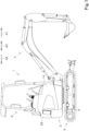
- FIG. 1 is a side view illustrating an overall configuration of a working machine 1 according to the present embodiment.
- FIG. 2 is a perspective view illustrating the overall configuration of the working machine 1 according to the present embodiment.
- an arrow A1 direction in FIG. 1 is referred to as a forward side
- an arrow A2 direction in FIG. 1 is referred to as a rearward side
- an arrow A3 direction in FIG. 1 is referred to as a front-rear direction.
- a near side in FIG. 1 is referred to as a rightward side
- a far side in FIG. 1 is referred to as a leftward side.
- a horizontal direction that is a direction orthogonal to the front-rear direction A3 is described as a width direction.
- the working machine 1 of the present embodiment includes a machine body 2, a traveling device 3 that supports the machine body 2 so as to be capable of traveling, a prime mover 91 (see FIG. 3 ), and a working device 4.
- the prime mover 91 drives a hydraulic pump 95 (described later), and the traveling device 3 and the working device 4 are driven with hydraulic pressure supplied from the hydraulic pump 95.
- the working machine 1 includes, in addition to the prime mover 91, a weight 25 for balancing the weight with the working device 4, a cabin that houses an operator's seat 6, and the like, and the machine body 2 supports mounted objects such as the prime mover 91, the weight 25, and the cabin.
- the machine body 2 includes a frame to which the traveling device 3 is coupled, a turning bearing fixed to the frame, and a turning base plate 5 rotatably (turnably) attached to the frame via the turning bearing, and the operator's seat 6 (cabin), the weight 25, and the like are disposed on the turning base plate 5.
- the working machine 1 includes a cover 14 that covers the prime mover 91, the weight 25, and the like. That is, the mounted objects such as the weight 25 are covered with the cover (hereinafter, referred to as an exterior cover) 14.
- the traveling device 3 is a crawler travel device (endless belt traveling device).
- the prime mover 91 is an internal combustion engine (engine). Accordingly, as illustrated in FIG. 3 , the working machine 1 includes a tank (hereinafter, referred to as a fuel tank) 130 that stores fuel to be supplied to the prime mover 91.
- the prime mover 91 is mounted in a center portion in the width direction of a rear portion of the machine body 2.
- the prime mover 91 is disposed below the operator's seat 6.
- a radiator 92, an oil cooler 93, a hydraulic pump 95, and a cooling fan 100 are disposed both leftward and rightward of the prime mover 91.
- a right portion of the exterior cover 14 extends to protrude forward to the vicinity of a right front end of the machine body 2.
- the fuel tank 130 and a hydraulic fluid tank 150 are disposed inside the right portion of the exterior cover 14.
- a door 154 with a locking function that enables access to the fuel tank 130 during refueling or the like is provided in an outer side surface of the right portion of the exterior cover 14.
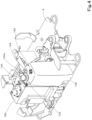
- the fuel tank 130 stores fuel such as light oil or gasoline. As illustrated in FIG. 4 , the fuel tank 130 is disposed on the turning base plate 5 that is a portion of the machine body 2. Although details will be described later, in the present embodiment, the fuel tank 130 is fixed in a state of being supported by the turning base plate 5.
- the fuel tank 130 includes a tank body 131 that stores a liquid, and a tubular portion 132 protruding in a protruding direction inclined with respect to an outer surface 131a of the tank body 131.
- the working machine 1 includes, as means for fixing the fuel tank 130, a fixing piece 133 that has a through hole 149 through which the tubular portion 132 is inserted and fixes the fuel tank 130 to the machine body 2, and an elastic member 145 sandwiched between the fixing piece 133 and the tubular portion 132.
- the fuel tank 130 is disposed with the outer surface 131a of the tank body 131 facing upward.
- the tank body 131 is formed to have one direction in a longitudinal direction.
- the tank body 131 is disposed to have the one direction in a vertical direction. That is, the tank body 131 is a vertically long container that stores a liquid, and is formed of synthetic resin or the like.
- the tank body 131 is hollow and stores liquid fuel.
- the tank body 131 is disposed in an upright state on the turning base plate 5.
- a planar portion 131a is included in one surface in one direction of outer surfaces of the tank body 131. That is, the planar portion 131a is included in an upper surface that is the one surface in the up-down direction of the outer surfaces of the tank body 131.
- the tubular portion 132 has one end connected to the tank body 131 and another end defining a liquid supply opening 135.
- the tubular portion 132 protrudes from the outer surface 131a of the tank body 131.
- the tubular portion 132 protrudes in the protruding direction inclined with respect to the planar portion 131a of the upper surface that is the outer surface of the tank body 131.
- the protruding direction is an outward side of the machine body 2 with respect to a vertically upward side.
- the upper surface of the tank body 131 is "an outer surface 131a from which the tubular portion 132 protrudes (an outer surface 131a to which a proximal end of the tubular portion 132 is connected)".
- the upper surface (the outer surface facing upward) of the tank body 131 has a high portion and a low portion, and the high portion is the planar portion 131a.
- the tubular portion 132 protrudes from the planar portion 131a at the high portion of the upper surface of the tank body 131 having the high portion and the low portion, and liquid level sensors 153 and 134 are provided at the low portion around the planar portion 131a.
- the tubular portion 132 is disposed at a position shifted from a center portion of the upper surface of the tank body 131.
- the tubular portion 132 (planar portion 131a) is positioned at a substantially center portion near one side surface of a peripheral wall of the tank body 131.
- the one side surface of the peripheral wall of the tank body 131 is located in a backward direction of the traveling device 3, and accordingly, the tubular portion 132 (planar portion 131a) is disposed at a center portion in the left-right direction of a rear portion of the upper surface. Accordingly, the liquid level sensor 153 is disposed at a front portion of the upper surface of the tank body 131 (forward of the tubular portion 132), and the liquid level sensor 134 is disposed at a lateral portion of the upper surface of the tank body 131 (beside the tubular portion 132: leftward in the present embodiment).
- the liquid level sensor 153 detects the liquid level of the liquid stored in the tank body 131 using a float, and displays the amount of liquid in the tank using a needle that moves in association with the float.
- the liquid level sensor 134 detects the liquid level in the tank and sends a signal corresponding to the detection result to a controller (not illustrated).
- the amount of liquid corresponding to the detection result of the liquid level sensor 134 is displayed on a meter panel (not illustrated).
- the tubular portion 132 will be described in more detail. As illustrated in FIGS. 5 and 6 , the tubular portion 132 has the one end connected to the tank body 131, a middle portion extending obliquely upward from the one end, and the other end defining the liquid supply opening (oil supply opening) 135 opened obliquely upward.
- An opening center line Lc which is a straight line passing through the center of the liquid supply opening 135 and orthogonal to an opening end surface (another end surface, an imaginary plane including an end portion near the other end of the tubular portion 132) of the liquid supply opening 135, is inclined toward a machine-body outward side (obliquely forward and rightward in the present embodiment) with respect to a direction orthogonal to the outer surface 131a of the tank body 131 (the vertical direction in the present embodiment). That is, the opening center line Lc extends obliquely upward in an inclination direction (an extending direction of the middle portion) of the tubular portion 132.
- the elastic member 145 is fitted on an outer peripheral surface of the tubular portion 132.
- the elastic member 145 is in contact with (is in close contact with) a predetermined area (contact area 132c) of the outer peripheral surface of the tubular portion 132.
- the contact area 132c is an area between a lower limit position (a position of a lower end of the elastic member 145 that is fitted) DB near the one end of the tubular portion 132 and an upper limit position (a position of an upper end of the elastic member 145 that is fitted) UB near the other end of the tubular portion 132.
- the contact area 132c of the tubular portion 132 has the lower limit position DB at the one end of the tubular portion 132 and the upper limit position UB at a position separated from the lower limit position DB by a width of the elastic member 145.
- the tubular portion 132 is disposed such that a portion of the tubular portion 132 closer to the other end than the contact area 132c is accommodated within a range of a closed curve formed by the contact area 132c in a projection when viewed in the direction orthogonal to the outer surface 131a.
- the "closed curve formed by the contact area 132c" means a contour of the contact area 132c when viewed in the direction orthogonal to the outer surface (planar portion) 131a.
- the liquid supply opening 135 is disposed so as to be accommodated within a range of an annular contour (closed curve) of an outer periphery of the tubular portion 132 at the upper limit position UB of the contact area 132c in a projection when viewed in the direction orthogonal to the outer surface (planar portion) 131a.
- the tubular portion 132 has an angle formed by the outer peripheral surface of the tubular portion 132 and the outer surface 131a in a section perpendicular to the outer surface 131a and passing through the center of the tubular portion 132 at the one end being 90° or more at any position in the circumferential direction of the tubular portion 132.
- the outer peripheral surface of the tubular portion 132 has an inclination at an angle of 90° or more with respect to the outer surface 131a at any position in the circumferential direction.
- the tubular portion 132 is enlarged from a portion near the other end (upper end) toward the one end (lower end). That is, the tubular portion 132 includes an enlarged portion 136 whose sectional shape is enlarged from the portion near the other end toward the one end.
- the tubular portion 132 includes the enlarged portion 136 protruding from the tank body 131 and enlarged toward the tank body 131, and a cylindrical portion 137 being continuous with a distal end of the enlarged portion 136 and defining the liquid supply opening 135.
- the point O is an intersection point of an imaginary plane passing through the lower limit position DB of the contact area 132c and the opening center line Lc.
- the points P 1 to P 4 are positions (points) on the imaginary plane passing through the lower limit position DB of the contact area 132c, and are located around the point O. That is, the points P 1 to P 4 are located on the line of a contour H of the lower limit position DB indicated by a broken line in FIG. 5 .
- the point P 1 is located forward and outward (in the protruding direction of the tubular portion 132) when viewed from the point O
- the point P 3 is located rearward and inward (opposite to the protruding direction of the tubular portion 132) when viewed from the point O
- the points P 2 and P 4 are located in a direction orthogonal to an imaginary straight line connecting the points P 1 and P 3 when viewed from the point O.
- a projected line L 0 indicated by a two-dot chain line in FIG. 5 is a straight line indicating the opening center line Lc projected from above, and extends through the point O, the point P 1 , and the point P 3 .
- the projected line L 0 is inclined at an inclination angle ⁇ 1 with respect to a rightward direction X and at an inclination angle ⁇ 2 with respect to a forward direction Y.
- the inclination angle ⁇ 1 is 45°
- the inclination angle ⁇ 2 is 45°.
- the enlarged portion 136 (tubular portion 132) has a first portion 132a and a second portion 132b in the circumferential direction, the second portion 132b connecting both ends in the circumferential direction of the first portion 132a.
- the first portion 132a is formed in the circumferential direction at a rear inner portion of a sectional shape of the tubular portion 132. As illustrated in FIG. 5 , the first portion 132a of the present embodiment is formed in a half circumference from the point P 4 to the point P 2 through the point P 3 of the tubular portion 132. The first portion 132a is formed in a shape (substantially truncated semi-conical shape) that is enlarged in a direction away from the center (a position indicated by the point O) of the sectional shape of the tubular portion 132 toward the outside as the first portion 132a approaches the tank body 131.
- the second portion 132b is formed in the circumferential direction at a front outer portion of the sectional shape of the tubular portion 132.
- the second portion 132b of the present embodiment is formed in a half circumference from the point P 2 to the point P 4 through the point P 1 of the tubular portion 132.
- the second portion 132b is formed to be a cylindrical surface around an axis extending from the point O of the outer surface 131a of the tank body 131 in a direction perpendicular to the outer surface 131a.
- an outer peripheral surface of the first portion 132a has an angle exceeding 90° with respect to the planar portion 131a of the tank body 131 at any position in the circumferential direction
- an outer peripheral surface of the second portion 132b has an angle of 90° with respect to the planar portion 131a of the tank body 131 at any position in the circumferential direction. That is, in the tubular portion 132 of the present embodiment, the first portion 132a is formed in a substantially truncated semi-conical shape, and the second portion 132b is formed in a semi-cylindrical shape.
- the outer peripheral surface of the first portion 132a is a semi-conical surface
- the outer peripheral surface of the second portion 132b is a semi-conical surface.
- the cylindrical portion 137 is a portion in which the outer diameter of the tubular portion 132 is the same from another end (upper end) toward one end (lower end).
- the cylindrical portion 137 is provided further upward of the upper end (distal end) of the enlarged portion 136, that is, continuously in an upper portion of the tubular portion 132.
- An opening is formed at the upper end of the cylindrical portion 137, and the opening defines the liquid supply opening 135 for supplying the liquid into the tank body 131.
- the inner diameter of the cylindrical portion 137 is equal to the opening diameter of the liquid supply opening 135.
- An external thread portion 139 is formed on an outer peripheral surface of the cylindrical portion 137.
- the external thread portion 139 is screwed to an internal screw portion 141 of a cap 140. That is, the cylindrical portion 137 is configured to be able to be screwed to the cap 140.
- the outer diameter of the cylindrical portion 137 is smaller than the outer diameter of the distal end (a distal end portion with a reduced diameter) of the enlarged portion 136.
- the outer diameter of the cylindrical portion 137 is smaller than the outer diameter of the distal end of the enlarged portion 136.
- the second portion 132b of the enlarged portion 136 is at 90° with respect to the planar portion 131a of the tank body 131, when the cylindrical portion 137 is connected to the enlarged portion 136 so that the liquid supply opening 135 faces obliquely upward, the liquid supply opening 135 is located outside the second portion 132b.
- the outer diameter of the cylindrical portion 137 is set to be smaller than the outer diameter of the distal end of the enlarged portion 136 such that the liquid supply opening 135 is accommodated within the range of the closed curve formed by the contact area 132c of the tubular portion 132 in the projection when viewed in the direction orthogonal to the outer surface (planar portion) 131a.
- the cap 140 does not have to be accommodated within the range of the closed curve in the projection when viewed in the direction orthogonal to the outer surface (planar portion) 131a.
- a step portion 144 that increases in diameter from the cylindrical portion 137 to the enlarged portion 136 is formed between the cylindrical portion 137 and the enlarged portion 136.
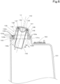
- the cap 140 is formed in a covered cylindrical shape for sealing the liquid supply opening 135.
- the internal screw portion 141 that is screwed to the external thread portion 139 formed on the outer peripheral surface of the cylindrical portion 137 is formed in an inner periphery of the cap 140 of the present embodiment.
- the cap 140 is configured to be able to be screwed to the cylindrical portion 137 of the tubular portion 132.
- An enclosing body 142 raised in a dome shape is formed on an inner peripheral portion (a back surface of a lid) of the cap 140.
- the enclosing body 142 is formed of an elastic material such as rubber, and is inserted into the cylindrical portion 137 to seal the inside of the cylindrical portion 137.
- the working machine 1 includes a tubular strainer 143 that is inserted into the tubular portion 132.
- the strainer 143 is inserted concentrically or substantially concentrically with the opening center line Lc of the liquid supply opening 135.
- the strainer 143 removes impurities contained in the fuel that is supplied to the fuel tank.
- the strainer 143 is formed in a tubular shape having a size that can be inserted into the tubular portion 132. That is, the outer diameter of the strainer 143 is slightly smaller than the opening diameter of the liquid supply opening 135, and the strainer 143 can be inserted into the tubular portion 132.
- strainer 143 One end portion of the strainer 143 is sandwiched between the cap 140 and the cylindrical portion 137, and in this state, the strainer 143 is configured to be concentric or substantially concentric with the opening center line Lc of the liquid supply opening 135. As illustrated in FIG. 7 , an opening 143a is formed in an upper portion of the strainer 143. A strainer gasket 155 for closely attaching the strainer 143 to the liquid supply opening 135 is provided at the opening 143a. A mesh 156 for filtering impurities in the fuel is provided on an outer peripheral portion of the strainer 143.
- the fuel tank 130 is configured as described above and is fixed to the machine body 2.
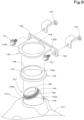
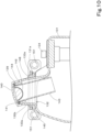
- the working machine 1 includes the fixing piece 133 and the elastic member 145 as means for fixing the fuel tank 130 to the machine body 2, as illustrated in FIGS. 9 and 10 .
- the fixing piece 133 is fitted on the elastic member 145 fitted on the tubular portion 132, substantially in parallel to the outer surface 131a of the tank body 131, and is fixed to the machine body 2.
- the fixing piece 133 is fixed to the machine body 2 to fix the tank 130 to the machine body 2.
- the fixing piece 133 has a first piece 133a and a second piece 133b connected to the first piece 133a.
- the first piece 133a is formed in a plate shape and is configured to be able to be superimposed on the outer surface (planar portion) 131a of the tank body 131.
- a through hole 149 into which the tubular portion 132 can be inserted is formed at the center of the first piece 133a.
- the through hole 149 is formed so that the tubular portion 132 (cylindrical portion 137) of the fuel tank 130 can be loosely fitted therein. That is, the opening diameter of the through hole 149 is set so that a gap is formed between the through hole 149 and the periphery of the inserted tubular portion 132 (cylindrical portion 137).
- the second piece 133b is connected to one end of the first piece 133a and extends in a direction orthogonal to the first piece 133a. Fixing holes 152 to fix fixing tools 151 are formed in both end portions of the second piece 133b.
- the second piece 133b is directly or indirectly fixed to the machine body 2 via the fixing tools (screw members) 151 inserted into the fixing holes 152 of the second piece 133b.
- the fixing piece 133 is fixed at a position at which the first piece 133a overlaps the upper surface (planar portion) 131a of the fuel tank 130 (tank body 131) disposed on the machine body 2 (turning base plate 5).
- the fixing piece 133 is fixed to an upper surface of the hydraulic fluid tank 150 fixed to the machine body 2, and is indirectly fixed to the machine body 2.
- the elastic member 145 is molded from an elastic material such as rubber, and reduces an impact acting on the fuel tank 130 by the fuel tank 130 being fixed to the machine body 2 (working machine 1).
- the elastic member 145 is fitted on the tubular portion 132 in a state of being substantially parallel to the outer surface 131a of the tank body 131 and non-perpendicular to the protruding direction of the tubular portion 132. That is, the elastic member 145 is formed in an annular shape and is configured to be able to be fitted on the tubular portion 132 of the fuel tank 130.
- An inner peripheral surface of the elastic member 145 has a shape that is substantially parallel to the outer surface 131a of the tank body 131 on the outer peripheral surface of the tubular portion 132 and that is in close contact with the annular contact area 132c non-perpendicular to the protruding direction of the tubular portion 132. That is, the inner peripheral surface of the elastic member 145 is formed in conformity with the outer peripheral surface of the tubular portion 132 and can be in close contact with the outer peripheral surface of the tubular portion 132.
- the elastic member 145 is fitted on the enlarged portion 136 of the tubular portion 132. Accordingly, the elastic member 145 has a through hole into which the enlarged portion 136 is fitted.
- the inner peripheral shape of the through hole is formed in conformity with the outer peripheral shape of the enlarged portion 136 of the tubular portion 132.
- an inner peripheral surface 145c defining the through hole can be in close contact with the outer surface of the enlarged portion 136 of the tubular portion 132 over the entire circumference.
- the elastic member 145 has a flange portion 147 that is sandwiched between the outer surface (planar portion 131a) of the tank body 131 and the fixing piece 133 (first piece 133a). Additionally, the elastic member 145 has an annular protruding portion 148 extending from the flange portion 147. The annular protruding portion 148 is sandwiched between the tubular portion 132 (enlarged portion 136) and an inner peripheral surface of the through hole 149 of the fixing piece 133 in the through hole 149 of the fixing piece 133.
- the flange portion 147 and the annular protruding portion 148 are integrally molded.
- the through hole of the elastic member 145 includes inner holes of the flange portion 147 and the annular protruding portion 148. That is, the inner holes of the flange portion 147 and the annular protruding portion 148 continuously form the through hole of the elastic member 145. Accordingly, the inner peripheral surface that is in contact with the contact area included in the outer peripheral surface of the tubular portion 132 is formed by an inner peripheral surface of the flange portion 147 and an inner peripheral surface of the annular protruding portion 148 being continuous.
- the thickness of the flange portion 147 is set so that the flange portion 147 is sandwiched in a compressed state between the first piece 133a of the fixing piece 133 fixed to the machine body 2 and the planar portion 131a of the fuel tank 130 supported by the machine body 2.
- the annular protruding portion 148 is disposed in a gap between the inner peripheral surface of the through hole 149 of the fixing piece 133 and the tubular portion 132 (enlarged portion 136).
- the thickness of the annular protruding portion 148 is set so that the annular protruding portion 148 is in a compressed state between the inner peripheral surface of the through hole 149 of the fixing piece 133 and the tubular portion 132 (enlarged portion 136).
- the elastic member 145 (annular protruding portion 148) fills the gap between the inner peripheral surface of the through hole 149 of the fixing piece 133 and the tubular portion 132 (enlarged portion 136), and absorbs a lateral impact acting on the fuel tank 130 while restricting lateral shaking of the fuel tank 130 (tubular portion 132).
- a portion of the annular protruding portion 148 protrudes from the fixing piece 133 toward the other end of the tubular portion 132 when the fixing piece 133 is fitted on the annular protruding portion 148. That is, the annular protruding portion 148 is also formed so as to protrude outward from the first piece 133a of the fixing piece 133. Specifically, an upper end of the annular protruding portion 148 protrudes further upward from the fixing piece 133. When the upper end of the annular protruding portion 148 protrudes upward from the fixing piece 133 in this manner, the upper end of the annular protruding portion 148 protruding upward from the fixing piece 133 is expanded by an elastic force of the elastic material.
- the expanded annular protruding portion 148 prevents or reduces coming off of the elastic member 145 downward from the through hole 149 of the fixing piece 133.
- the elastic member 145 of the present embodiment the elastic member 145 sandwiched between the outer surface 131a of the tank body 131 and the fixing piece 133 is less likely to come off.
- the elastic member 145 is brought close to the tubular portion 132 from the annular protruding portion 148 side in the direction orthogonal to the outer surface (planar portion) 131a of the tank body 131.
- the opening diameter of the annular protruding portion 148 of the elastic member 145 is equal to or slightly smaller than the outer diameter of the lower end (one end) of the tubular portion 132 (the outer diameter of the lower end of the enlarged portion 136).
- the other end of the tubular portion 132 having a smaller diameter than the diameter of the one end can be easily inserted into the opening of the annular protruding portion 148 having a larger opening diameter than the opening diameter of the other end.
- the liquid supply opening 135 is disposed so as to be accommodated within the range of the closed curve formed by the contact area 132c of the tubular portion 132 in the projection when viewed in the direction orthogonal to the planar portion 131a of the tank body 131, the elastic member 145 can be easily guided toward the one end of the tubular portion 132 by the elastic member 145 being moved straight in the direction orthogonal to the planar portion 131a.
- the inner peripheral surface 145c of the elastic member 145 is formed in conformity with the outer peripheral surface (the outer peripheral surface near the lower end) of the tubular portion 132, when the elastic member 145 is brought close to the outer peripheral surface 131a of the tank body 131 until the elastic member 145 comes into contact with the outer surface 131a, the inner peripheral surface 145c of the elastic member 145 comes into close contact with the outer peripheral surface of the tubular portion 132.
- the fixing piece 133 is brought close to the elastic member 145 in close contact with the outer peripheral surface of the tubular portion 132 (enlarged portion 136) in the direction orthogonal to the outer surface (planar portion) 131a of the tank body 131 (from above), and the tubular portion 132 and the annular protruding portion 148 are inserted (press-fitted) into the through hole 149 of the first piece 133a of the fixing piece 133.
- the elastic member 145 (flange portion 147) is sandwiched between the first piece 133a of the fixing piece 133 and the outer peripheral surface of the tubular portion 132.
- the fixing tools 151 are inserted into the fixing holes 152 of the second piece 133b of the fixing piece 133, and as illustrated in FIG. 14 , the fixing piece 133 is fixed to the machine body 2 (in the present embodiment, the upper surface of the hydraulic fluid tank 150 fixed to the machine body 2).
- the elastic member 145 and the fixing piece 133 can be assembled while the elastic member 145 and the fixing piece 133 are moved in the direction orthogonal to the outer surface 131a of the tank body 131.
- the example embodiments of the present invention provide a working machine 1 described in the following items.
- a working machine 1 comprising: a machine body 2; a tank 130 including a tank body 131 to store a liquid, and a tubular portion 132 protruding from an outer surface 131a of the tank body 131 in a protruding direction inclined with respect to the outer surface 13 la; a fixing piece 133 having a through hole 149 through which the tubular portion 132 is inserted, to fix the tank 130 to the machine body 2; and an elastic member 145 sandwiched between the fixing piece 133 and the tubular portion 132, wherein the tubular portion 132 has one end connected to the tank body 131 and another end defining a liquid supply opening 135, the elastic member 145 is fitted on the tubular portion 132 in a state of being substantially parallel to the outer surface 131a and non-perpendicular to the protruding direction of the tubular portion 132, and the fixing piece 133 is fitted on the elastic member 145 fitted on the tubular portion 132, substantially in parallel to the outer surface 131a, and is fixed to
- the elastic member 145 and the fixing piece 133 can be assembled to the tubular portion 132 protruding in the protruding direction inclined from the outer surface 131a of the tank body 131, substantially in parallel to the outer surface 131a of the tank body 131.
- the tank 130 including the tubular portion 132 protruding in the direction inclined from the tank body 131 can be easily fixed to the machine body 2.
- the elastic member 145 can be assembled only by being fitted on the tubular portion 132. Also, the tank 130 can be stably fixed by the close contact between the inner peripheral surface 145c of the elastic member 145 and the contact area 132c included in the outer peripheral surface of the tubular portion 132.
- the elastic member 145 can be easily assembled (fitted) to the tubular portion 132 simply by the elastic member 145 being caused to approach (brought close to) the outer surface 131a of the tank body 131 straight in the direction orthogonal to the outer surface 131a.
- (Item 4) The working machine 1 according to any one of Items 1 to 3, wherein the tubular portion 132 has an angle formed between an outer peripheral surface of the tubular portion 132 and the outer surface 131a in a section perpendicular to the outer surface 131a and passing through a center of the tubular portion 132 at the one end being 90° or more at any position in a circumferential direction of the tubular portion 132.
- the elastic member 145 can be caused to approach the outer surface 131a of the tank body 131 in the direction orthogonal to the outer surface 131a, and the elastic member 145 can be easily assembled to the tubular portion 132.
- a working machine 1 comprising: a machine body 2; a tank 130 including a tank body 131 to store a liquid, and a tubular portion 132 protruding from an outer surface 131a of the tank body 131 in a protruding direction inclined with respect to the outer surface 131a; a fixing piece 133 having a through hole 149 through which the tubular portion 132 is inserted, to fix the tank 130 to the machine body 2; and an elastic member 145 sandwiched between the fixing piece 133 and the tubular portion 132, wherein the tubular portion 132 has one end connected to the tank body 131 and another end defining a liquid supply opening 135, and the tubular portion 132 has an angle formed between an outer peripheral surface of the tubular portion 132 and the outer surface 131a in a section perpendicular to the outer surface 131a and passing through a center of the tubular portion 132 at the one end being 90° or more at any position in a circumferential direction of the tubular portion 132.
- the elastic member 145 can be caused to approach the outer surface 131a of the tank body 131 in the direction orthogonal to the outer surface 131a, and the elastic member 145 can be easily assembled to the tubular portion 132.
- the flange portion 147 is disposed between the outer surface 131a of the tank body 131 and the fixing piece 133. Hence a state is attained in which the elastic member 145 appropriately presses the tank body 131, and the tank 130 can be reliably fixed.
- the flange portion 147 is disposed between the outer surface 131a of the tank body 131 and the fixing piece 133, and also the annular protruding portion 148 is sandwiched between the tubular portion 132 and the inner peripheral surface of the through hole 149. Hence lateral shaking (rattling in the direction orthogonal to the hole center line of the through hole 149) of the tubular portion 132 is restricted.
- the portion of the annular protruding portion 148 protruding from the fixing piece 133 is expanded by the elastic force of the elastic member 145, and hence it is possible to prevent or reduce coming off of the elastic member 145 from the through hole 149 of the fixing piece 133.
- the elastic member 145 and the fixing piece 133 can be easily assembled by being caused to approach the upper surface (outer surface 131a) of the tank 130 from above the tank 130.
- the elastic member 145 can be easily assembled to the enlarged portion 136 whose sectional shape is enlarged from the portion near the other end toward the one end.
- the liquid supply opening 135 is easily accessible from the outside of the working machine 1.
- (Item 12) The working machine 1 according to any one of Items 1 to 11, wherein the tank 130 is a fuel tank to store fuel to be supplied to a prime mover 91 provided in the working machine 1.
- the example has been provided in which the tank of the present invention is applied to the fuel tank 130.
- the tank of the present invention may be applied to the hydraulic fluid tank 150 or may be applied to another tank provided in the working machine 1.
- the first portion 132a is formed over a half circumference of the tubular portion 132
- the second portion 132b is formed over the remaining half circumference of the tubular portion 132.
- the range in which the first portion 132a or the second portion 132b is provided is not limited to a half circumference.
- the first portion 132a or the second portion 132b may be provided over a range narrower than a half circumference in the circumferential direction.
- the first portion 132a or the second portion 132b may be provided over a range wider than a half circumference in the circumferential direction.
- the first portion 132a is formed in the substantially truncated semi-conical shape that is enlarged in the direction away from the point O toward the outside as the first portion 132a approaches the tank body 131, and the second portion 132b is formed in the semi-cylindrical shape around the axis extending in the direction perpendicular to the outer surface 131a.
- this does not imply any limitation.
- each of the first portion 132a and the second portion 132b may be formed in a substantially truncated semi-conical shape that is enlarged in the direction away from the point O toward the outside as the first portion 132a or the second portion 132b approaches the tank body 131, and the entire tubular portion 132 (enlarged portion 136) may be formed in a truncated conical shape.
- the tubular portion 132 includes the enlarged portion 136 and the cylindrical portion 137, and the enlarged portion 136 is enlarged toward the tank body 131, so that the tubular portion 132 is enlarged from the portion near the other end toward the one end.
- the tubular portion 132 may include only the enlarged portion 136. That is, only the enlarged portion 136 of the above-described embodiment may be the tubular portion 132. In this case, it is needless to say that the distal end opening of the enlarged portion 136 constitutes the liquid supply opening 135 facing obliquely upward. Also, it is needless to say that the description of the tubular portion 132 in this case can be understood by replacing the enlarged portion 136 in the description of the above-described embodiment with the tubular portion 132.
- the elastic member 145 (flange portion 147) is not limited to the one being sandwiched between the outer surface (planar portion) 131a of the tank body 131 and the fixing piece 133 (first piece 133a) over the entire circumference, and the elastic member 145 (flange portion 147) may be partly sandwiched between the outer surface (planar portion) 131a of the tank body 131 and the fixing piece 133 (first piece 133a).
- the elastic member 145 is not limited to the one having the annular protruding portion 148. That is, the elastic member 145 may have only a portion corresponding to the flange portion 147 in the above-described embodiment. However, in order to protect the tank 130 from lateral shaking or lateral impact, it is preferable to have the annular protruding portion 148 similarly to the above-described embodiment.
- a configuration may be provided in which the elastic member 145 fitted on the contact area 132c of the tubular portion 132 is sandwiched between the fixing piece 133 and the outer peripheral surface of the tubular portion 132 in a state of being separated from the outer surface 131a of the tank body 131.
- a configuration may be provided in which the elastic member 145 does not include the flange portion 147.
- the backhoe has been described as the working machine 1.
- the working machine 1 may be various construction machines other than the backhoe, or may be various agricultural machines such as a tractor and a combine.
Landscapes
- Engineering & Computer Science (AREA)
- Transportation (AREA)
- Sustainable Development (AREA)
- Sustainable Energy (AREA)
- Chemical & Material Sciences (AREA)
- Combustion & Propulsion (AREA)
- Life Sciences & Earth Sciences (AREA)
- Mechanical Engineering (AREA)
- Mining & Mineral Resources (AREA)
- Civil Engineering (AREA)
- General Engineering & Computer Science (AREA)
- Structural Engineering (AREA)
- Cooling, Air Intake And Gas Exhaust, And Fuel Tank Arrangements In Propulsion Units (AREA)
- Component Parts Of Construction Machinery (AREA)
Abstract
Description
- The present invention relates to a working machine including a tank that stores a liquid such as fuel.
- A working machine disclosed in
Japanese Unexamined Patent Application Publication No. 2021-185306 Japanese Unexamined Patent Application Publication No. 2021-185306 - However, in the technique of
Japanese Unexamined Patent Application Publication No. 2021-185306 - In view of the above problems, an object of the present invention is to easily fix a tank including a tubular portion protruding from a tank body in an inclined direction, to a machine body.
- A working machine according to an aspect of the present invention includes a machine body; a tank including a tank body to store a liquid, and a tubular portion protruding from an outer surface of the tank body in a protruding direction inclined with respect to the outer surface; a fixing piece having a through hole through which the tubular portion is inserted, to fix the tank to the machine body; and an elastic member sandwiched between the fixing piece and the tubular portion. The tubular portion has one end connected to the tank body and another end defining a liquid supply opening. The elastic member is fitted on the tubular portion in a state of being substantially parallel to the outer surface and non-perpendicular to the protruding direction of the tubular portion. The fixing piece is fitted on the elastic member fitted on the tubular portion, substantially in parallel to the outer surface, and is fixed to the machine body.
- According to the present invention, the tank including the tubular portion protruding from the tank body in the inclined direction can be easily fixed to the machine body.
- The above and other elements, features, steps, characteristics and advantages of the present invention will become more apparent from the following detailed description of the example embodiments with reference to the attached drawings.
- A more complete appreciation of example embodiments of the present invention and many of the attendant advantages thereof will be readily obtained as the same becomes better understood by reference to the following detailed description when considered in connection with the accompanying drawings described below.
-
FIG. 1 is an overall side view of a working machine according to an embodiment of the present invention as viewed from the right. -
FIG. 2 is an overall perspective view of the working machine according to the embodiment as viewed from the right. -
FIG. 3 is a plan view of a machine body of the working machine according to the embodiment. -
FIG. 4 is a perspective view illustrating an attachment structure of a tank to a turning base plate of the working machine according to the embodiment. -
FIG. 5 is a plan view of the tank of the working machine according to the embodiment as viewed from above. -
FIG. 6 is a partly sectional view taken along line VI-VI inFIG. 5 . -
FIG. 7 is a vertical sectional view of a strainer of the working machine according to the embodiment. -
FIG. 8 is a vertical sectional view of a cap of the working machine according to the embodiment. -
FIG. 9 is an exploded perspective view around a tubular portion of the working machine according to the embodiment. -
FIG. 10 is a partly sectional view taken along line VII-VII inFIG. 5 . -
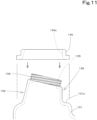
FIG. 11 is an explanatory view of a procedure for attaching an elastic member and a fixing piece to the tubular portion. -
FIG. 12 is an explanatory view of the procedure for attaching the elastic member and the fixing piece to the tubular portion. -
FIG. 13 is an explanatory view of the procedure for attaching the elastic member and the fixing piece to the tubular portion. -
FIG. 14 is an explanatory view of the procedure for attaching the elastic member and the fixing piece to the tubular portion. - Example embodiments will now be described with reference to the accompanying drawings, wherein like reference numerals designate corresponding or identical elements throughout the various drawings. The drawings are to be viewed in an orientation in which the reference numerals are viewed correctly.
- Hereinafter, an embodiment of the present invention will be described with reference to the drawings.
-
FIG. 1 is a side view illustrating an overall configuration of aworking machine 1 according to the present embodiment.FIG. 2 is a perspective view illustrating the overall configuration of theworking machine 1 according to the present embodiment. In the present embodiment, an arrow A1 direction inFIG. 1 is referred to as a forward side, an arrow A2 direction inFIG. 1 is referred to as a rearward side, and an arrow A3 direction inFIG. 1 is referred to as a front-rear direction. Also, a near side inFIG. 1 is referred to as a rightward side, and a far side inFIG. 1 is referred to as a leftward side. Further, a horizontal direction that is a direction orthogonal to the front-rear direction A3 is described as a width direction. - As illustrated in
FIGS. 1 and2 , theworking machine 1 of the present embodiment includes amachine body 2, atraveling device 3 that supports themachine body 2 so as to be capable of traveling, a prime mover 91 (seeFIG. 3 ), and aworking device 4. Theprime mover 91 drives a hydraulic pump 95 (described later), and thetraveling device 3 and theworking device 4 are driven with hydraulic pressure supplied from thehydraulic pump 95. - In the present embodiment, the
working machine 1 includes, in addition to theprime mover 91, aweight 25 for balancing the weight with theworking device 4, a cabin that houses an operator'sseat 6, and the like, and themachine body 2 supports mounted objects such as theprime mover 91, theweight 25, and the cabin. - Specifically, as illustrated in
FIG. 2 , themachine body 2 includes a frame to which thetraveling device 3 is coupled, a turning bearing fixed to the frame, and aturning base plate 5 rotatably (turnably) attached to the frame via the turning bearing, and the operator's seat 6 (cabin), theweight 25, and the like are disposed on theturning base plate 5. In the present embodiment, theworking machine 1 includes acover 14 that covers theprime mover 91, theweight 25, and the like. That is, the mounted objects such as theweight 25 are covered with the cover (hereinafter, referred to as an exterior cover) 14. - In the present embodiment, the
traveling device 3 is a crawler travel device (endless belt traveling device). Theprime mover 91 is an internal combustion engine (engine). Accordingly, as illustrated inFIG. 3 , theworking machine 1 includes a tank (hereinafter, referred to as a fuel tank) 130 that stores fuel to be supplied to theprime mover 91. - The
prime mover 91 is mounted in a center portion in the width direction of a rear portion of themachine body 2. Theprime mover 91 is disposed below the operator'sseat 6. Aradiator 92, anoil cooler 93, ahydraulic pump 95, and acooling fan 100 are disposed both leftward and rightward of theprime mover 91. - A right portion of the
exterior cover 14 extends to protrude forward to the vicinity of a right front end of themachine body 2. Thefuel tank 130 and ahydraulic fluid tank 150 are disposed inside the right portion of theexterior cover 14. Adoor 154 with a locking function that enables access to thefuel tank 130 during refueling or the like is provided in an outer side surface of the right portion of theexterior cover 14. - The
fuel tank 130 stores fuel such as light oil or gasoline. As illustrated inFIG. 4 , thefuel tank 130 is disposed on theturning base plate 5 that is a portion of themachine body 2. Although details will be described later, in the present embodiment, thefuel tank 130 is fixed in a state of being supported by theturning base plate 5. - As illustrated in
FIG. 5 , thefuel tank 130 includes atank body 131 that stores a liquid, and atubular portion 132 protruding in a protruding direction inclined with respect to anouter surface 131a of thetank body 131. On the premise that thefuel tank 130 includes thetank body 131 and thetubular portion 132, theworking machine 1 includes, as means for fixing thefuel tank 130, afixing piece 133 that has a throughhole 149 through which thetubular portion 132 is inserted and fixes thefuel tank 130 to themachine body 2, and anelastic member 145 sandwiched between thefixing piece 133 and thetubular portion 132. - First, the
fuel tank 130 will be described in detail. As illustrated inFIG. 4 , thefuel tank 130 is disposed with theouter surface 131a of thetank body 131 facing upward. Thetank body 131 is formed to have one direction in a longitudinal direction. In the present embodiment, thetank body 131 is disposed to have the one direction in a vertical direction. That is, thetank body 131 is a vertically long container that stores a liquid, and is formed of synthetic resin or the like. Thetank body 131 is hollow and stores liquid fuel. Thetank body 131 is disposed in an upright state on the turningbase plate 5. As illustrated inFIG. 6 , aplanar portion 131a is included in one surface in one direction of outer surfaces of thetank body 131. That is, theplanar portion 131a is included in an upper surface that is the one surface in the up-down direction of the outer surfaces of thetank body 131. - The
tubular portion 132 has one end connected to thetank body 131 and another end defining aliquid supply opening 135. Thus, thetubular portion 132 protrudes from theouter surface 131a of thetank body 131. In the present embodiment, thetubular portion 132 protrudes in the protruding direction inclined with respect to theplanar portion 131a of the upper surface that is the outer surface of thetank body 131. In this case, in the present embodiment, the protruding direction is an outward side of themachine body 2 with respect to a vertically upward side. - That is, the upper surface of the
tank body 131 is "anouter surface 131a from which thetubular portion 132 protrudes (anouter surface 131a to which a proximal end of thetubular portion 132 is connected)". In the present embodiment, the upper surface (the outer surface facing upward) of thetank body 131 has a high portion and a low portion, and the high portion is theplanar portion 131a. - As illustrated in
FIGS. 4 to 6 , thetubular portion 132 protrudes from theplanar portion 131a at the high portion of the upper surface of thetank body 131 having the high portion and the low portion, andliquid level sensors planar portion 131a. Thetubular portion 132 is disposed at a position shifted from a center portion of the upper surface of thetank body 131. In the present embodiment, the tubular portion 132 (planar portion 131a) is positioned at a substantially center portion near one side surface of a peripheral wall of thetank body 131. In the present embodiment, the one side surface of the peripheral wall of thetank body 131 is located in a backward direction of the travelingdevice 3, and accordingly, the tubular portion 132 (planar portion 131a) is disposed at a center portion in the left-right direction of a rear portion of the upper surface. Accordingly, theliquid level sensor 153 is disposed at a front portion of the upper surface of the tank body 131 (forward of the tubular portion 132), and theliquid level sensor 134 is disposed at a lateral portion of the upper surface of the tank body 131 (beside the tubular portion 132: leftward in the present embodiment). In the present embodiment, theliquid level sensor 153 detects the liquid level of the liquid stored in thetank body 131 using a float, and displays the amount of liquid in the tank using a needle that moves in association with the float. Theliquid level sensor 134 detects the liquid level in the tank and sends a signal corresponding to the detection result to a controller (not illustrated). Thus, the amount of liquid corresponding to the detection result of theliquid level sensor 134 is displayed on a meter panel (not illustrated). - The
tubular portion 132 will be described in more detail. As illustrated inFIGS. 5 and6 , thetubular portion 132 has the one end connected to thetank body 131, a middle portion extending obliquely upward from the one end, and the other end defining the liquid supply opening (oil supply opening) 135 opened obliquely upward. An opening center line Lc, which is a straight line passing through the center of theliquid supply opening 135 and orthogonal to an opening end surface (another end surface, an imaginary plane including an end portion near the other end of the tubular portion 132) of theliquid supply opening 135, is inclined toward a machine-body outward side (obliquely forward and rightward in the present embodiment) with respect to a direction orthogonal to theouter surface 131a of the tank body 131 (the vertical direction in the present embodiment). That is, the opening center line Lc extends obliquely upward in an inclination direction (an extending direction of the middle portion) of thetubular portion 132. - In the present embodiment, the
elastic member 145 is fitted on an outer peripheral surface of thetubular portion 132. Theelastic member 145 is in contact with (is in close contact with) a predetermined area (contact area 132c) of the outer peripheral surface of thetubular portion 132. As illustrated inFIG. 6 , thecontact area 132c is an area between a lower limit position (a position of a lower end of theelastic member 145 that is fitted) DB near the one end of thetubular portion 132 and an upper limit position (a position of an upper end of theelastic member 145 that is fitted) UB near the other end of thetubular portion 132. - The
contact area 132c of thetubular portion 132 has the lower limit position DB at the one end of thetubular portion 132 and the upper limit position UB at a position separated from the lower limit position DB by a width of theelastic member 145. Thetubular portion 132 is disposed such that a portion of thetubular portion 132 closer to the other end than thecontact area 132c is accommodated within a range of a closed curve formed by thecontact area 132c in a projection when viewed in the direction orthogonal to theouter surface 131a. In this case, the "closed curve formed by thecontact area 132c" means a contour of thecontact area 132c when viewed in the direction orthogonal to the outer surface (planar portion) 131a. In the present embodiment, theliquid supply opening 135 is disposed so as to be accommodated within a range of an annular contour (closed curve) of an outer periphery of thetubular portion 132 at the upper limit position UB of thecontact area 132c in a projection when viewed in the direction orthogonal to the outer surface (planar portion) 131a. - The
tubular portion 132 has an angle formed by the outer peripheral surface of thetubular portion 132 and theouter surface 131a in a section perpendicular to theouter surface 131a and passing through the center of thetubular portion 132 at the one end being 90° or more at any position in the circumferential direction of thetubular portion 132. The outer peripheral surface of thetubular portion 132 has an inclination at an angle of 90° or more with respect to theouter surface 131a at any position in the circumferential direction. - As illustrated in
FIG. 6 , thetubular portion 132 is enlarged from a portion near the other end (upper end) toward the one end (lower end). That is, thetubular portion 132 includes anenlarged portion 136 whose sectional shape is enlarged from the portion near the other end toward the one end. In the present embodiment, thetubular portion 132 includes theenlarged portion 136 protruding from thetank body 131 and enlarged toward thetank body 131, and acylindrical portion 137 being continuous with a distal end of theenlarged portion 136 and defining theliquid supply opening 135. - Before describing the angle formed between the outer peripheral surface of the tubular portion 132 (enlarged portion 136) and the
outer surface 131a, points O and P1 to P4 used for the description will be described with reference toFIGS. 5 and6 . As illustrated inFIG. 6 , the point O is an intersection point of an imaginary plane passing through the lower limit position DB of thecontact area 132c and the opening center line Lc. The points P1 to P4 are positions (points) on the imaginary plane passing through the lower limit position DB of thecontact area 132c, and are located around the point O. That is, the points P1 to P4 are located on the line of a contour H of the lower limit position DB indicated by a broken line inFIG. 5 . The point P1 is located forward and outward (in the protruding direction of the tubular portion 132) when viewed from the point O, the point P3 is located rearward and inward (opposite to the protruding direction of the tubular portion 132) when viewed from the point O, and the points P2 and P4 are located in a direction orthogonal to an imaginary straight line connecting the points P1 and P3 when viewed from the point O. A projected line L0 indicated by a two-dot chain line inFIG. 5 is a straight line indicating the opening center line Lc projected from above, and extends through the point O, the point P1, and the point P3. The projected line L0 is inclined at an inclination angle θ1 with respect to a rightward direction X and at an inclination angle θ2 with respect to a forward direction Y. In the present embodiment, the inclination angle θ1 is 45°, and the inclination angle θ2 is 45°. - The enlarged portion 136 (tubular portion 132) has a
first portion 132a and asecond portion 132b in the circumferential direction, thesecond portion 132b connecting both ends in the circumferential direction of thefirst portion 132a. - The
first portion 132a is formed in the circumferential direction at a rear inner portion of a sectional shape of thetubular portion 132. As illustrated inFIG. 5 , thefirst portion 132a of the present embodiment is formed in a half circumference from the point P4 to the point P2 through the point P3 of thetubular portion 132. Thefirst portion 132a is formed in a shape (substantially truncated semi-conical shape) that is enlarged in a direction away from the center (a position indicated by the point O) of the sectional shape of thetubular portion 132 toward the outside as thefirst portion 132a approaches thetank body 131. - The
second portion 132b is formed in the circumferential direction at a front outer portion of the sectional shape of thetubular portion 132. Thesecond portion 132b of the present embodiment is formed in a half circumference from the point P2 to the point P4 through the point P1 of thetubular portion 132. Thesecond portion 132b is formed to be a cylindrical surface around an axis extending from the point O of theouter surface 131a of thetank body 131 in a direction perpendicular to theouter surface 131a. - As illustrated in
FIG. 6 , an outer peripheral surface of thefirst portion 132a has an angle exceeding 90° with respect to theplanar portion 131a of thetank body 131 at any position in the circumferential direction, and an outer peripheral surface of thesecond portion 132b has an angle of 90° with respect to theplanar portion 131a of thetank body 131 at any position in the circumferential direction. That is, in thetubular portion 132 of the present embodiment, thefirst portion 132a is formed in a substantially truncated semi-conical shape, and thesecond portion 132b is formed in a semi-cylindrical shape. Thus, the outer peripheral surface of thefirst portion 132a is a semi-conical surface, and the outer peripheral surface of thesecond portion 132b is a semi-conical surface. - The
cylindrical portion 137 is a portion in which the outer diameter of thetubular portion 132 is the same from another end (upper end) toward one end (lower end). Thecylindrical portion 137 is provided further upward of the upper end (distal end) of theenlarged portion 136, that is, continuously in an upper portion of thetubular portion 132. An opening is formed at the upper end of thecylindrical portion 137, and the opening defines theliquid supply opening 135 for supplying the liquid into thetank body 131. Thus, the inner diameter of thecylindrical portion 137 is equal to the opening diameter of theliquid supply opening 135. - An
external thread portion 139 is formed on an outer peripheral surface of thecylindrical portion 137. Theexternal thread portion 139 is screwed to aninternal screw portion 141 of acap 140. That is, thecylindrical portion 137 is configured to be able to be screwed to thecap 140. - The outer diameter of the
cylindrical portion 137 is smaller than the outer diameter of the distal end (a distal end portion with a reduced diameter) of theenlarged portion 136. The outer diameter of thecylindrical portion 137 is smaller than the outer diameter of the distal end of theenlarged portion 136. - More specifically, since the
second portion 132b of theenlarged portion 136 is at 90° with respect to theplanar portion 131a of thetank body 131, when thecylindrical portion 137 is connected to theenlarged portion 136 so that theliquid supply opening 135 faces obliquely upward, theliquid supply opening 135 is located outside thesecond portion 132b. - In the present embodiment, the outer diameter of the
cylindrical portion 137 is set to be smaller than the outer diameter of the distal end of theenlarged portion 136 such that theliquid supply opening 135 is accommodated within the range of the closed curve formed by thecontact area 132c of thetubular portion 132 in the projection when viewed in the direction orthogonal to the outer surface (planar portion) 131a. Note that thecap 140 does not have to be accommodated within the range of the closed curve in the projection when viewed in the direction orthogonal to the outer surface (planar portion) 131a. - Accordingly, a
step portion 144 that increases in diameter from thecylindrical portion 137 to theenlarged portion 136 is formed between thecylindrical portion 137 and theenlarged portion 136. - As illustrated in
FIG. 8 , thecap 140 is formed in a covered cylindrical shape for sealing theliquid supply opening 135. Theinternal screw portion 141 that is screwed to theexternal thread portion 139 formed on the outer peripheral surface of thecylindrical portion 137 is formed in an inner periphery of thecap 140 of the present embodiment. Thus, thecap 140 is configured to be able to be screwed to thecylindrical portion 137 of thetubular portion 132. - An enclosing
body 142 raised in a dome shape is formed on an inner peripheral portion (a back surface of a lid) of thecap 140. The enclosingbody 142 is formed of an elastic material such as rubber, and is inserted into thecylindrical portion 137 to seal the inside of thecylindrical portion 137. - As illustrated in
FIG. 6 , the workingmachine 1 includes atubular strainer 143 that is inserted into thetubular portion 132. Thestrainer 143 is inserted concentrically or substantially concentrically with the opening center line Lc of theliquid supply opening 135. Thestrainer 143 removes impurities contained in the fuel that is supplied to the fuel tank. As illustrated inFIGS. 6 and7 , thestrainer 143 is formed in a tubular shape having a size that can be inserted into thetubular portion 132. That is, the outer diameter of thestrainer 143 is slightly smaller than the opening diameter of theliquid supply opening 135, and thestrainer 143 can be inserted into thetubular portion 132. One end portion of thestrainer 143 is sandwiched between thecap 140 and thecylindrical portion 137, and in this state, thestrainer 143 is configured to be concentric or substantially concentric with the opening center line Lc of theliquid supply opening 135. As illustrated inFIG. 7 , anopening 143a is formed in an upper portion of thestrainer 143. Astrainer gasket 155 for closely attaching thestrainer 143 to theliquid supply opening 135 is provided at theopening 143a. Amesh 156 for filtering impurities in the fuel is provided on an outer peripheral portion of thestrainer 143. - The
fuel tank 130 is configured as described above and is fixed to themachine body 2. As described above, the workingmachine 1 includes the fixingpiece 133 and theelastic member 145 as means for fixing thefuel tank 130 to themachine body 2, as illustrated inFIGS. 9 and10 . - The fixing
piece 133 is fitted on theelastic member 145 fitted on thetubular portion 132, substantially in parallel to theouter surface 131a of thetank body 131, and is fixed to themachine body 2. The fixingpiece 133 is fixed to themachine body 2 to fix thetank 130 to themachine body 2. Describing more specifically, the fixingpiece 133 has afirst piece 133a and asecond piece 133b connected to thefirst piece 133a. - The
first piece 133a is formed in a plate shape and is configured to be able to be superimposed on the outer surface (planar portion) 131a of thetank body 131. - A through
hole 149 into which thetubular portion 132 can be inserted is formed at the center of thefirst piece 133a. In the present embodiment, the throughhole 149 is formed so that the tubular portion 132 (cylindrical portion 137) of thefuel tank 130 can be loosely fitted therein. That is, the opening diameter of the throughhole 149 is set so that a gap is formed between the throughhole 149 and the periphery of the inserted tubular portion 132 (cylindrical portion 137). - The
second piece 133b is connected to one end of thefirst piece 133a and extends in a direction orthogonal to thefirst piece 133a. Fixingholes 152 to fix fixingtools 151 are formed in both end portions of thesecond piece 133b. Thesecond piece 133b is directly or indirectly fixed to themachine body 2 via the fixing tools (screw members) 151 inserted into the fixingholes 152 of thesecond piece 133b. In the present embodiment, the fixingpiece 133 is fixed at a position at which thefirst piece 133a overlaps the upper surface (planar portion) 131a of the fuel tank 130 (tank body 131) disposed on the machine body 2 (turning base plate 5). In the present embodiment, the fixingpiece 133 is fixed to an upper surface of thehydraulic fluid tank 150 fixed to themachine body 2, and is indirectly fixed to themachine body 2. - The
elastic member 145 is molded from an elastic material such as rubber, and reduces an impact acting on thefuel tank 130 by thefuel tank 130 being fixed to the machine body 2 (working machine 1). - The
elastic member 145 is fitted on thetubular portion 132 in a state of being substantially parallel to theouter surface 131a of thetank body 131 and non-perpendicular to the protruding direction of thetubular portion 132. That is, theelastic member 145 is formed in an annular shape and is configured to be able to be fitted on thetubular portion 132 of thefuel tank 130. - An inner peripheral surface of the
elastic member 145 has a shape that is substantially parallel to theouter surface 131a of thetank body 131 on the outer peripheral surface of thetubular portion 132 and that is in close contact with theannular contact area 132c non-perpendicular to the protruding direction of thetubular portion 132. That is, the inner peripheral surface of theelastic member 145 is formed in conformity with the outer peripheral surface of thetubular portion 132 and can be in close contact with the outer peripheral surface of thetubular portion 132. In the present embodiment, theelastic member 145 is fitted on theenlarged portion 136 of thetubular portion 132. Accordingly, theelastic member 145 has a through hole into which theenlarged portion 136 is fitted. The inner peripheral shape of the through hole is formed in conformity with the outer peripheral shape of theenlarged portion 136 of thetubular portion 132. Thus, in theelastic member 145, an innerperipheral surface 145c defining the through hole can be in close contact with the outer surface of theenlarged portion 136 of thetubular portion 132 over the entire circumference. - The
elastic member 145 has aflange portion 147 that is sandwiched between the outer surface (planar portion 131a) of thetank body 131 and the fixing piece 133 (first piece 133a). Additionally, theelastic member 145 has an annular protrudingportion 148 extending from theflange portion 147. The annular protrudingportion 148 is sandwiched between the tubular portion 132 (enlarged portion 136) and an inner peripheral surface of the throughhole 149 of the fixingpiece 133 in the throughhole 149 of the fixingpiece 133. - The
flange portion 147 and the annular protrudingportion 148 are integrally molded. The through hole of theelastic member 145 includes inner holes of theflange portion 147 and the annular protrudingportion 148. That is, the inner holes of theflange portion 147 and the annular protrudingportion 148 continuously form the through hole of theelastic member 145. Accordingly, the inner peripheral surface that is in contact with the contact area included in the outer peripheral surface of thetubular portion 132 is formed by an inner peripheral surface of theflange portion 147 and an inner peripheral surface of the annular protrudingportion 148 being continuous. The thickness of theflange portion 147 is set so that theflange portion 147 is sandwiched in a compressed state between thefirst piece 133a of the fixingpiece 133 fixed to themachine body 2 and theplanar portion 131a of thefuel tank 130 supported by themachine body 2. In contrast, the annular protrudingportion 148 is disposed in a gap between the inner peripheral surface of the throughhole 149 of the fixingpiece 133 and the tubular portion 132 (enlarged portion 136). The thickness of the annular protrudingportion 148 is set so that the annular protrudingportion 148 is in a compressed state between the inner peripheral surface of the throughhole 149 of the fixingpiece 133 and the tubular portion 132 (enlarged portion 136). Thus, the elastic member 145 (annular protruding portion 148) fills the gap between the inner peripheral surface of the throughhole 149 of the fixingpiece 133 and the tubular portion 132 (enlarged portion 136), and absorbs a lateral impact acting on thefuel tank 130 while restricting lateral shaking of the fuel tank 130 (tubular portion 132). - A portion of the annular protruding
portion 148 protrudes from the fixingpiece 133 toward the other end of thetubular portion 132 when the fixingpiece 133 is fitted on the annular protrudingportion 148. That is, the annular protrudingportion 148 is also formed so as to protrude outward from thefirst piece 133a of the fixingpiece 133. Specifically, an upper end of the annular protrudingportion 148 protrudes further upward from the fixingpiece 133. When the upper end of the annular protrudingportion 148 protrudes upward from the fixingpiece 133 in this manner, the upper end of the annular protrudingportion 148 protruding upward from the fixingpiece 133 is expanded by an elastic force of the elastic material. The expanded annular protrudingportion 148 prevents or reduces coming off of theelastic member 145 downward from the throughhole 149 of the fixingpiece 133. Thus, with theelastic member 145 of the present embodiment, theelastic member 145 sandwiched between theouter surface 131a of thetank body 131 and the fixingpiece 133 is less likely to come off. - Next, a procedure for assembling the
elastic member 145 and the fixingpiece 133 to thetubular portion 132 will be described with reference toFIGS. 11 to 14 . - As illustrated in
FIG. 11 , theelastic member 145 is brought close to thetubular portion 132 from the annular protrudingportion 148 side in the direction orthogonal to the outer surface (planar portion) 131a of thetank body 131. The opening diameter of the annular protrudingportion 148 of theelastic member 145 is equal to or slightly smaller than the outer diameter of the lower end (one end) of the tubular portion 132 (the outer diameter of the lower end of the enlarged portion 136). Thus, the other end of thetubular portion 132 having a smaller diameter than the diameter of the one end can be easily inserted into the opening of the annular protrudingportion 148 having a larger opening diameter than the opening diameter of the other end. Also, since theliquid supply opening 135 is disposed so as to be accommodated within the range of the closed curve formed by thecontact area 132c of thetubular portion 132 in the projection when viewed in the direction orthogonal to theplanar portion 131a of thetank body 131, theelastic member 145 can be easily guided toward the one end of thetubular portion 132 by theelastic member 145 being moved straight in the direction orthogonal to theplanar portion 131a. Since the innerperipheral surface 145c of theelastic member 145 is formed in conformity with the outer peripheral surface (the outer peripheral surface near the lower end) of thetubular portion 132, when theelastic member 145 is brought close to the outerperipheral surface 131a of thetank body 131 until theelastic member 145 comes into contact with theouter surface 131a, the innerperipheral surface 145c of theelastic member 145 comes into close contact with the outer peripheral surface of thetubular portion 132. - Then, as illustrated in
FIG. 12 , the fixingpiece 133 is brought close to theelastic member 145 in close contact with the outer peripheral surface of the tubular portion 132 (enlarged portion 136) in the direction orthogonal to the outer surface (planar portion) 131a of the tank body 131 (from above), and thetubular portion 132 and the annular protrudingportion 148 are inserted (press-fitted) into the throughhole 149 of thefirst piece 133a of the fixingpiece 133. Along with this, the elastic member 145 (flange portion 147) is sandwiched between thefirst piece 133a of the fixingpiece 133 and the outer peripheral surface of thetubular portion 132. - As illustrated in
FIG. 13 , when theelastic member 145 is sandwiched between thefirst piece 133a of the fixingpiece 133 and the outer peripheral surface of thetubular portion 132, the fixingtools 151 are inserted into the fixingholes 152 of thesecond piece 133b of the fixingpiece 133, and as illustrated inFIG. 14 , the fixingpiece 133 is fixed to the machine body 2 (in the present embodiment, the upper surface of thehydraulic fluid tank 150 fixed to the machine body 2). - Accordingly, the
elastic member 145 and the fixingpiece 133 can be assembled while theelastic member 145 and the fixingpiece 133 are moved in the direction orthogonal to theouter surface 131a of thetank body 131. - The example embodiments of the present invention provide a working
machine 1 described in the following items. - (Item 1) A working
machine 1 comprising: amachine body 2; atank 130 including atank body 131 to store a liquid, and atubular portion 132 protruding from anouter surface 131a of thetank body 131 in a protruding direction inclined with respect to the outer surface 13 la; afixing piece 133 having a throughhole 149 through which thetubular portion 132 is inserted, to fix thetank 130 to themachine body 2; and anelastic member 145 sandwiched between the fixingpiece 133 and thetubular portion 132, wherein thetubular portion 132 has one end connected to thetank body 131 and another end defining aliquid supply opening 135, theelastic member 145 is fitted on thetubular portion 132 in a state of being substantially parallel to theouter surface 131a and non-perpendicular to the protruding direction of thetubular portion 132, and the fixingpiece 133 is fitted on theelastic member 145 fitted on thetubular portion 132, substantially in parallel to theouter surface 131a, and is fixed to themachine body 2. - With the working
machine 1 according toItem 1, theelastic member 145 and the fixingpiece 133 can be assembled to thetubular portion 132 protruding in the protruding direction inclined from theouter surface 131a of thetank body 131, substantially in parallel to theouter surface 131a of thetank body 131. Hence thetank 130 including thetubular portion 132 protruding in the direction inclined from thetank body 131 can be easily fixed to themachine body 2. - (Item 2) The working
machine 1 according toItem 1, wherein an innerperipheral surface 145c of theelastic member 145 has a shape in close contact with anannular contact area 131a of an outer peripheral surface of thetubular portion 132, thecontact area 132c being substantially parallel to theouter surface 131a and non-perpendicular to the protruding direction of thetubular portion 132. - With the working
machine 1 according toItem 2, theelastic member 145 can be assembled only by being fitted on thetubular portion 132. Also, thetank 130 can be stably fixed by the close contact between the innerperipheral surface 145c of theelastic member 145 and thecontact area 132c included in the outer peripheral surface of thetubular portion 132. - (Item 3) The working
machine 1 according toItem 2, wherein thetubular portion 132 is disposed such that a portion of thetubular portion 132 closer to the other end than thecontact area 132c is accommodated within a range of a closed curve formed by thecontact area 132c in a projection when viewed in a direction orthogonal to theouter surface 131a. - With the working
machine 1 according toItem 3, theelastic member 145 can be easily assembled (fitted) to thetubular portion 132 simply by theelastic member 145 being caused to approach (brought close to) theouter surface 131a of thetank body 131 straight in the direction orthogonal to theouter surface 131a. - (Item 4) The working
machine 1 according to any one ofItems 1 to 3, wherein thetubular portion 132 has an angle formed between an outer peripheral surface of thetubular portion 132 and theouter surface 131a in a section perpendicular to theouter surface 131a and passing through a center of thetubular portion 132 at the one end being 90° or more at any position in a circumferential direction of thetubular portion 132. - With the working
machine 1 according toItem 4, theelastic member 145 can be caused to approach theouter surface 131a of thetank body 131 in the direction orthogonal to theouter surface 131a, and theelastic member 145 can be easily assembled to thetubular portion 132. - (Item 5) A working
machine 1 comprising: amachine body 2; atank 130 including atank body 131 to store a liquid, and atubular portion 132 protruding from anouter surface 131a of thetank body 131 in a protruding direction inclined with respect to theouter surface 131a; afixing piece 133 having a throughhole 149 through which thetubular portion 132 is inserted, to fix thetank 130 to themachine body 2; and anelastic member 145 sandwiched between the fixingpiece 133 and thetubular portion 132, wherein thetubular portion 132 has one end connected to thetank body 131 and another end defining aliquid supply opening 135, and thetubular portion 132 has an angle formed between an outer peripheral surface of thetubular portion 132 and theouter surface 131a in a section perpendicular to theouter surface 131a and passing through a center of thetubular portion 132 at the one end being 90° or more at any position in a circumferential direction of thetubular portion 132. - With the working
machine 1 according toItem 5, theelastic member 145 can be caused to approach theouter surface 131a of thetank body 131 in the direction orthogonal to theouter surface 131a, and theelastic member 145 can be easily assembled to thetubular portion 132. - (Item 6) The working
machine 1 according to any one ofItems 1 to 4, wherein theelastic member 145 has aflange portion 147 sandwiched between theouter surface 131a and the fixingpiece 133. - With the working
machine 1 according toItem 6, theflange portion 147 is disposed between theouter surface 131a of thetank body 131 and the fixingpiece 133. Hence a state is attained in which theelastic member 145 appropriately presses thetank body 131, and thetank 130 can be reliably fixed. - (Item 7) The working
machine 1 according toItem 6, wherein theelastic member 145 has an annular protrudingportion 148 extending from theflange portion 147, the annular protrudingportion 148 being sandwiched between thetubular portion 132 and an inner peripheral surface of the throughhole 149 in the throughhole 149. - With the working
machine 1 according to Item 7, as described above, theflange portion 147 is disposed between theouter surface 131a of thetank body 131 and the fixingpiece 133, and also the annular protrudingportion 148 is sandwiched between thetubular portion 132 and the inner peripheral surface of the throughhole 149. Hence lateral shaking (rattling in the direction orthogonal to the hole center line of the through hole 149) of thetubular portion 132 is restricted. - (Item 8) The working
machine 1 according to Item 7, wherein a portion of the annular protrudingportion 148 protrudes from the fixingpiece 133 toward the other end when the fixingpiece 133 is fitted on the annular protrudingportion 148. - With the working
machine 1 according to Item 8, the portion of the annular protrudingportion 148 protruding from the fixingpiece 133 is expanded by the elastic force of theelastic member 145, and hence it is possible to prevent or reduce coming off of theelastic member 145 from the throughhole 149 of the fixingpiece 133. - (Item 9) The working
machine 1 according toItem 1, wherein thetank 130 is disposed with theouter surface 131a facing upward. - With the working
machine 1 according to Item 9, theelastic member 145 and the fixingpiece 133 can be easily assembled by being caused to approach the upper surface (outer surface 131a) of thetank 130 from above thetank 130. - (Item 10) The working
machine 1 according to any one ofItems 1 to 9, wherein thetubular portion 132 includes anenlarged portion 136 whose sectional shape is enlarged from a portion near the other end toward the one end, and theelastic member 145 is fitted on theenlarged portion 136. - With the working
machine 1 according to Item 10, theelastic member 145 can be easily assembled to theenlarged portion 136 whose sectional shape is enlarged from the portion near the other end toward the one end. - (Item 11) The working
machine 1 according to any one ofItems 1 to 10, wherein the protruding direction is inclined outward of themachine body 2 with respect to a vertically upward side. - With the working
machine 1 according to Item 11, theliquid supply opening 135 is easily accessible from the outside of the workingmachine 1. - (Item 12) The working
machine 1 according to any one ofItems 1 to 11, wherein thetank 130 is a fuel tank to store fuel to be supplied to aprime mover 91 provided in the workingmachine 1. - With the working
machine 1 according to Item 12, it is possible to smoothly perform daily refueling work. - While example embodiments of the present invention have been described above, it is to be understood that variations and modifications will be apparent to those skilled in the art without departing from the scope and spirit of the present invention. The scope of the present invention, therefore, is to be determined solely by the following claims.
- In the above-described embodiment, the example has been provided in which the tank of the present invention is applied to the
fuel tank 130. However, the tank of the present invention may be applied to thehydraulic fluid tank 150 or may be applied to another tank provided in the workingmachine 1. - In the above-described embodiment, the
first portion 132a is formed over a half circumference of thetubular portion 132, and thesecond portion 132b is formed over the remaining half circumference of thetubular portion 132. However, this does not imply any limitation. That is, the range in which thefirst portion 132a or thesecond portion 132b is provided is not limited to a half circumference. For example, thefirst portion 132a or thesecond portion 132b may be provided over a range narrower than a half circumference in the circumferential direction. Alternatively, thefirst portion 132a or thesecond portion 132b may be provided over a range wider than a half circumference in the circumferential direction. - In the above-described embodiment, the
first portion 132a is formed in the substantially truncated semi-conical shape that is enlarged in the direction away from the point O toward the outside as thefirst portion 132a approaches thetank body 131, and thesecond portion 132b is formed in the semi-cylindrical shape around the axis extending in the direction perpendicular to theouter surface 131a. However, this does not imply any limitation. For example, each of thefirst portion 132a and thesecond portion 132b may be formed in a substantially truncated semi-conical shape that is enlarged in the direction away from the point O toward the outside as thefirst portion 132a or thesecond portion 132b approaches thetank body 131, and the entire tubular portion 132 (enlarged portion 136) may be formed in a truncated conical shape. - In the above-described embodiment, the
tubular portion 132 includes theenlarged portion 136 and thecylindrical portion 137, and theenlarged portion 136 is enlarged toward thetank body 131, so that thetubular portion 132 is enlarged from the portion near the other end toward the one end. However, this does not imply any limitation. For example, when thecap 140 for sealing theliquid supply opening 135 is of a fit-in type, thetubular portion 132 may include only theenlarged portion 136. That is, only theenlarged portion 136 of the above-described embodiment may be thetubular portion 132. In this case, it is needless to say that the distal end opening of theenlarged portion 136 constitutes theliquid supply opening 135 facing obliquely upward. Also, it is needless to say that the description of thetubular portion 132 in this case can be understood by replacing theenlarged portion 136 in the description of the above-described embodiment with thetubular portion 132. - Although not particularly mentioned in the above-described embodiment, the elastic member 145 (flange portion 147) is not limited to the one being sandwiched between the outer surface (planar portion) 131a of the
tank body 131 and the fixing piece 133 (first piece 133a) over the entire circumference, and the elastic member 145 (flange portion 147) may be partly sandwiched between the outer surface (planar portion) 131a of thetank body 131 and the fixing piece 133 (first piece 133a). Also, theelastic member 145 is not limited to the one having the annular protrudingportion 148. That is, theelastic member 145 may have only a portion corresponding to theflange portion 147 in the above-described embodiment. However, in order to protect thetank 130 from lateral shaking or lateral impact, it is preferable to have the annular protrudingportion 148 similarly to the above-described embodiment. - Also, in the present embodiment, the description has been given for the configuration in which the
flange portion 147 of theelastic member 145 fitted on thecontact area 132c of thetubular portion 132 is sandwiched between theouter surface 131a of thetank body 131 and the fixingpiece 133. However, this does not imply any limitation. For example, a configuration may be provided in which theelastic member 145 fitted on thecontact area 132c of thetubular portion 132 is sandwiched between the fixingpiece 133 and the outer peripheral surface of thetubular portion 132 in a state of being separated from theouter surface 131a of thetank body 131. In this case, a configuration may be provided in which theelastic member 145 does not include theflange portion 147. - In the above-described embodiment, the backhoe has been described as the working
machine 1. However, this does not imply any limitation. For example, the workingmachine 1 may be various construction machines other than the backhoe, or may be various agricultural machines such as a tractor and a combine.
Claims (12)
- A working machine (1) comprising:a machine body (2);a tank (130) including a tank body (131) to store a liquid, and a tubular portion (132) protruding from an outer surface (131a) of the tank body (131) in a protruding direction inclined with respect to the outer surface (131a);a fixing piece (133) having a through hole (149) through which the tubular portion (132) is inserted, to fix the tank (130) to the machine body (2); andan elastic member (145) sandwiched between the fixing piece (133) and the tubular portion (132), whereinthe tubular portion (132) has one end connected to the tank body (131) and another end defining a liquid supply opening (135),the elastic member (145) is fitted on the tubular portion (132) in a state of being substantially parallel to the outer surface (131a) and non-perpendicular to the protruding direction of the tubular portion (132), andthe fixing piece (133) is fitted on the elastic member (145) fitted on the tubular portion (132), substantially in parallel to the outer surface (131a), and is fixed to the machine body (2).
- The working machine (1) according to claim 1, wherein an inner peripheral surface (145c) of the elastic member (145) has a shape in close contact with an annular contact area (131a) of an outer peripheral surface of the tubular portion (132), the contact area (132c) being substantially parallel to the outer surface (131a) and non-perpendicular to the protruding direction of the tubular portion (132).
- The working machine (1) according to claim 2, wherein the tubular portion (132) is disposed such that a portion of the tubular portion (132) closer to the other end than the contact area (132c) is accommodated within a range of a closed curve formed by the contact area (132c) in a projection when viewed in a direction orthogonal to the outer surface (131a).
- The working machine (1) according to any one of claims 1 to 3, wherein the tubular portion (132) has an angle formed between an outer peripheral surface of the tubular portion (132) and the outer surface (131a) in a section perpendicular to the outer surface (131a) and passing through a center of the tubular portion (132) at the one end being 90° or more at any position in a circumferential direction of the tubular portion (132).
- A working machine (1) comprising:a machine body (2);a tank (130) including a tank body (131) to store a liquid, and a tubular portion (132) protruding from an outer surface (131a) of the tank body (131) in a protruding direction inclined with respect to the outer surface (131a);a fixing piece (133) having a through hole (149) through which the tubular portion (132) is inserted, to fix the tank (130) to the machine body (2); andan elastic member (145) sandwiched between the fixing piece (133) and the tubular portion (132), whereinthe tubular portion (132) has one end connected to the tank body (131) and another end defining a liquid supply opening (135), andthe tubular portion (132) has an angle formed between an outer peripheral surface of the tubular portion (132) and the outer surface (131a) in a section perpendicular to the outer surface (131a) and passing through a center of the tubular portion (132) at the one end being 90° or more at any position in a circumferential direction of the tubular portion (132).
- The working machine (1) according to any one of claims 1 to 5, wherein the elastic member (145) has a flange portion (147) sandwiched between the outer surface (131a) and the fixing piece (133).
- The working machine (1) according to claim 6, wherein the elastic member (145) has an annular protruding portion (148) extending from the flange portion (147), the annular protruding portion (148) being sandwiched between the tubular portion (132) and an inner peripheral surface of the through hole (149) in the through hole (149).
- The working machine (1) according to claim 7, wherein a portion of the annular protruding portion (148) protrudes from the fixing piece (133) toward the other end when the fixing piece (133) is fitted on the annular protruding portion (148).
- The working machine (1) according to any one of claims 1 to 8, wherein the tank (130) is disposed with the outer surface (131a) facing upward.
- The working machine (1) according to any one of claims 1 to 9, whereinthe tubular portion (132) includes an enlarged portion (136) whose sectional shape is enlarged from a portion near the other end toward the one end, andthe elastic member (145) is fitted on the enlarged portion (136).
- The working machine (1) according to any one of claims 1 to 10, wherein the protruding direction is inclined outward of the machine body (2) with respect to a vertically upward side.
- The working machine (1) according to any one of claims 1 to 11, wherein the tank (130) is a fuel tank to store fuel to be supplied to a prime mover (91) provided in the working machine (1).
Applications Claiming Priority (1)
| Application Number | Priority Date | Filing Date | Title |
|---|---|---|---|
| JP2023107905A JP2025006873A (en) | 2023-06-30 | 2023-06-30 | Work equipment |
Publications (2)
| Publication Number | Publication Date |
|---|---|
| EP4484198A1 true EP4484198A1 (en) | 2025-01-01 |
| EP4484198B1 EP4484198B1 (en) | 2025-10-01 |
Family
ID=91582073
Family Applications (1)
| Application Number | Title | Priority Date | Filing Date |
|---|---|---|---|
| EP24182546.2A Active EP4484198B1 (en) | 2023-06-30 | 2024-06-17 | Working machine |
Country Status (3)
| Country | Link |
|---|---|
| US (1) | US20250003184A1 (en) |
| EP (1) | EP4484198B1 (en) |
| JP (1) | JP2025006873A (en) |
Citations (5)
| Publication number | Priority date | Publication date | Assignee | Title |
|---|---|---|---|---|
| US4469339A (en) * | 1981-06-12 | 1984-09-04 | Toyota Jidosha Kogyo Kabushiki Kaisha | Fuel tank construction of motor vehicle |
| JPH0446823A (en) * | 1990-06-12 | 1992-02-17 | Toyota Autom Loom Works Ltd | Fuel lid construction for automobile |
| US20140291047A1 (en) * | 2013-04-02 | 2014-10-02 | Kobelco Construction Machinery Co., Ltd. | Work machine including battery |
| US10458160B2 (en) * | 2015-12-26 | 2019-10-29 | Hitachi Construction Machinery Tierra Co., Ltd | Small-sized construction machine |
| JP2021185306A (en) | 2017-12-27 | 2021-12-09 | 株式会社クボタ | Work machine |
Family Cites Families (4)
| Publication number | Priority date | Publication date | Assignee | Title |
|---|---|---|---|---|
| JP2007217922A (en) * | 2006-02-15 | 2007-08-30 | Hitachi Constr Mach Co Ltd | Construction machinery |
| JP5546484B2 (en) * | 2011-03-17 | 2014-07-09 | 日立建機株式会社 | Mini excavator fuel tank fixing structure |
| JP6479647B2 (en) * | 2015-12-17 | 2019-03-06 | 株式会社日立建機ティエラ | Small construction machinery |
| JP7679967B2 (en) * | 2021-09-30 | 2025-05-20 | 住友建機株式会社 | Excavator |
-
2023
- 2023-06-30 JP JP2023107905A patent/JP2025006873A/en active Pending
-
2024
- 2024-06-12 US US18/741,336 patent/US20250003184A1/en active Pending
- 2024-06-17 EP EP24182546.2A patent/EP4484198B1/en active Active
Patent Citations (5)
| Publication number | Priority date | Publication date | Assignee | Title |
|---|---|---|---|---|
| US4469339A (en) * | 1981-06-12 | 1984-09-04 | Toyota Jidosha Kogyo Kabushiki Kaisha | Fuel tank construction of motor vehicle |
| JPH0446823A (en) * | 1990-06-12 | 1992-02-17 | Toyota Autom Loom Works Ltd | Fuel lid construction for automobile |
| US20140291047A1 (en) * | 2013-04-02 | 2014-10-02 | Kobelco Construction Machinery Co., Ltd. | Work machine including battery |
| US10458160B2 (en) * | 2015-12-26 | 2019-10-29 | Hitachi Construction Machinery Tierra Co., Ltd | Small-sized construction machine |
| JP2021185306A (en) | 2017-12-27 | 2021-12-09 | 株式会社クボタ | Work machine |
Also Published As
| Publication number | Publication date |
|---|---|
| JP2025006873A (en) | 2025-01-17 |
| US20250003184A1 (en) | 2025-01-02 |
| EP4484198B1 (en) | 2025-10-01 |
Similar Documents
| Publication | Publication Date | Title |
|---|---|---|
| CN108603470B (en) | fuel supply device | |
| CN108603468B (en) | Fuel tank cover member | |
| US5762047A (en) | Fuel supplying apparatus | |
| US6283731B1 (en) | Vehicle fuel supplying apparatus | |
| US5901689A (en) | Fuel tank device | |
| US6877522B2 (en) | Fuel tank assembly | |
| US8083019B2 (en) | Upper assembly structure of work machine | |
| JP4174513B2 (en) | Fuel pump mounting structure for vehicle engine and vehicle equipped with the structure | |
| CA2699320C (en) | Gas fuel vehicle | |
| JPH04262923A (en) | Fuel tank device for vehicle | |
| EP4484198B1 (en) | Working machine | |
| US20040055581A1 (en) | Fuel supply apparatus | |
| JP5558508B2 (en) | Construction machinery | |
| JP4211980B2 (en) | Vehicle fuel supply system | |
| US9428883B2 (en) | Construction machine including air cleaner | |
| JP2004019507A (en) | Fuel tank structure | |
| JP2001082274A (en) | Fuel supply device | |
| US11359588B2 (en) | Fuel supply device | |
| JPH0665555B2 (en) | Storage device for scooter type vehicle | |
| US11760194B2 (en) | Fuel adapter cover structure of vehicle | |
| EP1442972B1 (en) | Fuel supply unit support structure for vehicles | |
| US20200207452A1 (en) | Outboard motor | |
| JP7354052B2 (en) | fuel supply device | |
| JP3142213B2 (en) | Fuel tank device | |
| JP3303709B2 (en) | In-tank fuel pump device |
Legal Events
| Date | Code | Title | Description |
|---|---|---|---|
| PUAI | Public reference made under article 153(3) epc to a published international application that has entered the european phase |
Free format text: ORIGINAL CODE: 0009012 |
|
| STAA | Information on the status of an ep patent application or granted ep patent |
Free format text: STATUS: REQUEST FOR EXAMINATION WAS MADE |
|
| 17P | Request for examination filed |
Effective date: 20240617 |
|
| AK | Designated contracting states |
Kind code of ref document: A1 Designated state(s): AL AT BE BG CH CY CZ DE DK EE ES FI FR GB GR HR HU IE IS IT LI LT LU LV MC ME MK MT NL NO PL PT RO RS SE SI SK SM TR |
|
| GRAP | Despatch of communication of intention to grant a patent |
Free format text: ORIGINAL CODE: EPIDOSNIGR1 |
|
| STAA | Information on the status of an ep patent application or granted ep patent |
Free format text: STATUS: GRANT OF PATENT IS INTENDED |
|
| INTG | Intention to grant announced |
Effective date: 20250423 |
|
| GRAS | Grant fee paid |
Free format text: ORIGINAL CODE: EPIDOSNIGR3 |
|
| GRAA | (expected) grant |
Free format text: ORIGINAL CODE: 0009210 |
|
| STAA | Information on the status of an ep patent application or granted ep patent |
Free format text: STATUS: THE PATENT HAS BEEN GRANTED |
|
| AK | Designated contracting states |
Kind code of ref document: B1 Designated state(s): AL AT BE BG CH CY CZ DE DK EE ES FI FR GB GR HR HU IE IS IT LI LT LU LV MC ME MK MT NL NO PL PT RO RS SE SI SK SM TR |
|
| REG | Reference to a national code |
Ref country code: GB Ref legal event code: FG4D Ref country code: CH Ref legal event code: F10 Free format text: ST27 STATUS EVENT CODE: U-0-0-F10-F00 (AS PROVIDED BY THE NATIONAL OFFICE) Effective date: 20251001 |
|
| REG | Reference to a national code |
Ref country code: IE Ref legal event code: FG4D |
|
| REG | Reference to a national code |
Ref country code: DE Ref legal event code: R096 Ref document number: 602024000796 Country of ref document: DE |
|
| REG | Reference to a national code |
Ref country code: NL Ref legal event code: MP Effective date: 20251001 |
|
| REG | Reference to a national code |
Ref country code: AT Ref legal event code: MK05 Ref document number: 1842200 Country of ref document: AT Kind code of ref document: T Effective date: 20251001 |
|
| PG25 | Lapsed in a contracting state [announced via postgrant information from national office to epo] |
Ref country code: NL Free format text: LAPSE BECAUSE OF FAILURE TO SUBMIT A TRANSLATION OF THE DESCRIPTION OR TO PAY THE FEE WITHIN THE PRESCRIBED TIME-LIMIT Effective date: 20251001 |
|
| PG25 | Lapsed in a contracting state [announced via postgrant information from national office to epo] |
Ref country code: ES Free format text: LAPSE BECAUSE OF FAILURE TO SUBMIT A TRANSLATION OF THE DESCRIPTION OR TO PAY THE FEE WITHIN THE PRESCRIBED TIME-LIMIT Effective date: 20251001 |
|
| REG | Reference to a national code |
Ref country code: LT Ref legal event code: MG9D |
|
| PG25 | Lapsed in a contracting state [announced via postgrant information from national office to epo] |
Ref country code: NO Free format text: LAPSE BECAUSE OF FAILURE TO SUBMIT A TRANSLATION OF THE DESCRIPTION OR TO PAY THE FEE WITHIN THE PRESCRIBED TIME-LIMIT Effective date: 20260101 |
|
| PG25 | Lapsed in a contracting state [announced via postgrant information from national office to epo] |
Ref country code: FI Free format text: LAPSE BECAUSE OF FAILURE TO SUBMIT A TRANSLATION OF THE DESCRIPTION OR TO PAY THE FEE WITHIN THE PRESCRIBED TIME-LIMIT Effective date: 20251001 Ref country code: HR Free format text: LAPSE BECAUSE OF FAILURE TO SUBMIT A TRANSLATION OF THE DESCRIPTION OR TO PAY THE FEE WITHIN THE PRESCRIBED TIME-LIMIT Effective date: 20251001 Ref country code: AT Free format text: LAPSE BECAUSE OF FAILURE TO SUBMIT A TRANSLATION OF THE DESCRIPTION OR TO PAY THE FEE WITHIN THE PRESCRIBED TIME-LIMIT Effective date: 20251001 |
|
| PG25 | Lapsed in a contracting state [announced via postgrant information from national office to epo] |
Ref country code: RS Free format text: LAPSE BECAUSE OF FAILURE TO SUBMIT A TRANSLATION OF THE DESCRIPTION OR TO PAY THE FEE WITHIN THE PRESCRIBED TIME-LIMIT Effective date: 20260101 |
|
| PG25 | Lapsed in a contracting state [announced via postgrant information from national office to epo] |
Ref country code: IS Free format text: LAPSE BECAUSE OF FAILURE TO SUBMIT A TRANSLATION OF THE DESCRIPTION OR TO PAY THE FEE WITHIN THE PRESCRIBED TIME-LIMIT Effective date: 20260201 |
|
| PG25 | Lapsed in a contracting state [announced via postgrant information from national office to epo] |
Ref country code: PT Free format text: LAPSE BECAUSE OF FAILURE TO SUBMIT A TRANSLATION OF THE DESCRIPTION OR TO PAY THE FEE WITHIN THE PRESCRIBED TIME-LIMIT Effective date: 20260202 Ref country code: CZ Free format text: LAPSE BECAUSE OF FAILURE TO SUBMIT A TRANSLATION OF THE DESCRIPTION OR TO PAY THE FEE WITHIN THE PRESCRIBED TIME-LIMIT Effective date: 20251001 |
|
| PG25 | Lapsed in a contracting state [announced via postgrant information from national office to epo] |
Ref country code: PL Free format text: LAPSE BECAUSE OF FAILURE TO SUBMIT A TRANSLATION OF THE DESCRIPTION OR TO PAY THE FEE WITHIN THE PRESCRIBED TIME-LIMIT Effective date: 20251001 |
|
| PG25 | Lapsed in a contracting state [announced via postgrant information from national office to epo] |
Ref country code: LV Free format text: LAPSE BECAUSE OF FAILURE TO SUBMIT A TRANSLATION OF THE DESCRIPTION OR TO PAY THE FEE WITHIN THE PRESCRIBED TIME-LIMIT Effective date: 20251001 |
|
| PG25 | Lapsed in a contracting state [announced via postgrant information from national office to epo] |
Ref country code: BG Free format text: LAPSE BECAUSE OF FAILURE TO SUBMIT A TRANSLATION OF THE DESCRIPTION OR TO PAY THE FEE WITHIN THE PRESCRIBED TIME-LIMIT Effective date: 20251001 |