EP4484173A1 - Cleaning method, image forming method, cleaning device, and image forming apparatus - Google Patents
Cleaning method, image forming method, cleaning device, and image forming apparatus Download PDFInfo
- Publication number
- EP4484173A1 EP4484173A1 EP24183989.3A EP24183989A EP4484173A1 EP 4484173 A1 EP4484173 A1 EP 4484173A1 EP 24183989 A EP24183989 A EP 24183989A EP 4484173 A1 EP4484173 A1 EP 4484173A1
- Authority
- EP
- European Patent Office
- Prior art keywords
- cleaning liquid
- ink
- cleaning
- conveyance belt
- recording medium
- Prior art date
- Legal status (The legal status is an assumption and is not a legal conclusion. Google has not performed a legal analysis and makes no representation as to the accuracy of the status listed.)
- Pending
Links
Images


Classifications
-
- B—PERFORMING OPERATIONS; TRANSPORTING
- B41—PRINTING; LINING MACHINES; TYPEWRITERS; STAMPS
- B41J—TYPEWRITERS; SELECTIVE PRINTING MECHANISMS, i.e. MECHANISMS PRINTING OTHERWISE THAN FROM A FORME; CORRECTION OF TYPOGRAPHICAL ERRORS
- B41J29/00—Details of, or accessories for, typewriters or selective printing mechanisms not otherwise provided for
- B41J29/17—Cleaning arrangements
-
- B—PERFORMING OPERATIONS; TRANSPORTING
- B41—PRINTING; LINING MACHINES; TYPEWRITERS; STAMPS
- B41J—TYPEWRITERS; SELECTIVE PRINTING MECHANISMS, i.e. MECHANISMS PRINTING OTHERWISE THAN FROM A FORME; CORRECTION OF TYPOGRAPHICAL ERRORS
- B41J11/00—Devices or arrangements of selective printing mechanisms, e.g. ink-jet printers or thermal printers, for supporting or handling copy material in sheet or web form
- B41J11/007—Conveyor belts or like feeding devices
Definitions
- the present invention relates to a cleaning method, an image forming method, a cleaning device, and an image forming apparatus.
- An image forming apparatus that forms an image with ink includes a conveyance belt that conveys a recording medium, and an image forming section that applies ink to the recording medium conveyed on the conveyance belt.
- the conveyance belt is contaminated with ink, waste paper and waste thread cut from the recording medium, dust in the air, and the like during image formation. To remove these contaminants, the conveyor belt is periodically cleaned.
- Japanese Unexamined Patent Publication No. 2022-083155 describes a printing system.
- the printing system includes a cleaning section that cleans the conveyance belt by application of cleaning liquid (washing liquid).
- the printing system includes a separation section that applies an aggregating agent to the cleaning liquid after cleaning and separates an aggegate aggregated by the aggregating agent from the cleaning liquid.
- the printing system also includes a storage section for storing the cleaning liquid from which the aggregate is removed for reuse is provided.
- Japanese Unexamined Patent Publication No. 2022-083155 a method for cleaning a conveyance belt of an image forming apparatus with a cleaning liquid is known. Further, Japanese Unexamined Patent Publication No. 2022-083155 also describes that contaminants are removed from a cleaning liquid after cleaning and the cleaning liquid after removal is reused. For removal of the contaminant from the cleaning liquid after cleaning, a method is used in which an aggregating agent is added to aggregate the contaminant, and the aggregate is removed with a filter or the like.
- An object of the present invention is to provide a method of cleaning a conveyance belt, which can suppress self-aggregation of an aggregating agent added to a cleaning liquid, and also suppress deterioration of the conveyance belt due to a contaminant.
- One aspect of the present invention for solving the above-described problem relates to a conveyance belt cleaning method described in the following [1] to [10].
- Fig. 1 is a schematic configuration diagram of an image forming apparatus according to an embodiment of the present invention.
- the image forming apparatus 100 includes a conveyance belt 110, an image forming section 120, and a cleaning device 200 that cleans the conveyance belt 110.
- the conveyance belt 110 an endless belt member stretched around a rotatable pulley 112a and a rotatable pulley 112b.
- the conveyance belt 110 is rotated in the conveyance direction X of the recording medium 130 by rotation of the pulleys 112a and 112b.
- a rotatable feed roller 114 is disposed at a position opposing the pulley 112a on the upstream side in the conveyance direction X.
- the feed roller 114 together with the pulley 112a, holds the conveyance belt 110 and the recording medium 130 between the feed roller 114 and the pulley 112a, and rotates to feed the recording medium 130 onto the conveyance belt 110.
- the recording medium 130 is a fabric on which an image is formed with water-based ink.
- a ground beam agent for fixing the fabric on the belt surface to stabilize the conveyance is applied to the surface of the conveyance belt 110 on the side where the cloth is supplied.
- the type of the recording medium 130 is not particularly limited, and may be paper, a resin film, or the like.
- a known ground beam agent such as a rubber-based ground beam agent containing natural rubber and synthetic rubber as main components, an acrylic-based ground beam agent containing an acrylic resin as a main component, or a silicon-based ground beam agent containing a silicon resin as a main component can be used.
- the image forming section 120 includes an inkjet head 122 that ejects water-based ink by an inkjet method.
- the inkjet head 122 has a plurality of nozzles for ejecting ink droplets of color inks of respective colors of Y (yellow), M (magenta), C (cyan), and K (black) onto the recording medium 130.
- the inkjet head 122 is configured to supply a plurality of types of ink having different colors to respective specific nozzles.
- the image forming section 120 includes a plurality of inkjet heads 122 respectively corresponding to these colors.
- the one or plurality of inkjet heads 122 may be disposed so as to be capable of scanning in a direction crossing the conveyance direction X of the recording medium 130 on which an image is to be formed.
- the inkjet head 122 is supplied with ink in the ink tank 124 via an ink tube 126 connected to the ink tank 124 and a valve 128.
- the ink is an aqueous inkjet ink containing a coloring agent, an organic solvent, and water.
- the ink includes a color ink of a corresponding one of the colors of Y (yellow), M (magenta), C (cyan), and K (black) having different types of dyes.
- the type of ink and the type of coloring agent included in the ink are not limited thereto.
- the ink may be a solvent ink which contains an organic solvent but does not substantially contain water, or may be a curable ink which contains, as a liquid component, a curable composition which is polymerized by irradiation with active rays (such as ultraviolet rays or an electron beam).
- the type of the coloring material may be a dye such as a reactive dye, a disperse dye, or an acid dye, or may be a pigment.
- the inkjet head 122 ejects ink droplets of the color inks of the respective colors onto the recording medium 130 to form an image of these inks on the recording medium 130. Note that the inkjet head 122 may eject and adhere clear ink onto the recording medium 130 separately from these color inks.
- the cleaning device 200 includes a liquid application section 210 that applies a cleaning liquid to the conveyance belt 110.
- the cleaning device 200 includes a liquid collection section 220 that collects the applied cleaning liquid.
- the cleaning device 200 includes a concentration adjusting section 230 for adjusting the concentration of the collected cleaning liquid.
- the cleaning device 200 includes a liquid supply section 240 that supplies the cleaning liquid whose concentration has been adjusted to the liquid application section 210.
- the liquid collection section 220 collects the cleaning liquid used for cleaning the conveyance belt 110 in the liquid application section 210 to remove contaminants, and then the liquid supply section 240 re-supplies the cleaning liquid to the liquid application section 210. By reusing the cleaning liquid in this manner, waste water treatment of the cleaning liquid becomes unnecessary, and thus it is possible to cut costs and reduce environmental pollution.
- the liquid application section 210 includes a nozzle 211 that ejects a cleaning liquid 300 onto the conveyance belt 110, a receiving tank 212 that receives the cleaning liquid ejected from the nozzle 211, a rotatable cleaning brush 214, and a scraper 219.
- the receiving tank 212 is a liquid tank that stores the cleaning liquid 300 dropped from the cleaning brush 214 or the scraper 219 after being ejected from the nozzle 211 and used for cleaning.
- the receiving tub 212 is disposed at a position so that the cleaning brush 214 does not contact the cleaning liquid 300 in the receiving tub 212.
- the cleaning brush 214 includes a cylindrical shaft portion 214a rotatable by a rotation mechanism (not illustrated) and a brush portion 214b formed of a large number of bristles radially disposed from an outer periphery of the shaft portion 214a.
- the cleaning brush 214 is movable between a position at which the brush portion 214b is in contact with the conveyance belt 110 and a position at which the brush portion 214b is not in contact with the conveyance belt 110 by an elevating mechanism (not illustrated).
- the scraper 219 is a plate-shaped member formed of an elastic member such as rubber or a synthetic resin such as polyethylene terephthalate (PET), and is disposed at a position so that a tip end thereof contacts the conveyance belt 110.
- the nozzle 211 ejects the cleaning liquid 300 onto the surface of the conveyance belt 110.
- the cleaning liquid 300 By the ejection of the cleaning liquid 300, in this manner, contaminants such as ink adhered to the surface of the conveyance belt 110, paper dust and thread dust cut from the recording medium, and dust in the air are removed from the conveyance belt 110.
- the cleaning brush 214 is moved by the elevating mechanism to a position where the brush portion 214b contacts the conveyance belt 110. Then, when the shaft portion 214a is rotated by the rotation mechanism, the brush portion 214b rubs the surfaces of the conveyance belts 110 to which the cleaning liquid 300 is attached, thereby removing contaminants.
- the scraper 219 removes the contaminants and the cleaning liquid 300 remaining on the surface of the conveyance belt 110 from the conveyance belt 110. In this manner, the contaminants are removed from the conveyor belt 110 by the nozzle 211, the cleaning brush 214, and the scraper 219. The removed contaminants are collected in the receiving tank 212.
- the cleaning liquid 300 is an aqueous liquid containing an aggregating agent that reacts with at least a part of the contaminants (for example, a coloring agent such as a dye or a pigment) to coagulate the contaminants, and water as a medium.
- an aggregating agent that reacts with at least a part of the contaminants (for example, a coloring agent such as a dye or a pigment) to coagulate the contaminants, and water as a medium.
- the aggregating agent is preferably an inorganic aggregating agent.
- the inorganic aggregating agent include polyaluminum chloride, aluminum sulfate, ferric chloride, ferrous sulfate, and polysilica iron. Of these, polyaluminum chloride, aluminum sulfate, ferric chloride, and ferrous sulfate are preferable, and ferric chloride is more preferable, because of their high aggregation effect.
- these aggregating agents are effective in aggregation of contaminants such as a coloring agent (e.g., dye) contained in ink, according to the findings of the present inventor, these aggregating agents are also effective in aggregation of the coloring agent and the like.
- the content of the inorganic aggregating agent can be, for example, 0.1% by mass or more and 5% by mass or less based on the total mass of the cleaning liquid, and is preferably 0.5% by mass or more and 4% by mass or less. However, the content of the inorganic aggregating agent can be changed by concentration adjustment described below.
- the cleaning liquid 300 may contain an organic polymer.
- the organic polymer may be an anionic polymer, a cationic polymer, a nonionic polymer, or an amphoteric polymer.
- the anionic polymer include polyacrylamide and sodium polyacrylate.
- the cationic polymer include polyacrylamide, polyacrylate, polymethacrylate, polyamine, and polydicyandiamide.
- the nonionic polymer include polyacrylamide and polyethylene oxide.
- amphoteric polymers include dimethylaminoethyl acrylate.
- polyacrylamide and sodium polyacrylate are preferable because of their high aggregation effect, and the polyacrylamide is more preferably an anionic polymer.
- the content of the organic polymer can be, for example, 0.01% by mass or more and 2% by mass or less relative to the amount of the aggregating agent added, and is preferably 0.05% by mass or more and 1% by mass or less. Note that the content of the organic polymer can be changed by concentration adjustment described below.
- the cleaning liquid 300 preferably has a pH of 4 or more and 6 or less. By making the cleaning liquid 300 acidic, self-aggregation of the inorganic aggregating agent can be made less likely to occur.
- the liquid collection section 220 includes a collection tank 222 in which the collected cleaning liquid 300 is stored, and a collection channel 224 through which the cleaning liquid 300 in the receiving tank 212 is sent to the collection tank 222 to be collected.
- the collection channel 224 is provided with a collection pump 226 that sends the cleaning liquid 300 from the receiving tank 212 to the collection tank 222.
- a collection filter 228 is installed at an inlet port of the collection tank 222 through which the cleaning liquid 300 flows.
- the liquid collection section 220 recovers a part of the cleaning liquid 300 in the receiving tank 212 after cleaning the conveyance belt 110 or during cleaning to the collection tank 222 through the collection channel 224.
- the collection filter 228 filters the cleaning liquid 300 in the collection channel 224 to remove an aggregate of the contaminant aggregated by the aggregating agent.
- the collection tank 222 may have a configuration in which the cleaning liquid 300 in the collection tank 222 is stirred by a rotating stirring blade (not illustrated) or the like to make the concentration uniform.
- the concentration adjusting section 230 includes a concentration measuring device 231 which measures the concentration of the cleaning liquid 300 in the collection tank 222, and an adjustment liquid tank 232 which stores an adjustment liquid 310 which is a liquid having a low concentration of the aggregating agent.
- the concentration adjusting section 230 also includes an adjustment channel 234a that sends the adjustment liquid 310 in the adjustment liquid tank 232 to the inside of the collection tank 222.
- the concentration adjusting section 230 has an adjustment channel 234b that communicates with the ink tank 124 and the collection tank 222 to send a color ink (e.g., black ink) in the ink tank 124 to the inside of the collection tank 222.
- an adjustment pump 236a and an adjustment valve 238a are provided to send the adjustment liquid 310 from the adjustment liquid tank 232 to the collection tank 222.
- an adjustment pump 236b and an adjustment value 238b are installed to send the ink from the ink tank 124 to the collection tank 222.
- the concentration measuring device 231 is, for example, a spectrophotometer that measures the absorbance at each wavelength of the cleaning liquid 300 in the collection tank 222 or the cleaning liquid 300 extracted from the collection tank 222.
- the concentration adjusting section 230 controls driving of the adjustment pump 236a and the adjustment pump 236b and opening and closing of the adjustment valve 238a and the adjustment valve 238b in accordance with the concentration of the cleaning liquid 300 measured by the concentration measuring device 231.
- the adjustment liquid 310 in the adjustment liquid tank 232 or the ink in the ink tank 124 is added to the cleaning liquid 300 in the collection tank 222 to adjust the concentration of the cleaning liquid 300 to a predetermined range.
- a ground beam agent may be applied to the surface of the conveyance belt 110 in order to stably convey the fabric.
- the cleaning liquid 300 in which a large amount of dye as a contaminant remains is applied to such a conveyance belt 110, deterioration of the ground beam agent due to the dye tends to occur.
- the concentration of the aggregating agent in the cleaning liquid 300 it is sufficient to increase the concentration of the aggregating agent in the cleaning liquid 300 to facilitate the aggregation of the contaminant and enhance the removal efficiency of the contaminant (aggregate) by the collection filter 228.
- the present inventors have studied a method for enhancing the efficiency of removing contaminants from the cleaning liquid 300 on the basis of the above findings, and have found that the efficiency of removing contaminants is rather enhanced by intentionally allowing a small amount of contaminants to remain in the cleaning liquid 300. That is, the contaminant removal efficiency can be increased by increasing the concentration of the aggregating agent in the cleaning liquid 300 to the extent that the contaminants can be sufficiently coagulated and removed, but not to the extent that the contaminants are completely coagulated.
- the concentration measuring device 231 For the black ink among the color inks ejected from the inkjet head 122, ion-exchanged water is added to adjust the concentration of the coloring agent in the black ink to 0.5 mass%.
- the absorbance of the adjusted black ink at the maximum absorption wavelength in the range of wave lengths 350 nm to 800 nm is defined as ⁇ ink .
- the cleaning liquid 300 in the collection tank 222 which is also the filtrate filtered by the collection filter 228)
- the absorbance at the same wavelength as the maximum absorption wavelength set for the black ink described above is defined as ⁇ cleaning liquid . Note that the ⁇ cleaning liquid is measured by the concentration measuring device 231.
- the concentration adjusting section 230 adjusts the concentration of the cleaning liquid 300 in the collection tank 222 so that the ratio of the absorbance ( ⁇ cleaning liquid / ⁇ ink ) becomes 0.01% or more and 50% or less.
- the ink applied to the recording medium 130 is often a mixture of a plurality of colors (four colors of YMCK in the present embodiment).
- the coloring agent that adheres to the conveyance belt 110, is removed by the cleaning brush 214, and is mixed in the cleaning liquid 300 is also often a mixture of the coloring agents included in these inks. Therefore, the color of the cleaning liquid 300 in which the mixture of these coloring agents is mixed is close to black. For this reason, the concentration of the coloring agent of the ink obtained by diluting the black ink ejected from the inkjet head 122 so that the concentration of the coloring agent becomes 0.5 mass% is used as an index indicating the amount of the coloring agent as a contaminant contained in the cleaning liquid 300. The concentration of the coloring agent in the diluted ink is indicated by the absorbance ⁇ ink .
- the coloring agent as the contaminant is aggregated by the aggregating agent and removed. Therefore, the concentration of the coloring agent in the cleaning liquid 300 (indicated by absorbance ⁇ cleaning liquid ) is lower (smaller) than ⁇ ink . At this time, when the concentration of the aggregating agent in the cleaning liquid 300 is reduced to the extent that the ratio ( ⁇ cleaning liquid / ⁇ ink ) becomes 0.01% or more, self-aggregation of the aggregating agent is less likely to occur, and the efficiency of removing contaminants from the cleaning liquid 300 is increased.
- the ratio ( ⁇ cleaning liquid / ⁇ ink ) is preferably 0.1% or more and 30% or less, and more preferably 0.1% or more and 10% or less.
- the absorbance ⁇ cleaning liquid may change depending on the type or combination of aggregating agents, and can also change depending on the concentration or the like of the coloring agent of the ink used for image formation. Therefore, the concentration of the aggregating agent for achieving the absorbance ⁇ cleaning liquid in which the removal efficiency of the contaminant is increased is not necessarily a constant concentration.
- the concentration of the cleaning liquid 300 is adjusted by the absorbance ⁇ cleaning liquid measured from the cleaning liquid 300 and the absorbance ⁇ ink measured from the ink, the efficiency of removing the contaminants from the cleaning liquid 300 can be increased without being limited to the above-described changes.
- the concentration measuring device 231 measures the absorbance ⁇ collected liquid of the cleaning liquid 300 stored in the collection tank 222 after the contaminants are removed by the collection filter 228.
- the concentration adjusting section 230 determines that the concentration of the aggregating agent in the cleaning liquid 300 is excessively low. Then, the adjustment pump 236a is driven, the adjustment valve 238a is opened, and the adjustment liquid 310 having a high concentration of the aggregating agent stored in the adjustment liquid tank 232 is added to the collection tank 222.
- the contaminants can be sufficiently aggregated in the cleaning liquid 300 after the next cleaning, and the removal efficiency of the contaminants can be increased.
- the concentration adjusting section 230 determines that the concentration of the aggregating agent in the cleaning liquid 300 is excessively high. Then, the control pump 236b is driven and the adjustment valve 238b is opened to add the ink from the ink tank 124 to the collection tank 222.
- the concentration of the coloring agent in the cleaning liquid is increased, and the coloring agent and the aggregating agent are allowed to react with each other to decrease the concentration of the aggregating agent. In this manner, the self-aggregation of the aggregating agent can be suppressed, and the efficiency of removing contaminants from the cleaning liquid 300 after the next cleaning can be increased.
- the concentration adjusting section 230 adjusts the concentration of the cleaning liquid 300 in the collection tank 222 so that ⁇ collected liquid / ⁇ ink is in the above-described range.
- the liquid supply section 240 includes a supply channel 244 for supplying the cleaning liquid 300, whose concentration has been adjusted in the collection tank 222, to the nozzle 211.
- a supply pump 246 and a supply filter 248 are installed that send the cleaning liquid 300 from the collection tank 222 to the nozzle 211.
- the liquid supply section 240 supplies a part of the cleaning liquid 300, whose concentration is adjusted by the concentration adjusting section 230, to the nozzle 211 through the supply channel 244.
- the supply filter 248 filters the cleaning liquid 300 in the supply channel 244 to remove unwanted substances.
- ⁇ collected liquid are basically not changed even after the passage through the supply filter 248.
- Fig. 2 is a flowchart illustrating steps of an image forming method using the above-described image forming apparatus 100.
- Fig. 3 is a flowchart illustrating each sub-step of a cleaning step using the cleaning device 200 described above, which is one step of the image forming method.
- image forming apparatus 100 first conveys recording medium 130 onto conveyance belt 110 (step S110).
- ink is applied to the conveyed recording medium 130 to form an image (step S120). Specifically, the ink of each color of YMCK is applied to a predetermined position on the recording medium 130 while the inkjet head 122 is scanned in a direction intersecting the conveyance direction X of the recording medium 130 as necessary.
- the conveyance belt 110 is cleaned (step S130).
- the cleaning device 200 first applies the cleaning liquid to the conveyance belt 110 to clean the conveyance belt 110 (step S210). Specifically, the liquid application section 210 ejects the cleaning liquid 300 from the nozzle 211 onto the surface of the conveyance belt 110. Further, the liquid application section 210 moves the cleaning brush 214 to a position where the brush portion 214b contacts the conveyance belt 110 by the elevating mechanism. Next, the liquid application section 210 rotates the shaft portion 214a of the cleaning brush 214 by the rotation mechanism, to frictionally slide the brush portion 214b on the conveyance belt 110.
- the liquid application section 210 removes contaminants from the conveyance belt 110.
- the removed contaminants drop into the receiving tank 212 together with the cleaning liquid 300.
- the liquid collection section 220 removes the aggregated contaminants from the cleaning liquid 300 in the receiving tank 212 and collects the contaminants in the collecting tank 222 (step S230). Specifically, the liquid collection section 220 drives the collection pump 226 to cause the cleaning liquid 300 in the receiving tank 212 to flow through the collection channel 224, removes aggregates of contaminants by the collection filter 228, and stores the cleaning liquid in the collection tank 222.
- the concentration adjusting section 230 adjusts the concentration of the cleaning liquid 300 in the collection tank 222 (step S240). Specifically, the concentration adjusting section 230 measures the concentration (absorbance for each wavelength) of the cleaning liquid 300 in the collection tank 222 by the concentration measuring device 231. When the concentration of the aggregating agent in the cleaning liquid 300 is higher than the predetermined range, the concentration adjusting section 230 adds the adjustment liquid 310 having a high concentration of the aggregating agent to the collection tank 222.
- the concentration of the aggregating agent in the cleaning liquid 300 is an absorbance at the maximum absorption wavelength of the black ink.
- the predetermined range of the concentration of the aggregating agent is a range in which ⁇ cleaning liquid / ⁇ ink is 0.01% or more and 50% or less.
- the concentration adjusting section 230 adds color ink to the collection tank 222. In this manner, the concentration adjusting section 230 adjusts the concentration of the cleaning liquid 300 in the collection tank 222 to fall in a range in which ⁇ cleaning liquid / ⁇ ink is 0.01% or more and 50% or less.
- the liquid supplying section 240 supplies the cleaning liquid 300, whose concentration is adjusted by the concentration adjusting section 230, to the nozzle 211 (step S250). Specifically, the liquid supply section 240 circulates the cleaning liquid 300 in the collection tank 222 to the supply channel 244 by driving the supply pump 246, removes unnecessary substances by the supply filter 248, and supplies the cleaning liquid to the nozzle 211.
- the liquid application section 210 applies (ejects) the supplied cleaning liquid 300 to the conveyance belt 110 from the nozzle 211 to clean the conveyance belt 110 (step S210).
- the concentration of the cleaning liquid, from which the aggregates of contaminants have been removed by the collection filter 228, is adjusted so as to satisfy the above-described absorbance ratio. Then, the cleaning liquid of which the concentration is adjusted is applied to the conveyance belt for cleaning the conveyance belt. Thus, it is possible to increase the efficiency of removing the collected contaminant even when the cleaning liquid is reused.
- an image is formed by using four color inks of YMCK, but an image may be formed by using only one color of black ink.
- the cleaning liquid is reused in the above-described embodiment, the used cleaning liquid may be subjected to drainage treatment without reusing the cleaning liquid.
- the cleaning liquid applied to the conveyance belt satisfy the above-described absorbance ratio, it is possible to increase the efficiency of removing contaminants from the cleaning liquid during waste liquid treatment.
- the liquid application section 210 may clean the surface of the conveyance belt 110 at a plurality of positions with a plurality of nozzles 211, a plurality of cleaning brushes 214, and a plurality of scrapers 219.
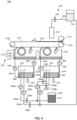
- the liquid application section 210 may include a plurality of receiving tanks 212 disposed at the respective cleaning positions, or may include one receiving tank 212 divided for each cleaning position (see Fig. 4 ).
- the concentrations of the cleaning liquids collected from the respective cleaning positions may be independently adjusted in the plurality of collection tanks 222 (see Fig. 4 ), or these cleaning liquids may be collectively adjusted in one collection tank 222.
- the liquid collection section 220 has a plurality of collection tanks 222. Then, the concentration adjusting section 230 adds the adjustment liquid 310 from the adjustment liquid tank 232 or the color ink from the ink tank 124 to the corresponding collection tank 222 in accordance with a ratio ( ⁇ collected liquid / ⁇ ink ) between the ⁇ collected liquid and ⁇ ink in respective collection tanks 222.
- a color ink in the ink tank 124 is added to the collection tank 222 to adjust the concentration of the cleaning liquid 300 in the embodiment described above
- a liquid having a high coloring agent concentration stored separately from the ink tank 124 may be added to the collection tank 222 to adjust the concentration of the cleaning liquid 300.
- the cleaning liquid 300 is applied to the conveyance belt 110 by ejection from the nozzle 211.
- a configuration may be used in which the rotating cleaning brush 214 contacts the cleaning liquid 300 stored in the receiving tank 212 and applies the cleaning liquid 300 adhering to the cleaning brush 214 to the conveyance belt 110.
- the reactive dye was changed to Reactive Yellow 95, Reactive Red 24, and Reactive Blue 72.
- Ink 2 to Ink 4 which were a yellow ink, a magenta ink, and a cyan ink, respectively, were obtained in the same manner as in the preparation of Ink 1 except the above.
- styrene-butyl acrylate-methacrylate co-polymer as a pigment-dispersing agent (anionic-dispersing agent, weight-average molecular weight: 16000, anionic-group equivalency: 3.5 meq/g) was mixed with 78 parts by mass of ion-exchanged water. Thereafter, the mixture was stirred with heating to prepare a neutralized product of a pigment-dispersing agent. To the mixed liquid, 15 parts by mass of black pigment (Pigment Black 7) was added and premixed, and then dispersed by using a sand grinder filled with 50% by volume fraction of 0. 5 mm zirconia beads, thereby obtaining a black pigment dispersion liquid with a pigment concentration of 15%.
- black pigment Pigment Black 7
- a surfactant Olelfine E1010, manufactured by Nissin Chemical Industries, Ltd
- a preservative manufactured by S. C. Johnson & Son
- Polyaluminum chloride (manufactured by Taki Chemical Co., Ltd., PAC250A) was used as an aggregating agent.
- Aluminum sulfate (manufactured by Taki Chemical Co., Ltd) was used.
- Ferric chloride (manufactured by Toagosei Co., Ltd) was used.
- Ferrous sulfate (Taki Chemical Co., Ltd) was used.
- a cationic polymer (PD-30, manufactured by Yokkaichi Gosei Co., Ltd) was used.
- As the organic polymer polyacrylamide (N-100T, manufactured by Taki Chemical Co., Ltd) and sodium polyacrylate (A-108T, manufactured by Taki Chemical Co., Ltd) were used.
- Tables 1 to 3 also show the pH of the cleaning liquid 1 to the cleaning liquid 12 measured with a pH meter (HM-41X, manufactured by TOA DEKA Corporation). Note that the unit of the ratio of each component described in Table 1 to Table 3 is mass%.
- each ink and one of the cleaning liquids 1 to 12 were mixed such that the concentration of the coloring agent was 0.5% by mass, to obtain corresponding one of samples 1 to 16.
- the absorbance, the degree of self-aggregation, and the degree of deterioration of the ground beam agent were evaluated by the following methods.
- Ion-exchanged water was added to each ink to a concentration of the coloring agent of 0.5% by mass to obtain a reference solution.
- the absorbance of each reference solution was measured with a spectrophotometer (V-500, manufactured by JASCO Corporation).
- the absorbance of the filtrates obtained by filtering Sample 1 to Sample 16 through filter paper (manufactured by Advantech Co., Ltd) were measured with the same spectrophotometer as that used for the measurement of the reference solutions.
- the absorbance ( ⁇ ink ) at the maximum absorption wavelength in the range of wavelengths 350 nm to 800 nm was measured for each reference solution obtained from the inks used in the preparation of the filtered samples for obtaining the filtrates.
- the absorbance (corresponding to ⁇ cleaning liquid ) at the same wavelength was measured for each filtrate. These were compared, and the absorbance was evaluated according to the following criteria.
- Sample 1 to Sample 16 were filtered through filter paper (manufactured by Advantech Co., Ltd) and whether or not self-aggregates of the aggregating agent were observed on the filter paper was visually observed to evaluate the degree of self-aggregation according to the following criteria.
- Samples 1 to 16 were used as cleaning liquids for the conveyor belt to which the ground beam agent had been applied, and corresponding inks 1 to 5 were filled in an image forming apparatus (manufactured by Konica Minolta, Inc., Nassenger 8). Solid printing was performed on a cotton broad recording medium 130 with each of the inks 1 to 5 for 1 hour per day, and the cleaning of the conveyance belt was performed for 3 months. After 3 months, the following were observed: the tackiness of the conveyance belt and how stable the conveyance of the fabric was. The deterioration of the ground beam agent was thus evaluated according to the following criteria.
- Table 4 indicates the types of ink and cleaning liquid used for the preparation and the evaluation results of the absorbance, the self-aggregation, and the degradation of the ground beam agent for Sample 1 to Sample 16.
- numerical values of ( ⁇ cleaning liquid / ⁇ ink ) for each sample are also indicated.
- the self-aggregation of the aggregating agent is suppressed by using the cleaning liquid in which the absorbance ratio ( ⁇ cleaning liquid / ⁇ ink ) is 0.01% or more and 50% or less.
- the cleaning liquid in which the absorbance ratio ( ⁇ cleaning liquid / ⁇ ink ) is 0.01% or more and 50% or less.
- the cleaning of the conveyance belt with the cleaning liquid can be more efficiently performed, and the reuse of the cleaning liquid can also be more efficiently performed.
- the reuse of the cleaning liquid becomes easy, it is possible to reduce the cost of waste liquid treatment, reduce environmental pollution due to waste liquid, and the like, and it becomes possible to easily perform image formation with ink even in a facility that does not have waste liquid treatment equipment. Therefore, the present invention is expected to greatly contribute to the spread of image formation with ink.
Landscapes
- Ink Jet (AREA)
- Ink Jet Recording Methods And Recording Media Thereof (AREA)
- Inks, Pencil-Leads, Or Crayons (AREA)
Abstract
Description
- The present invention relates to a cleaning method, an image forming method, a cleaning device, and an image forming apparatus.
- An image forming apparatus that forms an image with ink includes a conveyance belt that conveys a recording medium, and an image forming section that applies ink to the recording medium conveyed on the conveyance belt. The conveyance belt is contaminated with ink, waste paper and waste thread cut from the recording medium, dust in the air, and the like during image formation. To remove these contaminants, the conveyor belt is periodically cleaned.
- For example,
Japanese Unexamined Patent Publication No. 2022-083155 - As described in
Japanese Unexamined Patent Publication No. 2022-083155 Japanese Unexamined Patent Publication No. 2022-083155 - However, according to the findings of the present inventors, when the concentration of the aggregating agent in the cleaning liquid is increased in order to reliably remove the contaminants, self-aggregation of the aggregating agent occurs, and instead, the efficiency of removal of the contaminants from the cleaning liquid decreases. On the other hand, when the addition amount of the aggregating agent is suppressed in order to prevent the self-aggregation, the contaminants are not sufficiently aggregated, and the removal efficiency of the contaminants is not increased. In a case where the cleaning liquid that cannot sufficiently remove such a contaminant is reused, deterioration of the conveyance belt occurs due to the contaminant that cannot be completely removed.
- An object of the present invention is to provide a method of cleaning a conveyance belt, which can suppress self-aggregation of an aggregating agent added to a cleaning liquid, and also suppress deterioration of the conveyance belt due to a contaminant.
- One aspect of the present invention for solving the above-described problem relates to a conveyance belt cleaning method described in the following [1] to [10].
- [1] A method for cleaning a conveyance belt that is used to form an image on a recording medium conveyed on the conveyance belt by applying at least one type of color ink including a black ink to the recording medium, the method comprising:
- applying a cleaning liquid containing an inorganic aggregating agent to the conveyance belt from which the recording medium has moved to another member; and
- collecting the applied cleaning liquid, wherein
- in the applied cleaning liquid, a ratio (λ cleaning liquid/λ ink) of an absorbance (λ cleaning liquid), at a maximum absorption wavelength within a wavelength range of 350 nm or more and 800 nm or less, of a filtrate obtained by filtering the collected cleaning liquid to an absorbance (λink) of the black ink at the maximum absorption wavelength becomes 0.01% or more and 50% or less, the black ink having a concentration adjusted by adding ion-exchanged water so that a concentration of a coloring agent in the black ink becomes 0.5% by mass.
- [2] The cleaning method according to [1], wherein
The ratio (λ cleaning liquid/λ ink) is 0.1% or more and 30% or less. - [3] The cleaning method according to [1] or [2], wherein
the inorganic aggregating agent contained in the cleaning liquid is an inorganic aggregating agent selected from the group consisting of polyaluminum chloride, aluminum sulfate, ferric chloride, and ferrous sulfate. - [4] The cleaning method according to any one of [1] to [3], wherein
an amount of the inorganic aggregating agent is 0.01% by mass or more and 5% by mass or less based on a total mass of the cleaning liquid. - [5] The cleaning method according to any one of [1] to [4], wherein
the color ink is an ink containing a coloring agent selected from the group consisting of a reactive dye, a disperse dye, an acid dye, and a pigment. - [6] The cleaning method according to any one of [1] to [5], wherein
the cleaning liquid includes an organic polymer. - [7] The cleaning method according to [6], wherein
the organic polymer is polyacrylamide or sodium polyacrylate. - [8] The cleaning method according to any one of [1] to [7], wherein
the cleaning liquid has a pH of 4 or more and 6 or less. - [9] The cleaning method according to any one of [1] to [8], comprising:
filtering the collected cleaning liquid and adjusting a concentration of the filtered cleaning liquid; and
applying the cleaning liquid, whose concentration has been adjusted, to the conveyance belt. - [10] The cleaning method according to any one of [1] to [9], wherein
the recording medium is a fabric.
Another aspect of the present invention for solving the above-described problem relates to an image forming method described in the following [11]. - [11] An image forming method, comprising:
- conveying a recording medium on a conveyance belt;
- forming an image by applying at least one type of color ink including a black ink to the recording medium; and
- cleaning the conveyance belt, from which the recording medium has moved to another member, by the method according to any one of [1] to [10].
- [12] A cleaning device
- to be attached to an image forming apparatus that includes
- a conveyance belt that conveys a recording medium and an image forming section that forms an image on a recording medium conveyed on the conveyance belt by applying at least one type of color ink including a black ink to the recording medium, the cleaning device comprising:
- a liquid application section that applies a cleaning liquid to the conveyance belt;
- a liquid collection section that collects the applied cleaning liquid; and
- a concentration adjusting section that adjusts a concentration of the collected cleaning liquid in such a way that a ratio (λ cleaning iiquid/λ ink) of an absorbance (λ cleaning liquid), at a maximum absorption wavelength within a wavelength range of 350 nm or more and 800 nm or less, of a filtrate obtained by filtering the collected cleaning liquid to an absorbance (λ ink) of the black ink at the maximum absorption wavelength becomes 0.01% or more and 50% or less, the black ink having a concentration adjusted by adding ion-exchanged water so that a concentration of a coloring agent in the black ink becomes 0.5% by mass.
- [13] An image forming apparatus, comprising:
- a conveyance belt that conveys a recording medium;
- an image forming section that forms an image on a recording medium conveyed on the conveyance belt by applying at least one type of color ink including a black ink to the recording medium; and
- the cleaning device according to [12], the cleaning device cleaning the conveyance belt from which the recording medium has moved to another member.
a concentration measuring device that measures a concentration of the cleaning liquid collected by the liquid collection section. - The advantageous and features provided by one or more embodiments of the invention will become more fully understood from the detailed description given hereinbelow and the appended drawings which are given by way of illustration only, and thus are not intended as a definition of the limits of the present invention:
-
Fig. 1 is a schematic configuration diagram of an image forming apparatus according to an embodiment of the present invention; -
Fig. 2 is a flowchart illustrating steps of an image forming method using the image forming apparatus; -
Fig. 3 is a flowchart illustrating each sub-step of a cleaning step using the cleaning device, which is one step of the image forming method; and -
Fig. 4 is a schematic configuration diagram of an image forming apparatus according to another embodiment of the present invention. - Hereinafter, one or more embodiments of the present invention will be described with reference to the drawings. However, the scope of the invention is not limited to the disclosed embodiments.
-
Fig. 1 is a schematic configuration diagram of an image forming apparatus according to an embodiment of the present invention. - As illustrated in
Fig. 1 , theimage forming apparatus 100 includes aconveyance belt 110, animage forming section 120, and acleaning device 200 that cleans theconveyance belt 110. - The
conveyance belt 110 an endless belt member stretched around arotatable pulley 112a and arotatable pulley 112b. Next, theconveyance belt 110 is rotated in the conveyance direction X of therecording medium 130 by rotation of thepulleys rotatable feed roller 114 is disposed at a position opposing thepulley 112a on the upstream side in the conveyance direction X. Thefeed roller 114, together with thepulley 112a, holds theconveyance belt 110 and therecording medium 130 between thefeed roller 114 and thepulley 112a, and rotates to feed therecording medium 130 onto theconveyance belt 110. - In the present embodiment, the
recording medium 130 is a fabric on which an image is formed with water-based ink. A ground beam agent for fixing the fabric on the belt surface to stabilize the conveyance is applied to the surface of theconveyance belt 110 on the side where the cloth is supplied. Note that the type of therecording medium 130 is not particularly limited, and may be paper, a resin film, or the like. As the ground beam agent, a known ground beam agent such as a rubber-based ground beam agent containing natural rubber and synthetic rubber as main components, an acrylic-based ground beam agent containing an acrylic resin as a main component, or a silicon-based ground beam agent containing a silicon resin as a main component can be used. - The
image forming section 120 includes aninkjet head 122 that ejects water-based ink by an inkjet method. Theinkjet head 122 has a plurality of nozzles for ejecting ink droplets of color inks of respective colors of Y (yellow), M (magenta), C (cyan), and K (black) onto therecording medium 130. For example, theinkjet head 122 is configured to supply a plurality of types of ink having different colors to respective specific nozzles. Alternatively, theimage forming section 120 includes a plurality of inkjet heads 122 respectively corresponding to these colors. The one or plurality of inkjet heads 122 may be disposed so as to be capable of scanning in a direction crossing the conveyance direction X of therecording medium 130 on which an image is to be formed. - The
inkjet head 122 is supplied with ink in theink tank 124 via anink tube 126 connected to theink tank 124 and avalve 128. - In the present embodiment, the ink is an aqueous inkjet ink containing a coloring agent, an organic solvent, and water. The ink includes a color ink of a corresponding one of the colors of Y (yellow), M (magenta), C (cyan), and K (black) having different types of dyes. Note that the type of ink and the type of coloring agent included in the ink are not limited thereto. For example, the ink may be a solvent ink which contains an organic solvent but does not substantially contain water, or may be a curable ink which contains, as a liquid component, a curable composition which is polymerized by irradiation with active rays (such as ultraviolet rays or an electron beam). The type of the coloring material may be a dye such as a reactive dye, a disperse dye, or an acid dye, or may be a pigment.
- The
inkjet head 122 ejects ink droplets of the color inks of the respective colors onto therecording medium 130 to form an image of these inks on therecording medium 130. Note that theinkjet head 122 may eject and adhere clear ink onto therecording medium 130 separately from these color inks. - The
cleaning device 200 includes aliquid application section 210 that applies a cleaning liquid to theconveyance belt 110. Thecleaning device 200 includes aliquid collection section 220 that collects the applied cleaning liquid. Thecleaning device 200 includes aconcentration adjusting section 230 for adjusting the concentration of the collected cleaning liquid. Thecleaning device 200 includes aliquid supply section 240 that supplies the cleaning liquid whose concentration has been adjusted to theliquid application section 210. In thecleaning device 200, theliquid collection section 220 collects the cleaning liquid used for cleaning theconveyance belt 110 in theliquid application section 210 to remove contaminants, and then theliquid supply section 240 re-supplies the cleaning liquid to theliquid application section 210. By reusing the cleaning liquid in this manner, waste water treatment of the cleaning liquid becomes unnecessary, and thus it is possible to cut costs and reduce environmental pollution. - The
liquid application section 210 includes anozzle 211 that ejects a cleaning liquid 300 onto theconveyance belt 110, a receivingtank 212 that receives the cleaning liquid ejected from thenozzle 211, arotatable cleaning brush 214, and ascraper 219. The receivingtank 212 is a liquid tank that stores the cleaning liquid 300 dropped from the cleaningbrush 214 or thescraper 219 after being ejected from thenozzle 211 and used for cleaning. The receivingtub 212 is disposed at a position so that the cleaningbrush 214 does not contact the cleaning liquid 300 in the receivingtub 212. The cleaningbrush 214 includes acylindrical shaft portion 214a rotatable by a rotation mechanism (not illustrated) and a brush portion 214b formed of a large number of bristles radially disposed from an outer periphery of theshaft portion 214a. The cleaningbrush 214 is movable between a position at which the brush portion 214b is in contact with theconveyance belt 110 and a position at which the brush portion 214b is not in contact with theconveyance belt 110 by an elevating mechanism (not illustrated). Thescraper 219 is a plate-shaped member formed of an elastic member such as rubber or a synthetic resin such as polyethylene terephthalate (PET), and is disposed at a position so that a tip end thereof contacts theconveyance belt 110. - When the
conveyance belt 110 is cleaned, thenozzle 211 ejects the cleaning liquid 300 onto the surface of theconveyance belt 110. By the ejection of the cleaningliquid 300, in this manner, contaminants such as ink adhered to the surface of theconveyance belt 110, paper dust and thread dust cut from the recording medium, and dust in the air are removed from theconveyance belt 110. At this time, the cleaningbrush 214 is moved by the elevating mechanism to a position where the brush portion 214b contacts theconveyance belt 110. Then, when theshaft portion 214a is rotated by the rotation mechanism, the brush portion 214b rubs the surfaces of theconveyance belts 110 to which thecleaning liquid 300 is attached, thereby removing contaminants. Furthermore, thescraper 219 removes the contaminants and the cleaningliquid 300 remaining on the surface of theconveyance belt 110 from theconveyance belt 110. In this manner, the contaminants are removed from theconveyor belt 110 by thenozzle 211, the cleaningbrush 214, and thescraper 219. The removed contaminants are collected in the receivingtank 212. - The cleaning
liquid 300 is an aqueous liquid containing an aggregating agent that reacts with at least a part of the contaminants (for example, a coloring agent such as a dye or a pigment) to coagulate the contaminants, and water as a medium. - The aggregating agent is preferably an inorganic aggregating agent. Examples of the inorganic aggregating agent include polyaluminum chloride, aluminum sulfate, ferric chloride, ferrous sulfate, and polysilica iron. Of these, polyaluminum chloride, aluminum sulfate, ferric chloride, and ferrous sulfate are preferable, and ferric chloride is more preferable, because of their high aggregation effect. Although it is not clear whether these aggregating agents are effective in aggregation of contaminants such as a coloring agent (e.g., dye) contained in ink, according to the findings of the present inventor, these aggregating agents are also effective in aggregation of the coloring agent and the like. The content of the inorganic aggregating agent can be, for example, 0.1% by mass or more and 5% by mass or less based on the total mass of the cleaning liquid, and is preferably 0.5% by mass or more and 4% by mass or less. However, the content of the inorganic aggregating agent can be changed by concentration adjustment described below.
- The cleaning
liquid 300 may contain an organic polymer. By using the inorganic aggregating agent and the organic polymer in combination, the contaminant can be more efficiently aggregated. The organic polymer may be an anionic polymer, a cationic polymer, a nonionic polymer, or an amphoteric polymer. Examples of the anionic polymer include polyacrylamide and sodium polyacrylate. Examples of the cationic polymer include polyacrylamide, polyacrylate, polymethacrylate, polyamine, and polydicyandiamide. Examples of the nonionic polymer include polyacrylamide and polyethylene oxide. Examples of amphoteric polymers include dimethylaminoethyl acrylate. Of these, polyacrylamide and sodium polyacrylate are preferable because of their high aggregation effect, and the polyacrylamide is more preferably an anionic polymer. The content of the organic polymer can be, for example, 0.01% by mass or more and 2% by mass or less relative to the amount of the aggregating agent added, and is preferably 0.05% by mass or more and 1% by mass or less. Note that the content of the organic polymer can be changed by concentration adjustment described below. - The cleaning liquid 300 preferably has a pH of 4 or more and 6 or less. By making the cleaning liquid 300 acidic, self-aggregation of the inorganic aggregating agent can be made less likely to occur.
- The
liquid collection section 220 includes acollection tank 222 in which the collected cleaningliquid 300 is stored, and acollection channel 224 through which the cleaning liquid 300 in the receivingtank 212 is sent to thecollection tank 222 to be collected. Thecollection channel 224 is provided with acollection pump 226 that sends the cleaning liquid 300 from the receivingtank 212 to thecollection tank 222. Acollection filter 228 is installed at an inlet port of thecollection tank 222 through which the cleaning liquid 300 flows. - The
liquid collection section 220 recovers a part of the cleaning liquid 300 in the receivingtank 212 after cleaning theconveyance belt 110 or during cleaning to thecollection tank 222 through thecollection channel 224. At this time, thecollection filter 228 filters the cleaning liquid 300 in thecollection channel 224 to remove an aggregate of the contaminant aggregated by the aggregating agent. - Note that the
collection tank 222 may have a configuration in which the cleaning liquid 300 in thecollection tank 222 is stirred by a rotating stirring blade (not illustrated) or the like to make the concentration uniform. - The
concentration adjusting section 230 includes aconcentration measuring device 231 which measures the concentration of the cleaning liquid 300 in thecollection tank 222, and anadjustment liquid tank 232 which stores anadjustment liquid 310 which is a liquid having a low concentration of the aggregating agent. Theconcentration adjusting section 230 also includes anadjustment channel 234a that sends theadjustment liquid 310 in theadjustment liquid tank 232 to the inside of thecollection tank 222. Furthermore, theconcentration adjusting section 230 has anadjustment channel 234b that communicates with theink tank 124 and thecollection tank 222 to send a color ink (e.g., black ink) in theink tank 124 to the inside of thecollection tank 222. In theadjustment channel 234a, anadjustment pump 236a and anadjustment valve 238a are provided to send theadjustment liquid 310 from theadjustment liquid tank 232 to thecollection tank 222. In theadjustment channel 234b, anadjustment pump 236b and anadjustment value 238b are installed to send the ink from theink tank 124 to thecollection tank 222. - The
concentration measuring device 231 is, for example, a spectrophotometer that measures the absorbance at each wavelength of the cleaning liquid 300 in thecollection tank 222 or the cleaning liquid 300 extracted from thecollection tank 222. - The
concentration adjusting section 230 controls driving of theadjustment pump 236a and theadjustment pump 236b and opening and closing of theadjustment valve 238a and theadjustment valve 238b in accordance with the concentration of the cleaning liquid 300 measured by theconcentration measuring device 231. As a result, theadjustment liquid 310 in theadjustment liquid tank 232 or the ink in theink tank 124 is added to the cleaning liquid 300 in thecollection tank 222 to adjust the concentration of the cleaning liquid 300 to a predetermined range. - For example, when a fabric is used as the
recording medium 130, a ground beam agent may be applied to the surface of theconveyance belt 110 in order to stably convey the fabric. When the cleaning liquid 300 in which a large amount of dye as a contaminant remains is applied to such aconveyance belt 110, deterioration of the ground beam agent due to the dye tends to occur. In order to suppress such deterioration of theconveyance belt 110 due to the contaminant in the cleaningliquid 300 when the cleaningliquid 300 is reused for cleaning of theconveyance belt 110, it is considered desirable to more reliably remove the contaminant such as the dye from the cleaningliquid 300. In order to enhance the removal efficiency of the contaminant, it is sufficient to increase the concentration of the aggregating agent in the cleaning liquid 300 to facilitate the aggregation of the contaminant and enhance the removal efficiency of the contaminant (aggregate) by thecollection filter 228. - However, according to the findings of the present inventors, when the concentration of the aggregating agent is increased in order to increase the efficiency of removing contaminants from the cleaning
liquid 300, the efficiency of removing contaminants from the cleaningliquid 300 is conversely decreased. It is thought that this is because the aggregating agent ends up self-aggregation and it is not possible to sufficiently aggregate the contaminant. - The present inventors have studied a method for enhancing the efficiency of removing contaminants from the cleaning
liquid 300 on the basis of the above findings, and have found that the efficiency of removing contaminants is rather enhanced by intentionally allowing a small amount of contaminants to remain in the cleaningliquid 300. That is, the contaminant removal efficiency can be increased by increasing the concentration of the aggregating agent in the cleaning liquid 300 to the extent that the contaminants can be sufficiently coagulated and removed, but not to the extent that the contaminants are completely coagulated. - Specifically, for the black ink among the color inks ejected from the
inkjet head 122, ion-exchanged water is added to adjust the concentration of the coloring agent in the black ink to 0.5 mass%. The absorbance of the adjusted black ink at the maximum absorption wavelength in the range of wave lengths 350 nm to 800 nm is defined as λ ink. On the other hand, for the cleaning liquid 300 in the collection tank 222 (which is also the filtrate filtered by the collection filter 228), the absorbance at the same wavelength as the maximum absorption wavelength set for the black ink described above is defined as λ cleaning liquid. Note that the λ cleaning liquid is measured by theconcentration measuring device 231. Then, in thecleaning device 200 based on the above findings, theconcentration adjusting section 230 adjusts the concentration of the cleaning liquid 300 in thecollection tank 222 so that the ratio of the absorbance (λ cleaning liquid/λ ink) becomes 0.01% or more and 50% or less. - The ink applied to the
recording medium 130 is often a mixture of a plurality of colors (four colors of YMCK in the present embodiment). The coloring agent that adheres to theconveyance belt 110, is removed by the cleaningbrush 214, and is mixed in the cleaningliquid 300 is also often a mixture of the coloring agents included in these inks. Therefore, the color of the cleaning liquid 300 in which the mixture of these coloring agents is mixed is close to black. For this reason, the concentration of the coloring agent of the ink obtained by diluting the black ink ejected from theinkjet head 122 so that the concentration of the coloring agent becomes 0.5 mass% is used as an index indicating the amount of the coloring agent as a contaminant contained in the cleaningliquid 300. The concentration of the coloring agent in the diluted ink is indicated by the absorbance λink. - In the cleaning
liquid 300, the coloring agent as the contaminant is aggregated by the aggregating agent and removed. Therefore, the concentration of the coloring agent in the cleaning liquid 300 (indicated by absorbance λ cleaning liquid) is lower (smaller) than λink. At this time, when the concentration of the aggregating agent in the cleaningliquid 300 is reduced to the extent that the ratio (λ cleaning liquid/λ ink) becomes 0.01% or more, self-aggregation of the aggregating agent is less likely to occur, and the efficiency of removing contaminants from the cleaningliquid 300 is increased. On the other hand, when the concentration of the aggregating agent in the cleaningliquid 300 is increased to such an extent that the ratio (λ cleaning liquid/λ ink) becomes 50% or less, the contaminants are sufficiently coagulated by the aggregating agent, and the efficiency of removing the contaminants from the cleaningliquid 300 is increased. From the above viewpoint, the ratio (λ cleaning liquid/λink) is preferably 0.1% or more and 30% or less, and more preferably 0.1% or more and 10% or less. - Note that the absorbance λ cleaning liquid may change depending on the type or combination of aggregating agents, and can also change depending on the concentration or the like of the coloring agent of the ink used for image formation. Therefore, the concentration of the aggregating agent for achieving the absorbance λ cleaning liquid in which the removal efficiency of the contaminant is increased is not necessarily a constant concentration. On the other hand, in the present embodiment, since the concentration of the cleaning
liquid 300 is adjusted by the absorbance λ cleaning liquid measured from the cleaningliquid 300 and the absorbance λ ink measured from the ink, the efficiency of removing the contaminants from the cleaning liquid 300 can be increased without being limited to the above-described changes. - In the present embodiment, the
concentration measuring device 231 measures the absorbance λ collected liquid of the cleaning liquid 300 stored in thecollection tank 222 after the contaminants are removed by thecollection filter 228. When the ratio of λ collected liquid and λ ink (λ collected liquid/λ ink) is higher than the above range (higher than 50%), theconcentration adjusting section 230 determines that the concentration of the aggregating agent in the cleaningliquid 300 is excessively low. Then, theadjustment pump 236a is driven, theadjustment valve 238a is opened, and theadjustment liquid 310 having a high concentration of the aggregating agent stored in theadjustment liquid tank 232 is added to thecollection tank 222. As a result, the contaminants can be sufficiently aggregated in the cleaningliquid 300 after the next cleaning, and the removal efficiency of the contaminants can be increased. On the other hand, when the ratio of λ collected liquid and λ ink (λ collected liquid/λ ink) is lower than the above range (lower than 0.01%), theconcentration adjusting section 230 determines that the concentration of the aggregating agent in the cleaningliquid 300 is excessively high. Then, thecontrol pump 236b is driven and theadjustment valve 238b is opened to add the ink from theink tank 124 to thecollection tank 222. Thus, the concentration of the coloring agent in the cleaning liquid is increased, and the coloring agent and the aggregating agent are allowed to react with each other to decrease the concentration of the aggregating agent. In this manner, the self-aggregation of the aggregating agent can be suppressed, and the efficiency of removing contaminants from the cleaningliquid 300 after the next cleaning can be increased. - In this manner, the
concentration adjusting section 230 adjusts the concentration of the cleaning liquid 300 in thecollection tank 222 so that λ collected liquid/λ ink is in the above-described range. - The
liquid supply section 240 includes asupply channel 244 for supplying the cleaningliquid 300, whose concentration has been adjusted in thecollection tank 222, to thenozzle 211. In thesupply channel 244, asupply pump 246 and asupply filter 248 are installed that send the cleaning liquid 300 from thecollection tank 222 to thenozzle 211. - The
liquid supply section 240 supplies a part of the cleaningliquid 300, whose concentration is adjusted by theconcentration adjusting section 230, to thenozzle 211 through thesupply channel 244. At this time, thesupply filter 248 filters the cleaning liquid 300 in thesupply channel 244 to remove unwanted substances. In addition, since the aggregate of the coloring agent which affects the absorbance is removed by thecollection filter 228 of thecollection channel 224, λ collected liquid are basically not changed even after the passage through thesupply filter 248. - In this manner, reusing the cleaning liquid, in which the concentration is adjusted so that the ratio of λ collected liquid and λ ink (λ collected liquid/λ ink) is in a predetermined range, allows the cleaning liquid to be used for cleaning the
conveyance belt 110, thereby efficiently removing the contaminants. -
Fig. 2 is a flowchart illustrating steps of an image forming method using the above-describedimage forming apparatus 100.Fig. 3 is a flowchart illustrating each sub-step of a cleaning step using thecleaning device 200 described above, which is one step of the image forming method. - As illustrated in
Fig. 2 ,image forming apparatus 100 first conveysrecording medium 130 onto conveyance belt 110 (step S110). - Then, ink is applied to the conveyed
recording medium 130 to form an image (step S120). Specifically, the ink of each color of YMCK is applied to a predetermined position on therecording medium 130 while theinkjet head 122 is scanned in a direction intersecting the conveyance direction X of therecording medium 130 as necessary. - After the
recording medium 130 is moved from theconveyance belt 110 to another member, theconveyance belt 110 is cleaned (step S130). - As illustrated in
Fig. 3 , in the cleaning step (step S130), thecleaning device 200 first applies the cleaning liquid to theconveyance belt 110 to clean the conveyance belt 110 (step S210). Specifically, theliquid application section 210 ejects the cleaning liquid 300 from thenozzle 211 onto the surface of theconveyance belt 110. Further, theliquid application section 210 moves the cleaningbrush 214 to a position where the brush portion 214b contacts theconveyance belt 110 by the elevating mechanism. Next, theliquid application section 210 rotates theshaft portion 214a of the cleaningbrush 214 by the rotation mechanism, to frictionally slide the brush portion 214b on theconveyance belt 110. By the ejection of the cleaning liquid 300 from thenozzle 211, the rubbing of the brush portion 214b of the cleaningbrush 214, and the contact of thescraper 219, theliquid application section 210 removes contaminants from theconveyance belt 110. The removed contaminants drop into the receivingtank 212 together with the cleaningliquid 300. - When the cleaning liquid used by the
liquid application section 210 is reused (step S220, YES), theliquid collection section 220 removes the aggregated contaminants from the cleaning liquid 300 in the receivingtank 212 and collects the contaminants in the collecting tank 222 (step S230). Specifically, theliquid collection section 220 drives thecollection pump 226 to cause the cleaning liquid 300 in the receivingtank 212 to flow through thecollection channel 224, removes aggregates of contaminants by thecollection filter 228, and stores the cleaning liquid in thecollection tank 222. - Next, the
concentration adjusting section 230 adjusts the concentration of the cleaning liquid 300 in the collection tank 222 (step S240). Specifically, theconcentration adjusting section 230 measures the concentration (absorbance for each wavelength) of the cleaning liquid 300 in thecollection tank 222 by theconcentration measuring device 231. When the concentration of the aggregating agent in the cleaningliquid 300 is higher than the predetermined range, theconcentration adjusting section 230 adds theadjustment liquid 310 having a high concentration of the aggregating agent to thecollection tank 222. The concentration of the aggregating agent in the cleaningliquid 300 is an absorbance at the maximum absorption wavelength of the black ink. The predetermined range of the concentration of the aggregating agent is a range in which λ cleaning liquid/λ ink is 0.01% or more and 50% or less. When the concentration of the aggregating agent in the cleaningliquid 300 is lower than the predetermined range, theconcentration adjusting section 230 adds color ink to thecollection tank 222. In this manner, theconcentration adjusting section 230 adjusts the concentration of the cleaning liquid 300 in thecollection tank 222 to fall in a range in which λ cleaning liquid/λ ink is 0.01% or more and 50% or less. - Next, the
liquid supplying section 240 supplies the cleaningliquid 300, whose concentration is adjusted by theconcentration adjusting section 230, to the nozzle 211 (step S250). Specifically, theliquid supply section 240 circulates the cleaning liquid 300 in thecollection tank 222 to thesupply channel 244 by driving thesupply pump 246, removes unnecessary substances by thesupply filter 248, and supplies the cleaning liquid to thenozzle 211. - Then, the
liquid application section 210 applies (ejects) the supplied cleaning liquid 300 to theconveyance belt 110 from thenozzle 211 to clean the conveyance belt 110 (step S210). - When the cleaning liquid used by the
liquid application section 210 is not reused, such as when the cleaning step is finished (step S220, NO), these steps are not performed. - As described above, in the present embodiment, the concentration of the cleaning liquid, from which the aggregates of contaminants have been removed by the
collection filter 228, is adjusted so as to satisfy the above-described absorbance ratio. Then, the cleaning liquid of which the concentration is adjusted is applied to the conveyance belt for cleaning the conveyance belt. Thus, it is possible to increase the efficiency of removing the collected contaminant even when the cleaning liquid is reused. - Note that the above-described embodiment is merely an example, and it is needless to say that appropriate modifications are possible within the scope of the technical idea of the present invention.
- For example, in the above-described embodiment, an image is formed by using four color inks of YMCK, but an image may be formed by using only one color of black ink.
- Furthermore, although the cleaning liquid is reused in the above-described embodiment, the used cleaning liquid may be subjected to drainage treatment without reusing the cleaning liquid. In this case as well, by making the cleaning liquid applied to the conveyance belt satisfy the above-described absorbance ratio, it is possible to increase the efficiency of removing contaminants from the cleaning liquid during waste liquid treatment.
- Furthermore, as illustrated in
Fig. 4 , theliquid application section 210 may clean the surface of theconveyance belt 110 at a plurality of positions with a plurality ofnozzles 211, a plurality of cleaning brushes 214, and a plurality ofscrapers 219. At this time, theliquid application section 210 may include a plurality of receivingtanks 212 disposed at the respective cleaning positions, or may include onereceiving tank 212 divided for each cleaning position (seeFig. 4 ). At this time, the concentrations of the cleaning liquids collected from the respective cleaning positions may be independently adjusted in the plurality of collection tanks 222 (seeFig. 4 ), or these cleaning liquids may be collectively adjusted in onecollection tank 222. In the configuration illustrated inFig. 4 , theliquid collection section 220 has a plurality ofcollection tanks 222. Then, theconcentration adjusting section 230 adds theadjustment liquid 310 from theadjustment liquid tank 232 or the color ink from theink tank 124 to thecorresponding collection tank 222 in accordance with a ratio (λ collected liquid/λ ink) between the λ collected liquid and λ ink inrespective collection tanks 222. - Furthermore, although a color ink in the
ink tank 124 is added to thecollection tank 222 to adjust the concentration of the cleaning liquid 300 in the embodiment described above, a liquid having a high coloring agent concentration stored separately from theink tank 124 may be added to thecollection tank 222 to adjust the concentration of the cleaningliquid 300. - Furthermore, in the embodiment described above, the cleaning
liquid 300 is applied to theconveyance belt 110 by ejection from thenozzle 211. However, a configuration may be used in which therotating cleaning brush 214 contacts the cleaning liquid 300 stored in the receivingtank 212 and applies the cleaningliquid 300 adhering to the cleaningbrush 214 to theconveyance belt 110. - Hereinafter, the present invention will be specifically described with reference to Examples, but the scope of the present invention is not limited to the description of Examples.
- To the preparation container, 20% by mass of ethylene glycol and 10 parts by mass of glycerin were added. In addition, 20 parts by mass of a reactive dye (Reactive Black 5) were added. Then, 0.05 parts by mass of a surfactant (Olfine E1010, manufactured by Nissin Chemical Industry Co., Ltd., "Olfine" is a registered trademark of the company) was added. Then, 0.2 parts by mass of a preservative (Proxel GXL, manufactured by S. C. Johnson & Son) was added. Ion-exchanged water was further added thereto so that the total amount became 100 parts by mass, followed by mixing and sufficient stirring. The aqueous solution obtained by the stirring was filtered through a 1-µm (pore size) filter to obtain ink 1, which is a black ink.
- The reactive dye was changed to Reactive Yellow 95, Reactive Red 24, and Reactive Blue 72. Ink 2 to Ink 4, which were a yellow ink, a magenta ink, and a cyan ink, respectively, were obtained in the same manner as in the preparation of Ink 1 except the above.
- Seven parts by mass of styrene-butyl acrylate-methacrylate co-polymer as a pigment-dispersing agent (anionic-dispersing agent, weight-average molecular weight: 16000, anionic-group equivalency: 3.5 meq/g) was mixed with 78 parts by mass of ion-exchanged water. Thereafter, the mixture was stirred with heating to prepare a neutralized product of a pigment-dispersing agent. To the mixed liquid, 15 parts by mass of black pigment (Pigment Black 7) was added and premixed, and then dispersed by using a sand grinder filled with 50% by volume fraction of 0. 5 mm zirconia beads, thereby obtaining a black pigment dispersion liquid with a pigment concentration of 15%.
- Added were 10 parts by mass of the black pigment dispersion liquid, 20 parts by mass of ethylene glycol, 10 parts by mass of glycerin, 0.05 parts by mass of a surfactant (Olfine E1010, manufactured by Nissin Chemical Industries, Ltd), and 0.2 parts by mass of a preservative (Proxel GXL, manufactured by S. C. Johnson & Son). Ion exchanged water was further added thereto so that the total amount became 100 parts by mass, mixed, and sufficiently stirred to obtain ink 5, which is a black ink.
- Polyaluminum chloride (manufactured by Taki Chemical Co., Ltd., PAC250A) was used as an aggregating agent. Aluminum sulfate (manufactured by Taki Chemical Co., Ltd) was used. Ferric chloride (manufactured by Toagosei Co., Ltd) was used. Ferrous sulfate (Taki Chemical Co., Ltd) was used. A cationic polymer (PD-30, manufactured by Yokkaichi Gosei Co., Ltd) was used. As the organic polymer, polyacrylamide (N-100T, manufactured by Taki Chemical Co., Ltd) and sodium polyacrylate (A-108T, manufactured by Taki Chemical Co., Ltd) were used. These materials, sodium hydroxide, and ion exchanged water were mixed in the proportions listed in Table 1 to Table 3 to obtain cleaning liquid 1 to cleaning liquid 12. Tables 1 to 3 also show the pH of the cleaning liquid 1 to the cleaning liquid 12 measured with a pH meter (HM-41X, manufactured by TOA DEKA Corporation). Note that the unit of the ratio of each component described in Table 1 to Table 3 is mass%.
[Table 1] Cleaning liquid 1 Cleaning liquid 2 Cleaning liquid 3 Cleaning liquid 4 Aggregating agent Polyaluminum chloride 4 Aluminum sulfate 4 Ferric chloride 4 Ferrous sulfate 4 Cationic polymer Organic polymer Polyacrylamide Sodium polyacrylate Sodium hydroxide 0.5 0.5 0.5 0.5 Ion-exchanged water Remaining part Remaining part Remaining part Remaining part Total 100 100 100 100 pH 6.5 6.5 6.5 6.5 [Table 2] Cleaning liquid 5 Cleaning liquid 6 Cleaning liquid 7 Cleaning liquid 8 Aggregatin g agent Polyaluminum chloride 4 4 1 4 Aluminum sulfate Ferric chloride Ferrous sulfate Cationic polymer Organic polymer Polyacrylamide 0.004 Sodium polyacrylate 0.004 Sodium hydroxide 0.5 0.5 0.1 0.2 Ion-exchanged water Remaining part Remaining part Remaining part Remaining part Total 100 100 100 100 pH 6.5 6.5 6.5 5.0 [Table 3] Cleaning liquid 9 Cleaning liquid 10 Cleaning liquid 11 Cleaning liquid 12 Aggregatin g agent Polyaluminum chloride 1 8 0.005 Aluminum sulfate Ferric chloride Ferrous sulfate Cationic polymer 4 Organic polymer Polyacrylamide 0.001 Sodium polyacrylate Sodium hydroxide 0.05 1 Ion-exchanged water Remaining part Remaining part Remaining part Remaining part Total 100 100 100 100 pH 5.0 7.0 6.5 6.5 - Each ink and one of the cleaning liquids 1 to 12 were mixed such that the concentration of the coloring agent was 0.5% by mass, to obtain corresponding one of samples 1 to 16. With respect to Samples 1 to 16, the absorbance, the degree of self-aggregation, and the degree of deterioration of the ground beam agent were evaluated by the following methods.
- Ion-exchanged water was added to each ink to a concentration of the coloring agent of 0.5% by mass to obtain a reference solution. The absorbance of each reference solution was measured with a spectrophotometer (V-500, manufactured by JASCO Corporation). The absorbance of the filtrates obtained by filtering Sample 1 to Sample 16 through filter paper (manufactured by Advantech Co., Ltd) were measured with the same spectrophotometer as that used for the measurement of the reference solutions.
- The absorbance (λ ink) at the maximum absorption wavelength in the range of wavelengths 350 nm to 800 nm was measured for each reference solution obtained from the inks used in the preparation of the filtered samples for obtaining the filtrates. The absorbance (corresponding to λ cleaning liquid) at the same wavelength was measured for each filtrate. These were compared, and the absorbance was evaluated according to the following criteria.
- A: The absorbance of λ cleaning liquid is 0.1% or more and 50% or less with respect to the absorbance of λink.
- B: A cleaning liquid is less than 0.1% or greater than 50% of the absorbance of λ ink.
- Sample 1 to Sample 16 were filtered through filter paper (manufactured by Advantech Co., Ltd) and whether or not self-aggregates of the aggregating agent were observed on the filter paper was visually observed to evaluate the degree of self-aggregation according to the following criteria.
- A: No self-aggregate is found on filter paper
- B: A slight amount of self-aggregates is observed on filter paper
- C: A certain amount of self-aggregates is observed on filter paper
- D: A significant amount of self-aggregates is observed on the filter paper
- Samples 1 to 16 were used as cleaning liquids for the conveyor belt to which the ground beam agent had been applied, and corresponding inks 1 to 5 were filled in an image forming apparatus (manufactured by Konica Minolta, Inc., Nassenger 8). Solid printing was performed on a cotton
broad recording medium 130 with each of the inks 1 to 5 for 1 hour per day, and the cleaning of the conveyance belt was performed for 3 months. After 3 months, the following were observed: the tackiness of the conveyance belt and how stable the conveyance of the fabric was. The deterioration of the ground beam agent was thus evaluated according to the following criteria. - A: The tackiness after 3 months was similar to the initial stickiness, allowing the fabric to be conveyed stably
- B: The tackiness after 3 months was slightly lower than the initial tackiness, but the fabric could be conveyed stably
- C: The tackiness after 3 months was much lower than the initial tackiness, and the fabric could not be conveyed stably
- Table 4 indicates the types of ink and cleaning liquid used for the preparation and the evaluation results of the absorbance, the self-aggregation, and the degradation of the ground beam agent for Sample 1 to Sample 16. In the column of absorbance, numerical values of (λ cleaning liquid/λ ink) for each sample are also indicated.
[Table 4] Sample No Ink No Cleaning liquid No Absorbance Self-aggregation Degradation of ground beam agent Remarks Sample 1 Ink 1 Cleaning liquid 1 A (5%) C B Example Sample 2 Ink 1 Cleaning liquid 2 A (5%) C B Example Sample 3 Ink 1 Cleaning liquid 3 A (5%) C B Example Sample 4 Ink 1 Cleaning liquid 4 A (5%) C B Example Sample 5 Ink 1 Cleaning liquid 5 A (2%) C B Example Sample 6 Ink 1 Cleaning liquid 6 A (2%) C B Example Sample 7 Ink 1 Cleaning liquid 7 A (5%) B B Example Sample 8 Ink 1 Cleaning liquid 8 A (5%) A B Example Sample 9 Ink 1 Cleaning liquid 9 A (5%) A A Example Sample 10 Ink 1 Cleaning liquid 10 A (45%) C B Example Sample 11 Ink 2 Cleaning liquid 9 A (5%) A A Example Sample 12 Ink 3 Cleaning liquid 9 A (5%) A A Example Sample 13 Ink 4 Cleaning liquid 9 A (5%) A A Example Sample 14 Ink 5 Cleaning liquid 9 A (10%) A A Example sample 15 Ink 1 Cleaning liquid 11 B (0.05%) D A Comparative example Sample 16 Ink 1 Cleaning liquid 12 B (80%) C C Comparative example - As is clear from Table 4, the self-aggregation of the aggregating agent is suppressed by using the cleaning liquid in which the absorbance ratio (λ cleaning liquid/λ ink) is 0.01% or more and 50% or less. In addition, it is possible to suppress deterioration of the conveyance belt (ground beam agent) due to the coloring agent which is not completely removed due to aggregation.
- According to the present invention, the cleaning of the conveyance belt with the cleaning liquid can be more efficiently performed, and the reuse of the cleaning liquid can also be more efficiently performed. When the reuse of the cleaning liquid becomes easy, it is possible to reduce the cost of waste liquid treatment, reduce environmental pollution due to waste liquid, and the like, and it becomes possible to easily perform image formation with ink even in a facility that does not have waste liquid treatment equipment. Therefore, the present invention is expected to greatly contribute to the spread of image formation with ink.
-
- 100 Image forming apparatus
- 110 Conveyance belt
- 112A, 112B Pulley
- 114 Feed roller
- 120 Image forming section
- 122 Inkjet head
- 124 Ink tank
- 126 Ink tube
- 128 Valve
- 130 Recording medium
- 200 Cleaning device
- 210 Liquid application section
- 211 Nozzle
- 212 Receiving tank
- 214 Cleaning brush
- 214A Shaft portion
- 214B Brush portion
- 219 Scraper
- 220 Liquid collection section
- 222 Collection tank
- 224 Collection channel
- 226 Collection pump
- 228 Collection filter
- 230 Concentration adjusting section
- 232 Adjustment liquid tank
- 234A, 234B Adjustment channel
- 236A, 236B Adjustment pump
- 238A, 238B Adjustment valve
- 240 Liquid supply section
- 244 Supply channel
- 246 Supply pump
- 248 Supply filter
- 300 Cleaning liquid
- 310 Adjustment liquid
- Although embodiments of the present invention have been described and illustrated in detail, it is clearly understood that the same is by way of illustration and example only and not limitation, the scope of the present invention should be interpreted by terms of the appended claims.
Claims (14)
- A method for cleaning a conveyance belt that is used to form an image on a recording medium conveyed on the conveyance belt by applying at least one type of color ink including a black ink to the recording medium, the method comprising:applying a cleaning liquid containing an inorganic aggregating agent to the conveyance belt from which the recording medium has moved to another member; andcollecting the applied cleaning liquid, whereinin the applied cleaning liquid, a ratio (λ cleaning liquid/λ ink) of an absorbance (λ cleaning liquid), at a maximum absorption wavelength within a wavelength range of 350 nm or more and 800 nm or less, of a filtrate obtained by filtering the collected cleaning liquid to an absorbance (λ ink) of the black ink at the maximum absorption wavelength becomes 0.01% or more and 50% or less, the black ink having a concentration adjusted by adding ion-exchanged water so that a concentration of a coloring agent in the black ink becomes 0.5% by mass.
- The method according to claim 1, wherein
the ratio (λ cleaning liquid/λ ink) is 0.1% or more and 30% or less. - The method according to claim 1 or 2, wherein
the inorganic aggregating agent contained in the cleaning liquid is an inorganic aggregating agent selected from the group consisting of polyaluminum chloride, aluminum sulfate, ferric chloride, and ferrous sulfate. - The method according to any one of claims 1 to 3, wherein
an amount of the inorganic aggregating agent is 0.01% by mass or more and 5% by mass or less based on a total mass of the cleaning liquid. - The method according to any one of claims 1 to 4, wherein
the color ink is an ink containing a coloring agent selected from the group consisting of a reactive dye, a disperse dye, an acid dye, and a pigment. - The method according to any one of claims 1 to 5, wherein
the cleaning liquid includes an organic polymer. - The method according to claim 6, wherein
the organic polymer is polyacrylamide or sodium polyacrylate. - The method according to any one of claims 1 to 7, wherein
the cleaning liquid has a pH of 4 or more and 6 or less. - The method according to any one of claims 1 to 8, further comprising:filtering the collected cleaning liquid and adjusting a concentration of the filtered cleaning liquid; andapplying the cleaning liquid, whose concentration has been adjusted, to the conveyance belt.
- The method according to any one of claims 1 to 9, wherein
the recording medium is a fabric. - An image forming method, comprising:conveying a recording medium on a conveyance belt;forming an image by applying at least one type of color ink including a black ink to the recording medium; andcleaning the conveyance belt, from which the recording medium has moved to another member, by the method according to any one of claims 1 to 10.
- A cleaning device to be attached to an image forming apparatus that includes
a conveyance belt that conveys a recording medium and an image forming section that forms an image on a recording medium conveyed on the conveyance belt by applying at least one type of color ink including a black ink to the recording medium, the cleaning device comprising:a liquid application section that applies a cleaning liquid to the conveyance belt;a liquid collection section that collects the applied cleaning liquid; anda concentration adjusting section that adjusts a concentration of the collected cleaning liquid in such a way that a ratio (λ cleaning liquid/λ ink) of an absorbance (λ cleaning liquid), at a maximum absorption wavelength within a wavelength range of 350 nm or more and 800 nm or less, of a filtrate obtained by filtering the collected cleaning liquid to an absorbance (λ ink) of the black ink at the maximum absorption wavelength becomes 0.01% or more and 50% or less, the black ink having a concentration adjusted by adding ion-exchanged water so that a concentration of a coloring agent in the black ink becomes 0.5% by mass. - An image forming apparatus, comprising:a conveyance belt that conveys a recording medium;an image forming section that forms an image on a recording medium conveyed on the conveyance belt by applying at least one type of color ink including a black ink to the recording medium; andthe cleaning device according to claim 12, the cleaning device cleaning the conveyance belt from which the recording medium has moved to another member.
- The image forming apparatus according to claim 13, further comprising:
a concentration measuring device that measures a concentration of the cleaning liquid collected by the liquid collection section.
Applications Claiming Priority (1)
| Application Number | Priority Date | Filing Date | Title |
|---|---|---|---|
| JP2023104168A JP2025004463A (en) | 2023-06-26 | 2023-06-26 | Cleaning method, image forming method, cleaning device and image forming device |
Publications (1)
| Publication Number | Publication Date |
|---|---|
| EP4484173A1 true EP4484173A1 (en) | 2025-01-01 |
Family
ID=91664636
Family Applications (1)
| Application Number | Title | Priority Date | Filing Date |
|---|---|---|---|
| EP24183989.3A Pending EP4484173A1 (en) | 2023-06-26 | 2024-06-24 | Cleaning method, image forming method, cleaning device, and image forming apparatus |
Country Status (2)
| Country | Link |
|---|---|
| EP (1) | EP4484173A1 (en) |
| JP (1) | JP2025004463A (en) |
Citations (4)
| Publication number | Priority date | Publication date | Assignee | Title |
|---|---|---|---|---|
| JP2011201125A (en) * | 2010-03-25 | 2011-10-13 | Fujifilm Corp | Ink jet recorder and ink jet recording method |
| JP2015186906A (en) * | 2014-03-13 | 2015-10-29 | 株式会社リコー | Cleaning liquid |
| US20160160161A1 (en) * | 2012-02-01 | 2016-06-09 | Takashi Tamai | Cleaning filling liquid, cartridge, cleaning filling method, and inkjet recording device |
| US20220161581A1 (en) * | 2020-11-24 | 2022-05-26 | Seiko Epson Corporation | Printing system, treatment apparatus, and method of reusing cleaning liquid |
-
2023
- 2023-06-26 JP JP2023104168A patent/JP2025004463A/en active Pending
-
2024
- 2024-06-24 EP EP24183989.3A patent/EP4484173A1/en active Pending
Patent Citations (5)
| Publication number | Priority date | Publication date | Assignee | Title |
|---|---|---|---|---|
| JP2011201125A (en) * | 2010-03-25 | 2011-10-13 | Fujifilm Corp | Ink jet recorder and ink jet recording method |
| US20160160161A1 (en) * | 2012-02-01 | 2016-06-09 | Takashi Tamai | Cleaning filling liquid, cartridge, cleaning filling method, and inkjet recording device |
| JP2015186906A (en) * | 2014-03-13 | 2015-10-29 | 株式会社リコー | Cleaning liquid |
| US20220161581A1 (en) * | 2020-11-24 | 2022-05-26 | Seiko Epson Corporation | Printing system, treatment apparatus, and method of reusing cleaning liquid |
| JP2022083155A (en) | 2020-11-24 | 2022-06-03 | セイコーエプソン株式会社 | How to reuse printing systems, processing equipment, and cleaning fluids |
Also Published As
| Publication number | Publication date |
|---|---|
| JP2025004463A (en) | 2025-01-15 |
Similar Documents
| Publication | Publication Date | Title |
|---|---|---|
| EP3397703B1 (en) | Water-based pigment dispersion | |
| JP5146041B2 (en) | Inkjet printer and inkjet head cleaning liquid | |
| JP2024064859A (en) | Inkjet ink and inkjet recording device | |
| EP2495290B1 (en) | Aqueous dispersion for inkjet printing | |
| JP7379038B2 (en) | Inkjet recording method and inkjet recording device | |
| JP2024014320A (en) | Inkjet ink and inkjet recording device | |
| US7407537B2 (en) | Ink set for ink-jet recording, method for producing the same, and the ink-jet printer | |
| EP3061616B1 (en) | Ink-jet recording apparatus and accumulation supressing method | |
| US6793724B2 (en) | Ink for ink-jet recording and color ink set | |
| JP2024014319A (en) | Inkjet ink and inkjet recording equipment | |
| JP7379037B2 (en) | Inkjet recording method and inkjet recording device | |
| JP2025004463A (en) | Cleaning method, image forming method, cleaning device and image forming device | |
| JP6646869B2 (en) | Ink set for inkjet recording | |
| JP2025012457A (en) | Inkjet ink and inkjet recording device | |
| JP2016215385A (en) | Repairing method of recording head, and ink jet recording device | |
| CN117624969A (en) | Water-based inkjet ink composition and inkjet recording method | |
| JP6319177B2 (en) | Recording head repair method and ink jet recording apparatus | |
| JP7234508B2 (en) | Water-based ink for inkjet recording | |
| JP7427407B2 (en) | Inkjet recording method and inkjet recording device | |
| EP2505621B1 (en) | Treatment solution for ink-jet recording, water-based ink set for ink-jet recording, ink-jet recording method, and ink jet recording apparatus | |
| EP2505620B1 (en) | Water-based ink for ink-jet recording, ink cartridge, water-based ink set for ink-jet recording, ink-jet recording method, and ink-jet recording apparatus | |
| CN102653169B (en) | Examination method and manufacture method for shower nozzle for water-based ink and shower nozzle for treating fluid, and examination fluid | |
| EP3061617B1 (en) | Ink-jet recording apparatus and accumulation suppressing method | |
| WO2024070936A1 (en) | Cleaning liquid for inkjet recording devices | |
| JP2003182097A (en) | Inkjet recorder and method of inkjet recording |
Legal Events
| Date | Code | Title | Description |
|---|---|---|---|
| PUAI | Public reference made under article 153(3) epc to a published international application that has entered the european phase |
Free format text: ORIGINAL CODE: 0009012 |
|
| STAA | Information on the status of an ep patent application or granted ep patent |
Free format text: STATUS: THE APPLICATION HAS BEEN PUBLISHED |
|
| AK | Designated contracting states |
Kind code of ref document: A1 Designated state(s): AL AT BE BG CH CY CZ DE DK EE ES FI FR GB GR HR HU IE IS IT LI LT LU LV MC ME MK MT NL NO PL PT RO RS SE SI SK SM TR |
|
| P01 | Opt-out of the competence of the unified patent court (upc) registered |
Free format text: CASE NUMBER: APP_17959/2025 Effective date: 20250414 |
|
| STAA | Information on the status of an ep patent application or granted ep patent |
Free format text: STATUS: REQUEST FOR EXAMINATION WAS MADE |
|
| 17P | Request for examination filed |
Effective date: 20250625 |
|
| GRAP | Despatch of communication of intention to grant a patent |
Free format text: ORIGINAL CODE: EPIDOSNIGR1 |
|
| STAA | Information on the status of an ep patent application or granted ep patent |
Free format text: STATUS: GRANT OF PATENT IS INTENDED |