EP4484142A1 - Pneumatic tire, puncture repair method for pneumatic tire, and vehicle - Google Patents
Pneumatic tire, puncture repair method for pneumatic tire, and vehicle Download PDFInfo
- Publication number
- EP4484142A1 EP4484142A1 EP24165913.5A EP24165913A EP4484142A1 EP 4484142 A1 EP4484142 A1 EP 4484142A1 EP 24165913 A EP24165913 A EP 24165913A EP 4484142 A1 EP4484142 A1 EP 4484142A1
- Authority
- EP
- European Patent Office
- Prior art keywords
- tire
- pneumatic tire
- noise damper
- inner cavity
- puncture
- Prior art date
- Legal status (The legal status is an assumption and is not a legal conclusion. Google has not performed a legal analysis and makes no representation as to the accuracy of the status listed.)
- Pending
Links
Images



Classifications
-
- B—PERFORMING OPERATIONS; TRANSPORTING
- B29—WORKING OF PLASTICS; WORKING OF SUBSTANCES IN A PLASTIC STATE IN GENERAL
- B29C—SHAPING OR JOINING OF PLASTICS; SHAPING OF MATERIAL IN A PLASTIC STATE, NOT OTHERWISE PROVIDED FOR; AFTER-TREATMENT OF THE SHAPED PRODUCTS, e.g. REPAIRING
- B29C73/00—Repairing of articles made from plastics or substances in a plastic state, e.g. of articles shaped or produced by using techniques covered by this subclass or subclass B29D
- B29C73/16—Auto-repairing or self-sealing arrangements or agents
- B29C73/166—Devices or methods for introducing sealing compositions into articles
-
- B—PERFORMING OPERATIONS; TRANSPORTING
- B29—WORKING OF PLASTICS; WORKING OF SUBSTANCES IN A PLASTIC STATE IN GENERAL
- B29D—PRODUCING PARTICULAR ARTICLES FROM PLASTICS OR FROM SUBSTANCES IN A PLASTIC STATE
- B29D30/00—Producing pneumatic or solid tyres or parts thereof
- B29D30/0061—Accessories, details or auxiliary operations not otherwise provided for
-
- B—PERFORMING OPERATIONS; TRANSPORTING
- B29—WORKING OF PLASTICS; WORKING OF SUBSTANCES IN A PLASTIC STATE IN GENERAL
- B29D—PRODUCING PARTICULAR ARTICLES FROM PLASTICS OR FROM SUBSTANCES IN A PLASTIC STATE
- B29D30/00—Producing pneumatic or solid tyres or parts thereof
- B29D30/06—Pneumatic tyres or parts thereof (e.g. produced by casting, moulding, compression moulding, injection moulding, centrifugal casting)
- B29D30/0681—Parts of pneumatic tyres; accessories, auxiliary operations
- B29D30/0685—Incorporating auto-repairing or self-sealing arrangements or agents on or into tyres
-
- B—PERFORMING OPERATIONS; TRANSPORTING
- B60—VEHICLES IN GENERAL
- B60C—VEHICLE TYRES; TYRE INFLATION; TYRE CHANGING; CONNECTING VALVES TO INFLATABLE ELASTIC BODIES IN GENERAL; DEVICES OR ARRANGEMENTS RELATED TO TYRES
- B60C19/00—Tyre parts or constructions not otherwise provided for
- B60C19/002—Noise damping elements provided in the tyre structure or attached thereto, e.g. in the tyre interior
-
- B—PERFORMING OPERATIONS; TRANSPORTING
- B60—VEHICLES IN GENERAL
- B60C—VEHICLE TYRES; TYRE INFLATION; TYRE CHANGING; CONNECTING VALVES TO INFLATABLE ELASTIC BODIES IN GENERAL; DEVICES OR ARRANGEMENTS RELATED TO TYRES
- B60C19/00—Tyre parts or constructions not otherwise provided for
- B60C19/12—Puncture preventing arrangements
- B60C19/122—Puncture preventing arrangements disposed inside of the inner liner
-
- B—PERFORMING OPERATIONS; TRANSPORTING
- B29—WORKING OF PLASTICS; WORKING OF SUBSTANCES IN A PLASTIC STATE IN GENERAL
- B29D—PRODUCING PARTICULAR ARTICLES FROM PLASTICS OR FROM SUBSTANCES IN A PLASTIC STATE
- B29D30/00—Producing pneumatic or solid tyres or parts thereof
- B29D30/06—Pneumatic tyres or parts thereof (e.g. produced by casting, moulding, compression moulding, injection moulding, centrifugal casting)
- B29D30/0681—Parts of pneumatic tyres; accessories, auxiliary operations
- B29D30/0685—Incorporating auto-repairing or self-sealing arrangements or agents on or into tyres
- B29D2030/0686—Incorporating sealants on or into tyres not otherwise provided for; auxiliary operations therefore, e.g. preparation of the tyre
- B29D2030/0697—Incorporating sealants on or into tyres not otherwise provided for; auxiliary operations therefore, e.g. preparation of the tyre the sealant being in liquid form, e.g. applied by spraying
-
- B—PERFORMING OPERATIONS; TRANSPORTING
- B29—WORKING OF PLASTICS; WORKING OF SUBSTANCES IN A PLASTIC STATE IN GENERAL
- B29D—PRODUCING PARTICULAR ARTICLES FROM PLASTICS OR FROM SUBSTANCES IN A PLASTIC STATE
- B29D30/00—Producing pneumatic or solid tyres or parts thereof
- B29D30/06—Pneumatic tyres or parts thereof (e.g. produced by casting, moulding, compression moulding, injection moulding, centrifugal casting)
- B29D30/0681—Parts of pneumatic tyres; accessories, auxiliary operations
- B29D30/0685—Incorporating auto-repairing or self-sealing arrangements or agents on or into tyres
- B29D2030/0686—Incorporating sealants on or into tyres not otherwise provided for; auxiliary operations therefore, e.g. preparation of the tyre
- B29D2030/0698—Incorporating sealants on or into tyres not otherwise provided for; auxiliary operations therefore, e.g. preparation of the tyre the sealant being applied by injection, e.g. introducing the sealant through a hole
-
- B—PERFORMING OPERATIONS; TRANSPORTING
- B29—WORKING OF PLASTICS; WORKING OF SUBSTANCES IN A PLASTIC STATE IN GENERAL
- B29L—INDEXING SCHEME ASSOCIATED WITH SUBCLASS B29C, RELATING TO PARTICULAR ARTICLES
- B29L2030/00—Pneumatic or solid tyres or parts thereof
Definitions
- the present invention relates to a pneumatic tire, a puncture repair method for the pneumatic tire, and a vehicle.
- Japanese Laid-Open Patent Publication No. 2022-069984 proposes a pneumatic tire in which a porous noise damper is fixed to an inner surface of a tread portion. Such a pneumatic tire is expected to have an improved noise damping effect by the noise damper.
- puncture repair kits which allow, when a pneumatic tire is punctured, a hole in the tire to be closed by injecting a puncture sealant into the tire inner cavity have become widespread. Vehicles are increasingly equipped with such puncture repair kits instead of spare tires.
- a main object of the present invention is to provide a pneumatic tire that can be continuously used with vibrations and the like reduced during running even after puncture repair is performed by injecting a puncture sealant, and the like.
- the present invention is directed to a pneumatic tire which is to be mounted to a vehicle equipped with a puncture repair kit including a puncture sealant, and for which puncture repair is performed by injecting the puncture sealant into the tire.
- the pneumatic tire includes: a pneumatic tire body defining a tire inner cavity; and a porous noise damper disposed in the tire inner cavity.
- the noise damper is not fixed to the pneumatic tire body in the tire inner cavity, and is configured to be freely removable from the pneumatic tire body.
- the pneumatic tire according to the present invention has the above-described configuration, and can thus be continuously used with vibrations and the like reduced during running by easily removing the noise damper from the pneumatic tire body, even after puncture repair is performed by injecting the puncture sealant.
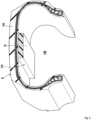
- FIG. 1 is a tire meridian cross-sectional view of a pneumatic tire (hereinafter, may be simply referred to as a "tire") 1, in a standardized state, according to an embodiment of the present invention.
- FIG. 1 shows a cross-section of the annularly extending tire 1 as taken along an imaginary plane that passes through the tire rotation axis and is orthogonal to the tire circumferential direction.
- the pneumatic tire 1 is for a passenger car.
- the present invention may be applied to, for example, the heavy duty pneumatic tire 1.
- the "standardized state” represents a state in which a tire is mounted on a standardized rim and is inflated to a standardized internal pressure and no load is applied to the tire, in a case where the tire is a pneumatic tire for which various standards are defined.
- the standardized state represents a standard use state, corresponding to a purpose of use of the tire, in which the tire is not mounted to a vehicle and no load is applied to the tire.
- dimensions and the like of components of the tire are represented as values measured in the standardized state.
- the "standardized rim” represents a rim that is defined by a standard, in a standard system including the standard on which the tire is based, for each tire, and is, for example, “standard rim” in the JATMA standard, "Design Rim” in the TRA standard, or “Measuring Rim” in the ETRTO standard.
- the "standardized internal pressure” represents an air pressure that is defined by a standard, in a standard system including the standard on which the tire is based, for each tire, and is “maximum air pressure” in the JATMA standard, the maximum value recited in the table "TIRE LOAD LIMITS AT VARIOUS COLD INFLATION PRESSURES" in the TRA standard, or "INFLATION PRESSURE” in the ETRTO standard.
- the tire 1 according to the present invention is mounted to a vehicle that is equipped with a puncture repair kit including a puncture sealant.
- the puncture repair kit allows puncture repair to be performed by injecting the puncture sealant through an air valve of a punctured tire.
- the puncture sealant injected into the tire is cured as the sealant passes through a puncture hole and can close the puncture hole.
- puncture repair can be performed by injecting the puncture sealant into the tire through the air valve as described above, and therefore, in the tire 1 according to the present invention, a tread portion 2 has such a stiffness that the closed puncture hole is not opened even by running with the tire after the puncture repair.
- the tread portion 2 includes at least a carcass 6 and a belt layer 7 described below.
- the carcass 6 extends from one of bead portions 4 to the other of the bead portions 4 through one of sidewall portions 3, the tread portion 2, and the other of the sidewall portions 3.
- the carcass 6 has at least one carcass ply 6A and has two carcass plies 6A in the present embodiment.
- an array of carcass cords is covered with topping rubber.
- the carcass cords are, for example, arranged at an angle of 75 to 90° with respect to the tire circumferential direction.
- organic fibers such as polyester fibers, nylon fibers, rayon fibers, polyethylene naphthalate fibers, or aramid fibers are used.
- the carcass ply 6A includes, for example, a body portion 6a and turned-up portions 6b.
- the body portion extends from the tread portion 2 to bead cores 5 through the sidewall portions 3.
- the turned-up portions 6b are continuous with the body portion 6a, and are each turned up around the bead core 5 from the inner side to the outer side in the tire axial direction and extend outward in the tire radial direction.
- the belt layer 7 is disposed outward of the carcass 6 in the tire radial direction in the tread portion 2.
- the belt layer 7 includes at least one belt ply.
- the belt layer 7 includes two belt plies 7A and 7B.
- the belt plies 7A and 7B are each formed of an array of belt cords covered with topping rubber.
- the tire 1 includes a pneumatic tire body 1A that defines a tire inner cavity 1B, and a porous noise damper 10 that is disposed in the tire inner cavity 1B.
- the noise damper 10 is capable of absorbing vibrations of air in the tire 1 during running with the tire 1, and contributes to reduction of noise generated by the tire.
- the noise damper 10 according to the present invention is not fixed to the pneumatic tire body 1A in the tire inner cavity 1B, and can be freely removed from the pneumatic tire body 1A. Therefore, in the tire 1 according to the present invention, after puncture repair is performed by injecting the puncture sealant into the tire, the noise damper 10 that has absorbed a part of the puncture sealant can be easily removed from the pneumatic tire body 1A, and therefore, the tire can be continuously used with vibrations reduced during running.
- the dimensions of the noise damper 10 described below are measured in a state where the tire 1 is not mounted on a rim, a distance between the pair of the bead cores 5 is set so as to correspond to the above-described standardized state, and the noise damper 10 is disposed in the tire inner cavity 1B, unless otherwise specified.
- the noise damper 10 is, for example, formed of a porous sponge material.
- the sponge material is, for example, foam of rubber or synthetic resin, and is open-cell foamed.
- polyurethane sponge having both an ether bond and an ester bond is used.
- the present invention is not limited thereto.
- the noise damper 10 has an air permeability in a specific range, the noise damper 10 retains the absorbed puncture sealant as it is, so that the puncture sealant is unlikely to reach a puncture hole.
- the air permeability of the noise damper 10 is preferably 27 ml/cm 2 /s or less. Thus, the above-described failure can be inhibited.
- the air permeability is measured in accordance with JIS K6400-7.
- the noise damper 10 has a high air permeability, if the noise damper 10 absorbs a puncture sealant, the absorbed puncture sealant is easily discharged again, and therefore, the above-described failure can be inhibited.
- the air permeability of the noise damper 10 may be, for example, 62 ml/cm 2 /s or more.
- FIG. 2 is an enlarged perspective view of the pneumatic tire body 1A and the noise damper 10 in FIG. 1 .
- the noise damper 10 is in contact with a surface of the tread portion 2 on the tire inner cavity 1B side (the noise damper 10 is not fixed to the surface).
- a cross-section of the noise damper 10 orthogonal to the tire circumferential direction is rectangular.
- the cross-section of the noise damper 10 has a rectangular shape laterally elongated in the tire axial direction.
- the noise damper 10 is in contact with almost the entirety (80% or more) of the tire inner cavity 1B in the tire circumferential direction.
- the noise damper 10 thus configured can exhibit excellent noise damping effect and durability.
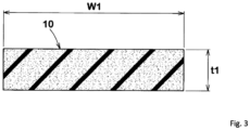
- FIG. 3 is an enlarged cross-sectional view of the noise damper 10.
- the greatest thickness t1 of the noise damper 10 in the tire radial direction is 10 to 40 mm.
- the greatest width W1 of the noise damper 10 in the tire axial direction is 20 to 80% and preferably 20 to 40% of a cross-sectional width Wt (see FIG. 1 ) of the pneumatic tire body 1A.
- the noise damper 10 thus configured is unlikely to be separated from the pneumatic tire body 1A during running with the tire. Therefore, the wear of the noise damper 10 is inhibited.
- FIG. 4 is a conceptual diagram illustrating a side surface of the tire 1.
- the noise damper 10 is indicated by a dashed line.
- the noise damper 10 of the present embodiment has an annular structure including a first end 10a in the tire circumferential direction, a second end 10b in the tire circumferential direction, and an adhering portion 13 that adheres the first end 10a and the second end 10b to each other.
- the adhering portion 13 is indicated by dots.
- the end portions of the noise damper 10 can be inhibited from coming into contact with the rim or the like and being worn, thereby exhibiting excellent durability.
- the first end 10a and the second end 10b are, for example, adhered to each other with an adhesive agent.
- the first end 10a and the second end 10b may be welded to each other (the sponge material is melted by heat to adhere the first end 10a and the second end 10b).
- the annular noise damper 10 is slightly compressed and disposed in the tire inner cavity 1B, and therefore, is not locally lifted from the pneumatic tire body 1A, and 90% or more, preferably, the entirety, of an outer side surface 10s of the noise damper 10 in the tire radial direction is in contact with the pneumatic tire body 1A.
- the noise damper 10 thus configured is allowed to rotate together with the tire 1 although the noise damper 10 is not fixed to the pneumatic tire body 1A. Therefore, the noise damper 10 is unlikely to be worn and durability is improved.
- the greatest length of the noise damper 10 from the first end 10a to the second end 10b is preferably 94 to 107% of the greatest circumferential length of the tire inner cavity 1B (see FIG. 1 ).
- the greatest circumferential length of the tire inner cavity 1B refers to the greatest length, in the tire circumferential direction, of the inner surface of the pneumatic tire body 1A.
- the length of the circumference of a circle formed by the inner surface of the pneumatic tire body 1A and the tire equator plane intersecting each other corresponds to the greatest circumferential length.
- FIG. 5 is a diagram illustrating a side surface of a tire 1 of another embodiment.
- the noise damper 10 of the present embodiment has a non-annular structure that has a first end 10a in the tire circumferential direction, and a second end 10b, in the tire circumferential direction, which is not adhered to the first end 10a.
- the noise damper 10 thus configured contributes to easy replacement after use of the puncture sealant.
- the greatest length of the noise damper 10 from the first end 10a to the second end 10b is preferably 85 to 99% of the greatest circumferential length of the tire inner cavity 1B.
- the noise damper 10 can exhibit a sufficient noise damping effect and can be easily replaced.
- FIG. 6 is an enlarged cross-sectional view of a noise damper 10 of still another embodiment.
- the noise damper 10 of the present embodiment at least one groove 15 is formed in the outer side surface 10s (surface on the tire inner cavity 1B side) in the tire radial direction.
- a plurality of the grooves 15 extending continuously in the tire circumferential direction are formed in the tire axial direction.
- An opening width W2 of the groove 15 is 3 to 10% of the greatest width W1 of the noise damper 10 in the tire axial direction.
- a depth d1 of the groove 15 is, for example, 15 to 20% of the greatest thickness t1 of the noise damper 10.
- the groove 15 thus configured allows a puncture sealant to easily reach a puncture hole during puncture repair.
- the groove 15 is not limited to the above-described configuration.
- the groove 15 may extend in the tire axial direction (not illustrated).
- the groove 15 thus configured allows a puncture sealant to easily move also in the tire axial direction, and the above-described effect can be further enhanced.
- a second aspect of the present invention is a puncture repair method for the above-described pneumatic tire 1.
- FIG. 7 is a conceptual diagram of a puncture repair kit 20 used in the present invention.
- the puncture repair kit 20 is expressed at a larger scale than an actual scale as compared with the tire 1.
- the puncture repair kit 20 includes a bottle unit 21 containing a puncture sealant, and a compressor 22 capable of supplying high-pressure air.
- the bottle unit 21 is preferably mounted to the compressor 22 in use.
- FIG. 8 is a flow chart showing the puncture repair method for the pneumatic tire according to the present invention. As shown in FIG. 8 , the puncture repair method includes at least a first step S1 and a second step S2 described below.
- the puncture repair kit 20 in FIG. 7 a puncture sealant is injected into the tire inner cavity, and a puncture hole is filled with the puncture sealant. Thereafter, the air pressure of the tire is adjusted as appropriate, so that running with the tire can be performed as usual.
- the noise damper that has absorbed a part of the puncture sealant filled in the tire inner cavity 1B is removed from the pneumatic tire body 1A.
- the noise damper 10 is not fixed in the tire inner cavity 1B, and therefore, this operation can be easily carried out. Therefore, the tire can be continuously used after the puncture repair.
- the puncture repair method according to the present invention preferably further includes a third step S3 of disposing, in the tire inner cavity, a new noise damper that has not absorbed a puncture sealant, after the second step S2.
- a third step S3 of disposing, in the tire inner cavity, a new noise damper that has not absorbed a puncture sealant, after the second step S2.
- the present invention is not limited thereto.
- the tire after the second step S2, the tire may be used without disposing a new noise damper 10 in the pneumatic tire body 1A.
- the puncture repair method according to the present invention may also include a step of removing the puncture sealant remaining in the tire inner cavity 1B.
- FIG. 9 is a conceptual diagram of a vehicle 25 to which the pneumatic tire 1 according to the present invention is mounted.
- This vehicle has the tire 1 (see FIG. 1 ) mounted thereto and is equipped with the puncture repair kit 20 (see FIG. 7 ). Therefore, the vehicle 25 can continue to use the tire even after puncture repair.
- the vehicle 25 is not equipped with a spare tire, and, instead thereof, has the tire 1 mounted thereto and is equipped with the puncture repair kit 20.
- a vehicle that is not equipped with a spare tire can be expected to have improved fuel economy performance, and can assure a wide vehicle interior space.
- the present invention includes the following aspects.
- a pneumatic tire which is to be mounted to a vehicle equipped with a puncture repair kit including a puncture sealant, and for which puncture repair is performed by injecting the puncture sealant into the tire, the pneumatic tire including:
- the pneumatic tire according to Present Invention 1 in which the noise damper has an annular structure including a first end in a tire circumferential direction, a second end in the tire circumferential direction, and an adhering portion for adhering the first end and the second end to each other.
- the pneumatic tire according to Present Invention 1 in which the noise damper has a non-annular structure having a first end in a tire circumferential direction, and a second end, in the tire circumferential direction, which is not adhered to the first end.
- a greatest width of the noise damper in a tire axial direction is 20 to 80% of a cross-sectional width of the pneumatic tire body.
- the puncture repair method for a pneumatic tire according to Present Invention 11 further including a third step of disposing, in the tire inner cavity, a new noise damper that has not absorbed the puncture sealant, after the second step.
- a vehicle including:
Landscapes
- Engineering & Computer Science (AREA)
- Mechanical Engineering (AREA)
- Tires In General (AREA)
Abstract
Description
- The present invention relates to a pneumatic tire, a puncture repair method for the pneumatic tire, and a vehicle.
-
Japanese Laid-Open Patent Publication No. 2022-069984 - In recent years, puncture repair kits which allow, when a pneumatic tire is punctured, a hole in the tire to be closed by injecting a puncture sealant into the tire inner cavity have become widespread. Vehicles are increasingly equipped with such puncture repair kits instead of spare tires.
- When a pneumatic tire having the porous noise damper is repaired by using the above-described puncture repair kit, a part of the puncture sealant is absorbed also by the noise damper, so that the weight of the noise damper is locally increased. Such a weight imbalance of the noise damper increases vibrations during running with the tire, and therefore, the tire needs to be replaced after the puncture repair.
- The present invention has been made in view of the aforementioned circumstances. A main object of the present invention is to provide a pneumatic tire that can be continuously used with vibrations and the like reduced during running even after puncture repair is performed by injecting a puncture sealant, and the like.
- The present invention is directed to a pneumatic tire which is to be mounted to a vehicle equipped with a puncture repair kit including a puncture sealant, and for which puncture repair is performed by injecting the puncture sealant into the tire. The pneumatic tire includes: a pneumatic tire body defining a tire inner cavity; and a porous noise damper disposed in the tire inner cavity. The noise damper is not fixed to the pneumatic tire body in the tire inner cavity, and is configured to be freely removable from the pneumatic tire body.
- The pneumatic tire according to the present invention has the above-described configuration, and can thus be continuously used with vibrations and the like reduced during running by easily removing the noise damper from the pneumatic tire body, even after puncture repair is performed by injecting the puncture sealant.
-
-
FIG. 1 is a tire meridian cross-sectional view of a pneumatic tire according to an embodiment of the present invention; -
FIG. 2 is an enlarged perspective view of a pneumatic tire body and a noise damper inFIG. 1 ; -
FIG. 3 is an enlarged cross-sectional view of the noise damper inFIG. 1 ; -
FIG. 4 is a conceptual diagram illustrating a side surface of the tire inFIG. 1 ; -
FIG. 5 is a conceptual diagram illustrating a side surface of a tire of another embodiment; -
FIG. 6 is an enlarged cross-sectional view of a noise damper of still another embodiment; -
FIG. 7 is a conceptual diagram of a puncture repair kit used in the present invention; -
FIG. 8 is a flow chart showing a puncture repair method for the pneumatic tire according to the present invention; and -
FIG. 9 is a conceptual diagram of a vehicle to which the pneumatic tire according to the present invention is mounted. - An embodiment of the present invention will be described below with reference to the accompanying drawings. Although the drawings represent features of the present invention, the drawings may include exaggerated representations and the dimensional ratios may be expressed so as to be different from those of the actual structure, for ease of understanding of the present invention. In addition, the same or common components are denoted by the same reference characters throughout embodiments, and will not be redundantly described.
-
FIG. 1 is a tire meridian cross-sectional view of a pneumatic tire (hereinafter, may be simply referred to as a "tire") 1, in a standardized state, according to an embodiment of the present invention.FIG. 1 shows a cross-section of the annularly extendingtire 1 as taken along an imaginary plane that passes through the tire rotation axis and is orthogonal to the tire circumferential direction. As shown inFIG. 1 , in the present embodiment, thepneumatic tire 1 is for a passenger car. However, the present invention may be applied to, for example, the heavy dutypneumatic tire 1. - The "standardized state" represents a state in which a tire is mounted on a standardized rim and is inflated to a standardized internal pressure and no load is applied to the tire, in a case where the tire is a pneumatic tire for which various standards are defined. For tires for which various standards are not defined, the standardized state represents a standard use state, corresponding to a purpose of use of the tire, in which the tire is not mounted to a vehicle and no load is applied to the tire. In the description herein, unless otherwise specified, dimensions and the like of components of the tire are represented as values measured in the standardized state.
- The "standardized rim" represents a rim that is defined by a standard, in a standard system including the standard on which the tire is based, for each tire, and is, for example, "standard rim" in the JATMA standard, "Design Rim" in the TRA standard, or "Measuring Rim" in the ETRTO standard.
- The "standardized internal pressure" represents an air pressure that is defined by a standard, in a standard system including the standard on which the tire is based, for each tire, and is "maximum air pressure" in the JATMA standard, the maximum value recited in the table "TIRE LOAD LIMITS AT VARIOUS COLD INFLATION PRESSURES" in the TRA standard, or "INFLATION PRESSURE" in the ETRTO standard.
- The
tire 1 according to the present invention is mounted to a vehicle that is equipped with a puncture repair kit including a puncture sealant. The puncture repair kit allows puncture repair to be performed by injecting the puncture sealant through an air valve of a punctured tire. The puncture sealant injected into the tire is cured as the sealant passes through a puncture hole and can close the puncture hole. In addition, in thetire 1 according to the present invention, puncture repair can be performed by injecting the puncture sealant into the tire through the air valve as described above, and therefore, in thetire 1 according to the present invention, atread portion 2 has such a stiffness that the closed puncture hole is not opened even by running with the tire after the puncture repair. Specifically, thetread portion 2 includes at least acarcass 6 and abelt layer 7 described below. - The
carcass 6 extends from one ofbead portions 4 to the other of thebead portions 4 through one ofsidewall portions 3, thetread portion 2, and the other of thesidewall portions 3. Thecarcass 6 has at least onecarcass ply 6A and has twocarcass plies 6A in the present embodiment. In thecarcass ply 6A, for example, an array of carcass cords is covered with topping rubber. The carcass cords are, for example, arranged at an angle of 75 to 90° with respect to the tire circumferential direction. For the carcass cords, for example, organic fibers such as polyester fibers, nylon fibers, rayon fibers, polyethylene naphthalate fibers, or aramid fibers are used. - The
carcass ply 6A includes, for example, abody portion 6a and turned-upportions 6b. The body portion extends from thetread portion 2 to beadcores 5 through thesidewall portions 3. The turned-upportions 6b are continuous with thebody portion 6a, and are each turned up around thebead core 5 from the inner side to the outer side in the tire axial direction and extend outward in the tire radial direction. - The
belt layer 7 is disposed outward of thecarcass 6 in the tire radial direction in thetread portion 2. Thebelt layer 7 includes at least one belt ply. In the present embodiment, thebelt layer 7 includes twobelt plies belt plies - In addition, the
tire 1 according to the present invention includes apneumatic tire body 1A that defines a tireinner cavity 1B, and aporous noise damper 10 that is disposed in the tireinner cavity 1B. Thenoise damper 10 is capable of absorbing vibrations of air in thetire 1 during running with thetire 1, and contributes to reduction of noise generated by the tire. - Conventionally, when a pneumatic tire having a porous noise damper is repaired by using the above-described puncture repair kit, a part of the puncture sealant is absorbed also by the noise damper, so that the weight of the noise damper is locally increased. Such a weight imbalance of the noise damper increases vibrations during running with the tire, and therefore, the tire needs to be replaced after the puncture repair.
- Meanwhile, the noise damper 10 according to the present invention is not fixed to the
pneumatic tire body 1A in the tireinner cavity 1B, and can be freely removed from thepneumatic tire body 1A. Therefore, in thetire 1 according to the present invention, after puncture repair is performed by injecting the puncture sealant into the tire, thenoise damper 10 that has absorbed a part of the puncture sealant can be easily removed from thepneumatic tire body 1A, and therefore, the tire can be continuously used with vibrations reduced during running. - The configurations of the present embodiment will be described below in more detail. The configurations described below represent a specific mode of the present embodiment. Therefore, it is needless to say that the present invention can exhibit the above-described effect even when the configurations described below are not provided. In addition, even when any one of the configurations described below is independently applied to the tire according to the present invention having the above-described characteristics, performance improvement corresponding to each configuration can be expected. Furthermore, when some of the configurations described below are applied in combination, complex performance improvement corresponding to the configurations can be expected.
- The dimensions of the
noise damper 10 described below are measured in a state where thetire 1 is not mounted on a rim, a distance between the pair of thebead cores 5 is set so as to correspond to the above-described standardized state, and thenoise damper 10 is disposed in the tireinner cavity 1B, unless otherwise specified. - The
noise damper 10 is, for example, formed of a porous sponge material. The sponge material is, for example, foam of rubber or synthetic resin, and is open-cell foamed. In a preferable embodiment, as thenoise damper 10, polyurethane sponge having both an ether bond and an ester bond is used. However, the present invention is not limited thereto. - If the
noise damper 10 has an air permeability in a specific range, thenoise damper 10 retains the absorbed puncture sealant as it is, so that the puncture sealant is unlikely to reach a puncture hole. From this viewpoint, for example, the air permeability of thenoise damper 10 is preferably 27 ml/cm2/s or less. Thus, the above-described failure can be inhibited. The air permeability is measured in accordance with JIS K6400-7. - In a case where the
noise damper 10 has a high air permeability, if thenoise damper 10 absorbs a puncture sealant, the absorbed puncture sealant is easily discharged again, and therefore, the above-described failure can be inhibited. From this viewpoint, the air permeability of thenoise damper 10 may be, for example, 62 ml/cm2/s or more. -
FIG. 2 is an enlarged perspective view of thepneumatic tire body 1A and thenoise damper 10 inFIG. 1 . As illustrated inFIG. 2 , thenoise damper 10 is in contact with a surface of thetread portion 2 on the tireinner cavity 1B side (thenoise damper 10 is not fixed to the surface). A cross-section of thenoise damper 10 orthogonal to the tire circumferential direction is rectangular. In a preferable embodiment, the cross-section of thenoise damper 10 has a rectangular shape laterally elongated in the tire axial direction. Thenoise damper 10 is in contact with almost the entirety (80% or more) of the tireinner cavity 1B in the tire circumferential direction. Thenoise damper 10 thus configured can exhibit excellent noise damping effect and durability. -
FIG. 3 is an enlarged cross-sectional view of thenoise damper 10. As illustrated inFIG. 3 , the greatest thickness t1 of thenoise damper 10 in the tire radial direction is 10 to 40 mm. In addition, the greatest width W1 of thenoise damper 10 in the tire axial direction is 20 to 80% and preferably 20 to 40% of a cross-sectional width Wt (seeFIG. 1 ) of thepneumatic tire body 1A. Thenoise damper 10 thus configured is unlikely to be separated from thepneumatic tire body 1A during running with the tire. Therefore, the wear of thenoise damper 10 is inhibited. -
FIG. 4 is a conceptual diagram illustrating a side surface of thetire 1. InFIG. 4 , thenoise damper 10 is indicated by a dashed line. As illustrated inFIG. 4 , thenoise damper 10 of the present embodiment has an annular structure including afirst end 10a in the tire circumferential direction, asecond end 10b in the tire circumferential direction, and an adheringportion 13 that adheres thefirst end 10a and thesecond end 10b to each other. InFIG. 4 , the adheringportion 13 is indicated by dots. In thenoise damper 10 thus configured, the end portions of thenoise damper 10 can be inhibited from coming into contact with the rim or the like and being worn, thereby exhibiting excellent durability. - The
first end 10a and thesecond end 10b are, for example, adhered to each other with an adhesive agent. In another embodiment, thefirst end 10a and thesecond end 10b may be welded to each other (the sponge material is melted by heat to adhere thefirst end 10a and thesecond end 10b). - In the present embodiment, the
annular noise damper 10 is slightly compressed and disposed in the tireinner cavity 1B, and therefore, is not locally lifted from thepneumatic tire body 1A, and 90% or more, preferably, the entirety, of anouter side surface 10s of thenoise damper 10 in the tire radial direction is in contact with thepneumatic tire body 1A. Thenoise damper 10 thus configured is allowed to rotate together with thetire 1 although thenoise damper 10 is not fixed to thepneumatic tire body 1A. Therefore, thenoise damper 10 is unlikely to be worn and durability is improved. - In order to achieve the above-described configuration, in a natural state in which the
first end 10a and thesecond end 10b of thenoise damper 10 are not adhered to each other, and thenoise damper 10 is linearly extended on a plane, the greatest length of thenoise damper 10 from thefirst end 10a to thesecond end 10b is preferably 94 to 107% of the greatest circumferential length of the tireinner cavity 1B (seeFIG. 1 ). The greatest circumferential length of the tireinner cavity 1B refers to the greatest length, in the tire circumferential direction, of the inner surface of thepneumatic tire body 1A. In the present embodiment in which thetread portion 2 is curved so as to protrude outward in the tire radial direction, the length of the circumference of a circle formed by the inner surface of thepneumatic tire body 1A and the tire equator plane intersecting each other corresponds to the greatest circumferential length. -
FIG. 5 is a diagram illustrating a side surface of atire 1 of another embodiment. As illustrated inFIG. 5 , thenoise damper 10 of the present embodiment has a non-annular structure that has afirst end 10a in the tire circumferential direction, and asecond end 10b, in the tire circumferential direction, which is not adhered to thefirst end 10a. Thenoise damper 10 thus configured contributes to easy replacement after use of the puncture sealant. - The greatest length of the
noise damper 10 from thefirst end 10a to thesecond end 10b is preferably 85 to 99% of the greatest circumferential length of the tireinner cavity 1B. Thus, thenoise damper 10 can exhibit a sufficient noise damping effect and can be easily replaced. -
FIG. 6 is an enlarged cross-sectional view of anoise damper 10 of still another embodiment. As illustrated inFIG. 6 , in thenoise damper 10 of the present embodiment, at least onegroove 15 is formed in theouter side surface 10s (surface on the tireinner cavity 1B side) in the tire radial direction. In a preferable embodiment, a plurality of thegrooves 15 extending continuously in the tire circumferential direction are formed in the tire axial direction. An opening width W2 of thegroove 15 is 3 to 10% of the greatest width W1 of thenoise damper 10 in the tire axial direction. A depth d1 of thegroove 15 is, for example, 15 to 20% of the greatest thickness t1 of thenoise damper 10. Thegroove 15 thus configured allows a puncture sealant to easily reach a puncture hole during puncture repair. - The
groove 15 is not limited to the above-described configuration. For example, thegroove 15 may extend in the tire axial direction (not illustrated). For example, thegroove 15 thus configured allows a puncture sealant to easily move also in the tire axial direction, and the above-described effect can be further enhanced. - A second aspect of the present invention is a puncture repair method for the above-described
pneumatic tire 1.FIG. 7 is a conceptual diagram of apuncture repair kit 20 used in the present invention. InFIG. 7 , thepuncture repair kit 20 is expressed at a larger scale than an actual scale as compared with thetire 1. Thepuncture repair kit 20 includes abottle unit 21 containing a puncture sealant, and acompressor 22 capable of supplying high-pressure air. Thebottle unit 21 is preferably mounted to thecompressor 22 in use. -
FIG. 8 is a flow chart showing the puncture repair method for the pneumatic tire according to the present invention. As shown inFIG. 8 , the puncture repair method includes at least a first step S1 and a second step S2 described below. - In the first step S1, as in conventional practice, for example, by using the
puncture repair kit 20 inFIG. 7 , a puncture sealant is injected into the tire inner cavity, and a puncture hole is filled with the puncture sealant. Thereafter, the air pressure of the tire is adjusted as appropriate, so that running with the tire can be performed as usual. - Conventionally, a part of the puncture sealant is absorbed also by the noise damper, so that vibrations of the tire increase during running after the first step S1. Therefore, the tire needs to be replaced even when no other portions of the tire have any failure.
- Meanwhile, in the second step S2 of the puncture repair method according to the present invention, the noise damper that has absorbed a part of the puncture sealant filled in the tire
inner cavity 1B is removed from thepneumatic tire body 1A. In the present invention, thenoise damper 10 is not fixed in the tireinner cavity 1B, and therefore, this operation can be easily carried out. Therefore, the tire can be continuously used after the puncture repair. - The puncture repair method according to the present invention preferably further includes a third step S3 of disposing, in the tire inner cavity, a new noise damper that has not absorbed a puncture sealant, after the second step S2. Thus, the noise damping effect is recovered, and thereafter, the tire can be continuously used.
- However, the present invention is not limited thereto. In another embodiment, after the second step S2, the tire may be used without disposing a
new noise damper 10 in thepneumatic tire body 1A. The puncture repair method according to the present invention may also include a step of removing the puncture sealant remaining in the tireinner cavity 1B. -
FIG. 9 is a conceptual diagram of avehicle 25 to which thepneumatic tire 1 according to the present invention is mounted. This vehicle has the tire 1 (seeFIG. 1 ) mounted thereto and is equipped with the puncture repair kit 20 (seeFIG. 7 ). Therefore, thevehicle 25 can continue to use the tire even after puncture repair. - The
vehicle 25 is not equipped with a spare tire, and, instead thereof, has thetire 1 mounted thereto and is equipped with thepuncture repair kit 20. A vehicle that is not equipped with a spare tire can be expected to have improved fuel economy performance, and can assure a wide vehicle interior space. - Although the pneumatic tire and the like according to the embodiments of the present invention have been described above in detail, the present invention is not limited to the above-described specific embodiments, and various modifications can be made to implement the present invention.
- The present invention includes the following aspects.
- A pneumatic tire which is to be mounted to a vehicle equipped with a puncture repair kit including a puncture sealant, and for which puncture repair is performed by injecting the puncture sealant into the tire, the pneumatic tire including:
- a pneumatic tire body defining a tire inner cavity; and
- a porous noise damper disposed in the tire inner cavity, in which
- the noise damper is not fixed to the pneumatic tire body in the tire inner cavity, and is configured to be freely removable from the pneumatic tire body.
- The pneumatic tire according to
Present Invention 1, in which the noise damper has an annular structure including a first end in a tire circumferential direction, a second end in the tire circumferential direction, and an adhering portion for adhering the first end and the second end to each other. - The pneumatic tire according to
Present Invention 2, in which a greatest length of the noise damper from the first end to the second end is 94 to 107% of a greatest circumferential length of the tire inner cavity, in a natural state in which the first end and the second end of the noise damper are not adhered to each other. - The pneumatic tire according to
Present Invention 1, in which the noise damper has a non-annular structure having a first end in a tire circumferential direction, and a second end, in the tire circumferential direction, which is not adhered to the first end. - The pneumatic tire according to
Present Invention 4, in which a greatest length of the noise damper from the first end to the second end is 85 to 99% of a greatest circumferential length of the tire inner cavity. - The pneumatic tire according to any one of
Present Inventions 1 to 5, in which - the pneumatic tire body includes a tread portion, and
- at least a part of the noise damper is in contact with a surface of the tread portion on the tire inner cavity side.
- The pneumatic tire according to any one of
Present Inventions 1 to 6, in which a greatest thickness of the noise damper in a tire radial direction is 10 to 40 mm. - The pneumatic tire according to any one of
Present Inventions 1 to 7, in which a greatest width of the noise damper in a tire axial direction is 20 to 80% of a cross-sectional width of the pneumatic tire body. - The pneumatic tire according to any one of
Present Inventions 1 to 8, in which a cross-section, of the noise damper, orthogonal to a tire circumferential direction is rectangular. - The pneumatic tire according to any one of
Present Inventions 1 to 9, in which the noise damper has at least one groove formed in an outer side surface in a tire radial direction. - A puncture repair method for a pneumatic tire, in which
- the pneumatic tire includes a pneumatic tire body defining a tire inner cavity, and a porous noise damper disposed in the tire inner cavity,
- the noise damper is not fixed to the pneumatic tire body in the tire inner cavity, and is configured to be freely removable from the pneumatic tire body, the puncture repair method including:
- a first step of injecting a puncture sealant into the tire inner cavity to fill a puncture hole with the puncture sealant; and
- a second step of removing, from the pneumatic tire body, the noise damper that has absorbed a part of the puncture sealant filled in the tire inner cavity.
- The puncture repair method for a pneumatic tire according to Present Invention 11, further including a third step of disposing, in the tire inner cavity, a new noise damper that has not absorbed the puncture sealant, after the second step.
- The puncture repair method for a pneumatic tire according to Present Invention 11, in which a new noise damper is not disposed in the pneumatic tire body after the second step.
- A vehicle including:
- a pneumatic tire mounted thereto; and
- a puncture repair kit for repairing a puncture of the pneumatic tire, in which
- the puncture repair kit is configured to inject a puncture sealant in a tire inner cavity when the pneumatic tire is punctured,
- the pneumatic tire includes a pneumatic tire body defining the tire inner cavity, and a porous noise damper disposed in the tire inner cavity, and
- the noise damper is not fixed to the pneumatic tire body in the tire inner cavity, and is configured to be freely removable from the pneumatic tire body.
- The vehicle according to Present Invention 14, in which the vehicle is not equipped with a spare tire.
Claims (15)
- A pneumatic tire (1) which is to be mounted to a vehicle (25) equipped with a puncture repair kit (20) including a puncture sealant, and for which puncture repair is performed by injecting the puncture sealant into the tire (1), the pneumatic tire (1) comprising:a pneumatic tire body (1A) defining a tire inner cavity (1B); anda porous noise damper (10) disposed in the tire inner cavity (1B), whereinthe noise damper (10) is not fixed to the pneumatic tire body (1A) in the tire inner cavity (1B), and is configured to be freely removable from the pneumatic tire body (1A).
- The pneumatic tire (1) according to claim 1, wherein the noise damper (10) has an annular structure including a first end (10a) in a tire circumferential direction, a second end (10b) in the tire circumferential direction, and an adhering portion (13) for adhering the first end (10a) and the second end (10b) to each other.
- The pneumatic tire (1) according to claim 2, wherein a greatest length of the noise damper (10) from the first end (10a) to the second end (10b) is 94 to 107% of a greatest circumferential length of the tire inner cavity (1B), in a natural state in which the first end (10a) and the second end (10b) of the noise damper (10) are not adhered to each other.
- The pneumatic tire (1) according to claim 1, wherein the noise damper (10) has a non-annular structure having a first end (10a) in a tire circumferential direction, and a second end (10b), in the tire circumferential direction, which is not adhered to the first end (10a).
- The pneumatic tire (1) according to claim 4, wherein a greatest length of the noise damper (10) from the first end (10a) to the second end (10b) is 85 to 99% of a greatest circumferential length of the tire inner cavity (1B).
- The pneumatic tire (1) according to any one of claims 1 to 5, whereinthe pneumatic tire body (1A) includes a tread portion (2), andat least a part of the noise damper (10) is in contact with a surface of the tread portion (2) on the tire inner cavity (1B) side.
- The pneumatic tire (1) according to any one of claims 1 to 6, wherein a greatest thickness (t1) of the noise damper (10) in a tire radial direction is 10 to 40 mm.
- The pneumatic tire (1) according to any one of claims 1 to 7, wherein a greatest width (W1) of the noise damper (10) in a tire axial direction is 20 to 80% of a cross-sectional width (Wt) of the pneumatic tire body (1A).
- The pneumatic tire (1) according to any one of claims 1 to 8, wherein a cross-section, of the noise damper (10), orthogonal to a tire circumferential direction is rectangular.
- The pneumatic tire (1) according to any one of claims 1 to 9, wherein the noise damper (10) has at least one groove (15) formed in an outer side surface (10s) in a tire radial direction.
- A puncture repair method for a pneumatic tire (1), whereinthe pneumatic tire (1) includes a pneumatic tire body (1A) defining a tire inner cavity (1B), and a porous noise damper (10) disposed in the tire inner cavity (1B),the noise damper (10) is not fixed to the pneumatic tire body (1A) in the tire inner cavity (1B), and is configured to be freely removable from the pneumatic tire body (1A), the puncture repair method comprising:a first step (S1) of injecting a puncture sealant into the tire inner cavity (1B) to fill a puncture hole with the puncture sealant; anda second step (S2) of removing, from the pneumatic tire body (1A), the noise damper (10) that has absorbed a part of the puncture sealant filled in the tire inner cavity (1B).
- The puncture repair method for a pneumatic tire (1) according to claim 11, further comprising a third step (S3) of disposing, in the tire inner cavity (1B), a new noise damper (10) that has not absorbed the puncture sealant, after the second step (S2).
- The puncture repair method for a pneumatic tire (1) according to claim 11, wherein a new noise damper (10) is not disposed in the pneumatic tire body (1A) after the second step (S2).
- A vehicle (25) comprising:a pneumatic tire (1) mounted thereto; anda puncture repair kit (20) for repairing a puncture of the pneumatic tire (1), whereinthe puncture repair kit (20) is configured to inject a puncture sealant in a tire inner cavity (1B) when the pneumatic tire (1) is punctured,the pneumatic tire (1) includes a pneumatic tire body (1A) defining the tire inner cavity (1B), and a porous noise damper (10) disposed in the tire inner cavity (1B), andthe noise damper (10) is not fixed to the pneumatic tire body (1A) in the tire inner cavity (1B), and is configured to be freely removable from the pneumatic tire body (1A).
- The vehicle (25) according to claim 14, wherein the vehicle (25) is not equipped with a spare tire.
Applications Claiming Priority (1)
| Application Number | Priority Date | Filing Date | Title |
|---|---|---|---|
| JP2023106276A JP2025005868A (en) | 2023-06-28 | 2023-06-28 | Pneumatic tire, method for repairing a punctured pneumatic tire, and vehicle |
Publications (1)
| Publication Number | Publication Date |
|---|---|
| EP4484142A1 true EP4484142A1 (en) | 2025-01-01 |
Family
ID=90468950
Family Applications (1)
| Application Number | Title | Priority Date | Filing Date |
|---|---|---|---|
| EP24165913.5A Pending EP4484142A1 (en) | 2023-06-28 | 2024-03-25 | Pneumatic tire, puncture repair method for pneumatic tire, and vehicle |
Country Status (3)
| Country | Link |
|---|---|
| EP (1) | EP4484142A1 (en) |
| JP (1) | JP2025005868A (en) |
| CN (1) | CN222004878U (en) |
Citations (11)
| Publication number | Priority date | Publication date | Assignee | Title |
|---|---|---|---|---|
| JP2002067608A (en) * | 2000-08-31 | 2002-03-08 | Sumitomo Rubber Ind Ltd | Assembly of pneumatic tire and rim |
| CN1954996A (en) * | 2005-10-24 | 2007-05-02 | 住友橡胶工业株式会社 | Method for manufacturing low noise pneumatic tire |
| US20090151837A1 (en) * | 2007-12-18 | 2009-06-18 | Gm Global Technology Operations, Inc. | Pneumatic tire and configuration for reducing a tire noise |
| EP2657008A1 (en) * | 2012-04-27 | 2013-10-30 | Wen-San Jhou | Vehicle-carried air compressor device |
| DE102013012827A1 (en) * | 2012-08-02 | 2014-02-06 | Toyo Tire & Rubber Co., Ltd. | Arrangement of pneumatic tire and rim |
| DE112014005334T5 (en) * | 2013-11-21 | 2016-08-04 | The Yokohama Rubber Co., Ltd. | tire |
| DE112006001015B4 (en) * | 2005-04-28 | 2019-05-09 | The Yokohama Rubber Co., Ltd. | Noise reduction device, manufacturing method for the noise reduction device and pneumatic tire having the noise reduction device |
| US20200023599A1 (en) * | 2017-02-08 | 2020-01-23 | The Yokohama Rubber Co., Ltd. | Pneumatic Tire and Method of Manufacturing the Same |
| US20210070114A1 (en) * | 2017-11-13 | 2021-03-11 | Bridgestone Corporation | Tire |
| US20220126635A1 (en) * | 2019-02-05 | 2022-04-28 | Bridgestone Europe NV/SA [BE/BE] | Tire comprising a sealant layer and a sound-absorbing element |
| JP2022069984A (en) | 2020-10-26 | 2022-05-12 | 住友ゴム工業株式会社 | Pneumatic tire |
-
2023
- 2023-06-28 JP JP2023106276A patent/JP2025005868A/en active Pending
-
2024
- 2024-03-25 EP EP24165913.5A patent/EP4484142A1/en active Pending
- 2024-04-19 CN CN202420818551.8U patent/CN222004878U/en active Active
Patent Citations (11)
| Publication number | Priority date | Publication date | Assignee | Title |
|---|---|---|---|---|
| JP2002067608A (en) * | 2000-08-31 | 2002-03-08 | Sumitomo Rubber Ind Ltd | Assembly of pneumatic tire and rim |
| DE112006001015B4 (en) * | 2005-04-28 | 2019-05-09 | The Yokohama Rubber Co., Ltd. | Noise reduction device, manufacturing method for the noise reduction device and pneumatic tire having the noise reduction device |
| CN1954996A (en) * | 2005-10-24 | 2007-05-02 | 住友橡胶工业株式会社 | Method for manufacturing low noise pneumatic tire |
| US20090151837A1 (en) * | 2007-12-18 | 2009-06-18 | Gm Global Technology Operations, Inc. | Pneumatic tire and configuration for reducing a tire noise |
| EP2657008A1 (en) * | 2012-04-27 | 2013-10-30 | Wen-San Jhou | Vehicle-carried air compressor device |
| DE102013012827A1 (en) * | 2012-08-02 | 2014-02-06 | Toyo Tire & Rubber Co., Ltd. | Arrangement of pneumatic tire and rim |
| DE112014005334T5 (en) * | 2013-11-21 | 2016-08-04 | The Yokohama Rubber Co., Ltd. | tire |
| US20200023599A1 (en) * | 2017-02-08 | 2020-01-23 | The Yokohama Rubber Co., Ltd. | Pneumatic Tire and Method of Manufacturing the Same |
| US20210070114A1 (en) * | 2017-11-13 | 2021-03-11 | Bridgestone Corporation | Tire |
| US20220126635A1 (en) * | 2019-02-05 | 2022-04-28 | Bridgestone Europe NV/SA [BE/BE] | Tire comprising a sealant layer and a sound-absorbing element |
| JP2022069984A (en) | 2020-10-26 | 2022-05-12 | 住友ゴム工業株式会社 | Pneumatic tire |
Also Published As
| Publication number | Publication date |
|---|---|
| JP2025005868A (en) | 2025-01-17 |
| CN222004878U (en) | 2024-11-15 |
Similar Documents
| Publication | Publication Date | Title |
|---|---|---|
| EP3431309A1 (en) | Pneumatic tire | |
| EP3581399B1 (en) | Pneumatic tire | |
| EP3572241B1 (en) | Pneumatic tire | |
| EP4056387A1 (en) | Pneumatic tire | |
| EP4484142A1 (en) | Pneumatic tire, puncture repair method for pneumatic tire, and vehicle | |
| JP2975438B2 (en) | Pneumatic tire | |
| EP4484143A1 (en) | Pneumatic tire, puncture repair method for pneumatic tire, and vehicle | |
| EP4484141A1 (en) | Pneumatic tire, puncture repair method for pneumatic tire, and vehicle | |
| JP7733445B2 (en) | pneumatic tires | |
| JP2022100772A (en) | tire | |
| JP2002172918A (en) | Safety pneumatic tire | |
| JP2000351307A (en) | Run flat tire | |
| JP2883542B2 (en) | Pneumatic tire and manufacturing method thereof | |
| KR20210091400A (en) | A pneumatic tire | |
| JP2004090807A (en) | Assembly of tire and rim | |
| US20180370297A1 (en) | Run flat tire and method for manufacturing same | |
| JP2025109097A (en) | Pneumatic tires and sound dampers | |
| JP2002067632A (en) | Safety pneumatic tire | |
| EP4512640A1 (en) | Pneumatic tire | |
| JP2004090808A (en) | Safety tire | |
| JP3952179B2 (en) | Tire wheel assembly | |
| EP4721996A1 (en) | Tire | |
| JP2002059719A (en) | Safety pneumatic tire | |
| EP4434775A1 (en) | Tire assembly | |
| JP2002059718A (en) | Safety pneumatic tire |
Legal Events
| Date | Code | Title | Description |
|---|---|---|---|
| PUAI | Public reference made under article 153(3) epc to a published international application that has entered the european phase |
Free format text: ORIGINAL CODE: 0009012 |
|
| STAA | Information on the status of an ep patent application or granted ep patent |
Free format text: STATUS: THE APPLICATION HAS BEEN PUBLISHED |
|
| AK | Designated contracting states |
Kind code of ref document: A1 Designated state(s): AL AT BE BG CH CY CZ DE DK EE ES FI FR GB GR HR HU IE IS IT LI LT LU LV MC ME MK MT NL NO PL PT RO RS SE SI SK SM TR |
|
| P01 | Opt-out of the competence of the unified patent court (upc) registered |
Free format text: CASE NUMBER: APP_12444/2025 Effective date: 20250313 |
|
| STAA | Information on the status of an ep patent application or granted ep patent |
Free format text: STATUS: REQUEST FOR EXAMINATION WAS MADE |
|
| 17P | Request for examination filed |
Effective date: 20250530 |