EP4484099A1 - Stapler - Google Patents
Stapler Download PDFInfo
- Publication number
- EP4484099A1 EP4484099A1 EP24185066.8A EP24185066A EP4484099A1 EP 4484099 A1 EP4484099 A1 EP 4484099A1 EP 24185066 A EP24185066 A EP 24185066A EP 4484099 A1 EP4484099 A1 EP 4484099A1
- Authority
- EP
- European Patent Office
- Prior art keywords
- unit
- sheet
- bending
- link
- clincher
- Prior art date
- Legal status (The legal status is an assumption and is not a legal conclusion. Google has not performed a legal analysis and makes no representation as to the accuracy of the status listed.)
- Granted
Links
Images



Classifications
-
- B—PERFORMING OPERATIONS; TRANSPORTING
- B27—WORKING OR PRESERVING WOOD OR SIMILAR MATERIAL; NAILING OR STAPLING MACHINES IN GENERAL
- B27F—DOVETAILED WORK; TENONS; SLOTTING MACHINES FOR WOOD OR SIMILAR MATERIAL; NAILING OR STAPLING MACHINES
- B27F7/00—Nailing or stapling; Nailed or stapled work
- B27F7/17—Stapling machines
- B27F7/19—Stapling machines with provision for bending the ends of the staples on to the work
-
- B—PERFORMING OPERATIONS; TRANSPORTING
- B25—HAND TOOLS; PORTABLE POWER-DRIVEN TOOLS; MANIPULATORS
- B25C—HAND-HELD NAILING OR STAPLING TOOLS; MANUALLY OPERATED PORTABLE STAPLING TOOLS
- B25C5/00—Manually operated portable stapling tools; Hand-held power-operated stapling tools; Staple feeding devices therefor
- B25C5/10—Driving means
- B25C5/15—Driving means operated by electric power
-
- B—PERFORMING OPERATIONS; TRANSPORTING
- B25—HAND TOOLS; PORTABLE POWER-DRIVEN TOOLS; MANIPULATORS
- B25C—HAND-HELD NAILING OR STAPLING TOOLS; MANUALLY OPERATED PORTABLE STAPLING TOOLS
- B25C7/00—Accessories for nailing or stapling tools, e.g. supports
-
- B—PERFORMING OPERATIONS; TRANSPORTING
- B27—WORKING OR PRESERVING WOOD OR SIMILAR MATERIAL; NAILING OR STAPLING MACHINES IN GENERAL
- B27F—DOVETAILED WORK; TENONS; SLOTTING MACHINES FOR WOOD OR SIMILAR MATERIAL; NAILING OR STAPLING MACHINES
- B27F7/00—Nailing or stapling; Nailed or stapled work
- B27F7/17—Stapling machines
- B27F7/30—Driving means
Definitions
- the present disclosure relates to a stapler configured to bind a bundle of sheets with a staple.
- a fixing clincher having a guide groove for bending and guiding a pair of staple legs inward is disposed on a back surface side of a binding sheet, and the staple legs that are driven from a front surface side of the binding sheet toward the binding sheet by an operating unit and protrude to a binding sheet lower surface side of the staple legs are engaged with the guide groove, so that the staple legs are bent and guided inward.
- a height of a loop shape formed at base portions of the staple legs is larger than a thickness of the binding sheet, and a staple bound part has a large thickness.
- an electric stapler including a movable clincher that is configured to engage with staple legs protruding to a lower surface side of a binding sheet through the binding sheet and bend the staple legs from a base portion side (for example, see JP3526682B ).
- an electric stapler vertically and separately provided with a driver unit including a driver that drives a staple, a clincher unit including a clincher configured to bend the driven staple, and a motor provided in each of the driver unit and the clincher unit (for example, see JP5310381B ).
- a flat clinch is desirable so that staple legs would not protrude from a fold of a spread page of the booklet.
- the staple legs are generally bent from bases using a movable clincher.
- a stapler using a movable clincher requires not only a motor for operating a driver but also a motor for operating the movable clincher.
- a general electric stapler for square binding instead of saddle binding has a small sheet passing area, and thus a clincher and a driver can be disposed close to each other. For this reason, as described in JP3526682B , a structure that operates the driver and the clincher with one single motor can be relatively easily implemented.
- a saddle binding stapler requires a driver and a clincher separately from each other to ensure a large sheet passing area, making it structurally difficult to operate both the driver and the clincher with one single motor. Accordingly, a saddle binding stapler in the related art is separately provided with a motor for a driver and a motor for a clincher as described in JP5310381B .
- illustrative aspects of the present disclosure provide a stapler that can operate both a driver and a clincher with one single motor even in a saddle binding stapler (that is, it can implement flat clinch) and can accordingly mitigate an increase in a size of the stapler, the number of components, and the associated costs.
- a stapler for performing binding processing of binding a sheet with a staple
- the stapler including: a driver unit provided in a position orthogonal to a sheet surface of the sheet in a case of performing the binding processing, the driver unit being configured to drive the staple to the sheet; a bending unit provided in a position facing the driver unit through the sheet in the case of performing the binding processing, the bending unit being configured to bend a staple leg of the staple that is driven by the driver unit and penetrates the sheet; a single motor configured to operate the driver unit and the bending unit; a coupling portion coupling the driver unit and the bending unit on one side in a direction orthogonal to a sheet passing direction of the sheet passing between the driver unit and the bending unit and along the sheet surface in the case of performing the binding processing; and a transmission unit configured to transmit a driving force of the motor to the driver unit and/or the bending unit via the coupling portion.
- an upstream side and a downstream side in a sheet passing direction of a sheet are opened between a driver unit and a bending unit, and the sheet can pass therethrough.
- a driver unit and a bending unit of a stapler can be operated by a single motor and a position of a fold of a booklet can be bound with a staple, and thus costs can be reduced.
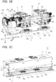
- FIG. 1A is a front view illustrating an example of a stapler according to the present illustrative embodiment
- FIG. 1B is a perspective view illustrating a main portion of the example of the stapler according to the present illustrative embodiment
- FIG. 1C is an external perspective view illustrating the example of the stapler according to the present illustrative embodiment
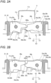
- FIGS. 2A and 2B are front sectional views illustrating a main portion of an example of a bending unit of the stapler according to the present illustrative embodiment
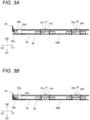
- FIGS. 3A and 3B are front sectional views illustrating the example of the bending unit of the stapler according to the present illustrative embodiment
- FIG. 4 is a perspective view illustrating a main portion of an example of an operating unit of the stapler according to the present illustrative embodiment.
- a stapler 1A includes a driver unit 2, a bending unit 3, a coupling portion 100, transmission units 101, 102, and 103, and an operating unit 5.
- the driver unit 2 is provided in a position orthogonal to a sheet surface of a sheet P during binding processing of binding the sheet P with a staple 11, and is configured to drive the staple 11 to the sheet P.
- the bending unit 3 is provided in a position facing the driver unit 2 through the sheet P during the above-described binding processing, and is configured to bend a pair of staple legs 11a and 11b of the staple 11 that is driven by the driver unit 2 and penetrates the sheet P.
- the coupling portion 100 couples the driver unit 2 and the bending unit 3 on one side in a direction orthogonal to a sheet passing direction of the sheet P passing between the driver unit 2 and the bending unit 3 and along the sheet surface of the sheet P before and after the above-described binding processing.
- the sheet passing direction of the sheet P is indicated by an arrow F.
- An arrow C indicates the direction along the sheet surface of the sheet P.
- the operating unit 5 includes a single motor 51.
- the single motor 51 is configured to operate the driver unit 2 and the bending unit 3.
- the transmission unit 101 is configured to transmit a driving force of the motor 51 to the driver unit 2.
- the transmission unit 102 is configured to transmit the driving force of the motor 51 to the coupling portion 100.
- the transmission unit 103 is configured to transmit the driving force of the motor 51 to the bending unit 3 via the coupling portion 100.
- the coupling portion 100 and the transmission units 101, 102, and 103 will be described in detail later.
- the driver unit 2 and the bending unit 3 face each other across a sheet area 10.
- the stapler 1A includes a frame 10a, a frame 10b, and a pair of frames 10c and 10d connecting the frame 10a and the frame 10b.
- the sheet area 10 is formed by a space between the driver unit 2 and the bending unit 3.
- the space between the driver unit 2 and the bending unit 3 is defined by the frame 10a, the frame 10b, and the pair of frames 10c and 10d connecting the frame 10a and the frame 10b.
- the frame 10a is provided with the driver unit 2 therein, which forms an exterior of the driver unit 2.
- the frame 10a is further provided with the motor 51 and the transmission units 101 and 102 therein.
- the frame 10b is provided with the bending unit 3 inside, which forms an exterior of the bending unit 3.
- the frame 10b further includes the transmission unit 103 therein.
- the frame 10c connects the frame 10a and the frame 10b on the one side in the direction orthogonal to the sheet passing direction of the sheet P indicated by the arrow F and along the sheet surface of the sheet P.
- the frame 10c is provided with the coupling portion 100 therein.
- the frame 10d connects the frame 10a and the frame 10b on the other side in the direction orthogonal to the sheet passing direction of the sheet P and along the sheet surface of the sheet P.
- the driver unit 2 does not protrude from the frame 10a to an inside of the sheet area 10 except when the sheet P is clamped between the driver unit 2 and the bending unit 3.
- the motor 51 and the transmission units 101 and 102 do not protrude from the frame 10a to the inside of the sheet area 10.
- the bending unit 3 and the transmission unit 103 do not protrude from the frame 10b to the inside of the sheet area 10.
- the coupling portion 100 does not protrude from the frame 10c to the inside of the sheet area 10.
- the sheet area 10 is open upstream and downstream of the sheet passing direction of the sheet P, allowing the sheet P to pass therethrough.
- Two sides of the sheet area 10 in the direction orthogonal to the sheet passing direction of the sheet P and along the sheet surface of the sheet P are blocked by the frames 10c and 10d.
- the frame 10c and the frame 10d face each other at an interval larger than a maximum width of the sheet P that can pass therethrough.
- the frame 10a and the frame 10b face each other at an interval larger than a thickness of a stack of a maximum number of sheets P that can be bound.
- the driver unit 2 and the bending unit 3 are coupled to each other via the frames 10c and 10d on two sides in the direction orthogonal to the sheet passing direction of the sheet P and along the sheet surface of the sheet P.
- the driver unit 2 includes a first driver unit 21, a second driver unit 22, and a power transmission unit 23.
- the first driver unit 21 is an example of a driver unit or a first driver unit.
- the staple 11 driven by the first driver unit 21 is an example of a first staple
- the pair of staple legs 11a and 11b of the staple 11 driven by the first driver unit 21 are examples of staple legs of the first staple.
- the second driver unit 22 is an example of a second driver unit.
- the staple 11 driven by the second driver unit 22 is an example of a second staple.
- the pair of staple legs 11a and 11b of the staple 11 driven by the second driver unit 22 are examples of staple legs of the second staple.
- the first driver unit 21 includes a driver plate 21a and a power transmission unit 21b.
- the driver plate 21a is supported in a manner of being movable along an extending direction of the pair of staple legs 11a and 11b of the staple 11.
- the power transmission unit 21b includes, for example, a gear that makes up a cam and a link that is displaceable by rotation of the gear.
- the power transmission unit 21b is configured to transmit movement of the operating unit 5 to the driver plate 21a.
- the driver plate 21a is configured to be operated by the operating unit 5 via the power transmission unit 21b and to drive the staple 11.
- the first driver unit 21 includes a forming plate for shaping the staple 11.
- the first driver unit 21 further includes an attachment portion to which a cartridge accommodating the staple 11 before shaping is removably mounted.
- the second driver unit 22 includes a driver plate 22a and a power transmission unit 22b.
- the driver plate 22a is supported in a manner of being movable along the extending direction of the pair of staple legs 11a and 11b of the staple 11.
- the power transmission unit 22b includes, for example, a gear that makes up a cam and a link that is displaceable by rotation of the gear.
- the power transmission unit 22b is configured to transmit the movement of the operating unit 5 to the driver plate 22a.
- the driver plate 22a is configured to be operated by the operating unit 5 via the power transmission unit 22b and to drive the staple 11.
- the second driver unit 22 includes a forming plate for shaping the staple 11.
- the second driver unit 22 further includes an attachment portion to which a cartridge accommodating the staple 11 before shaping is removably mounted.
- the power transmission unit 23 is configured by, for example, a shaft connecting the power transmission unit 21b of the first driver unit 21 and the power transmission unit 22b of the second driver unit 22, etc.
- the power transmission unit 23 is configured to transmit the movement transmitted from the operating unit 5 to the power transmission unit 21b to the power transmission unit 22b. Accordingly, the driver plate 21a and the driver plate 22a interlock.
- the first driver unit 21 and the second driver unit 22 are arranged side by side in the direction orthogonal to the sheet passing direction of the sheet P and along the sheet surface of the sheet P.
- a staple crown 11c of the staple 11 driven by the first driver unit 21 and the second driver unit 22 extends in the direction orthogonal to the sheet passing direction of the sheet P and along the sheet surface of the sheet P.
- the bending unit 3 includes a first bending unit 31 and a second bending unit 32.
- the first bending unit 31 is an example of a bending unit or a first bending unit.
- the second bending unit 32 is an example of a second bending unit.
- the first bending unit 31 includes a first clincher 31a, a second clincher 31b, and a clamping portion 33a.
- the first bending unit 31 faces the first driver unit 21 with the sheet area 10 interposed therebetween.
- the clamping portion 33a is a surface facing the first driver unit 21.
- the clamping portion 33a is provided on a frame 34a of the first bending unit 31.
- the clamping portion 33a has an opening 35a through which the first clincher 31a and the second clincher 31b are exposed.
- the first clincher 31a includes a receiving portion 36a and an acted portion 37a.
- the first clincher 31a is supported by the frame 34a in a manner of being rotatable about a shaft 38a as a fulcrum.
- the first clincher 31a abuts against the staple leg 11a during the above-described binding processing, and pivots in a bending direction of the staple leg 11a about the shaft 38a as the fulcrum.
- the rotation is also referred to as pivoting.
- the pivoting refers to rotation in a range of less than 360°.
- the first clincher 31a is movable between a bending standby position illustrated in FIG. 2A and a bending position illustrated in FIG. 2B by being rotatable about the shaft 38a as the fulcrum.
- the receiving portion 36a is provided at a portion that moves in directions toward and away from the clamping portion 33a by the rotation of the first clincher 31a about the shaft 38a as the fulcrum.
- the receiving portion 36a is exposed to the opening 35a of the clamping portion 33a.
- the receiving portion 36a is inclined in the direction away from the clamping portion 33a as approaching a tip end side facing the second clincher 31b from the shaft 38a.
- the receiving portion 36a moves in a first direction indicated by an arrow A1, which is the direction toward the clamping portion 33a from the bending standby position, by the rotation of the first clincher 31a with the shaft 38a as the fulcrum.
- the receiving portion 36a moves from the bending position in a second direction indicated by an arrow A2 opposite to the arrow A1, which is the direction away from the clamping portion 33a.
- the first clincher 31a has a tip end 300a.
- the acted portion 37a is provided at a portion opposite to the receiving portion 36a between the tip end 300a and the shaft 38a.
- the first clincher 31a moves from the bending standby position to the bending position by receiving a force for pressing the acted portion 37a.
- the second clincher 31b includes a receiving portion 36b and an acted portion 37b.
- the second clincher 31b is provided on a side of the clamping portion 33a that is opposite to a side facing the first driver unit 21.
- the second clincher 31b is supported by the frame 34a in a manner of being rotatable about a shaft 38b as a fulcrum.
- the second clincher 31b abuts against the staple leg 11b during the above-described binding processing, and pivots in a bending direction of the staple leg 11b about the shaft 38b as the fulcrum.
- the second clincher 31b is movable between the bending standby position illustrated in FIG. 2A and the bending position illustrated in FIG. 2B by being rotatable about the shaft 38b as the fulcrum.
- the receiving portion 36b is provided at a portion that moves in directions toward and away from the clamping portion 33a by the rotation of the second clincher 31b with the shaft 38b as the fulcrum.
- the receiving portion 36b is exposed to the opening 35a of the clamping portion 33a.
- the receiving portion 36b is inclined in the direction away from the clamping portion 33a as approaching a tip end side facing the first clincher 31a from the shaft 38b.
- the receiving portion 36b moves in the first direction indicated by the arrow A1, which is the direction toward the clamping portion 33a from the bending standby position, by the rotation of the second clincher 31b with the shaft 38b as the fulcrum.
- the receiving portion 36b moves from the bending position in the second direction indicated by the arrow A2, which is the direction away from the clamping portion 33a.
- the second clincher 31b has a tip end 300b.
- the acted portion 37b is provided at a portion opposite to the receiving portion 36b between the tip end 300b and the shaft 38b.
- the second clincher 31b is moves from the bending standby position to the bending position by receiving a force for pressing the acted portion 37b.
- the first clincher 31a moves to the bending standby position
- the second clincher 3 1b interlocks and moves to the bending standby position.
- the first clincher 31a moves to the bending position
- the second clincher 31b interlocks and moves to the bending position.
- the shafts 38a and 38b are examples of a first shaft
- the tip ends 300a and 300b are examples of a first tip end.
- the second bending unit 32 includes a first clincher 32a, a second clincher 32b, and a clamping portion 33b.
- the first clincher 32a and the second clincher 32b of the second bending unit 32 are examples of a pair of second clinchers.
- the second bending unit 32 faces the second driver unit 22 with the sheet area 10 interposed therebetween.
- the clamping portion 33b is a surface facing the second driver unit 22.
- the clamping portion 33b is provided on a frame 34b of the second bending unit 32.
- the clamping portion 33b has an opening 35b through which the first clincher 32a and the second clincher 32b are exposed.
- the first clincher 32a and the second clincher 32b of the second bending unit 32 have the same configuration as the first clincher 31a and the second clincher 31b of the first bending unit 31.
- the operating unit 5 includes the single motor 51 described above.
- the coupling portion 100 includes a first link 54.
- the transmission unit 101 includes a gear group 51b that meshes with a gear 51a of the motor 51, and a shaft 51c that rotates together with the gear group 51b.
- the transmission unit 102 includes a gear 53 and a gear 52 that meshes with the gear 53.
- the gear 52 is attached to the shaft 51c. In this way, the transmission unit 101 and the transmission unit 102 may share a part of a gear, a shaft, and the like.
- the transmission unit 103 includes a second link 55, a third link 55B, and a conversion unit 55C.
- the motor 51 is provided inside the frame 10a on a side of the first driver unit 21 that is opposite to a side on which the second driver unit 22 is provided along a direction intersecting the surface of the sheet P passing through the sheet area 10.
- the transmission unit 101 is configured to transmit rotation of the motor 51 to the power transmission unit 21b of the first driver unit 21 via the gear group 51b, the shaft 51c, and the like.
- the transmission unit 102 is configured to transmit the rotation of the motor 51 to the first link 54 configuring the coupling portion 100 via the gear group 51b, the shaft 51c, the gear 52, and the gear 53.
- the transmission units 101, 102, and 103 are examples of a first transmission unit.
- the gear 53 is provided inside the frame 10a of the driver unit 2.
- the gear 53 is provided outside the motor 51 relative to the first driver unit 21.
- an output shaft of the motor 51 protrudes inward toward the first driver unit 21, and the gear 51a is provided on an inner side facing the first driver unit 21.
- the rotation of the motor 51 is transmitted via the transmission unit 102 including the shaft 51c, which extends outward of the motor 51 relative to the first driver unit 21, and the gear 53 rotates.
- the gear 53 includes a cam groove 53a that draws a trajectory whose distance from a rotation center changes.
- the cam groove 53a is an example of a cam.
- the cam groove 53a extends in a circumferential direction of the gear 53.
- the first link 54 is an example of a link and a first link.
- the first link 54 is provided inside the frame 10c on the one side in the direction orthogonal to the sheet passing direction of the sheet P indicated by the arrow F and along the sheet surface of the sheet P relative to the sheet area 10.
- the first link 54 does not protrude toward the sheet area 10 or interfere with sheet passage.
- the first link 54 extends along a direction in which the driver unit 2 and the bending unit 3 face each other.
- the first link 54 is supported in a manner of being movable in a third direction indicated by an arrow B1 and a fourth direction indicated by an arrow B2.
- the third direction is along the direction in which the driver unit 2 and the bending unit 3 face each other, and the fourth direction is in the opposite direction to the third direction.
- the third direction and the fourth direction are directions orthogonal to the sheet surface of the sheet P passing through the sheet area 10, and in this example, they are in an upper-lower direction (e.g., vertical direction).
- the first link 54 includes a first cam follower 54a and a second cam follower 54b.
- the first cam follower 54a is provided on a driver unit 2 side along the direction in which the first link 54 extends.
- the second cam follower 54b is an example of the conversion unit 55C, and is provided on a bending unit 3 side along the direction in which the first link 54 extends.
- the second link 55 is an example of a link and a second link.
- the second link 55 is provided inside the frame 10b of the bending unit 3.
- the third link 55B is an example of a second transmission unit, a link, and a third link.
- the third link 55B is provided inside the frame 10b of the bending unit 3.
- the third link 55B is provided on an extension line of the second link 55.
- the second link 55 and the third link 55B extend along a direction in which the first bending unit 31 and the second bending unit 32 are arranged side by side.
- the second link 55 and the third link 55B are supported in a manner of being movable in a fifth direction indicated by an arrow C1 and a sixth direction indicated by an arrow C2.
- the fifth direction is along the direction in which the first bending unit 31 and the second bending unit 32 are arranged side by side, and the sixth direction is in the opposite direction to the fifth direction.
- the fifth direction and the sixth direction are directions along the sheet surface of the sheet P passing through the sheet area 10, and in this example, they are in a horizontal direction.
- the second link 55 includes a cam groove 55a and acting portions 56a and 56b.
- the third link 55B includes acting portions 56c and 56d.
- the cam groove 55a is an example of the conversion unit 55C.
- the cam groove 55a extends obliquely relative to the moving direction of the first link 54 and the moving directions of the second link 55 and the third link 55B.
- the second cam follower 54b of the first link 54 is inserted into the cam groove 55a.
- the acting portion 56a is an example of a protrusion or a first protrusion.
- the acting portion 56a faces the acted portion 37a of the first clincher 31a of the first bending unit 31.
- the acting portion 56b is an example of a protrusion or a first protrusion.
- the acting portion 56b faces the acted portion 37b of the second clincher 31b of the first bending unit 31.
- the acting portion 56c is an example of a second protrusion.
- the acting portion 56c faces the acted portion 37a of the first clincher 32a of the second bending unit 32.
- the acting portion 56d is an example of a second protrusion.
- the acting portion 56d faces the acted portion 37b of the second clincher 32b of the second bending unit 32.
- FIG. 3A illustrates a state in which the first clincher 31a and the second clincher 31b of the first bending unit 31 and the first clincher 32a and the second clincher 32b of the second bending unit 32 are in the bending standby position as illustrated in FIG. 2A .
- the first link 54 moves in the third direction indicated by the arrow B1 from this state
- the second cam follower 54b of the first link 54 presses a lower surface of the inclined cam groove 55a of the second link 55. Accordingly, the second link 55 moves in the fifth direction indicated by the arrow C1.
- FIG. 3B illustrates a state in which the first clincher 31a and the second clincher 31b of the first bending unit 31 and the first clincher 32a and the second clincher 32b of the second bending unit 32 are in the bending positions as illustrated in FIG. 2B .
- the first link 54 moves in the fourth direction indicated by the arrow B2 from this state
- the second cam follower 54b of the first link 54 presses an upper surface of the inclined cam groove 55a of the second link 55. Accordingly, the second link 55 moves in the sixth direction indicated by the arrow C2.
- the first cam follower 54a follows the trajectory of the cam groove 53a, so that the first link 54 moves in the third direction or the fourth direction. From a usage form of the stapler 1A, the moving direction of the first link 54 is the upper-lower direction, and the moving direction of the second link 55 is the horizontal direction.
- rotation operation of the gear 53 is converted into a linear motion of the first link 54 in the upper-lower direction, which is orthogonal to the sheet surface of the sheet P passing through the sheet area 10, and the linear motion of the first link 54 in the upper-lower direction (which may be referred to as the vertical linear motion of the first link 54) is converted into a linear motion of the second link 55 in the horizontal direction, which is aligned with the sheet surface of the sheet P passing through the sheet area 10. That is, the vertical linear motion of the first link 54 is converted into a horizontal linear motion of the second link 55.
- the first link 54 is located outside the sheet area 10 where the sheet P is located during the binding processing on the one side in the direction orthogonal to the sheet passing direction of the sheet P passing between the driver unit 2 and the bending unit 3 and along the sheet surface of the sheet P before and after the binding processing.
- the first link 54 displaces in a direction orthogonal to the sheet surface of the sheet P, following the cam groove 53a of the gear 53 that is an example of a cam.
- the second link 55 is located below the sheet area 10.
- the second link 55 moves in a direction along the sheet surface of the sheet P and is configured to pivot the first clincher 31a and the second clincher 31b of the first bending unit 31.
- the third link 55B is located below the sheet area 10.
- the third link 55B moves in the direction along the sheet surface of the sheet P and is configured to pivot the first clincher 32a and the second clincher 32b of the second bending unit 32.
- the conversion unit 55C is located between the first link 54 and the second link 55.
- the conversion unit 55C is configured to convert the displacement of the first link 54 in the direction orthogonal to the sheet surface of the sheet P into the displacement of the second link 55 in the direction along the sheet surface of the sheet P.
- the bending unit 3 includes a support member 39.
- the support member 39 supports the second link 55 from below to prevent the second link 55 from bending.
- the sheet P is conveyed until a center of the sheet P orthogonal to the sheet passing direction of the sheet P passing through the sheet area 10 is aligned with a driveing position of the staple 11 by the first driver unit 21 and the second driver unit 22. In a case where this alignment is achieved, the conveying of the sheet P is stopped.
- the driver plate 21a of the first driver unit 21 moves in the first direction indicated by the arrow A1, which is the driveing direction.
- the driver plate 22a of the second driver unit 22 interlocks with the driver plate 21a and moves in the driveing direction.
- the driver plate 21a moves in the driveing direction, so that the staple crown 11c of the staple 11 is pressed and the staple legs 11a and 11b penetrate the sheet P.
- the staple leg 11a penetrating the sheet P comes into contact with the receiving portion 36a of the first clincher 31a of the first bending unit 31.
- the staple leg 11b penetrating the sheet P comes into contact with the receiving portion 36b of the second clincher 31b of the first bending unit 31.
- the staple leg 11a penetrating the sheet P is guided along the inclined receiving portion 36a and bent inward by the movement of the first clincher 31a to the bending standby position.
- the staple leg 11b penetrating the sheet P is guided along the inclined receiving portion 36b and bent inward by the movement of the second clincher 3 1b to the bending standby position.
- the gear 53 rotates.
- the driver plate 21a moves in the driveing direction until the staple crown 11c of the staple 11 comes into contact with a front surface of the sheet P
- the gear 53 moves the first link 54 in the third direction indicated by the arrow B1.
- the acting portion 56a presses the acted portion 37a of the first clincher 31a of the first bending unit 31. Accordingly, the first clincher 31a moves from the bending standby position to the bending position by receiving a force for pressing the acted portion 37a.
- the receiving portion 36a presses the staple leg 11a toward a back surface of the sheet P, and bends a tip end of the staple leg 11a toward the back surface of the sheet P.
- the acting portion 56b presses the acted portion 37b of the second clincher 31b of the first bending unit 31. Accordingly, the second clincher 31b moves from the bending standby position to the bending position by receiving a force for pressing the acted portion 37b.
- the receiving portion 36b presses the staple leg 11b toward the back surface of the sheet P, and bends a tip end of the staple leg 11b toward the back surface of the sheet P.
- the operation is described with the first driver unit 21 and the first bending unit 31 as an example, and operation of the second driver unit 22 and the second bending unit 32 is the same.
- the coupling portion 100 is provided with the first link 54 on the one side outside the sheet area 10 in the direction orthogonal to the sheet passing direction of the sheet P indicated by the arrow F and along the sheet surface of the sheet P. Accordingly, the sheet area 10 is open upstream and downstream of the sheet passing direction of the sheet P, allowing the sheet P to pass therethrough.
- the stapler 1A can align the driveing position of the staple 11 driven by the first driver unit 21 and the second driver unit 22 with the center of the sheet P orthogonal to the sheet passing direction of the sheet P. Accordingly, the stapler 1A can bind the sheet P in a form called saddle binding.
- the stapler 1A includes the motor 51 in the driver unit 2, and is configured to operate the first driver unit 21 and the second driver unit 22 and to transmit a driving force of the motor 51 to the bending unit 3 through the first link 54, so that the clinchers can be operated.
- the stapler 1A that can bind the sheet P in a form called saddle binding
- an amount by which the bent staple legs protrude on the back surface of the sheet can be reduced.
- the tip ends of the staple legs can be directed to the back surface of the sheet. Further, costs can be reduced since the driver unit 2 and the bending unit 3 can be operated by the single motor 51.
- the first link 54 moves (linearly moves) along the frame 10c. Accordingly, space required for the movement of the first link 54 does not spread in directions toward and away from the sheet area 10, and an increase in a size of the stapler can be suppressed.
- the gear 53 is provided in the driver unit 2. Accordingly, no space for the gear 53 is necessary between the frame 10c and the sheet area 10, and an increase in the size of the stapler can be suppressed.
- the second link 55 and the third link 55B move (linearly move) along the frame 10b. Accordingly, space required for the movement of the second link 55 and the third link 55B does not spread in directions toward and away from the sheet area 10, and an increase in the size of the stapler can be suppressed.
- the receiving portion 36a moves in the directions toward and away from the clamping portion 33a by the rotation of the first clincher 31a with the shaft 38a as the fulcrum.
- the receiving portion 36a is separated from the clamping portion 33a. Accordingly, increasing a length of the receiving portion 36a can increase a range in which the staple leg 11a can come into contact with the receiving portion 36a.
- the receiving portion 36a approaches the clamping portion 33a. Accordingly, the staple leg 11a can be pressed against the back surface of the sheet P even when the receiving portion 36a has an increased length.
- the receiving portion 36b moves in the directions toward and away from the clamping portion 33b by the rotation of the second clincher 31b about the shaft 38b as the fulcrum.
- the receiving portion 36b is separated from the clamping portion 33b. Accordingly, increasing a length of the receiving portion 36b can increase a range in which the staple leg 11b can come into contact with the receiving portion 36b.
- the receiving portion 36b approaches the clamping portion 33b. Accordingly, the staple leg 11b can be pressed against the back surface of the sheet P even when the receiving portion 36b has an increased length.
- FIGS. 5A and 5B are perspective views of main portions of a first modification of the stapler according to the present illustrative embodiment.
- a stapler 1B includes a sheet area, a driver unit, which are not illustrated, a bending unit 3B, and an operating unit 5B.
- the bending unit 3B includes the first clincher 31a, the second clincher 31b, and a first acted portion 37c.
- the first clincher 31a includes the receiving portion 36a and the second acted portion 37a.
- the first clincher 31a is rotatably supported about the shaft 38a as a fulcrum.
- the first clincher 31a rotates about the shaft 38a as the fulcrum and moves between a bending position illustrated in FIG. 5A and a bending standby position illustrated in FIG. 5B .
- the second clincher 31b includes the receiving portion 36b and the second acted portion 37b.
- the second clincher 31b is rotatably supported about the shaft 38b as a fulcrum.
- the second clincher 31b rotates about the shaft 38b as the fulcrum and moves between the bending position illustrated in FIG. 5A and the bending standby position illustrated in FIG. 5B .
- the first acted portion 37c rotates about a shaft 37d as a fulcrum and presses the second acted portion 37a of the first clincher 31a and the second acted portion 37b of the second clincher 31b.
- the first clincher 31a moves from the bending standby position to the bending position by receiving a force for pressing the second acted portion 37a.
- the second clincher 31b moves from the bending standby position to the bending position by receiving a force for pressing the second acted portion 37b.
- the operating unit 5B includes a rotary body 53B, a first link 57, and a second link 58.
- the rotary body 53B is an example of a transmission unit.
- the rotary body 53B includes a cam 53c that draws a trajectory whose distance from a rotation center changes.
- the cam 53c extends in a circumferential direction of the rotary body 53B.
- the first link 57 is an example of a coupling portion and a link.
- the first link 57 includes a cam follower 57a and an engaged portion 57b.
- the cam follower 57a follows the trajectory of the cam 53c, so that the first link 57 rotates about a shaft (not illustrated) inserted into the support hole 57c as a fulcrum.
- the second link 58 is an example of a transmission unit and a link.
- the second link 58 includes an engaging portion 58a, a shaft 58b, and an acting portion 58c.
- the engaging portion 58a is inserted into the engaged portion 57b of the first link 57.
- the acting portion 58c faces the first acted portion 37c, and rotates about the shaft 58b as a fulcrum when the second link 58 rotates.
- the first link 57 displaces (rotates) following the cam 53c.
- the second link 58 displaces (rotates) following the displacement of the first link 57.
- the acting portion 58c rotates about the shaft 58b as the fulcrum.
- the first acted portion 37c presses the second acted portion 37a of the first clincher 31a and the second acted portion 37b of the second clincher 3 1b by rotating about the shaft 37d as the fulcrum.
- the first clincher 3 1a moves from the bending standby position to the bending position by receiving a force for pressing the second acted portion 37a.
- the second clincher 31b moves from the bending standby position to the bending position by receiving a force for pressing the second acted portion 37b.
- FIGS. 6A, 6B , 7A, and 7B are perspective views of a main portion of a second modification of the stapler according to the present illustrative embodiment.
- FIGS. 6A and 6B are perspective views of a main portion of a bending unit 3C viewed from a front surface of the stapler.
- FIGS. 7A and 7B are perspective views of the main portion of the bending unit 3C viewed from a back surface of the stapler.
- the bending unit 3C includes the first clincher 31a and the second clincher 31b.
- the first clincher 31a includes the receiving portion 36a and an acted portion 37e.
- the first clincher 31a is rotatably supported about the shaft 38a as a fulcrum.
- the first clincher 31a rotates about the shaft 38a as the fulcrum and moves between a bending standby position illustrated in FIGS. 6A and 7A and a bending position illustrated in FIGS. 6B and 7B .
- the acted portion 37e is configured by a shaft protruding from the first clincher 31a.
- the second clincher 31b includes the receiving portion 36b and an acted portion 37f.
- the second clincher 31b is rotatably supported about the shaft 38b as a fulcrum.
- the second clincher 31b rotates about the shaft 38b as the fulcrum and moves between the bending standby position illustrated in FIGS. 6A and 7A and the bending position illustrated in FIGS. 6B and 7B .
- the acted portion 37f is configured by a shaft protruding from the first clincher 31a.
- the second link 59 is an example of a transmission unit and a link.
- the second link 59 is supported in a manner of being movable in the fifth direction indicated by the arrow C1 and the sixth direction indicated by the arrow C2 in the opposite direction to the fifth direction.
- the second link 59 includes acting portions 59a and 59b.
- the acting portion 59a is configured by a cam groove extending along the fifth direction and the sixth direction and having an inclined surface along a direction in which the first clincher 31a rotates.
- the acting portion 59a receives the acted portion 37e of the first clincher 31a.
- the acting portion 59b is configured by a cam groove extending along the fifth direction and the sixth direction and having an inclined surface along a direction in which the second clincher 3 1b rotates.
- the acting portion 59b receives the acted portion 37f of the second clincher 31b.
- the acting portion 59a presses the acted portion 37e of the first clincher 31a with the inclined surface. Accordingly, the first clincher 31a moves from the bending standby position to the bending position by receiving a force for pressing the acted portion 37e.
- the acting portion 59b presses the acted portion 37f of the second clincher 3 1b with the inclined surface. Accordingly, the second clincher 31b moves from the bending standby position to the bending position by receiving a force for pressing the acted portion 37f.
- the first clincher 31a and the second clincher 31b can overlap the second link 59 along axial directions of the respective shafts 38a and 38b. Accordingly, a height of the bending unit 3C along a direction in which the first clincher 31a and the second clincher 31b rotate can be reduced.
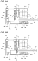
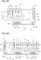
- FIGS. 8A to 8D are front views illustrating modifications of the stapler of the present illustrative embodiment.
- the single motor 51 is provided between the driver unit 2 and the coupling portion 100, specifically, between the driver unit 2 and the first link 54 configuring the coupling portion 100 as well as the gear 53 configuring the transmission unit 102.
- the single motor 51 is provided to an intermediate portion of the coupling portion 100 and is configured to operate the driver unit 2 and the bending unit 3.
- the output shaft of the motor 51 may protrude outward, and a gear of the motor 51 may mesh with the gear 53 directly or via another gear.
- the single motor 51 is provided between the coupling portion 100 and the bending unit 3 and is configured to operate the driver unit 2 and the bending unit 3.
- the transmission unit 101 may transmit the driving force of the motor 51 to the driver unit 2 via the coupling portion 100.
- the coupling portion 100 is not limited to a link, and may be a gear group or the like that couples the driver unit 2 and the bending unit 3 to enable transmission unit of a driving force.
- the single motor 51 when a side on which the coupling portion 100 (first link 54) is provided is one side in the direction along the sheet surface of the sheet P, the single motor 51 is provided on the other side in the direction along the sheet surface of the sheet P with the driver unit 2 interposed in between.
- the single motor 51 is configured to operate the driver unit 2 and the bending unit 3.
- the coupling portion 100 may be provided on the one side in the direction along the sheet surface of the sheet P with the first driver unit 21 and the second driver unit 22 interposed in between, and the single motor 51 may be provided on the other side.
- the single motor 51 may be provided between the first driver unit 21 and the second driver unit 22.
Landscapes
- Engineering & Computer Science (AREA)
- Mechanical Engineering (AREA)
- Life Sciences & Earth Sciences (AREA)
- Forests & Forestry (AREA)
- Portable Nailing Machines And Staplers (AREA)
- Dovetailed Work, And Nailing Machines And Stapling Machines For Wood (AREA)
- Folding Of Thin Sheet-Like Materials, Special Discharging Devices, And Others (AREA)
Abstract
Description
- The present disclosure relates to a stapler configured to bind a bundle of sheets with a staple.
- In a clincher device of a general stapler known in the related art, a fixing clincher having a guide groove for bending and guiding a pair of staple legs inward is disposed on a back surface side of a binding sheet, and the staple legs that are driven from a front surface side of the binding sheet toward the binding sheet by an operating unit and protrude to a binding sheet lower surface side of the staple legs are engaged with the guide groove, so that the staple legs are bent and guided inward.
- In staple binding by the fixing clincher as described above, a height of a loop shape formed at base portions of the staple legs is larger than a thickness of the binding sheet, and a staple bound part has a large thickness.
- In view of this, there is proposed an electric stapler including a movable clincher that is configured to engage with staple legs protruding to a lower surface side of a binding sheet through the binding sheet and bend the staple legs from a base portion side (for example, see
JP3526682B - Further, as a saddle binding electric stapler for binding a bundle of sheets, there is proposed an electric stapler vertically and separately provided with a driver unit including a driver that drives a staple, a clincher unit including a clincher configured to bend the driven staple, and a motor provided in each of the driver unit and the clincher unit (for example, see
JP5310381B - In a saddle binding stapler used for binding a booklet, a flat clinch is desirable so that staple legs would not protrude from a fold of a spread page of the booklet. To implement the flat clinch, the staple legs are generally bent from bases using a movable clincher. However, a stapler using a movable clincher requires not only a motor for operating a driver but also a motor for operating the movable clincher.
- A general electric stapler for square binding instead of saddle binding has a small sheet passing area, and thus a clincher and a driver can be disposed close to each other. For this reason, as described in
JP3526682B JP5310381B - However, providing the motors separately leads to an increase in a size of a stapler and an increase in the number of components, resulting in an increase in costs.
- In view of this, illustrative aspects of the present disclosure provide a stapler that can operate both a driver and a clincher with one single motor even in a saddle binding stapler (that is, it can implement flat clinch) and can accordingly mitigate an increase in a size of the stapler, the number of components, and the associated costs.
- One illustrative aspect of the present disclosure provides a stapler for performing binding processing of binding a sheet with a staple, the stapler including: a driver unit provided in a position orthogonal to a sheet surface of the sheet in a case of performing the binding processing, the driver unit being configured to drive the staple to the sheet; a bending unit provided in a position facing the driver unit through the sheet in the case of performing the binding processing, the bending unit being configured to bend a staple leg of the staple that is driven by the driver unit and penetrates the sheet; a single motor configured to operate the driver unit and the bending unit; a coupling portion coupling the driver unit and the bending unit on one side in a direction orthogonal to a sheet passing direction of the sheet passing between the driver unit and the bending unit and along the sheet surface in the case of performing the binding processing; and a transmission unit configured to transmit a driving force of the motor to the driver unit and/or the bending unit via the coupling portion.
- In the present disclosure, an upstream side and a downstream side in a sheet passing direction of a sheet are opened between a driver unit and a bending unit, and the sheet can pass therethrough.
- According to the present disclosure, a driver unit and a bending unit of a stapler can be operated by a single motor and a position of a fold of a booklet can be bound with a staple, and thus costs can be reduced.
-
-
FIG. 1A is a front view illustrating an example of a stapler according to an illustrative embodiment; -
FIG. 1B is a perspective view illustrating a main portion of the example of the stapler according to the present illustrative embodiment; -
FIG. 1C is an external perspective view illustrating the example of the stapler according to the present illustrative embodiment; -
FIG. 2A is a front sectional view illustrating a main portion of an example of a bending unit of the stapler according to the present illustrative embodiment; -
FIG. 2B is a front sectional view illustrating the main portion of the example of the bending unit of the stapler according to the present illustrative embodiment; -
FIG. 3A is a front sectional view illustrating the example of the bending unit of the stapler according to the present illustrative embodiment; -
FIG. 3B is a front sectional view illustrating the example of the bending unit of the stapler according to the present illustrative embodiment; -
FIG. 4 is a perspective view illustrating a main portion of an example of an operating unit of the stapler according to the illustrative embodiment; -
FIG. 5A is a perspective view illustrating a main portion of a first modification of the stapler according to the present illustrative embodiment; -
FIG. 5B is a perspective view illustrating a main portion of the first modification of the stapler according to the present illustrative embodiment; -
FIG. 6A is a perspective view illustrating a main portion of a second modification of the stapler according to the present illustrative embodiment; -
FIG. 6B is a perspective view illustrating the main portion of the second modification of the stapler according to the present illustrative embodiment; -
FIG. 7A is a perspective view illustrating a main portion of the second modification of the stapler of the present illustrative embodiment; -
FIG. 7B is a perspective view illustrating the main portion of the second modification of the stapler according to the present illustrative embodiment; -
FIG. 8A is a front view illustrating a modification of the stapler according to the present illustrative embodiment; -
FIG. 8B is a front view illustrating a modification of the stapler according to the present illustrative embodiment; -
FIG. 8C is a front view illustrating a modification of the stapler according to the present illustrative embodiment; and -
FIG. 8D is a front view illustrating a modification of the stapler according to the present illustrative embodiment. - Hereinafter, an illustrative embodiment of a stapler of the present disclosure will be described with reference to the drawings.
-
FIG. 1A is a front view illustrating an example of a stapler according to the present illustrative embodiment,FIG. 1B is a perspective view illustrating a main portion of the example of the stapler according to the present illustrative embodiment, andFIG. 1C is an external perspective view illustrating the example of the stapler according to the present illustrative embodiment.FIGS. 2A and 2B are front sectional views illustrating a main portion of an example of a bending unit of the stapler according to the present illustrative embodiment, andFIGS. 3A and 3B are front sectional views illustrating the example of the bending unit of the stapler according to the present illustrative embodiment.FIG. 4 is a perspective view illustrating a main portion of an example of an operating unit of the stapler according to the present illustrative embodiment. - A
stapler 1A includes adriver unit 2, abending unit 3, acoupling portion 100,transmission units operating unit 5. Thedriver unit 2 is provided in a position orthogonal to a sheet surface of a sheet P during binding processing of binding the sheet P with a staple 11, and is configured to drive the staple 11 to the sheet P. Thebending unit 3 is provided in a position facing thedriver unit 2 through the sheet P during the above-described binding processing, and is configured to bend a pair ofstaple legs driver unit 2 and penetrates the sheet P. Thecoupling portion 100 couples thedriver unit 2 and thebending unit 3 on one side in a direction orthogonal to a sheet passing direction of the sheet P passing between thedriver unit 2 and thebending unit 3 and along the sheet surface of the sheet P before and after the above-described binding processing. The sheet passing direction of the sheet P is indicated by an arrow F. An arrow C indicates the direction along the sheet surface of the sheet P. Theoperating unit 5 includes asingle motor 51. Thesingle motor 51 is configured to operate thedriver unit 2 and thebending unit 3. Thetransmission unit 101 is configured to transmit a driving force of themotor 51 to thedriver unit 2. Thetransmission unit 102 is configured to transmit the driving force of themotor 51 to thecoupling portion 100. Thetransmission unit 103 is configured to transmit the driving force of themotor 51 to thebending unit 3 via thecoupling portion 100. Thecoupling portion 100 and thetransmission units driver unit 2 and thebending unit 3 face each other across asheet area 10. Thestapler 1A includes aframe 10a, aframe 10b, and a pair offrames frame 10a and theframe 10b. Thesheet area 10 is formed by a space between thedriver unit 2 and thebending unit 3. The space between thedriver unit 2 and thebending unit 3 is defined by theframe 10a, theframe 10b, and the pair offrames frame 10a and theframe 10b. - The
frame 10a is provided with thedriver unit 2 therein, which forms an exterior of thedriver unit 2. Theframe 10a is further provided with themotor 51 and thetransmission units frame 10b is provided with thebending unit 3 inside, which forms an exterior of thebending unit 3. Theframe 10b further includes thetransmission unit 103 therein. Theframe 10c connects theframe 10a and theframe 10b on the one side in the direction orthogonal to the sheet passing direction of the sheet P indicated by the arrow F and along the sheet surface of the sheet P. Theframe 10c is provided with thecoupling portion 100 therein. Theframe 10d connects theframe 10a and theframe 10b on the other side in the direction orthogonal to the sheet passing direction of the sheet P and along the sheet surface of the sheet P. Thedriver unit 2 does not protrude from theframe 10a to an inside of thesheet area 10 except when the sheet P is clamped between thedriver unit 2 and thebending unit 3. Themotor 51 and thetransmission units frame 10a to the inside of thesheet area 10. Thebending unit 3 and thetransmission unit 103 do not protrude from theframe 10b to the inside of thesheet area 10. Thecoupling portion 100 does not protrude from theframe 10c to the inside of thesheet area 10. - Accordingly, the
sheet area 10 is open upstream and downstream of the sheet passing direction of the sheet P, allowing the sheet P to pass therethrough. Two sides of thesheet area 10 in the direction orthogonal to the sheet passing direction of the sheet P and along the sheet surface of the sheet P are blocked by theframes frame 10c and theframe 10d face each other at an interval larger than a maximum width of the sheet P that can pass therethrough. Theframe 10a and theframe 10b face each other at an interval larger than a thickness of a stack of a maximum number of sheets P that can be bound. Thedriver unit 2 and thebending unit 3 are coupled to each other via theframes - The
driver unit 2 includes afirst driver unit 21, asecond driver unit 22, and apower transmission unit 23. Thefirst driver unit 21 is an example of a driver unit or a first driver unit. The staple 11 driven by thefirst driver unit 21 is an example of a first staple, and the pair ofstaple legs first driver unit 21 are examples of staple legs of the first staple. Thesecond driver unit 22 is an example of a second driver unit. The staple 11 driven by thesecond driver unit 22 is an example of a second staple. The pair ofstaple legs second driver unit 22 are examples of staple legs of the second staple. - The
first driver unit 21 includes adriver plate 21a and apower transmission unit 21b. Thedriver plate 21a is supported in a manner of being movable along an extending direction of the pair ofstaple legs staple 11. Thepower transmission unit 21b includes, for example, a gear that makes up a cam and a link that is displaceable by rotation of the gear. Thepower transmission unit 21b is configured to transmit movement of theoperating unit 5 to thedriver plate 21a. Thedriver plate 21a is configured to be operated by theoperating unit 5 via thepower transmission unit 21b and to drive thestaple 11. Thefirst driver unit 21 includes a forming plate for shaping thestaple 11. Thefirst driver unit 21 further includes an attachment portion to which a cartridge accommodating the staple 11 before shaping is removably mounted. - The
second driver unit 22 includes adriver plate 22a and apower transmission unit 22b. Thedriver plate 22a is supported in a manner of being movable along the extending direction of the pair ofstaple legs staple 11. Thepower transmission unit 22b includes, for example, a gear that makes up a cam and a link that is displaceable by rotation of the gear. Thepower transmission unit 22b is configured to transmit the movement of theoperating unit 5 to thedriver plate 22a. Thedriver plate 22a is configured to be operated by theoperating unit 5 via thepower transmission unit 22b and to drive thestaple 11. Thesecond driver unit 22 includes a forming plate for shaping thestaple 11. Thesecond driver unit 22 further includes an attachment portion to which a cartridge accommodating the staple 11 before shaping is removably mounted. - The
power transmission unit 23 is configured by, for example, a shaft connecting thepower transmission unit 21b of thefirst driver unit 21 and thepower transmission unit 22b of thesecond driver unit 22, etc. Thepower transmission unit 23 is configured to transmit the movement transmitted from theoperating unit 5 to thepower transmission unit 21b to thepower transmission unit 22b. Accordingly, thedriver plate 21a and thedriver plate 22a interlock. - The
first driver unit 21 and thesecond driver unit 22 are arranged side by side in the direction orthogonal to the sheet passing direction of the sheet P and along the sheet surface of the sheet P. Astaple crown 11c of the staple 11 driven by thefirst driver unit 21 and thesecond driver unit 22 extends in the direction orthogonal to the sheet passing direction of the sheet P and along the sheet surface of the sheet P. - The
bending unit 3 includes afirst bending unit 31 and asecond bending unit 32. Thefirst bending unit 31 is an example of a bending unit or a first bending unit. Thesecond bending unit 32 is an example of a second bending unit. Thefirst bending unit 31 includes afirst clincher 31a, asecond clincher 31b, and a clampingportion 33a. Thefirst bending unit 31 faces thefirst driver unit 21 with thesheet area 10 interposed therebetween. The clampingportion 33a is a surface facing thefirst driver unit 21. The clampingportion 33a is provided on aframe 34a of thefirst bending unit 31. The clampingportion 33a has anopening 35a through which thefirst clincher 31a and thesecond clincher 31b are exposed. - The
first clincher 31a includes a receivingportion 36a and an actedportion 37a. Thefirst clincher 31a is supported by theframe 34a in a manner of being rotatable about ashaft 38a as a fulcrum. Thefirst clincher 31a abuts against thestaple leg 11a during the above-described binding processing, and pivots in a bending direction of thestaple leg 11a about theshaft 38a as the fulcrum. The rotation is also referred to as pivoting. The pivoting refers to rotation in a range of less than 360°. Thefirst clincher 31a is movable between a bending standby position illustrated inFIG. 2A and a bending position illustrated inFIG. 2B by being rotatable about theshaft 38a as the fulcrum. - The receiving
portion 36a is provided at a portion that moves in directions toward and away from the clampingportion 33a by the rotation of thefirst clincher 31a about theshaft 38a as the fulcrum. The receivingportion 36a is exposed to theopening 35a of the clampingportion 33a. - In a state in which the
first clincher 31a is moved to the bending standby position, the receivingportion 36a is inclined in the direction away from the clampingportion 33a as approaching a tip end side facing thesecond clincher 31b from theshaft 38a. - The receiving
portion 36a moves in a first direction indicated by an arrow A1, which is the direction toward the clampingportion 33a from the bending standby position, by the rotation of thefirst clincher 31a with theshaft 38a as the fulcrum. The receivingportion 36a moves from the bending position in a second direction indicated by an arrow A2 opposite to the arrow A1, which is the direction away from the clampingportion 33a. - The
first clincher 31a has atip end 300a. The actedportion 37a is provided at a portion opposite to the receivingportion 36a between thetip end 300a and theshaft 38a. Thefirst clincher 31a moves from the bending standby position to the bending position by receiving a force for pressing the actedportion 37a. - The
second clincher 31b includes a receivingportion 36b and an actedportion 37b. Thesecond clincher 31b is provided on a side of the clampingportion 33a that is opposite to a side facing thefirst driver unit 21. Thesecond clincher 31b is supported by theframe 34a in a manner of being rotatable about ashaft 38b as a fulcrum. - The
second clincher 31b abuts against thestaple leg 11b during the above-described binding processing, and pivots in a bending direction of thestaple leg 11b about theshaft 38b as the fulcrum. Thesecond clincher 31b is movable between the bending standby position illustrated inFIG. 2A and the bending position illustrated inFIG. 2B by being rotatable about theshaft 38b as the fulcrum. - The receiving
portion 36b is provided at a portion that moves in directions toward and away from the clampingportion 33a by the rotation of thesecond clincher 31b with theshaft 38b as the fulcrum. The receivingportion 36b is exposed to theopening 35a of the clampingportion 33a. - In a state where the
second clincher 31b is moved to the bending standby position, the receivingportion 36b is inclined in the direction away from the clampingportion 33a as approaching a tip end side facing thefirst clincher 31a from theshaft 38b. - The receiving
portion 36b moves in the first direction indicated by the arrow A1, which is the direction toward the clampingportion 33a from the bending standby position, by the rotation of thesecond clincher 31b with theshaft 38b as the fulcrum. The receivingportion 36b moves from the bending position in the second direction indicated by the arrow A2, which is the direction away from the clampingportion 33a. - The
second clincher 31b has atip end 300b. The actedportion 37b is provided at a portion opposite to the receivingportion 36b between thetip end 300b and theshaft 38b. Thesecond clincher 31b is moves from the bending standby position to the bending position by receiving a force for pressing the actedportion 37b. When thefirst clincher 31a moves to the bending standby position, thesecond clincher 3 1b interlocks and moves to the bending standby position. When thefirst clincher 31a moves to the bending position, thesecond clincher 31b interlocks and moves to the bending position. Theshafts - The
second bending unit 32 includes afirst clincher 32a, asecond clincher 32b, and a clampingportion 33b. Thefirst clincher 32a and thesecond clincher 32b of thesecond bending unit 32 are examples of a pair of second clinchers. Thesecond bending unit 32 faces thesecond driver unit 22 with thesheet area 10 interposed therebetween. The clampingportion 33b is a surface facing thesecond driver unit 22. The clampingportion 33b is provided on aframe 34b of thesecond bending unit 32. The clampingportion 33b has anopening 35b through which thefirst clincher 32a and thesecond clincher 32b are exposed. - The
first clincher 32a and thesecond clincher 32b of thesecond bending unit 32 have the same configuration as thefirst clincher 31a and thesecond clincher 31b of thefirst bending unit 31. - The
operating unit 5 includes thesingle motor 51 described above. Thecoupling portion 100 includes afirst link 54. Thetransmission unit 101 includes agear group 51b that meshes with agear 51a of themotor 51, and ashaft 51c that rotates together with thegear group 51b. Thetransmission unit 102 includes agear 53 and agear 52 that meshes with thegear 53. Thegear 52 is attached to theshaft 51c. In this way, thetransmission unit 101 and thetransmission unit 102 may share a part of a gear, a shaft, and the like. Thetransmission unit 103 includes asecond link 55, athird link 55B, and aconversion unit 55C. Themotor 51 is provided inside theframe 10a on a side of thefirst driver unit 21 that is opposite to a side on which thesecond driver unit 22 is provided along a direction intersecting the surface of the sheet P passing through thesheet area 10. Thetransmission unit 101 is configured to transmit rotation of themotor 51 to thepower transmission unit 21b of thefirst driver unit 21 via thegear group 51b, theshaft 51c, and the like. Thetransmission unit 102 is configured to transmit the rotation of themotor 51 to thefirst link 54 configuring thecoupling portion 100 via thegear group 51b, theshaft 51c, thegear 52, and thegear 53. Thetransmission units - The
gear 53 is provided inside theframe 10a of thedriver unit 2. Thegear 53 is provided outside themotor 51 relative to thefirst driver unit 21. In the present illustrative embodiment, an output shaft of themotor 51 protrudes inward toward thefirst driver unit 21, and thegear 51a is provided on an inner side facing thefirst driver unit 21. For this reason, the rotation of themotor 51 is transmitted via thetransmission unit 102 including theshaft 51c, which extends outward of themotor 51 relative to thefirst driver unit 21, and thegear 53 rotates. Thegear 53 includes acam groove 53a that draws a trajectory whose distance from a rotation center changes. Thecam groove 53a is an example of a cam. Thecam groove 53a extends in a circumferential direction of thegear 53. - The
first link 54 is an example of a link and a first link. Thefirst link 54 is provided inside theframe 10c on the one side in the direction orthogonal to the sheet passing direction of the sheet P indicated by the arrow F and along the sheet surface of the sheet P relative to thesheet area 10. Thefirst link 54 does not protrude toward thesheet area 10 or interfere with sheet passage. Thefirst link 54 extends along a direction in which thedriver unit 2 and thebending unit 3 face each other. Thefirst link 54 is supported in a manner of being movable in a third direction indicated by an arrow B1 and a fourth direction indicated by an arrow B2. The third direction is along the direction in which thedriver unit 2 and thebending unit 3 face each other, and the fourth direction is in the opposite direction to the third direction. The third direction and the fourth direction are directions orthogonal to the sheet surface of the sheet P passing through thesheet area 10, and in this example, they are in an upper-lower direction (e.g., vertical direction). - The
first link 54 includes afirst cam follower 54a and asecond cam follower 54b. Thefirst cam follower 54a is provided on adriver unit 2 side along the direction in which thefirst link 54 extends. When thegear 53 rotates, thefirst cam follower 54a follows the trajectory of thecam groove 53a, so that thefirst link 54 moves in the third direction and the fourth direction. Thesecond cam follower 54b is an example of theconversion unit 55C, and is provided on abending unit 3 side along the direction in which thefirst link 54 extends. - The
second link 55 is an example of a link and a second link. Thesecond link 55 is provided inside theframe 10b of thebending unit 3. Thethird link 55B is an example of a second transmission unit, a link, and a third link. Thethird link 55B is provided inside theframe 10b of thebending unit 3. Thethird link 55B is provided on an extension line of thesecond link 55. Thesecond link 55 and thethird link 55B extend along a direction in which thefirst bending unit 31 and thesecond bending unit 32 are arranged side by side. Thesecond link 55 and thethird link 55B are supported in a manner of being movable in a fifth direction indicated by an arrow C1 and a sixth direction indicated by an arrow C2. The fifth direction is along the direction in which thefirst bending unit 31 and thesecond bending unit 32 are arranged side by side, and the sixth direction is in the opposite direction to the fifth direction. The fifth direction and the sixth direction are directions along the sheet surface of the sheet P passing through thesheet area 10, and in this example, they are in a horizontal direction. - The
second link 55 includes acam groove 55a and actingportions third link 55B includes actingportions - The
cam groove 55a is an example of theconversion unit 55C. Thecam groove 55a extends obliquely relative to the moving direction of thefirst link 54 and the moving directions of thesecond link 55 and thethird link 55B. Thesecond cam follower 54b of thefirst link 54 is inserted into thecam groove 55a. - The acting
portion 56a is an example of a protrusion or a first protrusion. The actingportion 56a faces the actedportion 37a of thefirst clincher 31a of thefirst bending unit 31. The actingportion 56b is an example of a protrusion or a first protrusion. The actingportion 56b faces the actedportion 37b of thesecond clincher 31b of thefirst bending unit 31. The actingportion 56c is an example of a second protrusion. The actingportion 56c faces the actedportion 37a of thefirst clincher 32a of thesecond bending unit 32. The actingportion 56d is an example of a second protrusion. The actingportion 56d faces the actedportion 37b of thesecond clincher 32b of thesecond bending unit 32. -
FIG. 3A illustrates a state in which thefirst clincher 31a and thesecond clincher 31b of thefirst bending unit 31 and thefirst clincher 32a and thesecond clincher 32b of thesecond bending unit 32 are in the bending standby position as illustrated inFIG. 2A . When thefirst link 54 moves in the third direction indicated by the arrow B1 from this state, thesecond cam follower 54b of thefirst link 54 presses a lower surface of theinclined cam groove 55a of thesecond link 55. Accordingly, thesecond link 55 moves in the fifth direction indicated by the arrow C1. -
FIG. 3B illustrates a state in which thefirst clincher 31a and thesecond clincher 31b of thefirst bending unit 31 and thefirst clincher 32a and thesecond clincher 32b of thesecond bending unit 32 are in the bending positions as illustrated inFIG. 2B . When thefirst link 54 moves in the fourth direction indicated by the arrow B2 from this state, thesecond cam follower 54b of thefirst link 54 presses an upper surface of theinclined cam groove 55a of thesecond link 55. Accordingly, thesecond link 55 moves in the sixth direction indicated by the arrow C2. - When the
gear 53 rotates by a prescribed angle in a prescribed direction, thefirst cam follower 54a follows the trajectory of thecam groove 53a, so that thefirst link 54 moves in the third direction or the fourth direction. From a usage form of thestapler 1A, the moving direction of thefirst link 54 is the upper-lower direction, and the moving direction of thesecond link 55 is the horizontal direction. Accordingly, rotation operation of thegear 53 is converted into a linear motion of thefirst link 54 in the upper-lower direction, which is orthogonal to the sheet surface of the sheet P passing through thesheet area 10, and the linear motion of thefirst link 54 in the upper-lower direction (which may be referred to as the vertical linear motion of the first link 54) is converted into a linear motion of thesecond link 55 in the horizontal direction, which is aligned with the sheet surface of the sheet P passing through thesheet area 10. That is, the vertical linear motion of thefirst link 54 is converted into a horizontal linear motion of thesecond link 55. - As described above, the
first link 54 is located outside thesheet area 10 where the sheet P is located during the binding processing on the one side in the direction orthogonal to the sheet passing direction of the sheet P passing between thedriver unit 2 and thebending unit 3 and along the sheet surface of the sheet P before and after the binding processing. Thefirst link 54 displaces in a direction orthogonal to the sheet surface of the sheet P, following thecam groove 53a of thegear 53 that is an example of a cam. Thesecond link 55 is located below thesheet area 10. Thesecond link 55 moves in a direction along the sheet surface of the sheet P and is configured to pivot thefirst clincher 31a and thesecond clincher 31b of thefirst bending unit 31. Thethird link 55B is located below thesheet area 10. Thethird link 55B moves in the direction along the sheet surface of the sheet P and is configured to pivot thefirst clincher 32a and thesecond clincher 32b of thesecond bending unit 32. Theconversion unit 55C is located between thefirst link 54 and thesecond link 55. Theconversion unit 55C is configured to convert the displacement of thefirst link 54 in the direction orthogonal to the sheet surface of the sheet P into the displacement of thesecond link 55 in the direction along the sheet surface of the sheet P. - The
bending unit 3 includes asupport member 39. Thesupport member 39 supports thesecond link 55 from below to prevent thesecond link 55 from bending. - In the
stapler 1A, the sheet P is conveyed until a center of the sheet P orthogonal to the sheet passing direction of the sheet P passing through thesheet area 10 is aligned with a driveing position of the staple 11 by thefirst driver unit 21 and thesecond driver unit 22. In a case where this alignment is achieved, the conveying of the sheet P is stopped. - By the
motor 51 of theoperating unit 5 being rotated, thedriver plate 21a of thefirst driver unit 21 moves in the first direction indicated by the arrow A1, which is the driveing direction. Thedriver plate 22a of thesecond driver unit 22 interlocks with thedriver plate 21a and moves in the driveing direction. - Hereinafter, the operation will be described using the
first driver unit 21 and thefirst bending unit 31 as an example. Thedriver plate 21a moves in the driveing direction, so that thestaple crown 11c of the staple 11 is pressed and thestaple legs - The
staple leg 11a penetrating the sheet P comes into contact with the receivingportion 36a of thefirst clincher 31a of thefirst bending unit 31. Thestaple leg 11b penetrating the sheet P comes into contact with the receivingportion 36b of thesecond clincher 31b of thefirst bending unit 31. - When the
staple crown 11c of the staple 11 is further pressed by thedriver plate 21a, thestaple leg 11a penetrating the sheet P is guided along the inclined receivingportion 36a and bent inward by the movement of thefirst clincher 31a to the bending standby position. Thestaple leg 11b penetrating the sheet P is guided along the inclined receivingportion 36b and bent inward by the movement of thesecond clincher 3 1b to the bending standby position. - When the
motor 51 of theoperating unit 5 rotates, thegear 53 rotates. When thedriver plate 21a moves in the driveing direction until thestaple crown 11c of the staple 11 comes into contact with a front surface of the sheet P, thegear 53 moves thefirst link 54 in the third direction indicated by the arrow B1. - When the
gear 53 further rotates, thefirst link 54 moves in the third direction, so that thesecond cam follower 54b of thefirst link 54 presses theinclined cam groove 55a of thesecond link 55. Accordingly, thesecond link 55 moves in the fifth direction indicated by the arrow C1. - When the
second link 55 moves in the fifth direction, the actingportion 56a presses the actedportion 37a of thefirst clincher 31a of thefirst bending unit 31. Accordingly, thefirst clincher 31a moves from the bending standby position to the bending position by receiving a force for pressing the actedportion 37a. When thefirst clincher 31a moves to the bending position, the receivingportion 36a presses thestaple leg 11a toward a back surface of the sheet P, and bends a tip end of thestaple leg 11a toward the back surface of the sheet P. - When the
second link 55 moves in the fifth direction, the actingportion 56b presses the actedportion 37b of thesecond clincher 31b of thefirst bending unit 31. Accordingly, thesecond clincher 31b moves from the bending standby position to the bending position by receiving a force for pressing the actedportion 37b. When thesecond clincher 31b moves to the bending position, the receivingportion 36b presses thestaple leg 11b toward the back surface of the sheet P, and bends a tip end of thestaple leg 11b toward the back surface of the sheet P. - The operation is described with the
first driver unit 21 and thefirst bending unit 31 as an example, and operation of thesecond driver unit 22 and thesecond bending unit 32 is the same. - The
coupling portion 100 is provided with thefirst link 54 on the one side outside thesheet area 10 in the direction orthogonal to the sheet passing direction of the sheet P indicated by the arrow F and along the sheet surface of the sheet P. Accordingly, thesheet area 10 is open upstream and downstream of the sheet passing direction of the sheet P, allowing the sheet P to pass therethrough. - Accordingly, the
stapler 1A can align the driveing position of the staple 11 driven by thefirst driver unit 21 and thesecond driver unit 22 with the center of the sheet P orthogonal to the sheet passing direction of the sheet P. Accordingly, thestapler 1A can bind the sheet P in a form called saddle binding. - Further, the
stapler 1A includes themotor 51 in thedriver unit 2, and is configured to operate thefirst driver unit 21 and thesecond driver unit 22 and to transmit a driving force of themotor 51 to thebending unit 3 through thefirst link 54, so that the clinchers can be operated. - Accordingly, in the
stapler 1A that can bind the sheet P in a form called saddle binding, an amount by which the bent staple legs protrude on the back surface of the sheet can be reduced. The tip ends of the staple legs can be directed to the back surface of the sheet. Further, costs can be reduced since thedriver unit 2 and thebending unit 3 can be operated by thesingle motor 51. - The
first link 54 moves (linearly moves) along theframe 10c. Accordingly, space required for the movement of thefirst link 54 does not spread in directions toward and away from thesheet area 10, and an increase in a size of the stapler can be suppressed. Further, thegear 53 is provided in thedriver unit 2. Accordingly, no space for thegear 53 is necessary between theframe 10c and thesheet area 10, and an increase in the size of the stapler can be suppressed. Thesecond link 55 and thethird link 55B move (linearly move) along theframe 10b. Accordingly, space required for the movement of thesecond link 55 and thethird link 55B does not spread in directions toward and away from thesheet area 10, and an increase in the size of the stapler can be suppressed. - When the number of sheets P to be bound increases, a load applied when the
staple legs staple legs staple leg 11a of the staple 11 penetrating the bundle of sheets displaces to a position in which the tip end cannot come into contact with the receivingportion 36a of thefirst clincher 31a, thestaple leg 11a cannot be bent. Similarly, when the tip end of thestaple leg 11b of the staple 11 penetrating the bundle of sheets displaces to a position in which the tip end cannot come into contact with the receivingportion 36b of thesecond clincher 3 1b, thestaple leg 11b cannot be bent. - On the other hand, the receiving
portion 36a moves in the directions toward and away from the clampingportion 33a by the rotation of thefirst clincher 31a with theshaft 38a as the fulcrum. In a state in which thefirst clincher 31a is moved to the bending standby position, the receivingportion 36a is separated from the clampingportion 33a. Accordingly, increasing a length of the receivingportion 36a can increase a range in which thestaple leg 11a can come into contact with the receivingportion 36a. On the other hand, in a state in which thefirst clincher 31a moves to the bending position, the receivingportion 36a approaches the clampingportion 33a. Accordingly, thestaple leg 11a can be pressed against the back surface of the sheet P even when the receivingportion 36a has an increased length. Similarly, the receivingportion 36b moves in the directions toward and away from the clampingportion 33b by the rotation of thesecond clincher 31b about theshaft 38b as the fulcrum. In a state in which thesecond clincher 31b moves to the bending standby position, the receivingportion 36b is separated from the clampingportion 33b. Accordingly, increasing a length of the receivingportion 36b can increase a range in which thestaple leg 11b can come into contact with the receivingportion 36b. On the other hand, in a state in which thesecond clincher 31b moves to the bending position, the receivingportion 36b approaches the clampingportion 33b. Accordingly, thestaple leg 11b can be pressed against the back surface of the sheet P even when the receivingportion 36b has an increased length. -
FIGS. 5A and 5B are perspective views of main portions of a first modification of the stapler according to the present illustrative embodiment. Astapler 1B includes a sheet area, a driver unit, which are not illustrated, abending unit 3B, and anoperating unit 5B. Thebending unit 3B includes thefirst clincher 31a, thesecond clincher 31b, and a first actedportion 37c. - The
first clincher 31a includes the receivingportion 36a and the second actedportion 37a. Thefirst clincher 31a is rotatably supported about theshaft 38a as a fulcrum. Thefirst clincher 31a rotates about theshaft 38a as the fulcrum and moves between a bending position illustrated inFIG. 5A and a bending standby position illustrated inFIG. 5B . - The
second clincher 31b includes the receivingportion 36b and the second actedportion 37b. Thesecond clincher 31b is rotatably supported about theshaft 38b as a fulcrum. Thesecond clincher 31b rotates about theshaft 38b as the fulcrum and moves between the bending position illustrated inFIG. 5A and the bending standby position illustrated inFIG. 5B . - The first acted
portion 37c rotates about ashaft 37d as a fulcrum and presses the second actedportion 37a of thefirst clincher 31a and the second actedportion 37b of thesecond clincher 31b. Thefirst clincher 31a moves from the bending standby position to the bending position by receiving a force for pressing the second actedportion 37a. Thesecond clincher 31b moves from the bending standby position to the bending position by receiving a force for pressing the second actedportion 37b. - The
operating unit 5B includes arotary body 53B, afirst link 57, and asecond link 58. Therotary body 53B is an example of a transmission unit. Therotary body 53B includes acam 53c that draws a trajectory whose distance from a rotation center changes. Thecam 53c extends in a circumferential direction of therotary body 53B. - The
first link 57 is an example of a coupling portion and a link. Thefirst link 57 includes acam follower 57a and an engagedportion 57b. When therotary body 53B rotates, thecam follower 57a follows the trajectory of thecam 53c, so that thefirst link 57 rotates about a shaft (not illustrated) inserted into thesupport hole 57c as a fulcrum. - The
second link 58 is an example of a transmission unit and a link. Thesecond link 58 includes an engagingportion 58a, ashaft 58b, and an actingportion 58c. The engagingportion 58a is inserted into the engagedportion 57b of thefirst link 57. The actingportion 58c faces the first actedportion 37c, and rotates about theshaft 58b as a fulcrum when thesecond link 58 rotates. - Accordingly, when the
rotary body 53B rotates, thefirst link 57 displaces (rotates) following thecam 53c. Further, thesecond link 58 displaces (rotates) following the displacement of thefirst link 57. - When the
second link 58 displaces (rotates), the actingportion 58c rotates about theshaft 58b as the fulcrum. When the actingportion 58c rotates, the first actedportion 37c presses the second actedportion 37a of thefirst clincher 31a and the second actedportion 37b of thesecond clincher 3 1b by rotating about theshaft 37d as the fulcrum. Thefirst clincher 3 1a moves from the bending standby position to the bending position by receiving a force for pressing the second actedportion 37a. Thesecond clincher 31b moves from the bending standby position to the bending position by receiving a force for pressing the second actedportion 37b. -
FIGS. 6A, 6B ,7A, and 7B are perspective views of a main portion of a second modification of the stapler according to the present illustrative embodiment.FIGS. 6A and 6B are perspective views of a main portion of abending unit 3C viewed from a front surface of the stapler.FIGS. 7A and 7B are perspective views of the main portion of thebending unit 3C viewed from a back surface of the stapler. - The
bending unit 3C includes thefirst clincher 31a and thesecond clincher 31b. Thefirst clincher 31a includes the receivingportion 36a and an actedportion 37e. Thefirst clincher 31a is rotatably supported about theshaft 38a as a fulcrum. Thefirst clincher 31a rotates about theshaft 38a as the fulcrum and moves between a bending standby position illustrated inFIGS. 6A and7A and a bending position illustrated inFIGS. 6B and7B . The actedportion 37e is configured by a shaft protruding from thefirst clincher 31a. - The
second clincher 31b includes the receivingportion 36b and an actedportion 37f. Thesecond clincher 31b is rotatably supported about theshaft 38b as a fulcrum. Thesecond clincher 31b rotates about theshaft 38b as the fulcrum and moves between the bending standby position illustrated inFIGS. 6A and7A and the bending position illustrated inFIGS. 6B and7B . The actedportion 37f is configured by a shaft protruding from thefirst clincher 31a. - The
second link 59 is an example of a transmission unit and a link. Thesecond link 59 is supported in a manner of being movable in the fifth direction indicated by the arrow C1 and the sixth direction indicated by the arrow C2 in the opposite direction to the fifth direction. Thesecond link 59 includes actingportions - The acting
portion 59a is configured by a cam groove extending along the fifth direction and the sixth direction and having an inclined surface along a direction in which thefirst clincher 31a rotates. The actingportion 59a receives the actedportion 37e of thefirst clincher 31a. The actingportion 59b is configured by a cam groove extending along the fifth direction and the sixth direction and having an inclined surface along a direction in which thesecond clincher 3 1b rotates. The actingportion 59b receives the actedportion 37f of thesecond clincher 31b. - When the
second link 59 moves in the fifth direction, the actingportion 59a presses the actedportion 37e of thefirst clincher 31a with the inclined surface. Accordingly, thefirst clincher 31a moves from the bending standby position to the bending position by receiving a force for pressing the actedportion 37e. When thesecond link 59 moves in the fifth direction, the actingportion 59b presses the actedportion 37f of thesecond clincher 3 1b with the inclined surface. Accordingly, thesecond clincher 31b moves from the bending standby position to the bending position by receiving a force for pressing the actedportion 37f. - In the
bending unit 3C, thefirst clincher 31a and thesecond clincher 31b can overlap thesecond link 59 along axial directions of therespective shafts bending unit 3C along a direction in which thefirst clincher 31a and thesecond clincher 31b rotate can be reduced. -
FIGS. 8A to 8D are front views illustrating modifications of the stapler of the present illustrative embodiment. InFIG. 1A and the like described above, thesingle motor 51 is provided between thedriver unit 2 and thecoupling portion 100, specifically, between thedriver unit 2 and thefirst link 54 configuring thecoupling portion 100 as well as thegear 53 configuring thetransmission unit 102. On the other hand, in astapler 1C illustrated inFIG. 8A , thesingle motor 51 is provided to an intermediate portion of thecoupling portion 100 and is configured to operate thedriver unit 2 and thebending unit 3. In this case, the output shaft of themotor 51 may protrude outward, and a gear of themotor 51 may mesh with thegear 53 directly or via another gear. In astapler 1D illustrated inFIG. 8B , thesingle motor 51 is provided between thecoupling portion 100 and thebending unit 3 and is configured to operate thedriver unit 2 and thebending unit 3. In the configuration in which themotor 51 is provided between thecoupling portion 100 and thebending unit 3, thetransmission unit 101 may transmit the driving force of themotor 51 to thedriver unit 2 via thecoupling portion 100. Thecoupling portion 100 is not limited to a link, and may be a gear group or the like that couples thedriver unit 2 and thebending unit 3 to enable transmission unit of a driving force. - Further, in a
stapler 1E illustrated inFIG. 8C , when a side on which the coupling portion 100 (first link 54) is provided is one side in the direction along the sheet surface of the sheet P, thesingle motor 51 is provided on the other side in the direction along the sheet surface of the sheet P with thedriver unit 2 interposed in between. Thesingle motor 51 is configured to operate thedriver unit 2 and thebending unit 3. In this case, in the configuration in which thedriver unit 2 includes thefirst driver unit 21 and thesecond driver unit 22, thecoupling portion 100 may be provided on the one side in the direction along the sheet surface of the sheet P with thefirst driver unit 21 and thesecond driver unit 22 interposed in between, and thesingle motor 51 may be provided on the other side. As illustrated inFIG. 8D , in astapler 1F in which thedriver unit 2 includes thefirst driver unit 21 and thesecond driver unit 22, thesingle motor 51 may be provided between thefirst driver unit 21 and thesecond driver unit 22.
Claims (11)
- A stapler for performing binding processing of binding a sheet with a staple, the stapler comprising:a driver unit provided in a position orthogonal to a sheet surface of the sheet in a case of performing the binding processing, the driver unit being configured to drive the staple to the sheet;a bending unit provided in a position facing the driver unit through the sheet in the case of performing the binding processing, the bending unit being configured to bend a staple leg of the staple that is driven by the driver unit and penetrates the sheet;a single motor configured to operate the driver unit and the bending unit;a coupling portion coupling the driver unit and the bending unit on one side in a direction orthogonal to a sheet passing direction of the sheet passing between the driver unit and the bending unit and along the sheet surface in the case of performing the binding processing; anda transmission unit configured to transmit a driving force of the motor to the driver unit and/or the bending unit via the coupling portion.
- The stapler according to claim 1, wherein the transmission unit is configured to transmit the driving force of the motor to the bending unit via the coupling portion.
- The stapler according to claim 1, wherein the motor is provided in a freely selected position between the driver unit and the coupling portion, between the coupling portion and the bending unit to an intermediate portion of the coupling portion, or on another side in a direction along the sheet surface with the driver unit interposed in between.
- The stapler according to claim 1, wherein the motor is provided between the driver unit and the coupling portion.
- The stapler according to claim 1,wherein the bending unit includes a pair of clinchers that abut against the staple leg during the binding processing, each of the pair of clinchers having a tip end that is pivotable in a bending direction of the staple leg about a shaft as a fulcrum, andwherein the transmission unit is configured to pivot the clinchers.
- The stapler according to claim 5,wherein the coupling portion includes a first link located on the one side outside a sheet area in which the sheet is located in the case of performing the binding processing, the first link being displaceable in a direction orthogonal to the sheet surface, andwherein the transmission unit includes:a cam configured to rotate by receiving the driving force of the motor and displace the first link in the above-described direction;a second link located below the sheet area and configured to move in a direction along the sheet surface and to pivot the clinchers; anda conversion unit located between the first link and the second link and configured to convert displacement of the first link in the direction orthogonal to the sheet surface into displacement of the second link in the direction along the sheet surface.
- The stapler according to claim 6,wherein the second link has a protrusion that protrudes in the bending direction and is abuttable between the shaft of the clincher and the tip end, andwherein the protrusion is configured to pivot the clincher in the bending direction while abutting against the clincher as the second link is displaced in the direction along the sheet surface.
- The stapler according to claim 7, further comprising:a second driver unit adjacent to the driver unit on the other side in the direction orthogonal to the sheet passing direction and along the sheet surface, the second driver unit being configured to drive a second staple to the sheet; anda second bending unit provided in a position facing the second driver unit through the sheet during the binding processing, the second bending unit being configured to bend a staple leg of the second staple that is driven by the second driver unit and penetrates the sheet,wherein the single motor is further configured to operate the second driver unit, andwherein the transmission unit includes a second transmission unit that is configured to transmit the driving force of the single motor to the second bending unit.
- The stapler according to claim 8, wherein the second transmission unit includes a third link continuous with the second link and configured to move the second bending unit by displacing in the direction along the sheet surface in conjunction with the second link.
- The stapler according to claim 9,wherein the second bending unit includes a pair of second clinchers, each having a second tip end that is pivotable in a bending direction of the staple leg of the second staple with a second shaft as a fulcrum,wherein the third link has a second protrusion that protrudes in the bending direction of the staple leg of the second staple and is abuttable between the second shaft and the second tip end of the second clincher, andwherein the second protrusion is configured to rotate the second clincher in the bending direction of the staple leg of the second staple while abutting against the second clincher as the third link is displaced.
- The stapler according to claim 8, wherein the motor is provided in a position between the driver unit and the second driver unit.
Applications Claiming Priority (1)
| Application Number | Priority Date | Filing Date | Title |
|---|---|---|---|
| JP2023107868A JP2025006847A (en) | 2023-06-30 | 2023-06-30 | Stapler |
Publications (2)
| Publication Number | Publication Date |
|---|---|
| EP4484099A1 true EP4484099A1 (en) | 2025-01-01 |
| EP4484099B1 EP4484099B1 (en) | 2026-03-18 |
Family
ID=91738767
Family Applications (1)
| Application Number | Title | Priority Date | Filing Date |
|---|---|---|---|
| EP24185066.8A Active EP4484099B1 (en) | 2023-06-30 | 2024-06-27 | Stapler |
Country Status (4)
| Country | Link |
|---|---|
| US (1) | US12491657B2 (en) |
| EP (1) | EP4484099B1 (en) |
| JP (1) | JP2025006847A (en) |
| CN (1) | CN119217324A (en) |
Citations (9)
| Publication number | Priority date | Publication date | Assignee | Title |
|---|---|---|---|---|
| DE33191C (en) * | 1884-06-13 | 1885-10-28 | New to wire stitching machines | |
| US2770805A (en) * | 1955-02-25 | 1956-11-20 | Elzer Philip | Stapling machines |
| CH351393A (en) * | 1958-04-02 | 1961-01-15 | Vickers Armstrongs Ltd | Process for manufacturing an assembly comprising two parts stapled together, assembly obtained by this process and machine for implementing this process |
| DE4020355A1 (en) * | 1990-06-27 | 1992-01-02 | Kodak Ag | STAPLE FOR STAPLING LEAFS |
| EP0605888A1 (en) * | 1992-12-29 | 1994-07-13 | Max Co., Ltd. | A stapler with improved stapling precision |
| JPH09155763A (en) * | 1995-12-13 | 1997-06-17 | Max Co Ltd | Electric stapler |
| US5806750A (en) * | 1995-11-16 | 1998-09-15 | Nisca Corporation | Automatic stapling device |
| EP2476522A1 (en) * | 2011-01-13 | 2012-07-18 | Lee Tack Stationery Manufactory Limited | Stapler |
| JP5310381B2 (en) | 2009-08-24 | 2013-10-09 | マックス株式会社 | Vertically separated electric stapler |
Family Cites Families (3)
| Publication number | Priority date | Publication date | Assignee | Title |
|---|---|---|---|---|
| US5791543A (en) | 1995-12-11 | 1998-08-11 | Max Co., Ltd. | Electric stapler |
| JP2002355804A (en) * | 2001-05-31 | 2002-12-10 | Nisca Corp | Staple device |
| JP2025006848A (en) * | 2023-06-30 | 2025-01-17 | マックス株式会社 | Stapler |
-
2023
- 2023-06-30 JP JP2023107868A patent/JP2025006847A/en active Pending
-
2024
- 2024-06-27 EP EP24185066.8A patent/EP4484099B1/en active Active
- 2024-06-27 US US18/756,849 patent/US12491657B2/en active Active
- 2024-06-27 CN CN202410846118.XA patent/CN119217324A/en active Pending
Patent Citations (10)
| Publication number | Priority date | Publication date | Assignee | Title |
|---|---|---|---|---|
| DE33191C (en) * | 1884-06-13 | 1885-10-28 | New to wire stitching machines | |
| US2770805A (en) * | 1955-02-25 | 1956-11-20 | Elzer Philip | Stapling machines |
| CH351393A (en) * | 1958-04-02 | 1961-01-15 | Vickers Armstrongs Ltd | Process for manufacturing an assembly comprising two parts stapled together, assembly obtained by this process and machine for implementing this process |
| DE4020355A1 (en) * | 1990-06-27 | 1992-01-02 | Kodak Ag | STAPLE FOR STAPLING LEAFS |
| EP0605888A1 (en) * | 1992-12-29 | 1994-07-13 | Max Co., Ltd. | A stapler with improved stapling precision |
| US5806750A (en) * | 1995-11-16 | 1998-09-15 | Nisca Corporation | Automatic stapling device |
| JPH09155763A (en) * | 1995-12-13 | 1997-06-17 | Max Co Ltd | Electric stapler |
| JP3526682B2 (en) | 1995-12-13 | 2004-05-17 | マックス株式会社 | Electric stapler |
| JP5310381B2 (en) | 2009-08-24 | 2013-10-09 | マックス株式会社 | Vertically separated electric stapler |
| EP2476522A1 (en) * | 2011-01-13 | 2012-07-18 | Lee Tack Stationery Manufactory Limited | Stapler |
Also Published As
| Publication number | Publication date |
|---|---|
| JP2025006847A (en) | 2025-01-17 |
| US12491657B2 (en) | 2025-12-09 |
| EP4484099B1 (en) | 2026-03-18 |
| US20250001641A1 (en) | 2025-01-02 |
| CN119217324A (en) | 2024-12-31 |
Similar Documents
| Publication | Publication Date | Title |
|---|---|---|
| JP3598765B2 (en) | Staple clinch mechanism in stapler | |
| EP1711314B1 (en) | Stapler | |
| EP4484099B1 (en) | Stapler | |
| CN107618930A (en) | Sheet material processing apparatus and image formation system | |
| US20110114694A1 (en) | Stapler | |
| EP4393669B1 (en) | Stapler | |
| KR20050005407A (en) | Stapler | |
| US6536646B1 (en) | Stapler | |
| KR101018165B1 (en) | Table locking mechanism in electric stapler | |
| EP4484100B1 (en) | Stapler | |
| US6641024B2 (en) | Stapling device | |
| KR100774780B1 (en) | Locking mechanism for stapler paper presser table | |
| WO2003008160A2 (en) | Stapler apparatus | |
| US6902094B2 (en) | Stapler apparatus | |
| US10695942B2 (en) | Stapler | |
| JP2022164105A (en) | stapler | |
| CN1910016B (en) | Binding device | |
| JP5750567B2 (en) | Binding machine | |
| JP5750566B2 (en) | Binding machine | |
| CN211484748U (en) | Bidirectional driving rotating device and cutting anastomosis device | |
| JP4582600B2 (en) | Stapler | |
| JP2018080000A (en) | Recording material binding device |
Legal Events
| Date | Code | Title | Description |
|---|---|---|---|
| PUAI | Public reference made under article 153(3) epc to a published international application that has entered the european phase |
Free format text: ORIGINAL CODE: 0009012 |
|
| STAA | Information on the status of an ep patent application or granted ep patent |
Free format text: STATUS: THE APPLICATION HAS BEEN PUBLISHED |
|
| AK | Designated contracting states |
Kind code of ref document: A1 Designated state(s): AL AT BE BG CH CY CZ DE DK EE ES FI FR GB GR HR HU IE IS IT LI LT LU LV MC ME MK MT NL NO PL PT RO RS SE SI SK SM TR |
|
| STAA | Information on the status of an ep patent application or granted ep patent |
Free format text: STATUS: REQUEST FOR EXAMINATION WAS MADE |
|
| 17P | Request for examination filed |
Effective date: 20250701 |
|
| GRAP | Despatch of communication of intention to grant a patent |
Free format text: ORIGINAL CODE: EPIDOSNIGR1 |
|
| STAA | Information on the status of an ep patent application or granted ep patent |
Free format text: STATUS: GRANT OF PATENT IS INTENDED |
|
| INTG | Intention to grant announced |
Effective date: 20251112 |
|
| GRAS | Grant fee paid |
Free format text: ORIGINAL CODE: EPIDOSNIGR3 |
|
| GRAA | (expected) grant |
Free format text: ORIGINAL CODE: 0009210 |
|
| STAA | Information on the status of an ep patent application or granted ep patent |
Free format text: STATUS: THE PATENT HAS BEEN GRANTED |
|
| AK | Designated contracting states |
Kind code of ref document: B1 Designated state(s): AL AT BE BG CH CY CZ DE DK EE ES FI FR GB GR HR HU IE IS IT LI LT LU LV MC ME MK MT NL NO PL PT RO RS SE SI SK SM TR |
|
| REG | Reference to a national code |
Ref country code: CH Ref legal event code: F10 Free format text: ST27 STATUS EVENT CODE: U-0-0-F10-F00 (AS PROVIDED BY THE NATIONAL OFFICE) Effective date: 20260318 Ref country code: GB Ref legal event code: FG4D |
|
| REG | Reference to a national code |
Ref country code: IE Ref legal event code: FG4D |
|
| REG | Reference to a national code |
Ref country code: DE Ref legal event code: R096 Ref document number: 602024003244 Country of ref document: DE |
|
| PG25 | Lapsed in a contracting state [announced via postgrant information from national office to epo] |
Ref country code: RS Free format text: LAPSE BECAUSE OF FAILURE TO SUBMIT A TRANSLATION OF THE DESCRIPTION OR TO PAY THE FEE WITHIN THE PRESCRIBED TIME-LIMIT Effective date: 20260618 |
|
| PG25 | Lapsed in a contracting state [announced via postgrant information from national office to epo] |
Ref country code: GR Free format text: LAPSE BECAUSE OF FAILURE TO SUBMIT A TRANSLATION OF THE DESCRIPTION OR TO PAY THE FEE WITHIN THE PRESCRIBED TIME-LIMIT Effective date: 20260619 |
|
| REG | Reference to a national code |
Ref country code: LT Ref legal event code: MG9D |
|
| PG25 | Lapsed in a contracting state [announced via postgrant information from national office to epo] |
Ref country code: LT Free format text: LAPSE BECAUSE OF FAILURE TO SUBMIT A TRANSLATION OF THE DESCRIPTION OR TO PAY THE FEE WITHIN THE PRESCRIBED TIME-LIMIT Effective date: 20260318 |
|
| PGFP | Annual fee paid to national office [announced via postgrant information from national office to epo] |
Ref country code: DE Payment date: 20260430 Year of fee payment: 3 |
|
| PG25 | Lapsed in a contracting state [announced via postgrant information from national office to epo] |
Ref country code: NO Free format text: LAPSE BECAUSE OF FAILURE TO SUBMIT A TRANSLATION OF THE DESCRIPTION OR TO PAY THE FEE WITHIN THE PRESCRIBED TIME-LIMIT Effective date: 20260618 |
|
| PG25 | Lapsed in a contracting state [announced via postgrant information from national office to epo] |
Ref country code: SE Free format text: LAPSE BECAUSE OF FAILURE TO SUBMIT A TRANSLATION OF THE DESCRIPTION OR TO PAY THE FEE WITHIN THE PRESCRIBED TIME-LIMIT Effective date: 20260318 Ref country code: FI Free format text: LAPSE BECAUSE OF FAILURE TO SUBMIT A TRANSLATION OF THE DESCRIPTION OR TO PAY THE FEE WITHIN THE PRESCRIBED TIME-LIMIT Effective date: 20260318 |
|
| PG25 | Lapsed in a contracting state [announced via postgrant information from national office to epo] |
Ref country code: HR Free format text: LAPSE BECAUSE OF FAILURE TO SUBMIT A TRANSLATION OF THE DESCRIPTION OR TO PAY THE FEE WITHIN THE PRESCRIBED TIME-LIMIT Effective date: 20260318 |
|
| REG | Reference to a national code |
Ref country code: NL Ref legal event code: MP Effective date: 20260318 |
|
| PG25 | Lapsed in a contracting state [announced via postgrant information from national office to epo] |
Ref country code: LV Free format text: LAPSE BECAUSE OF FAILURE TO SUBMIT A TRANSLATION OF THE DESCRIPTION OR TO PAY THE FEE WITHIN THE PRESCRIBED TIME-LIMIT Effective date: 20260318 |
|
| PG25 | Lapsed in a contracting state [announced via postgrant information from national office to epo] |
Ref country code: BG Free format text: LAPSE BECAUSE OF FAILURE TO SUBMIT A TRANSLATION OF THE DESCRIPTION OR TO PAY THE FEE WITHIN THE PRESCRIBED TIME-LIMIT Effective date: 20260318 |