EP4484066A1 - Automated temporary fastener actuation apparatus and system - Google Patents
Automated temporary fastener actuation apparatus and system Download PDFInfo
- Publication number
- EP4484066A1 EP4484066A1 EP24183198.1A EP24183198A EP4484066A1 EP 4484066 A1 EP4484066 A1 EP 4484066A1 EP 24183198 A EP24183198 A EP 24183198A EP 4484066 A1 EP4484066 A1 EP 4484066A1
- Authority
- EP
- European Patent Office
- Prior art keywords
- temporary fastener
- bearing
- temporary
- fastener
- stem
- Prior art date
- Legal status (The legal status is an assumption and is not a legal conclusion. Google has not performed a legal analysis and makes no representation as to the accuracy of the status listed.)
- Granted
Links
Images


Classifications
-
- B—PERFORMING OPERATIONS; TRANSPORTING
- B23—MACHINE TOOLS; METAL-WORKING NOT OTHERWISE PROVIDED FOR
- B23P—METAL-WORKING NOT OTHERWISE PROVIDED FOR; COMBINED OPERATIONS; UNIVERSAL MACHINE TOOLS
- B23P19/00—Machines for simply fitting together or separating metal parts or objects, or metal and non-metal parts, whether or not involving some deformation; Tools or devices therefor so far as not provided for in other classes
- B23P19/04—Machines for simply fitting together or separating metal parts or objects, or metal and non-metal parts, whether or not involving some deformation; Tools or devices therefor so far as not provided for in other classes for assembling or disassembling parts
-
- B—PERFORMING OPERATIONS; TRANSPORTING
- B25—HAND TOOLS; PORTABLE POWER-DRIVEN TOOLS; MANIPULATORS
- B25B—TOOLS OR BENCH DEVICES NOT OTHERWISE PROVIDED FOR, FOR FASTENING, CONNECTING, DISENGAGING, OR HOLDING
- B25B31/00—Hand tools for applying fasteners
- B25B31/005—Hand tools for applying fasteners for temporarily connecting sheets before or during assembly operations
-
- F—MECHANICAL ENGINEERING; LIGHTING; HEATING; WEAPONS; BLASTING
- F16—ENGINEERING ELEMENTS AND UNITS; GENERAL MEASURES FOR PRODUCING AND MAINTAINING EFFECTIVE FUNCTIONING OF MACHINES OR INSTALLATIONS; THERMAL INSULATION IN GENERAL
- F16B—DEVICES FOR FASTENING OR SECURING CONSTRUCTIONAL ELEMENTS OR MACHINE PARTS TOGETHER, e.g. NAILS, BOLTS, CIRCLIPS, CLAMPS, CLIPS OR WEDGES; JOINTS OR JOINTING
- F16B19/00—Bolts without screw-thread; Pins, including deformable elements; Rivets
- F16B19/04—Rivets; Spigots or the like fastened by riveting
- F16B19/08—Hollow rivets; Multi-part rivets
- F16B19/10—Hollow rivets; Multi-part rivets fastened by expanding mechanically
- F16B19/1027—Multi-part rivets
- F16B19/1036—Blind rivets
- F16B19/109—Temporary rivets, e.g. with a spring-loaded pin
-
- B—PERFORMING OPERATIONS; TRANSPORTING
- B23—MACHINE TOOLS; METAL-WORKING NOT OTHERWISE PROVIDED FOR
- B23P—METAL-WORKING NOT OTHERWISE PROVIDED FOR; COMBINED OPERATIONS; UNIVERSAL MACHINE TOOLS
- B23P2700/00—Indexing scheme relating to the articles being treated, e.g. manufactured, repaired, assembled, connected or other operations covered in the subgroups
- B23P2700/01—Aircraft parts
Definitions
- This disclosure relates in general to temporary fasteners, and more particularly to an automated temporary fastener actuation apparatus and system.
- Temporary fasteners such as Cleco fasteners
- Cleco fasteners are used in manufacturing processes to fasten different materials together during the manufacturing process. As the materials are held together, personnel may perform other processes to physically join the materials. Afterwards, the temporary fasteners are removed from the joined materials for further assembly operations. Current processes to apply and remove temporary fasteners are manual and time-consuming.
- a temporary fastener actuation system includes a temporary fastener, a temporary fastener actuation tool, a rotary tool, and a collar.
- the temporary fastener includes a cylindrical body having an indentation, a compressible gasket, a stem, and a plurality of tines coupled to the stem.
- the temporary fastener actuation tool includes a protrusion having a groove that matches a shape of the indentation of the temporary fastener.
- the temporary fastener actuation tool further includes a plurality of spring clips, wherein each spring clip includes an end that is aligned with an end of the protrusion. The spring clips are configured to hold the indentation of the temporary fastener secure against the protrusion.
- the temporary fastener actuation tool further includes a bearing shaft, a first bearing coupled to the bearing shaft and configured to contact the cylindrical body of the temporary fastener and rotate the cylindrical body of the temporary fastener in a first direction, a second bearing coupled to the bearing shaft and configured to contact the stem of the temporary fastener and rotate the stem of the temporary fastener in the second direction, and a motor shaft coupled to the bearing shaft.
- the rotary tool is configured to couple to the motor shaft of the fastener removal tool; rotate the motor shaft and the second bearing in the second direction while the first bearing is disengaged from the cylindrical body, thereby causing the plurality of tines to contract; and rotate the motor shaft and the first bearing in the first direction while the second bearing is disengaged from the stem, thereby causing the cylindrical body of the temporary fastener to rotate.
- the collar is configured to contact the cylindrical body of the temporary fastener and hold the cylindrical body of the temporary fastener stationary when the stem is rotated in the second direction.
- a temporary fastener actuation system includes a temporary fastener actuation tool, a rotary tool, and a collar.
- the temporary fastener actuation tool includes a protrusion having a groove that matches a shape of an indentation of a temporary fastener.
- the temporary fastener actuation tool further includes a plurality of spring clips, each spring clip having an end that is aligned with an end of the protrusion. The spring clips are configured to hold the indentation of the temporary fastener secure against the protrusion.
- the temporary fastener actuation tool further include a bearing shaft, a first bearing coupled to the bearing shaft and configured to contact a cylindrical body of the temporary fastener and rotate the cylindrical body of the temporary fastener in the first direction, a second bearing coupled to the bearing shaft and configured to contact the stem of the temporary fastener and rotate the stem of the temporary fastener in the second direction, and a motor shaft coupled to the bearing shaft.
- the rotary tool is configured to couple to the motor shaft of the fastener removal tool; rotate the motor shaft and the second bearing in the second direction while the first bearing is disengaged from the cylindrical body, thereby causing a plurality of tines of the temporary fastener to contract; and rotate the motor shaft and the first bearing in the first direction while the second bearing is disengaged from the stem, thereby causing the cylindrical body of the temporary fastener to rotate.
- the collar is configured to contact the cylindrical body of the temporary fastener and hold the cylindrical body of the temporary fastener stationary when the stem is rotated in the second direction.
- a temporary fastener actuation tool includes a protrusion, multiple spring clips, and a bearing shaft.
- the protrusion includes a groove that matches a shape of an indentation of a temporary fastener.
- Each spring clip includes an end that is aligned with an end of the protrusion.
- the spring clips are configured to hold the indentation of the temporary fastener secure against the protrusion.
- the temporary fastener actuation tool further includes a first bearing coupled to the bearing shaft and configured to contact a cylindrical body of the temporary fastener and rotate the cylindrical body of the temporary fastener in a first direction.
- the temporary fastener actuation tool further includes a second bearing coupled to the bearing shaft and configured to contact the stem of the temporary fastener and rotate the stem of the temporary fastener in a second direction.
- the temporary fastener actuation tool further includes a motor shaft coupled to the bearing shaft.
- Temporary fasteners such as Cleco fasteners
- Cleco fasteners are used in manufacturing processes to fasten different materials together during the manufacturing process. As the materials are held together, personnel may perform other processes to physically join the materials. Afterwards, the temporary fasteners are removed from the joined materials for further assembly operations. Current processes to apply and remove temporary fasteners are manual and time-consuming.
- the disclosed embodiments provide an automated temporary fastener actuation tool and system. Instead of the typical manual processes currently used to apply and remove temporary fasteners such as Cleco fasteners, the disclosed embodiments quickly and automatically actuate temporary fasteners, thereby saving considerable time and expenses. To do so, some embodiments utilize a rotary tool such as a multi-function end effector (MFEE) and a temporary fastener actuation tool to actuate a temporary fastener such as a Cleco fastener.
- MFEE multi-function end effector
- the rotary tool rotates a shaft within the temporary fastener actuation tool which in turn automatically actuates the temporary fastener to either remove or apply the temporary fastener to a panel.
- a temporary fastener such as a Cleco fastener may be automatically actuated without requiring manual operation by personnel.
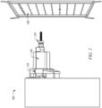
- FIGURE 1 illustrates a temporary fastener actuation system 100, according to certain embodiments.
- Temporary fastener actuation system 100 included a rotary tool 110, a temporary fastener actuation tool 120, and a temporary fastener 130.
- temporary fastener actuation tool 120 is coupled to or otherwise manipulated by rotary tool 110.
- a temporary fastener 130 is inserted into temporary fastener actuation tool 120 and then tines of temporary fastener 130 (i.e., tines 306) are inserted through aligned holes in panels 140.
- Rotary tool 110 then rotates a shaft (i.e., motor shaft 121) within temporary fastener actuation tool 120 which in turn rotates a stem (i.e., stem 302) of temporary fastener 130.
- a shaft i.e., motor shaft 121
- stem i.e., stem 302
- Rotary tool 110 may also rotate motor shaft 121 within temporary fastener actuation tool 120 in an opposite direction in order retract the tines of temporary fastener 130 and loosen temporary fastener 130 from panels 140.
- Rotary tool 110 is any appropriate tool or device capable of operating temporary fastener 130 as described herein.
- rotary tool 110 is a multi-function end effector (MFEE) or a three-axis robotic system (e.g., from Kuka Aerospace).
- MFEE multi-function end effector
- rotary tool 110 holds or otherwise attaches to temporary fastener actuation tool 120, positions and aligns temporary fastener actuation tool 120 with holes in panel 140, and spins motor shaft 121 within temporary fastener actuation tool 120 in order to actuate temporary fastener 130 as described herein.
- rotary tool 110 may be configured to rotate motor shaft 121 and inner bearing 126 in a first direction while outer bearing 125 is stationary, thereby causing the tines of temporary fastener 130 to expand.
- rotary tool 110 may rotate motor shaft 121 in a second direction (opposite from the first direction) while outer bearing 125 is stationary, thereby causing the tines of temporary fastener 130 to contract.
- rotary tool 110 may be configured to rotate motor shaft 121 and the outer bearing 125 in the first direction while the inner bearing 126 is disengaged from the stem 302, thereby causing the entire body of the temporary fastener 130 to rotate.
- FIGURES 2A and 2B illustrate a temporary fastener actuation tool 120, according to certain embodiments.
- temporary fastener actuation tool 120 is generally cylindrical in shape as illustrated. This may allow temporary fastener actuation tool 120 to be at least partially inserted into a tool receptacle of rotary tool 110 and coupled to rotary tool 110.
- temporary fastener actuation tool 120 includes a motor shaft 121, a protrusion 122, one or more spring clips 124 (e.g., 124a and 124b), an outer bearing 125, an inner bearing 126, a bearing shaft 127, a spindle 128, and threads 129.
- Motor shaft 121 is coupled to bearing shaft 127.
- Both motor shaft 121 and bearing shaft 127 are configured to rotate within temporary fastener actuation tool 120 about an axis 210.
- motor shaft 121 includes spindle 128 coupled to one end of motor shaft 121 as illustrated.
- bearing shaft 127 includes threads 129 which couple bearing shaft 127 to spindle 128.
- Motor shaft 121 in general, transfers rotational power from rotary tool 110 to bearing shaft 127 in order to rotate inner bearing 126. This rotates stem 302 of temporary fastener 130, thereby actuating temporary fastener 130.
- Protrusion 122 is coupled to an end 220 of temporary fastener 130 as illustrated.
- protrusion 122 assists in holding temporary fastener 130 within temporary fastener actuation tool 120.
- protrusion 122 includes a groove 230 that matches a cross-sectional shape of indentation 301 of temporary fastener 130.
- groove 230 is circular in shape as illustrated. This allows indentation 301 of temporary fastener 130 to be held firmly in place against protrusion 122 (i.e., indentation 301 rests against groove 230 while a portion of body 300 rests against inside portion 260 of protrusion 122).
- temporary fastener 130 include one or more spring clips 124.
- Spring clips 124 are coupled to end 220 of temporary fastener 130 as illustrated.
- Each spring clip 124 includes an end 240 that is aligned with an end 250 of protrusion 122.
- Spring clips 124 may be made of metal, plastic, or any other appropriate material that allows spring clips 124 to be flexible and spring-loaded.
- outer bearing 125 is configured to contact body 300 of temporary fastener 130 and hold body 300 of temporary fastener 130 stationary during actuation of temporary fastener 130.
- outer bearing 125 may have an inside diameter that permits outer bearing 125 to contact and hold body 300 stationary.
- outer bearing 125 is configured to contact body 300 of temporary fastener 130 and rotate body 300 during actuation of temporary fastener 130.
- outer bearing 125 may have an inside diameter that permits outer bearing 125 to contact and rotate body 300.
- outer bearing 125 is located proximate to end 220 of temporary fastener actuation tool 120 as illustrated. In some embodiments, outer bearing 125 is tubular in shape such that at least a portion of temporary fastener 130 may be inserted through outer bearing 125.
- Inner bearing 126 is configured to contact stem 302 of temporary fastener 130 and rotate stem 302 during actuation of temporary fastener 130.
- inner bearing 126 is located proximate to outer bearing 125 as illustrated.
- inner bearing 126 is tubular in shape such that at least a portion of temporary fastener 130 (e.g., stem 302) may be inserted through inner bearing 126.
- inner bearing 126 has an inside diameter that permits inner bearing 126 to contact and rotate stem 302.
- collar 170 serves to press fit over a body 300 of temporary fastener 130 to hold body 300 stationary while actuating stem 302 of temporary fastener 130 via inner bearing 126. In some embodiments, collar 170 permits body 300 of temporary fastener 130 to rotate while actuating stem 302 of temporary fastener 130 via outer bearing 125. Collar 170 may be located proximate to end 220 of temporary fastener actuation tool 120 as illustrated. In some embodiments, collar 170 is tubular in shape. Collar 170 may be made of any suitable material (e.g., plastic).
- Temporary fastener 130 is any appropriate fastener for holding panels 140 together.
- temporary fastener 130 is a Cleco fastener. A particular embodiment of temporary fastener 130 is described in more detail below with respect to FIGURE 3 .
- Panels 140 are materials or objects to be held together during manufacturing.
- panels 140 are panels of an aircraft.
- panels 140 are panels of an automobile.
- panels 140 have holes that align and permit temporary fastener 130 to be inserted into for holding panels 140 together.
- FIGURE 3 illustrates a temporary fastener 130, according to certain embodiments.
- Temporary fastener 130 may be any suitable size, height, shape, and any combinations thereof.
- temporary fastener 130 may include any suitable materials, including, but not limited to, metals, nonmetals, polymers, ceramics, composites, and any combinations thereof. Without limitations, temporary fastener 130 may be any suitable fastener. In some embodiments, temporary fastener 130 is a Cleco fastener.
- temporary fastener 130 may include a body 300, an indentation 301, a stem 302, a spreader bar 304, a pair of tines 306a and 306b, a pair of barbs 308a and 308b, and a compressible gasket 412.
- Body 300 and indentation 301 may be generally cylindrical in shape, with indentation 301 having a smaller diameter than portions of body 300 on each end of indentation 301 as illustrated.
- Body 300 may be configured to contain at least a portion of stem 302, and stem 302 may be configured to translate in a reversible direction with respect to body 300.
- stem 302 may be disposed within and secured to body 300.
- stem 302 may be threaded into and with the interior of body 300. During operations, a top portion 312 of stem 302 extending out from body 300 may be rotated to translate the stem 302 along a central axis of body 300.
- spreader bar 304 may be coupled to an end of body 300 opposite from top portion 312. As illustrated, spreader bar 304 may extend outwards from body 300, and tines 306 may be disposed adjacent to spreader bar 304. A first tine 306a may be disposed along one side of spreader bar 304, and a second tine 306b may be disposed along an opposing side of spreader bar 304. Tines 306 may each be coupled to stem 302. As stem 302 is actuated to rotate, spreader bar 304 may remain stationary and tines 306 may translate along with stem 302. In one or more embodiments, tines 306 retract backwards into body 300 and spreader bar 304 may be configured to force tines 306 to expand outwards in a radial direction.
- tines 306 extend outwards from body 300 and a distance between tines 306 may decrease in the radial direction.
- barbs 308 may be disposed at a distal end of tines 306.
- a first barb 308a may be disposed at a distal end 314 of first tine 306a
- a second barb 308b may be disposed at a distal end 316 of second tine 306b.
- barbs 308 may translate, expand, and retract subsequently as tines 306 are actuated.
- FIGURES 4A and 4B illustrate temporary fastener 130 coupling separate panels of material together.
- temporary fastener 130 may be at least partially inserted through a hole in a first panel 400 of material and a second panel 402 of material.
- First panel 400 of material and second panel 402 of material may each be any suitable size, height, shape, and any combinations thereof.
- first panel 400 of material and second panel 402 of material may each include any suitable materials, including, but not limited to, metals, nonmetals, polymers, ceramics, composites, and any combinations thereof.
- tines 306 and barbs 308 may be inserted through a first side 404 of first panel 400 and exit out a second side 410 of second panel 402, wherein a second side 406 of first panel 400 is disposed against a first side 408 of second panel 402.
- stem 302 (referring to FIG. 3 ) of the temporary fastener 130 may be rotated to retract tines 306.
- spreader bar 304 (referring to FIG. 3 ) may cause tines 306 and subsequently barbs 308 to expand in a radial direction.
- Barbs 308 may be expanded past the size of the hole of panels 400 and 402 and come to rest against second side 410 of second panel 402.
- Temporary fastener 130 may then be further actuated and may cause barbs 308 to exert a force backwards against second panel 402.
- compressible gasket 412 may be disposed at an end of body 300 (referring to FIG. 3 ) that is operable to provide protection for body 300 and/or for first panel 400.
- a compressive force may be applied onto both first panel 400 and second panel 402 between gasket 412 and barbs 308, thereby temporarily securing first panel 400 to second panel 402.
- the disclosed embodiments provide a temporary fastener actuation system 100 that utilizes a temporary fastener actuation tool 120 to automatically actuate a temporary fastener 130.
- a temporary fastener actuation tool 120 is first coupled or otherwise installed onto rotary tool 110.
- temporary fastener actuation tool 120 is manipulated (either manually or automatically by rotary tool 110) so that axis 210 is aligned with the installed temporary fastener 130.
- Temporary fastener actuation tool 120 is then moved so that temporary fastener 130 is forced into temporary fastener 130.
- spring clips 124 and protrusion 122 aligns with and contacts indentation 301, thereby securing temporary fastener 130 within temporary fastener actuation tool 120.
- Body 300 contacts outer bearing 125, and stem 302 contacts inner bearing 126 within temporary fastener 130.
- Motor shaft 121 is then rotated by rotary tool 110, which in turn rotates bearing shaft 127, inner bearing 126, and ultimately stem 302. Since outer bearing 125 prevents body 300 of temporary fastener 130 from rotating while stem 302 is rotated by inner bearing 126, temporary fastener 130 is actuated to contract tines 306. This loosens and frees temporary fastener 130 from panel 140. Temporary fastener actuation tool 120 is then retracted away from panel 140, which pulls temporary fastener 130 free from panel 140.
- temporary fastener 130 may first be inserted into temporary fastener actuation tool 120. When inserted into temporary fastener 130, spring clips 124 and protrusion 122 aligns with and contacts indentation 301, thereby securing temporary fastener 130 within temporary fastener actuation tool 120. Body 300 contacts outer bearing and stem 302 contacts inner bearing 126. Motor shaft 121 is then rotated by rotary tool 110 in an opposite direct than above, which in turn rotates bearing shaft 127, inner bearing 126, and ultimately stem 302. Since outer bearing 125 prevents body 300 of temporary fastener 130 from rotating while stem 302 is rotated by inner bearing 126, temporary fastener 130 is actuated to expand tines 306. This secures temporary fastener 130 onto panel 140.
- outer bearing 125 of temporary fastener actuation tool 120 contacts body 300 of the temporary fastener 130 and rotates body 300 of temporary fastener 130.
- Collar 170 is configured to contact body 300 of temporary fastener 130 and hold body 300 of temporary fastener 130 stationary when stem 302 is rotated in the opposite direction.
- references in the appended claims to an apparatus or system or a component of an apparatus or system being adapted to, arranged to, capable of, configured to, enabled to, operable to, or operative to perform a particular function encompasses that apparatus, system, component, whether or not it or that particular function is activated, turned on, or unlocked, as long as that apparatus, system, or component is so adapted, arranged, capable, configured, enabled, operable, or operative. Additionally, although this disclosure describes or illustrates particular embodiments as providing particular advantages, particular embodiments may provide none, some, or all of these advantages.
- any subject matter resulting from a deliberate reference back to any previous claims can be claimed as well, so that any combination of claims and the features thereof are disclosed and can be claimed regardless of the dependencies chosen in the attached claims.
- the subject-matter which can be claimed comprises not only the combinations of features as set out in the attached claims but also any other combination of features in the claims, wherein each feature mentioned in the claims can be combined with any other feature or combination of other features in the claims.
- any of the embodiments and features described or depicted herein can be claimed in a separate claim and/or in any combination with any embodiment or feature described or depicted herein or with any of the features of the attached claims.
- each refers to each member of a set or each member of a subset of a set.
- or is not necessarily exclusive and, unless expressly indicated otherwise, can be inclusive in certain embodiments and can be understood to mean “and/or.”
- and is not necessarily inclusive and, unless expressly indicated otherwise, can be inclusive in certain embodiments and can be understood to mean “and/or.” All references to "a/an/the element, apparatus, component, means, step, etc.” are to be interpreted openly as referring to at least one instance of the element, apparatus, component, means, step, etc., unless explicitly stated otherwise.
Landscapes
- Engineering & Computer Science (AREA)
- Mechanical Engineering (AREA)
- General Engineering & Computer Science (AREA)
- Insertion Pins And Rivets (AREA)
- Hand Tools For Fitting Together And Separating, Or Other Hand Tools (AREA)
Abstract
Description
- This disclosure relates in general to temporary fasteners, and more particularly to an automated temporary fastener actuation apparatus and system.
- Temporary fasteners, such as Cleco fasteners, are used in manufacturing processes to fasten different materials together during the manufacturing process. As the materials are held together, personnel may perform other processes to physically join the materials. Afterwards, the temporary fasteners are removed from the joined materials for further assembly operations. Current processes to apply and remove temporary fasteners are manual and time-consuming.
- According to one embodiment, a temporary fastener actuation system includes a temporary fastener, a temporary fastener actuation tool, a rotary tool, and a collar. The temporary fastener includes a cylindrical body having an indentation, a compressible gasket, a stem, and a plurality of tines coupled to the stem. The temporary fastener actuation tool includes a protrusion having a groove that matches a shape of the indentation of the temporary fastener. The temporary fastener actuation tool further includes a plurality of spring clips, wherein each spring clip includes an end that is aligned with an end of the protrusion. The spring clips are configured to hold the indentation of the temporary fastener secure against the protrusion. The temporary fastener actuation tool further includes a bearing shaft, a first bearing coupled to the bearing shaft and configured to contact the cylindrical body of the temporary fastener and rotate the cylindrical body of the temporary fastener in a first direction, a second bearing coupled to the bearing shaft and configured to contact the stem of the temporary fastener and rotate the stem of the temporary fastener in the second direction, and a motor shaft coupled to the bearing shaft. The rotary tool is configured to couple to the motor shaft of the fastener removal tool; rotate the motor shaft and the second bearing in the second direction while the first bearing is disengaged from the cylindrical body, thereby causing the plurality of tines to contract; and rotate the motor shaft and the first bearing in the first direction while the second bearing is disengaged from the stem, thereby causing the cylindrical body of the temporary fastener to rotate. The collar is configured to contact the cylindrical body of the temporary fastener and hold the cylindrical body of the temporary fastener stationary when the stem is rotated in the second direction.
- According to another embodiment, a temporary fastener actuation system includes a temporary fastener actuation tool, a rotary tool, and a collar. The temporary fastener actuation tool includes a protrusion having a groove that matches a shape of an indentation of a temporary fastener. The temporary fastener actuation tool further includes a plurality of spring clips, each spring clip having an end that is aligned with an end of the protrusion. The spring clips are configured to hold the indentation of the temporary fastener secure against the protrusion. The temporary fastener actuation tool further include a bearing shaft, a first bearing coupled to the bearing shaft and configured to contact a cylindrical body of the temporary fastener and rotate the cylindrical body of the temporary fastener in the first direction, a second bearing coupled to the bearing shaft and configured to contact the stem of the temporary fastener and rotate the stem of the temporary fastener in the second direction, and a motor shaft coupled to the bearing shaft. The rotary tool is configured to couple to the motor shaft of the fastener removal tool; rotate the motor shaft and the second bearing in the second direction while the first bearing is disengaged from the cylindrical body, thereby causing a plurality of tines of the temporary fastener to contract; and rotate the motor shaft and the first bearing in the first direction while the second bearing is disengaged from the stem, thereby causing the cylindrical body of the temporary fastener to rotate. The collar is configured to contact the cylindrical body of the temporary fastener and hold the cylindrical body of the temporary fastener stationary when the stem is rotated in the second direction.
- According to another embodiment, a temporary fastener actuation tool includes a protrusion, multiple spring clips, and a bearing shaft. The protrusion includes a groove that matches a shape of an indentation of a temporary fastener. Each spring clip includes an end that is aligned with an end of the protrusion. The spring clips are configured to hold the indentation of the temporary fastener secure against the protrusion. The temporary fastener actuation tool further includes a first bearing coupled to the bearing shaft and configured to contact a cylindrical body of the temporary fastener and rotate the cylindrical body of the temporary fastener in a first direction. The temporary fastener actuation tool further includes a second bearing coupled to the bearing shaft and configured to contact the stem of the temporary fastener and rotate the stem of the temporary fastener in a second direction. The temporary fastener actuation tool further includes a motor shaft coupled to the bearing shaft.
- Technical advantages of certain embodiments may include providing an automated temporary fastener actuation apparatus and system. Instead of the typical manual processes currently used to apply and remove temporary fasteners such as Cleco fasteners, the disclosed embodiments quickly and automatically actuate temporary fasteners, thereby saving considerable time and expenses. Other technical advantages will be readily apparent to one skilled in the art from the following figures, descriptions, and claims. Moreover, while specific advantages have been enumerated above, various embodiments may include all, some, or none of the enumerated advantages.
- For a more complete understanding of the present disclosure and its advantages, reference is now made to the following description, taken in conjunction with the accompanying drawings, in which:
-
FIGURE 1 illustrates an automated temporary fastener actuation system, according to certain embodiments; -
FIGURES 2A and2B illustrate an automated temporary fastener actuation tool, according to certain embodiments; -
FIGURE 3 illustrates a temporary fastener, according to certain embodiments; and -
FIGURES 4A and 4B illustrates the temporary fastener ofFIGURE 3 coupling panels of material together, according to certain embodiments. - Temporary fasteners, such as Cleco fasteners, are used in manufacturing processes to fasten different materials together during the manufacturing process. As the materials are held together, personnel may perform other processes to physically join the materials. Afterwards, the temporary fasteners are removed from the joined materials for further assembly operations. Current processes to apply and remove temporary fasteners are manual and time-consuming.
- To address these and other problems with manually actuating temporary fasteners such as Cleco fasteners, the disclosed embodiments provide an automated temporary fastener actuation tool and system. Instead of the typical manual processes currently used to apply and remove temporary fasteners such as Cleco fasteners, the disclosed embodiments quickly and automatically actuate temporary fasteners, thereby saving considerable time and expenses. To do so, some embodiments utilize a rotary tool such as a multi-function end effector (MFEE) and a temporary fastener actuation tool to actuate a temporary fastener such as a Cleco fastener. The rotary tool rotates a shaft within the temporary fastener actuation tool which in turn automatically actuates the temporary fastener to either remove or apply the temporary fastener to a panel. As a result, a temporary fastener such as a Cleco fastener may be automatically actuated without requiring manual operation by personnel.
- To facilitate a better understanding of the present disclosure, the following examples of certain embodiments are given. In no way should the following examples be read to limit or define the scope of the disclosure. Embodiments of the present disclosure and its advantages may be best understood by referring to the included FIGURES, where like numbers are used to indicate like and corresponding parts.
-
FIGURE 1 illustrates a temporaryfastener actuation system 100, according to certain embodiments. Temporaryfastener actuation system 100 included arotary tool 110, a temporaryfastener actuation tool 120, and atemporary fastener 130. In general, temporaryfastener actuation tool 120 is coupled to or otherwise manipulated byrotary tool 110. Atemporary fastener 130 is inserted into temporaryfastener actuation tool 120 and then tines of temporary fastener 130 (i.e., tines 306) are inserted through aligned holes inpanels 140.Rotary tool 110 then rotates a shaft (i.e., motor shaft 121) within temporaryfastener actuation tool 120 which in turn rotates a stem (i.e., stem 302) oftemporary fastener 130. This actuates the tines oftemporary fastener 130 and temporarily securestemporary fastener 130 topanels 140, thereby securingpanels 140 together for manufacturing purposes.Rotary tool 110 may also rotatemotor shaft 121 within temporaryfastener actuation tool 120 in an opposite direction in order retract the tines oftemporary fastener 130 and loosentemporary fastener 130 frompanels 140. -
Rotary tool 110 is any appropriate tool or device capable of operatingtemporary fastener 130 as described herein. In some embodiments,rotary tool 110 is a multi-function end effector (MFEE) or a three-axis robotic system (e.g., from Kuka Aerospace). In general,rotary tool 110 holds or otherwise attaches to temporaryfastener actuation tool 120, positions and aligns temporaryfastener actuation tool 120 with holes inpanel 140, and spinsmotor shaft 121 within temporaryfastener actuation tool 120 in order to actuatetemporary fastener 130 as described herein. For example,rotary tool 110 may be configured to rotatemotor shaft 121 andinner bearing 126 in a first direction whileouter bearing 125 is stationary, thereby causing the tines oftemporary fastener 130 to expand. As another example,rotary tool 110 may rotatemotor shaft 121 in a second direction (opposite from the first direction) whileouter bearing 125 is stationary, thereby causing the tines oftemporary fastener 130 to contract. As still another example,rotary tool 110 may be configured to rotatemotor shaft 121 and theouter bearing 125 in the first direction while theinner bearing 126 is disengaged from thestem 302, thereby causing the entire body of thetemporary fastener 130 to rotate. -
FIGURES 2A and2B illustrate a temporaryfastener actuation tool 120, according to certain embodiments. In some embodiments, temporaryfastener actuation tool 120 is generally cylindrical in shape as illustrated. This may allow temporaryfastener actuation tool 120 to be at least partially inserted into a tool receptacle ofrotary tool 110 and coupled torotary tool 110. In some embodiments, temporaryfastener actuation tool 120 includes amotor shaft 121, aprotrusion 122, one or more spring clips 124 (e.g., 124a and 124b), anouter bearing 125, aninner bearing 126, a bearingshaft 127, aspindle 128, andthreads 129.Motor shaft 121 is coupled to bearingshaft 127. Bothmotor shaft 121 and bearingshaft 127 are configured to rotate within temporaryfastener actuation tool 120 about anaxis 210. In some embodiments,motor shaft 121 includesspindle 128 coupled to one end ofmotor shaft 121 as illustrated. In such embodiments, bearingshaft 127 includesthreads 129 whichcouple bearing shaft 127 tospindle 128.Motor shaft 121, in general, transfers rotational power fromrotary tool 110 to bearingshaft 127 in order to rotateinner bearing 126. This rotatesstem 302 oftemporary fastener 130, thereby actuatingtemporary fastener 130. -
Protrusion 122 is coupled to anend 220 oftemporary fastener 130 as illustrated. In general,protrusion 122 assists in holdingtemporary fastener 130 within temporaryfastener actuation tool 120. In some embodiments,protrusion 122 includes agroove 230 that matches a cross-sectional shape ofindentation 301 oftemporary fastener 130. For example, ifbody 300 andindentation 301 are cylindrical in shape as illustrated,groove 230 is circular in shape as illustrated. This allowsindentation 301 oftemporary fastener 130 to be held firmly in place against protrusion 122 (i.e.,indentation 301 rests againstgroove 230 while a portion ofbody 300 rests againstinside portion 260 of protrusion 122). To help holdtemporary fastener 130 againstprotrusion 122, some embodiments oftemporary fastener 130 include one or more spring clips 124. Spring clips 124 are coupled to end 220 oftemporary fastener 130 as illustrated. Eachspring clip 124 includes anend 240 that is aligned with anend 250 ofprotrusion 122. Spring clips 124 may be made of metal, plastic, or any other appropriate material that allows spring clips 124 to be flexible and spring-loaded. - In certain embodiments,
outer bearing 125 is configured to contactbody 300 oftemporary fastener 130 and holdbody 300 oftemporary fastener 130 stationary during actuation oftemporary fastener 130. For example,outer bearing 125 may have an inside diameter that permitsouter bearing 125 to contact and holdbody 300 stationary. - In some embodiments,
outer bearing 125 is configured to contactbody 300 oftemporary fastener 130 and rotatebody 300 during actuation oftemporary fastener 130. For example,outer bearing 125 may have an inside diameter that permitsouter bearing 125 to contact and rotatebody 300. - In certain embodiments,
outer bearing 125 is located proximate to end 220 of temporaryfastener actuation tool 120 as illustrated. In some embodiments,outer bearing 125 is tubular in shape such that at least a portion oftemporary fastener 130 may be inserted throughouter bearing 125. -
Inner bearing 126 is configured to contactstem 302 oftemporary fastener 130 and rotatestem 302 during actuation oftemporary fastener 130. In some embodiments,inner bearing 126 is located proximate toouter bearing 125 as illustrated. In some embodiments,inner bearing 126 is tubular in shape such that at least a portion of temporary fastener 130 (e.g., stem 302) may be inserted throughinner bearing 126. In general,inner bearing 126 has an inside diameter that permitsinner bearing 126 to contact and rotatestem 302. - In certain embodiments,
collar 170 serves to press fit over abody 300 oftemporary fastener 130 to holdbody 300 stationary while actuating stem 302 oftemporary fastener 130 viainner bearing 126. In some embodiments,collar 170permits body 300 oftemporary fastener 130 to rotate while actuating stem 302 oftemporary fastener 130 viaouter bearing 125.Collar 170 may be located proximate to end 220 of temporaryfastener actuation tool 120 as illustrated. In some embodiments,collar 170 is tubular in shape.Collar 170 may be made of any suitable material (e.g., plastic). -
Temporary fastener 130 is any appropriate fastener for holdingpanels 140 together. In some embodiments,temporary fastener 130 is a Cleco fastener. A particular embodiment oftemporary fastener 130 is described in more detail below with respect toFIGURE 3 . -
Panels 140 are materials or objects to be held together during manufacturing. In some embodiments, for example,panels 140 are panels of an aircraft. As another example,panels 140 are panels of an automobile. In general,panels 140 have holes that align and permittemporary fastener 130 to be inserted into for holdingpanels 140 together. -
FIGURE 3 illustrates atemporary fastener 130, according to certain embodiments.Temporary fastener 130 may be any suitable size, height, shape, and any combinations thereof. In some embodiments,temporary fastener 130 may include any suitable materials, including, but not limited to, metals, nonmetals, polymers, ceramics, composites, and any combinations thereof. Without limitations,temporary fastener 130 may be any suitable fastener. In some embodiments,temporary fastener 130 is a Cleco fastener. - In some embodiments,
temporary fastener 130 may include abody 300, anindentation 301, astem 302, aspreader bar 304, a pair oftines barbs compressible gasket 412.Body 300 andindentation 301 may be generally cylindrical in shape, withindentation 301 having a smaller diameter than portions ofbody 300 on each end ofindentation 301 as illustrated.Body 300 may be configured to contain at least a portion ofstem 302, and stem 302 may be configured to translate in a reversible direction with respect tobody 300. For example, stem 302 may be disposed within and secured tobody 300. In one or more embodiments, stem 302 may be threaded into and with the interior ofbody 300. During operations, atop portion 312 ofstem 302 extending out frombody 300 may be rotated to translate thestem 302 along a central axis ofbody 300. - In some embodiments,
spreader bar 304 may be coupled to an end ofbody 300 opposite fromtop portion 312. As illustrated,spreader bar 304 may extend outwards frombody 300, and tines 306 may be disposed adjacent tospreader bar 304. Afirst tine 306a may be disposed along one side ofspreader bar 304, and asecond tine 306b may be disposed along an opposing side ofspreader bar 304. Tines 306 may each be coupled to stem 302. Asstem 302 is actuated to rotate,spreader bar 304 may remain stationary and tines 306 may translate along withstem 302. In one or more embodiments, tines 306 retract backwards intobody 300 andspreader bar 304 may be configured to force tines 306 to expand outwards in a radial direction. In one or more embodiments, tines 306 extend outwards frombody 300 and a distance between tines 306 may decrease in the radial direction. In some embodiments, barbs 308 may be disposed at a distal end of tines 306. Afirst barb 308a may be disposed at adistal end 314 offirst tine 306a, and asecond barb 308b may be disposed at adistal end 316 ofsecond tine 306b. In some embodiments, barbs 308 may translate, expand, and retract subsequently as tines 306 are actuated. -
FIGURES 4A and 4B illustratetemporary fastener 130 coupling separate panels of material together. As illustrated,temporary fastener 130 may be at least partially inserted through a hole in afirst panel 400 of material and asecond panel 402 of material.First panel 400 of material andsecond panel 402 of material may each be any suitable size, height, shape, and any combinations thereof. In some embodiments,first panel 400 of material andsecond panel 402 of material may each include any suitable materials, including, but not limited to, metals, nonmetals, polymers, ceramics, composites, and any combinations thereof. In some embodiments, tines 306 and barbs 308 may be inserted through afirst side 404 offirst panel 400 and exit out asecond side 410 ofsecond panel 402, wherein asecond side 406 offirst panel 400 is disposed against afirst side 408 ofsecond panel 402. To exert a force and clamppanels FIG. 3 ) of thetemporary fastener 130 may be rotated to retract tines 306. As tines 306 retract, spreader bar 304 (referring toFIG. 3 ) may cause tines 306 and subsequently barbs 308 to expand in a radial direction. Barbs 308 may be expanded past the size of the hole ofpanels second side 410 ofsecond panel 402.Temporary fastener 130 may then be further actuated and may cause barbs 308 to exert a force backwards againstsecond panel 402. As illustrated,compressible gasket 412 may be disposed at an end of body 300 (referring toFIG. 3 ) that is operable to provide protection forbody 300 and/or forfirst panel 400. A compressive force may be applied onto bothfirst panel 400 andsecond panel 402 betweengasket 412 and barbs 308, thereby temporarily securingfirst panel 400 tosecond panel 402. - In operation, and in reference to
FIGURES 1-4B , the disclosed embodiments provide a temporaryfastener actuation system 100 that utilizes a temporaryfastener actuation tool 120 to automatically actuate atemporary fastener 130. Instead of the typical manual processes currently used to apply and removetemporary fasteners 130 such as Cleco fasteners, the disclosed embodiments quickly and automatically actuatetemporary fasteners 130, thereby saving considerable time and expenses. To do so, temporaryfastener actuation tool 120 is first coupled or otherwise installed ontorotary tool 110. Next, iftemporary fastener 130 is already installed intopanel 140, temporaryfastener actuation tool 120 is manipulated (either manually or automatically by rotary tool 110) so thataxis 210 is aligned with the installedtemporary fastener 130. Temporaryfastener actuation tool 120 is then moved so thattemporary fastener 130 is forced intotemporary fastener 130. When inserted intotemporary fastener 130, spring clips 124 andprotrusion 122 aligns with and contacts indentation 301, thereby securingtemporary fastener 130 within temporaryfastener actuation tool 120.Body 300 contactsouter bearing 125, and stem 302 contactsinner bearing 126 withintemporary fastener 130.Motor shaft 121 is then rotated byrotary tool 110, which in turn rotates bearingshaft 127,inner bearing 126, and ultimately stem 302. Sinceouter bearing 125 preventsbody 300 oftemporary fastener 130 from rotating whilestem 302 is rotated byinner bearing 126,temporary fastener 130 is actuated to contract tines 306. This loosens and freestemporary fastener 130 frompanel 140. Temporaryfastener actuation tool 120 is then retracted away frompanel 140, which pullstemporary fastener 130 free frompanel 140. - If temporary
fastener actuation system 100 is used to installtemporary fastener 130 intopanel 140,temporary fastener 130 may first be inserted into temporaryfastener actuation tool 120. When inserted intotemporary fastener 130, spring clips 124 andprotrusion 122 aligns with and contacts indentation 301, thereby securingtemporary fastener 130 within temporaryfastener actuation tool 120.Body 300 contacts outer bearing and stem 302 contactsinner bearing 126.Motor shaft 121 is then rotated byrotary tool 110 in an opposite direct than above, which in turn rotates bearingshaft 127,inner bearing 126, and ultimately stem 302. Sinceouter bearing 125 preventsbody 300 oftemporary fastener 130 from rotating whilestem 302 is rotated byinner bearing 126,temporary fastener 130 is actuated to expand tines 306. This securestemporary fastener 130 ontopanel 140. - If temporary
fastener actuation system 100 is used to breaktemporary fastener 130 loose from sealant that may have cured totemporary fastener 130,outer bearing 125 of temporaryfastener actuation tool 120contacts body 300 of thetemporary fastener 130 and rotatesbody 300 oftemporary fastener 130.Collar 170 is configured to contactbody 300 oftemporary fastener 130 and holdbody 300 oftemporary fastener 130 stationary whenstem 302 is rotated in the opposite direction. - Herein, "or" is inclusive and not exclusive, unless expressly indicated otherwise or indicated otherwise by context. Therefore, herein, "A or B" means "A, B, or both," unless expressly indicated otherwise or indicated otherwise by context. Moreover, "and" is both joint and several, unless expressly indicated otherwise or indicated otherwise by context. Therefore, herein, "A and B" means "A and B, jointly or severally," unless expressly indicated otherwise or indicated otherwise by context.
- The scope of this disclosure encompasses all changes, substitutions, variations, alterations, and modifications to the example embodiments described or illustrated herein that a person having ordinary skill in the art would comprehend. The scope of this disclosure is not limited to the example embodiments described or illustrated herein. Moreover, although this disclosure describes and illustrates respective embodiments herein as including particular components, elements, feature, functions, operations, or steps, any of these embodiments may include any combination or permutation of any of the components, elements, features, functions, operations, or steps described or illustrated anywhere herein that a person having ordinary skill in the art would comprehend. Furthermore, reference in the appended claims to an apparatus or system or a component of an apparatus or system being adapted to, arranged to, capable of, configured to, enabled to, operable to, or operative to perform a particular function encompasses that apparatus, system, component, whether or not it or that particular function is activated, turned on, or unlocked, as long as that apparatus, system, or component is so adapted, arranged, capable, configured, enabled, operable, or operative. Additionally, although this disclosure describes or illustrates particular embodiments as providing particular advantages, particular embodiments may provide none, some, or all of these advantages.
- The embodiments disclosed herein are only examples, and the scope of this disclosure is not limited to them. Particular embodiments may include all, some, or none of the components, elements, features, functions, operations, or steps of the embodiments disclosed herein. Certain embodiments are in particular disclosed in the attached claims directed to a method, a storage medium, a system and a computer program product, wherein any feature mentioned in one claim category, e.g. method, can be claimed in another claim category, e.g. system, as well. The dependencies or references back in the attached claims are chosen for formal reasons only. However, any subject matter resulting from a deliberate reference back to any previous claims (in particular multiple dependencies) can be claimed as well, so that any combination of claims and the features thereof are disclosed and can be claimed regardless of the dependencies chosen in the attached claims. The subject-matter which can be claimed comprises not only the combinations of features as set out in the attached claims but also any other combination of features in the claims, wherein each feature mentioned in the claims can be combined with any other feature or combination of other features in the claims. Furthermore, any of the embodiments and features described or depicted herein can be claimed in a separate claim and/or in any combination with any embodiment or feature described or depicted herein or with any of the features of the attached claims.
- As used in this document, "each" refers to each member of a set or each member of a subset of a set. Furthermore, as used in the document "or" is not necessarily exclusive and, unless expressly indicated otherwise, can be inclusive in certain embodiments and can be understood to mean "and/or." Similarly, as used in this document "and" is not necessarily inclusive and, unless expressly indicated otherwise, can be inclusive in certain embodiments and can be understood to mean "and/or." All references to "a/an/the element, apparatus, component, means, step, etc." are to be interpreted openly as referring to at least one instance of the element, apparatus, component, means, step, etc., unless explicitly stated otherwise.
- Although several embodiments have been illustrated and described in detail, it will be recognized that substitutions and alterations are possible without departing from the spirit and scope of the present disclosure, as defined by the appended claims.
Claims (15)
- A temporary fastener actuation system comprising:a temporary fastener comprising:a cylindrical body comprising an indentation;a compressible gasket;a stem; anda plurality of tines coupled to the stem and configured to:expand when the stem is rotated a first direction, thereby securing the temporary fastener to a panel; andcontract when the stem is rotated a second direction, the second directionbeing opposite from the first direction;a temporary fastener actuation tool comprising:a protrusion comprising a groove that matches a shape of the indentation of the temporary fastener;a plurality of spring clips, each spring clip comprising an end that is aligned with an end of the protrusion, the plurality of spring clips configured to hold the indentation of the temporary fastener secure against the protrusion;a bearing shaft;a first bearing coupled to the bearing shaft and configured to contact the cylindrical body of the temporary fastener and rotate the cylindrical body of the temporary fastener in the first direction;a second bearing coupled to the bearing shaft and configured to contact the stem of the temporary fastener and rotate the stem of the temporary fastener in the second direction; anda motor shaft coupled to the bearing shaft;a rotary tool configured to:couple to the motor shaft of the fastener removal tool;rotate the motor shaft and the first bearing in the first direction while the second bearing is disengaged from the stem, thereby causing the cylindrical body of the temporary fastener to rotate; androtate the motor shaft and the second bearing in the second direction while the first bearing is disengaged from the cylindrical body, thereby causing the plurality of tines to contract; anda collar configured to contact the cylindrical body of the temporary fastener and hold the cylindrical body of the temporary fastener stationary when the stem is rotated in the second direction.
- The temporary fastener actuation system of Claim 1, wherein the temporary fastener is a Cleco fastener.
- The temporary fastener actuation system of Claim 1 or Claim 2, wherein the rotary tool is a multi-function end effector (MFEE); and optionally or preferably
wherein the temporary fastener actuation tool is coupled to the MFEE. - The temporary fastener actuation system of any preceding Claim, wherein:the temporary fastener actuation tool further comprises a spindle coupled to the motor shaft; andthe bearing shaft comprises a threaded end that couples the bearing shaft to the spindle.
- The temporary fastener actuation system of any preceding Claim, wherein the temporary fastener actuation tool is cylindrical in shape; and optionally or preferably
wherein:the protrusion and the plurality of spring clips are coupled to a first end of the temporary fastener actuation tool;
the first bearing is located proximate to the first end of the temporary fastener actuation tool;the second bearing is located proximate to the first bearing; andthe first bearing and the second bearing are both tubular in shape such that at least a portion of the temporary fastener may be inserted through the first bearing and the second bearing. - A temporary fastener actuation system comprising:a temporary fastener actuation tool comprising:a protrusion comprising a groove that matches a shape of an indentation of a temporary fastener;a plurality of spring clips, each spring clip comprising an end that is aligned with an end of the protrusion, the plurality of spring clips configured to hold the indentation of the temporary fastener secure against the protrusion;a bearing shaft;a first bearing coupled to the bearing shaft and configured to contact a cylindrical body of the temporary fastener and rotate the cylindrical body of the temporary fastener in the first direction;a second bearing coupled to the bearing shaft and configured to contact the stem of the temporary fastener and rotate the stem of the temporary fastener in the second direction; anda motor shaft coupled to the bearing shaft;a rotary tool configured to:couple to the motor shaft of the fastener removal tool;rotate the motor shaft and the first bearing in the first direction while the second bearing is disengaged from the stem, thereby causing the cylindrical body of the temporary fastener to rotate; androtate the motor shaft and the second bearing in the second direction while the first bearing is disengaged from the cylindrical body, thereby causing the plurality of tines to contract; anda collar configured to contact a cylindrical body of the temporary fastener and hold the cylindrical body of the temporary fastener stationary when the stem is rotated in the second direction.
- The temporary fastener actuation system of Claim 6, wherein the rotary tool is a multi-function end effector (MFEE); and optionally or preferably
wherein the temporary fastener actuation tool is coupled to the MFEE. - The temporary fastener actuation system of Claim 6 or Claim 7, wherein:the temporary fastener actuation tool further comprises a spindle coupled to the motor shaft; andthe bearing shaft comprises a threaded end that couples the bearing shaft to the spindle.
- The temporary fastener actuation system of any of Claims 6 to 8, wherein the temporary fastener actuation tool is cylindrical in shape.
- The temporary fastener actuation system of any of Claims 6 to 9, wherein:the protrusion and the plurality of spring clips are coupled to a first end of the temporary fastener actuation tool;the first bearing is located proximate to the first end of the temporary fastener actuation tool;the second bearing is located proximate to the first bearing; andthe first bearing and the second bearing are both tubular in shape such that at least a portion of the temporary fastener may be inserted through the first bearing and the second bearing.
- A temporary fastener actuation tool comprising:a protrusion comprising a groove that matches a shape of an indentation of a temporary fastener;a plurality of spring clips, each spring clip comprising an end that is aligned with an end of the protrusion, the plurality of spring clips configured to hold the indentation of the temporary fastener secure against the protrusion;a bearing shaft;a first bearing coupled to the bearing shaft and configured to contact a cylindrical body of the temporary fastener and rotate the cylindrical body of the temporary fastener in a first direction;a second bearing coupled to the bearing shaft and configured to contact the stem of the temporary fastener and rotate the stem of the temporary fastener in a second direction; anda motor shaft coupled to the bearing shaft.
- The temporary fastener actuation system of any of Claims 6 to 10, or the temporary fastener actuation tool of Claim 11, wherein the temporary fastener is a Cleco fastener.
- The temporary fastener actuation tool of Claim 11 or Claim 12, wherein the motor shaft of the temporary fastener actuation tool is configured to couple to a rotary tool; and optionally or preferably
wherein the rotary tool is a multi-function end effector (MFEE). - The temporary fastener actuation tool of any of Claims 11 to 13, wherein:the temporary fastener actuation tool further comprises a spindle coupled to the motor shaft; andthe bearing shaft comprises a threaded end that couples the bearing shaft to the spindle.
- The temporary fastener actuation tool of any of Claims 11 to 14, wherein:the protrusion and the plurality of spring clips are coupled to a first end of the temporary fastener actuation tool;the first bearing is located proximate to the first end of the temporary fastener actuation tool;the second bearing is located proximate to the first bearing; andthe first bearing and the second bearing are both tubular in shape such that at least a portion of the temporary fastener may be inserted through the first bearing and the second bearing.
Priority Applications (1)
| Application Number | Priority Date | Filing Date | Title |
|---|---|---|---|
| EP26169666.0A EP4744828A2 (en) | 2023-06-26 | 2024-06-19 | DEVICE AND SYSTEM FOR THE AUTOMATIC TEMPORARY ACTIVATION OF FASTENING ELEMENTS |
Applications Claiming Priority (1)
| Application Number | Priority Date | Filing Date | Title |
|---|---|---|---|
| US18/341,612 US20240424625A1 (en) | 2023-06-26 | 2023-06-26 | Automated Temporary Fastener Actuation Apparatus and System |
Publications (2)
| Publication Number | Publication Date |
|---|---|
| EP4484066A1 true EP4484066A1 (en) | 2025-01-01 |
| EP4484066B1 EP4484066B1 (en) | 2026-05-20 |
Family
ID=91616825
Family Applications (2)
| Application Number | Title | Priority Date | Filing Date |
|---|---|---|---|
| EP24183198.1A Active EP4484066B1 (en) | 2023-06-26 | 2024-06-19 | DEVICE AND SYSTEM FOR THE AUTOMATIC TEMPORARY ACTIVATION OF FASTENING ELEMENTS |
| EP26169666.0A Pending EP4744828A2 (en) | 2023-06-26 | 2024-06-19 | DEVICE AND SYSTEM FOR THE AUTOMATIC TEMPORARY ACTIVATION OF FASTENING ELEMENTS |
Family Applications After (1)
| Application Number | Title | Priority Date | Filing Date |
|---|---|---|---|
| EP26169666.0A Pending EP4744828A2 (en) | 2023-06-26 | 2024-06-19 | DEVICE AND SYSTEM FOR THE AUTOMATIC TEMPORARY ACTIVATION OF FASTENING ELEMENTS |
Country Status (4)
| Country | Link |
|---|---|
| US (1) | US20240424625A1 (en) |
| EP (2) | EP4484066B1 (en) |
| JP (1) | JP2025013211A (en) |
| AU (1) | AU2024204022A1 (en) |
Families Citing this family (1)
| Publication number | Priority date | Publication date | Assignee | Title |
|---|---|---|---|---|
| FR3151514B1 (en) * | 2023-07-28 | 2025-06-27 | Lisi Aerospace | Installation tool for temporary fixing and associated installation kit |
Citations (2)
| Publication number | Priority date | Publication date | Assignee | Title |
|---|---|---|---|---|
| GB2126146A (en) * | 1982-08-23 | 1984-03-21 | Desoutter Ltd | A power tool for inserting and extracting a clamp |
| EP0195851B1 (en) * | 1985-03-29 | 1992-01-29 | MAG Aerospace Industries, Inc. | Installing tool for wedging-type fasteners |
Family Cites Families (5)
| Publication number | Priority date | Publication date | Assignee | Title |
|---|---|---|---|---|
| US2387371A (en) * | 1944-11-03 | 1945-10-23 | Herman H Heibush | Clamp |
| US2775155A (en) * | 1954-04-12 | 1956-12-25 | Monogram Mfg Company | Sheet metal clamp |
| US3263320A (en) * | 1964-04-20 | 1966-08-02 | Monogram Ind Inc | Apparatus and method for assembling and disassembling clamps |
| US4787274A (en) * | 1985-03-29 | 1988-11-29 | Monogram Industries, Inc. | Installing tool for wedging-type fasteners |
| US9687946B2 (en) * | 2014-04-18 | 2017-06-27 | The Boeing Company | Automated apparatus for use in selectively installing temporary fasteners in an assembly |
-
2023
- 2023-06-26 US US18/341,612 patent/US20240424625A1/en active Pending
-
2024
- 2024-06-13 AU AU2024204022A patent/AU2024204022A1/en active Pending
- 2024-06-19 EP EP24183198.1A patent/EP4484066B1/en active Active
- 2024-06-19 EP EP26169666.0A patent/EP4744828A2/en active Pending
- 2024-06-26 JP JP2024103063A patent/JP2025013211A/en active Pending
Patent Citations (2)
| Publication number | Priority date | Publication date | Assignee | Title |
|---|---|---|---|---|
| GB2126146A (en) * | 1982-08-23 | 1984-03-21 | Desoutter Ltd | A power tool for inserting and extracting a clamp |
| EP0195851B1 (en) * | 1985-03-29 | 1992-01-29 | MAG Aerospace Industries, Inc. | Installing tool for wedging-type fasteners |
Also Published As
| Publication number | Publication date |
|---|---|
| EP4484066B1 (en) | 2026-05-20 |
| US20240424625A1 (en) | 2024-12-26 |
| JP2025013211A (en) | 2025-01-24 |
| AU2024204022A1 (en) | 2025-01-16 |
| EP4744828A2 (en) | 2026-05-20 |
Similar Documents
| Publication | Publication Date | Title |
|---|---|---|
| AU2024204022A1 (en) | Automated temporary fastener actuation apparatus and system | |
| US6196779B1 (en) | Temporary fastener with projecting tool-guide bushing | |
| JPS6294208A (en) | Aggregate of step for fixing working unit and working unit proper to cooperate with step | |
| US7156596B2 (en) | Blind rivet and fastening method | |
| WO2000032948A1 (en) | Pin and swage-type fastening system comprising same | |
| EP0198105A1 (en) | Positive-release, wire-pin type clamp for use with automated insertion and withdrawal tool | |
| US20070295781A1 (en) | Tool Assembly Used With Friction Stir Welding | |
| JP2005518509A (en) | Honeycomb rivet | |
| US20240424624A1 (en) | Automated Temporary Fastener Actuation Apparatus and System | |
| US3286335A (en) | Method for replacing a seal in a support housing | |
| US4787274A (en) | Installing tool for wedging-type fasteners | |
| US20060182512A1 (en) | Frangible blind rivet | |
| US11148188B2 (en) | Tool and associated method for installing a blind fastener | |
| US11045863B2 (en) | Apparatus for the removal of a circular collar swage mounted on a cylindrical projection | |
| JP2018126855A (en) | Fastener-installation systems and methods | |
| US5699702A (en) | Wrenching tool with free-floating, self-relieving anti-rotation key | |
| EP0824197B1 (en) | Fastener having spiral shaped collar | |
| US20110197410A1 (en) | Frangible collar removal tool | |
| JP7576930B2 (en) | Fall prevention device | |
| JP2008221324A (en) | Pipe grasping device | |
| EP3242044B1 (en) | Fastening system and method | |
| CN207787778U (en) | Power tool | |
| JP2019014063A (en) | Roof material removal auxiliary tool | |
| JPH02224933A (en) | Tightening device for bolt | |
| JPH04115542U (en) | Fasteners for tightening members |
Legal Events
| Date | Code | Title | Description |
|---|---|---|---|
| PUAI | Public reference made under article 153(3) epc to a published international application that has entered the european phase |
Free format text: ORIGINAL CODE: 0009012 |
|
| STAA | Information on the status of an ep patent application or granted ep patent |
Free format text: STATUS: THE APPLICATION HAS BEEN PUBLISHED |
|
| AK | Designated contracting states |
Kind code of ref document: A1 Designated state(s): AL AT BE BG CH CY CZ DE DK EE ES FI FR GB GR HR HU IE IS IT LI LT LU LV MC ME MK MT NL NO PL PT RO RS SE SI SK SM TR |
|
| STAA | Information on the status of an ep patent application or granted ep patent |
Free format text: STATUS: REQUEST FOR EXAMINATION WAS MADE |
|
| 17P | Request for examination filed |
Effective date: 20250308 |
|
| GRAP | Despatch of communication of intention to grant a patent |
Free format text: ORIGINAL CODE: EPIDOSNIGR1 |
|
| STAA | Information on the status of an ep patent application or granted ep patent |
Free format text: STATUS: GRANT OF PATENT IS INTENDED |
|
| INTG | Intention to grant announced |
Effective date: 20260206 |
|
| GRAS | Grant fee paid |
Free format text: ORIGINAL CODE: EPIDOSNIGR3 |
|
| GRAA | (expected) grant |
Free format text: ORIGINAL CODE: 0009210 |
|
| STAA | Information on the status of an ep patent application or granted ep patent |
Free format text: STATUS: THE PATENT HAS BEEN GRANTED |
|
| P01 | Opt-out of the competence of the unified patent court (upc) registered |
Free format text: CASE NUMBER: UPC_APP_0011267_4484066/2026 Effective date: 20260330 |