EP4484028A1 - Optionally coatable mechanically connected block or abutment for an adjustable drawing die - Google Patents
Optionally coatable mechanically connected block or abutment for an adjustable drawing die Download PDFInfo
- Publication number
- EP4484028A1 EP4484028A1 EP24184499.2A EP24184499A EP4484028A1 EP 4484028 A1 EP4484028 A1 EP 4484028A1 EP 24184499 A EP24184499 A EP 24184499A EP 4484028 A1 EP4484028 A1 EP 4484028A1
- Authority
- EP
- European Patent Office
- Prior art keywords
- block
- insert
- support
- abutment
- steel
- Prior art date
- Legal status (The legal status is an assumption and is not a legal conclusion. Google has not performed a legal analysis and makes no representation as to the accuracy of the status listed.)
- Granted
Links
Images





Classifications
-
- B—PERFORMING OPERATIONS; TRANSPORTING
- B21—MECHANICAL METAL-WORKING WITHOUT ESSENTIALLY REMOVING MATERIAL; PUNCHING METAL
- B21C—MANUFACTURE OF METAL SHEETS, WIRE, RODS, TUBES, PROFILES OR LIKE SEMI-MANUFACTURED PRODUCTS OTHERWISE THAN BY ROLLING; AUXILIARY OPERATIONS USED IN CONNECTION WITH METAL-WORKING WITHOUT ESSENTIALLY REMOVING MATERIAL
- B21C3/00—Profiling tools for metal drawing; Combinations of dies and mandrels for metal drawing
- B21C3/02—Dies; Selection of material therefor; Cleaning thereof
- B21C3/06—Dies; Selection of material therefor; Cleaning thereof with adjustable section
-
- B—PERFORMING OPERATIONS; TRANSPORTING
- B21—MECHANICAL METAL-WORKING WITHOUT ESSENTIALLY REMOVING MATERIAL; PUNCHING METAL
- B21C—MANUFACTURE OF METAL SHEETS, WIRE, RODS, TUBES, PROFILES OR LIKE SEMI-MANUFACTURED PRODUCTS OTHERWISE THAN BY ROLLING; AUXILIARY OPERATIONS USED IN CONNECTION WITH METAL-WORKING WITHOUT ESSENTIALLY REMOVING MATERIAL
- B21C3/00—Profiling tools for metal drawing; Combinations of dies and mandrels for metal drawing
- B21C3/02—Dies; Selection of material therefor; Cleaning thereof
- B21C3/12—Die holders; Rotating dies
-
- B—PERFORMING OPERATIONS; TRANSPORTING
- B21—MECHANICAL METAL-WORKING WITHOUT ESSENTIALLY REMOVING MATERIAL; PUNCHING METAL
- B21C—MANUFACTURE OF METAL SHEETS, WIRE, RODS, TUBES, PROFILES OR LIKE SEMI-MANUFACTURED PRODUCTS OTHERWISE THAN BY ROLLING; AUXILIARY OPERATIONS USED IN CONNECTION WITH METAL-WORKING WITHOUT ESSENTIALLY REMOVING MATERIAL
- B21C3/00—Profiling tools for metal drawing; Combinations of dies and mandrels for metal drawing
- B21C3/18—Making tools by operations not covered by a single other subclass; Repairing
Definitions
- adjustable drawing dies with saddles have the advantage of being more quickly ready, because one of the two dimensions of the drawn product is fixed, and is due to the dimension of the two saddles which, coupled with the abutments, define its thickness.
- adjustable dies with abutments and saddles are less adjustable, because in order to have different drawn product thicknesses it is necessary to mount different pairs of saddles.
- brazed insert solution does not allow coating the block with the CVD technique, because the deposition temperatures required for chemical coatings are significantly higher than the melting temperature of the solder used.
- the dovetail-shaped connection between the cemented carbide insert and the steel support is such that the two opposite longitudinal vertical faces of the insert, and correspondingly the two longitudinal vertical flanks of its housing in the support, are not exactly on two parallel planes. Specifically, these two faces are inclined by an angle between 0.5° and 10°, preferably between 2° and 6°, towards the inside of the insert. Such an inclination, highlighted more clearly, for an exemplary embodiment, in Figure 13A, is able to ensure permanent contact between the surfaces of the two materials, cemented carbide and steel.
- the insert is also tapered lengthwise, i.e. it narrows towards the front of the block. This is shown more clearly in the plan views of Figures 12 and 15B for an exemplary embodiment.
- the angle of the taper may be between 0.2° and 5°, and preferably is between 0.5° and 2°, and prevents any advancing movement of the carbide component during machining.
- the present invention specifically provides a block or an abutment for an adjustable drawing die, said block or abutment comprising:
- Figures 10, Figures 11A and 11B of the attached drawings show an exploded perspective view of the various elements of an embodiment of a block according to the invention ( Figure 10 ) and two perspective views of the same block fully assembled ( Figures 11A and 11B ).
- the block 1 depicted in the figures is intended to be mounted, together with three other blocks of the same type, in the box of an adjustable drawing die with blocks.
- cemented carbide As regards the quality of cemented carbide, it is necessary to know, for an appropriate choice, the final application, between drawing of bars in ferrous materials or drawing of bars in non-ferrous materials. Based on this data, it is possible to identify the most suitable type of cemented carbide. Usually, for drawing of non-ferrous materials, harder carbide grades are used, with a binder content (generally cobalt) lower than 10%, while for applications with ferrous materials the binder content can reach even more than 25%.
- binder content generally cobalt
- the steel parallelepipeds must be checked and must present the characteristics mentioned above, and in any case must have at least 0.5 mm to 5.00 mm of machining allowance per dimension.
- the steel support is machined either by grinding or with cutters dedicated to milling the tempered steel, to obtain the tapered and dovetail pocket according to the invention, but with sizes that allow interference.
- the latter can be in the range from 0.05% to 0.5%, preferably 0.2-0.3%.
- the block resulting from this operation is rigid and does not allow any movement of the cemented carbide component with respect to the steel support.
- the cemented carbide insert can be removed from the block thus obtained to perform any surface coatings, by placing the block in oven after removing the rear closure, and treating it at the same temperature used previously.
- the insert 3 can slide in a longitudinal direction, and to ensure the rigidity and non-movement of the insert 3, it was necessary to insert one or more elements that block its relative sliding with respect to the support 2. It should be considered, in fact, that the closure of the block with the rear closing element 4 and with only the connecting screws 10 between support 2 and rear closing element 4 would still allow the insert 3 to slide forward.
- one or two additional screws 12 were inserted in the lower area of the steel block. These screws pass through the through holes 13 of the steel support 2 and grip the insert 3 by penetrating the corresponding internally threaded blind holes 14, as shown in the figures.
Landscapes
- Engineering & Computer Science (AREA)
- Mechanical Engineering (AREA)
- Mounting, Exchange, And Manufacturing Of Dies (AREA)
Abstract
Description
- The present invention relates to an optionally coatable mechanically connected block or abutment for an adjustable drawing die. More particularly, the invention relates to a block for a block-type adjustable drawing die, or to an abutment for an adjustable drawing die of the type with abutments and saddles, wherein the hard metal insert is fixed to the respective steel support by an exclusively mechanic connection between the two components, without non-mechanical means such as welding or adhesives. The invention also relates to a process for producing a block or an abutment according to the invention.
- In the field of metalworking, drawing is a forming process of by plastic deformation and without chip removal, through which a size reduction and/or a change of shape is induced in the cross-section of a product or semi-finished product, by forcing it through an orifice, called die, of a predetermined shape and transverse size. The forced passage through the die is obtained by exerting a traction on the piece to be worked at the exit side of the die itself.
- Drawing, especially cold drawing, is used for large-scale production of various types of elongated metal products, such as wire, profiled bars, tubes and the like. Specifically, bar drawing and tube drawing are the two large subgroups, almost always separated in terms of production plants, into which this type of industrial production is divided.
- In the field of drawing bars, made of both ferrous materials (such as construction steels or stainless steels) and non-ferrous materials (such as copper, aluminium and their alloys, or even precious metals), the sector is divided into two further subgroups. Such subgroups, i.e. drawing of shaped bars and drawing of round bars, can often be found together in the same production plants.
- The drawing of round bars is obtained by means of fixed dies with axially symmetrical sections, while the drawing of shaped bars can be carried out using two different types of equipment: fixed shape dies and adjustable dies. In fixed shape dies, the die has a fixed shape and sizes, corresponding to the section of the profile or bar that is intended to be obtained. In adjustable dies, also known in Italy as "demountable dies", in which the dimensions of the die (for example, width and thickness in the case of the production of rectangular section bars) are adjustable through the relative movement, by sliding, of the various elements composing it (for example, four separate elements in the already mentioned case of rectangular section bars).
- Therefore, adjustable drawing dies are composed of multiple tools (instruments), some of which are made of integral hardened steel, others are made of hardened steel provided with a hard metal insert or, in some cases, they are made entirely of hard metal. The hard metal consists of a cemented carbide material comprising hard particles and a binder. The hard particles may comprise tungsten carbide and/or other carbides, carbonitrides and/or oxycar-bonitrides of metals of groups IV, V and VI of the periodic table of elements, and the binder may comprise a metal or a metal alloy based on cobalt, iron and/or nickel.
- The drawing tools are positioned appropriately inside a container called box or armature, together with other integral steel parts, such as wedges and shims, in order to obtain, within a drawing field well defined in the design phase, various sizes of drawn products.
- The components that are in direct contact with the bars and that support the cold deformation stress of the bar being machined are called blocks, abutments or saddles, depending on the type of adjustable drawing die used. Actually, an adjustable drawing die may be of the type with blocks or of the type with abutments and saddles.
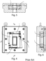
- By way of example, two different types of adjustable drawing dies with blocks of the prior art for the production of drawn products of quadrilateral section are shown, respectively, in
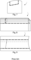
Figures 1-3 and4-6 attached hereto (referred to as "prior art"). The figures illustrate a front elevation view and two cross-sectional views along the planes identified by the lines A-A and B-B of each the two drawing dies. The fourblocks 1 inside the drawing die, visible inFig. 4 and shown in section inFigs. 2, 3 ,5 and 6 , are adjustable by the operators, and are blocked by wedges, shims and adjustment screws inside the box. They have a substantially parallelepiped shape with an external surface having a slightly convex curvature in the direction of the length of the block, and a slightly concave curvature in the direction of its width, as also shown inFigures 7-9 . The latter figures (also marked as "prior art") represent three orthogonal views of asingle block 1 of the prior art. In the composition of the internal surface of the die, the concave surface of the first block couples perfectly with the convex surface of the second block, arranged at a right angle to the first. In turn, the concave surface of the second block couples perfectly with the convex surface of the third block, and the concave surface of the latter couples in the same way with the convex surface of the fourth block, thus closing the entire system. - On the other hand, in an adjustable drawing die with saddles and abutments for the production of drawn products of quadrilateral cross-section, which is composed of two abutments and two saddles, the abutments are elements similar to the blocks, also made of steel with cemented carbide inserts or integral in cemented carbide. Said abutments, however, have only one curved external surface, the convex one in the direction of the length of the element. The saddles, in turn, are produced entirely of cemented carbide and have three curved surfaces: two concave surfaces intended to mate with the two opposite convex surfaces of the abutments, and one convex surface, orthogonal to the first two, lying along the hole of the die. In this way, by closing the system, it is possible to form, as in the case of the adjustable drawing die with blocks, the geometry of the flat drawn product that is intended to be obtained.
- Compared to adjustable drawing dies with blocks, adjustable drawing dies with saddles have the advantage of being more quickly ready, because one of the two dimensions of the drawn product is fixed, and is due to the dimension of the two saddles which, coupled with the abutments, define its thickness. Compared to adjustable dies with blocks, adjustable dies with abutments and saddles, however, are less adjustable, because in order to have different drawn product thicknesses it is necessary to mount different pairs of saddles.
- As can be seen in
Figure 7 , in a block the curvature of the convex surface is not centered with respect to the width of the block, rather the center of curvature has a displacement that can vary from a minimum of 5 mm to a maximum of 50 mm. For saddles and abutments, however, the curvatures of both the convex and concave surfaces are exactly centered with respect to the thickness and width of the piece itself. - The displacement of the center of curvature of the upper surface of the block allows to obtain a reduction zone during the deformation of the bars that is more or less long. The more such displacement is dimensionally large the greater is the reduction in cross-section section from the input laminate to the finished drawing size.
- According to the current technique, the main components of an adjustable drawing die are made entirely of cemented carbide, or with a cemented carbide insert or piece brazed on the steel support. Both of these solutions have advantages and disadvantages.
- The solution with a block entirely made of cemented carbide is an excellent solution for drawing machines for small-sized bars (from 25x30 mm to 30x40 mm). This avoids the brazing process necessary to stably couple the cemented carbide inserts to the steel box. In addition, the hardness of the contact walls with the adjustable drawing die box is that of the cemented carbide itself, therefore very high. A further advantage is the possibility of treating the insert with coatings obtained by CVD (Chemical Vapour Deposition), which can increase the duration of the insert without causing any problems to the structure of the block, being this integral.
- However, if the cross-section size and the lengths required for drawing become important, to have an integral block of hard metal entails a very high cost of raw material. Further, due to the high hardness of the hard metal also a higher risk of fragility of the system is incurred.
- The solution with a brazed insert, which is shown in the attached
Figures 7-9 relating to the prior art, involves a reduction in the cost of the raw material, but at the same time a significant reduction in the hardness of the steel surfaces of the block itself. This occurs especially in the contact area between the two materials, steel and cemented carbide (which are actually three, also considering the brazing alloy). In the three views ofFigures 7-9 , the surfaces where, with the current brazing system, the solder is positioned for the purpose of stably connecting the cemented carbide insert to the steel block are highlighted with a dotted line. The surfaces of the steel component, even if hardened to a hardness above 50 HRC, undergo tempering due to overheating during the brazing process, which is more important in value the closer one gets to the brazing-saturated areas. Heating to temperatures that are usually between 650°C and 720°C, depending on the type of solder used, is necessary to obtain a brazing that can resist breaking loads of even more than 50 kg/mm2. - The above means that at the end of all the working phases there will be areas of the block having different hardness values. Furthermore, areas of different hardness lead to internal stresses that give rise to critical areas in the block.
- In addition, in the case of drawing non-ferrous materials, in which the application would require the use of a cemented carbide with higher hardness characteristics, the tendency is to choose the integral solution, or to avoid using blocks with binder contents below 15%. This is because for these types of carbides the residual internal stresses present after brazing can often lead to the triggering of cracks in the carbide itself.
- Lastly, the brazed insert solution does not allow coating the block with the CVD technique, because the deposition temperatures required for chemical coatings are significantly higher than the melting temperature of the solder used.
- The fact that with the use of brazed blocks there may be zones with different hardness values in the block may lead to the emergence of problems during the drawing phase. Said problems include the following ones:
- 1) Premature wear due to friction between the block and the supporting surface.
- 2) Failure of the softer surfaces that have undergone the greatest tempering during the brazing phase: the lateral planes of the block will no longer be parallel as before installation.
- 3) Potential plastic advancement of the cemented carbide inside the steel support.
- It should be noted that even if the stresses to be counteracted were not so high as to trigger these critical effects, the brazing phase always involves the addition of internal stresses in the two materials. Such stresses are particularly risky in the carbide component, resulting in some cases in the triggering of cracks.
- Another example of an adjustable drawing die of the prior art is described in US patent
US 3436951 (assignee: Carmet Company, Pittsburgh, USA). The document describes an adjustable drawing die with blocks comprising wedge-shaped adjustment means, which blocks form a drawing opening that can be adjusted without dismantling the die itself. Also in this case, the four blocks forming the rectangular hole of the die are equipped with a cemented carbide insert, which can be fixedly secured to the steel support by brazing. - As further examples belonging to the prior art, the patent
GB 577235 GB 473856 GB 1234831 - In light of the prior art described above, the present invention aims to create a block (or an abutment) for mechanically connected dies that combines the advantages and eliminates the defects of the current systems mentioned above. Starting from the raw material, a mechanically connected block (or a mechanically connected abutment) would have a cemented carbide insert and a steel support, to achieve a reduction in the costs of the cemented carbide. Furthermore, the steel support, not being brazed, would not be affected by drops in hardness caused by overheating of the brazing. Furthermore, the exclusively mechanical connection of the insert to the support would allow the most suitable cemented carbide to be used for the application at any given time: harder carbides for applications of non-ferrous materials, tougher carbides where the material to be drawn is a high-alloy ferrous material. Finally, a mechanically connected block (or abutment) would have the ability to be disassembled and reassembled at the end of the polishing procedure, with the added benefit of being able to use CVD coating processes to make the block itself even more performing in terms of durability.
- With this object, according to the present invention, an exclusively mechanical connection has been developed between the steel support of a block (or an abutment) of an adjustable drawing die and the relative cemented carbide insert. Such connection is able to guarantee permanent and firm contact between the support and the insert and, at the same time, an optimal and long-lasting performance of the resulting drawing die.
- According to the invention, specific connection means have been provided, specifically sized and cooperating with each other to ensure that the components of the block (or abutment) are stably and firmly attached to each other. Each element (block or abutment) according to the invention, which is obviously mounted in a drawing die together with other elements (all identical to each other in the case of dies with blocks, or together with complementary saddles in the case of dies with abutments and saddles) to make up the sides of the hole of the die, is made up of three main components. Such components are a steel support, a cemented carbide insert and a rear closing element.
- The system of the invention provides firstly a mechanical connection configured as a dovetail between the steel support and the cemented carbide insert in the direction of the length of the element. Said connection prevents the insert from moving away from its housing in the support. Secondly a longitudinal tapering of the insert is provided, which narrows towards the front part of the block and prevents any forward movement of the carbide component during the work phase.
- For assembly, the system is closed by connecting the support assembly and the insert to the rear closing element by means of at least two collar screws, which connect the two steel elements to each other. The rear closing element of the steel component also prevents the potential movement backward of the insert.
- Furthermore, the use of collar screws ensures complete locking of the system in place, as well as the possibility of repeatedly disassembling it without problems.
- The dovetail-shaped connection between the cemented carbide insert and the steel support is such that the two opposite longitudinal vertical faces of the insert, and correspondingly the two longitudinal vertical flanks of its housing in the support, are not exactly on two parallel planes. Specifically, these two faces are inclined by an angle between 0.5° and 10°, preferably between 2° and 6°, towards the inside of the insert. Such an inclination, highlighted more clearly, for an exemplary embodiment, in Figure 13A, is able to ensure permanent contact between the surfaces of the two materials, cemented carbide and steel.
- As already noted, to prevent the insert from sliding forward with respect to the support, which event would still be possible with the dovetail connection still having one degree of freedom, the insert is also tapered lengthwise, i.e. it narrows towards the front of the block. This is shown more clearly in the plan views of
Figures 12 and 15B for an exemplary embodiment. The angle of the taper may be between 0.2° and 5°, and preferably is between 0.5° and 2°, and prevents any advancing movement of the carbide component during machining. - Finally, possible sliding of the cemented carbide insert backward with respect to the support is prevented by the rear closing element, which is connected to the steel support by means of two or more collar screws.
- The specific features of the invention, as well as its advantages and the relative modes of implementing it, will become evident with reference to the detailed description presented below, and to its specific embodiments, illustrated by way of example in the attached drawings, in which:
-
Figures 1, 2 and 3 , already discussed above, show respectively a front elevation view and two cross-sectional views along the planes identified by the lines A-A and B-B of a first adjustable drawing die of the prior art; -
Figures 4, 5 and 6 , already discussed above, show respectively a front elevation view and two cross-sectional views along the planes identified by the lines A-A and B-B of a second adjustable drawing die of the prior art; -
Figures 7, 8 and 9 , already discussed above, show respectively three orthogonal views, respectively front, side and plan view, of a brazed die block for adjustable dies of the prior art; -
Figure 10 shows an exploded perspective view of an embodiment of the mechanically connected block according to the invention; -
Figures 11A and 11B show two perspective views of the block ofFigure 10 fully assembled; -
Figure 12 shows a plan view of the same block ofFigures 11A and 11B ; -
Figure 13 shows a front elevation view of the component that constitutes the steel support of the block ofFigure 10 ; -
Figures 14A and 14B show two orthogonal views, front and side respectively, of the rear closure component of the block ofFigures 10 et seq.; -
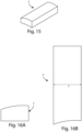
Figure 15 shows a perspective view of the cemented carbide insert of the block ofFigures 10 et seq.; -
Figures 16A and 16B show, respectively, a front elevation and a plan view of the cemented carbide insert ofFigure 15 ; -
Figure 17 shows an exploded perspective view of a variant of a mechanically connected block not included in the invention; -
Figures 18A and 18B show two perspective views of the block ofFigure 17 fully assembled; -
Figures 19A and 19B show, respectively, a plan view and a front elevation of the same block ofFigure 17 ; and -
Figures 20A and 20B show two orthogonal views, respectively front and side, of the rear closure component of the block ofFigures 17 et seq.. - The present invention specifically provides a block or an abutment for an adjustable drawing die, said block or abutment comprising:
- a substantially parallelepiped steel support with a longitudinal face having a convex surface, interrupted by a housing for a cemented carbide insert also substantially parallelepiped;
- a cemented carbide insert having a shape complementary to said housing and with a longitudinal face having a convex surface in continuity with that of said support;
- a rear closing element made of steel;
- wherein the support and the insert are mechanically connected, and the assembly of steel support with cemented carbide insert inserted therein is configured to form, with said convex surface, one of the working surfaces of the adjustable die;
- characterized in that:
- the connection between the steel support and the cemented carbide insert consists of:
- a) a longitudinal dovetail coupling between the support and the insert, the longitudinal side faces of the insert and correspondingly the longitudinal side faces of the housing in the support being inclined towards the longitudinal axis of the insert,
- b) a longitudinal tapering of the cemented carbide insert, and correspondingly of the housing in the support, along their length and towards their front end, and
- c) a screw coupling between the rear closing element and the support, the rear closing element being crossed by two or more through holes and the support presenting as many blind holes in corresponding positions;
- and in that the block or abutment also comprises two or more screws for screw coupling.
- the connection between the steel support and the cemented carbide insert consists of:
- Further characteristics of the block or abutment according to the invention are defined in the dependent claims attached to this description.
- The invention also includes the methods of producing the block or abutment according to the invention, which are detailed, with reference to a specific example and independently of the sizes of the piece, in the final part of Example 1 reported below.
-
Figures 10, Figures 11A and 11B of the attached drawings show an exploded perspective view of the various elements of an embodiment of a block according to the invention (Figure 10 ) and two perspective views of the same block fully assembled (Figures 11A and 11B ). Theblock 1 depicted in the figures is intended to be mounted, together with three other blocks of the same type, in the box of an adjustable drawing die with blocks. - It should be noted, based on what is already known about adjustable dies and as already described here with reference to the prior art, that the same design illustrated here would be applicable to an abutment for dies of the type with abutments and saddles. The only exception would be that, in such case, the terminal
vertical face 11 of the block would be flat and not concave. - The figures show the
hardened steel support 2, configured to accommodate the cementedtungsten carbide insert 3 in the complementarily shapedhousing 5. Theinsert 3 and thehousing 5 are both shaped as will be described later. Thesupport 2 andinsert 3 assembly is closed by arear closing element 4 by means of a pair of collar screws 10. Thescrews 10 pass through therear closing element 4, which is provided for this purpose with two throughholes 8, and engage with their thread in the internally threadedblind holes 9. - According to the invention, the two longitudinal lateral faces 6 of the
insert 3, and correspondingly the two longitudinal lateral faces 7 of thehousing 5 in thesupport 2, are inclined towards the longitudinal axis of theinsert 3, so as to form a dovetail connection. This detail, barely perceptible inFigure 10 given the small inclination, is shown more clearly inFigure 13 , which represents a front elevation view of thesupport 2 only. In the view inFigure 13 , the dovetail shape of theinsert 3 is more evident, and the inclination angle of the twolongitudinal faces 7 of thehousing 5 is also indicated, in the specific case exemplified being 2°. - At the same time, as also indicated by the dotted lines in
Figure 13 and as shown more clearly inFigure 12 , which represents a plan view of the assembledblock 1, the cementedcarbide insert 3, and correspondingly thehousing 5 in the support, present a longitudinal tapering along their length, as they narrow towards their front end. Consequently, the two lines denoting their contact planes in plan are not parallel, but slightly convergent. In the exemplary embodiment shown in the figures, the angle formed by the two planes with each other is 1°. - With reference to
Figures 14A and 14B , which show two orthogonal views of theclosing element 4, respectively in front elevation (Figure 14A ) and lateral elevation (Figure 14B ), it should be noted that theclosing element 4, differently from the closing element of the prior art with brazed insert (shown inFigures 7-9 ), is closed by aclosing element 4 extending to the entire cross-section of the block. This technical solution is linked to the longitudinal tapering of theinsert 3, which must be able to be inserted into thehousing 5 by advancing it in the only possible direction, i.e. from the rear end of the block towards the front end, where theinsert 3 has a smaller cross-section. - The present invention will be further described below with reference to a specific embodiment thereof, presented for purely illustrative but not limitative purposes. Subsequently, for comparison purposes, a variant of the block for adjustable drawing die with mechanically connected cemented carbide insert will be described, which is not included in the invention.
- Taking as an example the sizes of a block to be used for drawing a plate of average 120 mm width and 30-40 mm thickness, the operations necessary to produce a mechanically connected block according to the invention are described below.
- The following starting elements are necessary to produce the block:
- two steel parallelepipeds; one measuring 136 mm x 81 mm x 71 mm and the other measuring 36 mm x 81 mm x 71 mm
- a cemented carbide parallelepiped measuring 46 mm x 25.5 mm x 126 mm, preferably already shaped as shown in the
Figures 15, 16A e 16B; - two collar screws which, for these sizes, have a diameter of 10 mm, M8 thread and 30 mm length, for example: ISO 7379-10-M8-30.
- The choice of the steel quality to be used must be made in such a way as to ensure that the steel can be tempered and hardened, after some roughing operations, in order to obtain hardness levels higher than 35 HRC; preferably higher than 45 HRC, and even more preferably higher than 50 HRC.
- In this case, a steel with Werkstoff-Nr: 1.2343 and tempered to 51-53 HRC was chosen.
- As regards the quality of cemented carbide, it is necessary to know, for an appropriate choice, the final application, between drawing of bars in ferrous materials or drawing of bars in non-ferrous materials. Based on this data, it is possible to identify the most suitable type of cemented carbide. Usually, for drawing of non-ferrous materials, harder carbide grades are used, with a binder content (generally cobalt) lower than 10%, while for applications with ferrous materials the binder content can reach even more than 25%.
- The following are the production steps to follow in order to obtain a block compliant with the specifications.
- The steel parallelepipeds must be checked and must present the characteristics mentioned above, and in any case must have at least 0.5 mm to 5.00 mm of machining allowance per dimension.
- The first step is to obtain, through a mechanical milling step, two semi-finished products that present characteristics close to those of the finished component but with minimal machining allowances, which are essential for hardening.
- After milling, both steel components are heat treated in order to obtain the pre-established hardness.
- The cemented tungsten carbide parallelepiped, or alternatively the related rough pre-shaped part, is machined on the planes with the curvatures and inclination angles of the faces necessary to be able to be coupled with the steel support according to the criteria of the invention. Such curvatures and inclinations are shown in
Figures 10-13 ,15, 16A and 16B , even if the inclinations, being minimal, are barely perceptible. - After the tempering phase, the steel support is machined either by grinding or with cutters dedicated to milling the tempered steel, to obtain the tapered and dovetail pocket according to the invention, but with sizes that allow interference. The latter can be in the range from 0.05% to 0.5%, preferably 0.2-0.3%.
- Once this is done, the steel support is placed in oven at temperatures between 250°C and 500°C, in relation to the interference chosen, and, once the set temperature has been reached, it is removed from the oven and the cemented carbide insert is inserted into the pocket previously made with the appropriate attention. After this, the system is closed with the rear closure and the collar screws.
- The block resulting from this operation is rigid and does not allow any movement of the cemented carbide component with respect to the steel support.
- One then proceeds through grinding, to obtain the convex upper surface of the block, and finally to grinding to obtain the concave terminal surface of the block itself.
- The final polishing through diamond pastes concludes the production cycle.
- If required, the cemented carbide insert can be removed from the block thus obtained to perform any surface coatings, by placing the block in oven after removing the rear closure, and treating it at the same temperature used previously.
- Once the cemented carbide piece has been coated with the most appropriate coating, the insert can be reinserted into the steel support by placing the support in the oven and heating to the same temperature used, and repeating the operations performed for the first assembly.
- A possible solution to the same technical problem underlying the invention is shown in
Figures 17, 18A and 18B ,19A and 19B, 20A and 20B of the attached drawings, where elements corresponding to those ofblock 1 of the invention have the same reference numbers. - The solution has the same characteristic of the dovetail connection between the cemented
carbide insert 3 and thesteel support 2, with the lateral faces 6 and 7 of theinsert 3 and of thehousing 5 inclined towards the longitudinal axis of the block. However, theinsert 3, and correspondingly thehousing 5 have the two faces in the lengthwise sense parallel and not tapered, as shown inFigures 17, 18A, 18B and19A . - Consequently, the
insert 3 can slide in a longitudinal direction, and to ensure the rigidity and non-movement of theinsert 3, it was necessary to insert one or more elements that block its relative sliding with respect to thesupport 2. It should be considered, in fact, that the closure of the block with therear closing element 4 and with only the connectingscrews 10 betweensupport 2 andrear closing element 4 would still allow theinsert 3 to slide forward. - In order to block the forward translation of the
insert 3 with respect to the block, one or twoadditional screws 12 were inserted in the lower area of the steel block. These screws pass through the throughholes 13 of thesteel support 2 and grip theinsert 3 by penetrating the corresponding internally threadedblind holes 14, as shown in the figures. - This type of mechanical fastening initially closed the system in a stable way, but added critical areas in the system itself, such critical areas corresponding to the
blind holes 14 made in the cementedcarbide insert 3. - In fact, in the subsequent phase of testing the performance of drawing dies made with the blocks described, it was found that after some operating tests the pieces broke. By carrying out some analyses it was discovered that the cracks on the
carbide insert 3 were triggered, for all four pieces produced, exactly in the area of the holes. The addition of the plunge erosion holes led to the triggering of micro-cracks, which, brought in the operative drawing field, caused the entire system to fail. - The present invention has been disclosed with particular reference to some specific embodiments thereof, but it should be understood that modifications and changes may be made to it by the persons skilled in the art without thereby departing from the scope of protection as defined in the attached claims.
Claims (10)
- A block or an abutment for an adjustable drawing die, said block or abutment comprising:- a substantially parallelepiped steel support (2) with a longitudinal face having a convex surface, interrupted by a housing (5) for a cemented carbide insert (3) also substantially parallelepiped;- a cemented carbide insert (3) having a shape complementary to said housing (5) and with a longitudinal face having a convex surface in continuity with that of said support (2);- a rear closing element (4) made of steel;wherein said support (2) and said insert (3) are mechanically connected, and the assembly of said steel support (2) with said cemented carbide insert (3) inserted therein is configured to form, with said convex surface, one of the working surfaces of the adjustable die;
characterized in that:the connection between said steel support (2) and said cemented carbide insert (3) consists of:a) a longitudinal dovetail coupling between said support (2) and said insert (3), the longitudinal side faces (6) of said insert (3) and correspondingly the longitudinal side faces (7) of said housing (5) in the support (2) being inclined towards the longitudinal axis of the insert (3),b) a longitudinal tapering of said cemented carbide insert (3), and correspondingly of said housing (5) in the support (2), along their length and towards their front end, andc) a screw coupling between said rear closing element (4) and said support (2), said rear closing element (4) being crossed by two or more through holes (8) and said support (2) presenting as many blind holes (9) in corresponding positions;and in that said block or abutment also comprises two or more screws (10) for said screw coupling. - The block or abutment according to claim 1, wherein the angle of inclination of said longitudinal side faces (6, 7) towards the longitudinal axis of the insert (3) is comprised between 0.5° and 10°.
- The block or abutment according to claim 2, wherein said inclination angle is comprised between 2° and 6°.
- The block or abutment according to any one of claims 1-3, wherein the tapering angle of said cemented carbide insert (3) and of said housing (5) in the support (2) along their length is comprised between 0.2° and 5°.
- The block or abutment according to claim 4, wherein said tapering angle is comprised between 0.5° and 2°.
- The block or abutment according to any one of the preceding claims, wherein said through holes (8) and, correspondingly, said blind holes (9) and said screws (10) are two in number.
- The block or abutment according to any one of the preceding claims, wherein said screws (10) are collar screws.
- A process for producing a block for an adjustable drawing die of the type with blocks or an abutment for an adjustable drawing die of the type with abutments and saddles as defined in claim 1, which process comprises the following operations:a) preparing two steel parallelepipeds of sizes respectively corresponding to the sizes of said steel support (2) and of said rear closing element (4) made of steel, each having 0.5 mm to 5.00 mm of machining allowance per size;b) obtaining, through mechanical milling, two semi-finished products having the same configuration of the respective final components, excluding the housing (5) of the support (2), and which semi-finished products have machining allowances of at least 0.2-0.5 mm, indispensable for the subsequent hardening operation;c) subjecting the two steel pieces resulting from operation b) to hardening in order to obtain the pre-established hardness;d) preparing a rough cemented carbide parallelepiped of sizes corresponding to those of said insert (3), or alternatively a corresponding rough pre-shaped element, and working it on the planes to obtain the curvatures and angles of inclination of the faces necessary for it to be coupled with said steel support (2);e) subjecting the support (2) resulting from operation c) to machining either by milling or with milling cutters dedicated to milling hardened steel, thus obtaining a housing (5) with a shape complementary to that of the insert (3), but with sizes that allow an interference between the two components;f) placing the support (2) in oven at temperatures between 250°C and 500°C, depending on a selected chosen interference fit, and, once the set temperature is reached, removing it from the oven and inserting the insert (3) in said housing (5);g) closing the block or abutment with said rear closing element (4) and said screws (10);h) milling said block or abutment to obtain the convex upper surface of said block or abutment.
- The process according to claim 8, wherein a block for an adjustable die of the type with blocks is produced and wherein, after said operation h), the following operation is performed:
i) milling said block to obtain the concave end surface of the block, which allows it to be coupled to an adjacent block of the drawing die. - The process according to claims 8 or 9, wherein after the preceding operations a final polishing operation is performed by means of diamond pastes.
Applications Claiming Priority (1)
| Application Number | Priority Date | Filing Date | Title |
|---|---|---|---|
| IT102023000013260A IT202300013260A1 (en) | 2023-06-27 | 2023-06-27 | MECHANICALLY FIXED BLOCK OR SHOULDER FOR DEMOUNTABLE DRAWING MACHINE, WITH THE POSSIBILITY OF COATING |
Publications (3)
| Publication Number | Publication Date |
|---|---|
| EP4484028A1 true EP4484028A1 (en) | 2025-01-01 |
| EP4484028C0 EP4484028C0 (en) | 2026-02-18 |
| EP4484028B1 EP4484028B1 (en) | 2026-02-18 |
Family
ID=88097483
Family Applications (1)
| Application Number | Title | Priority Date | Filing Date |
|---|---|---|---|
| EP24184499.2A Active EP4484028B1 (en) | 2023-06-27 | 2024-06-25 | Optionally coatable mechanically connected block or abutment for an adjustable drawing die |
Country Status (2)
| Country | Link |
|---|---|
| EP (1) | EP4484028B1 (en) |
| IT (1) | IT202300013260A1 (en) |
Citations (4)
| Publication number | Priority date | Publication date | Assignee | Title |
|---|---|---|---|---|
| GB473856A (en) | 1936-12-05 | 1937-10-21 | Herbert Ltd A | Adjustable drawing dies |
| GB577235A (en) | 1944-09-09 | 1946-05-09 | Tool And Steel Products Ltd | Improvements in or relating to adjustable drawing dies |
| US3436951A (en) | 1966-05-03 | 1969-04-08 | Carmet Co | Adjustable drawing die |
| GB1234831A (en) | 1967-07-07 | 1971-06-09 | Poudres Metalliques Alliages Speciaux Ugine Carbone | Improvements in expandable dies or die-plates for use in extrusion and drawing operations |
-
2023
- 2023-06-27 IT IT102023000013260A patent/IT202300013260A1/en unknown
-
2024
- 2024-06-25 EP EP24184499.2A patent/EP4484028B1/en active Active
Patent Citations (4)
| Publication number | Priority date | Publication date | Assignee | Title |
|---|---|---|---|---|
| GB473856A (en) | 1936-12-05 | 1937-10-21 | Herbert Ltd A | Adjustable drawing dies |
| GB577235A (en) | 1944-09-09 | 1946-05-09 | Tool And Steel Products Ltd | Improvements in or relating to adjustable drawing dies |
| US3436951A (en) | 1966-05-03 | 1969-04-08 | Carmet Co | Adjustable drawing die |
| GB1234831A (en) | 1967-07-07 | 1971-06-09 | Poudres Metalliques Alliages Speciaux Ugine Carbone | Improvements in expandable dies or die-plates for use in extrusion and drawing operations |
Also Published As
| Publication number | Publication date |
|---|---|
| IT202300013260A1 (en) | 2024-12-27 |
| EP4484028C0 (en) | 2026-02-18 |
| EP4484028B1 (en) | 2026-02-18 |
Similar Documents
| Publication | Publication Date | Title |
|---|---|---|
| RU2409454C2 (en) | End milling cutter for orbital milling | |
| EP1624988B9 (en) | Cutting tool inserts and methods to manufacture | |
| EP0595061B1 (en) | Extrusion die device and die insert therefor | |
| EP1918059A1 (en) | Friction stir welding tool and friction stir welding apparatus | |
| DE10242191A1 (en) | Milling tool for milling molds | |
| US20120240398A1 (en) | Method and apparatus for repairing turbine rotor | |
| AT15012U1 (en) | drilling | |
| EP4484028B1 (en) | Optionally coatable mechanically connected block or abutment for an adjustable drawing die | |
| JP7128185B2 (en) | Manufacturing method of cutting insert, cutting tool and cutting work | |
| EP2127793A1 (en) | Cutting element and machining tool | |
| US4583431A (en) | Self-sharpening coated tool constructions | |
| Astakhov et al. | Drilling technology: Fundamentals and recent advances | |
| Carbide | The designer’s guide to tungsten carbide | |
| Zimmerman et al. | Machinability test methods | |
| US20220250171A1 (en) | Rotary cutting method | |
| EP1339521A1 (en) | Method for joining articles and corresponding tool | |
| NL8200784A (en) | CUT INSERT FOR TURNING. | |
| DE202012008940U1 (en) | milling tool | |
| US12145204B2 (en) | Broaching tool, broaching machine comprising such a tool and method for machining a workpiece using such a machine | |
| EP2745969B1 (en) | Milling tool | |
| US3955446A (en) | Cutting tool for the continuous machining of metals and the method of making same | |
| KR20070025976A (en) | Sliding material and machine tool having same | |
| US4724699A (en) | Drawplate for hot drawing | |
| US20030002928A1 (en) | Hobbing cutter | |
| DE102016105847A1 (en) | Cutting body and cutting tool |
Legal Events
| Date | Code | Title | Description |
|---|---|---|---|
| PUAI | Public reference made under article 153(3) epc to a published international application that has entered the european phase |
Free format text: ORIGINAL CODE: 0009012 |
|
| STAA | Information on the status of an ep patent application or granted ep patent |
Free format text: STATUS: THE APPLICATION HAS BEEN PUBLISHED |
|
| AK | Designated contracting states |
Kind code of ref document: A1 Designated state(s): AL AT BE BG CH CY CZ DE DK EE ES FI FR GB GR HR HU IE IS IT LI LT LU LV MC ME MK MT NL NO PL PT RO RS SE SI SK SM TR |
|
| STAA | Information on the status of an ep patent application or granted ep patent |
Free format text: STATUS: REQUEST FOR EXAMINATION WAS MADE |
|
| 17P | Request for examination filed |
Effective date: 20250612 |
|
| GRAP | Despatch of communication of intention to grant a patent |
Free format text: ORIGINAL CODE: EPIDOSNIGR1 |
|
| STAA | Information on the status of an ep patent application or granted ep patent |
Free format text: STATUS: GRANT OF PATENT IS INTENDED |
|
| RIC1 | Information provided on ipc code assigned before grant |
Ipc: B21C 3/06 20060101AFI20251023BHEP Ipc: B21C 3/12 20060101ALI20251023BHEP Ipc: B21C 3/18 20060101ALI20251023BHEP |
|
| INTG | Intention to grant announced |
Effective date: 20251031 |
|
| GRAS | Grant fee paid |
Free format text: ORIGINAL CODE: EPIDOSNIGR3 |
|
| GRAA | (expected) grant |
Free format text: ORIGINAL CODE: 0009210 |
|
| STAA | Information on the status of an ep patent application or granted ep patent |
Free format text: STATUS: THE PATENT HAS BEEN GRANTED |
|
| AK | Designated contracting states |
Kind code of ref document: B1 Designated state(s): AL AT BE BG CH CY CZ DE DK EE ES FI FR GB GR HR HU IE IS IT LI LT LU LV MC ME MK MT NL NO PL PT RO RS SE SI SK SM TR |
|
| REG | Reference to a national code |
Ref country code: CH Ref legal event code: F10 Free format text: ST27 STATUS EVENT CODE: U-0-0-F10-F00 (AS PROVIDED BY THE NATIONAL OFFICE) Effective date: 20260218 Ref country code: GB Ref legal event code: FG4D |
|
| REG | Reference to a national code |
Ref country code: IE Ref legal event code: FG4D |
|
| U01 | Request for unitary effect filed |
Effective date: 20260225 |
|
| U07 | Unitary effect registered |
Designated state(s): AT BE BG DE DK EE FI FR IT LT LU LV MT NL PT RO SE SI Effective date: 20260303 |
|
| U20 | Renewal fee for the european patent with unitary effect paid |
Year of fee payment: 3 Effective date: 20260331 |