EP4484021A1 - Actuator and tool comprising the same - Google Patents
Actuator and tool comprising the same Download PDFInfo
- Publication number
- EP4484021A1 EP4484021A1 EP23181989.7A EP23181989A EP4484021A1 EP 4484021 A1 EP4484021 A1 EP 4484021A1 EP 23181989 A EP23181989 A EP 23181989A EP 4484021 A1 EP4484021 A1 EP 4484021A1
- Authority
- EP
- European Patent Office
- Prior art keywords
- pusher
- control element
- drive
- actuator according
- reel
- Prior art date
- Legal status (The legal status is an assumption and is not a legal conclusion. Google has not performed a legal analysis and makes no representation as to the accuracy of the status listed.)
- Withdrawn
Links
Images







Classifications
-
- F—MECHANICAL ENGINEERING; LIGHTING; HEATING; WEAPONS; BLASTING
- F16—ENGINEERING ELEMENTS AND UNITS; GENERAL MEASURES FOR PRODUCING AND MAINTAINING EFFECTIVE FUNCTIONING OF MACHINES OR INSTALLATIONS; THERMAL INSULATION IN GENERAL
- F16H—GEARING
- F16H19/00—Gearings comprising essentially only toothed gears or friction members and not capable of conveying indefinitely-continuing rotary motion
- F16H19/02—Gearings comprising essentially only toothed gears or friction members and not capable of conveying indefinitely-continuing rotary motion for interconverting rotary or oscillating motion and reciprocating motion
- F16H19/06—Gearings comprising essentially only toothed gears or friction members and not capable of conveying indefinitely-continuing rotary motion for interconverting rotary or oscillating motion and reciprocating motion comprising flexible members, e.g. an endless flexible member
- F16H19/0636—Gearings comprising essentially only toothed gears or friction members and not capable of conveying indefinitely-continuing rotary motion for interconverting rotary or oscillating motion and reciprocating motion comprising flexible members, e.g. an endless flexible member the flexible member being a non-buckling chain
Definitions
- the invention relates to an actuator and a tool incorporating an actuator.
- Actuators are known to transmit forces e.g. for positioning objects in machinery, appliances, tools and vehicles. To this end, actuators often move a carriage or pawl along a motion path.
- types of actuators include single-action actuators and double-action actuators.
- Single-action actuators are usually capable of transmitting a force in one direction only, e.g. by pulling. Examples of single-action actuators typically comprise slack force-transmitting elements such as ropes, chains, wires, belts, ribbons, or tapes.
- Double-action actuators are usually capable of transmitting a force in two opposite directions, e.g. by pulling and pushing. Examples of double-action actuators typically comprise rigid force-transmitting elements such as rods, linkages, spindles, or gear racks.
- single-action actuators One constraint with single-action actuators relates to resetting the actuator in a direction opposite the direction of action.
- a secondary mechanism acting in that opposite direction such as an additional actuator, however increasing complexity and costs.
- single-action actuators act against gravity or the force of a bias spring, however consuming additional energy.
- the force-transmitting element is at least as long as its travel length, doubling the space needed. Efforts have been made to reduce the space by the use of collapsible elements such as telescopic cylinders, however increasing complexity and costs.
- an actuator that comprises a control element configured to move along a predetermined motion path, a first drive that drives the control element in a first direction along the motion path, a pusher configured to transmit a pushing force from the first drive onto the control element to drive the control element in the first direction, and a reel, wherein the pusher is wound on the reel. Winding the pusher on the reel may allow for a reduction of space needed, without losing the capability of pushing the control element.
- the actuator further comprises a second drive that drives the control element in a second direction opposite the first direction, wherein the pusher is configured to transmit a pulling force from the second drive onto the control element.
- the first drive and the second drive are identical.
- the first drive is different from the second drive.
- the first drive comprises a rotor which drives the pusher in the direction of the pushing force.
- the first drive comprises a motor that rotationally drives the rotor.
- the motor is an electric, hydraulic and/or pneumatic motor.
- the rotor engages the pusher.
- the rotor engages the pusher by a friction lock and/or an interlock, such as a toothing.
- the pusher comprises a plurality of recesses arranged along the first direction, wherein the rotor comprises a plurality of teeth engaging the recesses to drive the pusher.
- the reel comprises the rotor.
- the pusher is wound on the rotor.
- the first drive comprises a spring that biases the pusher in the direction of the pushing force.
- the pusher comprises the spring.
- the motion path is straight. According to an alternative embodiment, the motion path is curved.
- the pusher has a first end attached to the reel and/or a second end attached to the control element.
- the pusher is formed as a belt.
- the pusher is formed as a metal, alloy or plastic belt.
- the belt bulges across the direction of the pushing force when the belt transmits the pushing force from the first drive onto the control element.
- the pusher is formed as a wire.
- the pusher is formed as a metal, alloy or plastic wire.
- the actuator comprises a guide element, such as a guide rail, configured to guide the pusher and/or the control element in the direction of the motion path.
- the guide element has a profile comprising a recess, and wherein the pusher and/or the control element is partly or completely received in the recess to guide the pusher and/or the control element in the direction of the motion path.
- the guide element has an entering end where the pusher enters the guide element when the pusher is unwound from the reel, and wherein the motion path, at the entering end, is oriented tangential to the reel and/or pusher wound on the reel.
- the entering end pivots about a pivot axis to accommodate for changes of a winding radius of the pusher on the reel.
- the guide element comprises a plurality of openings to remove contamination, such as dust.
- control element is a pawl.
- the reel comprises a sprocket having a plurality of gear teeth, and wherein the pusher has a plurality of holes configured to engage with the plurality of gear teeth to drive the pusher.
- the actuator comprises a controller, such as an electronic controller, configured to determine a position and/or a speed of the control element and to control driving the control element in dependence of a detected position and/or speed.
- the actuator further comprises a position sensor configured to detect a position of the control element and transmit a signal indicative of a detected position of the control element to the controller.
- a tool such as a handheld tool, comprising a working piston configured to move along a working axis, a piston drive configured to drive the working piston along the working axis from a start position to an end position, and a piston reset device configured to reset the working piston from the end position to the start position and comprising an actuator as defined above.
- the tool is a driving tool comprising a receptacle configured to temporarily receive a fastening element, wherein the working piston drives the fastening element from the receptacle into a substrate when the piston drive drives the working piston from the start position to the end position.
- Fig. 1 shows a tool, or driving tool 10 for driving a fastening element, e.g. a nail or bolt, into a substrate in a side view.
- the driving tool 10 has a working piston configured as a driving piston for driving a fastening element into a substrate, and a housing 20 accommodating the working piston and a piston drive configured to drive the working piston along a working axis from a start position to an end position.
- the driving tool 10 is configured as a handheld tool and has a grip 30, a magazine 40 and a bridge 50 connecting the grip 30 to the magazine 40.
- a scaffold hook 60 for hanging the driving tool 10 on a scaffold or the like, a controller 580, signal lines 585 and an electrical battery 590 are fastened to the bridge 50.
- a trigger 34 and a hand switch 35 are arranged on the grip 30.
- the driving tool 10 further has a guide channel 700 for guiding the fastening element and a press-on probe 750 for detecting a pressing the driving tool 10 on the substrate.
- An alignment of the driving tool 10 perpendicular to a surface of the substrate is supported by a support element 45.
- Fig. 2 shows the driving tool 10 with opened housing 20.
- An actuating device 70 for actuating the working piston is accommodated in the housing 20.
- the actuating device 70 comprises an electric motor for converting electrical energy from the electrical battery 590 into rotational energy, a transmission 400 for transferring a torque of the electric motor to a spindle drive 300, a roll train 260 for transmitting a force from the spindle drive 300 to a spring 200 and for transmitting a force from the spring 200 to the driving piston.
- the magazine 40 comprises a feed channel 42 that opens into a receptacle 44 which is configured to temporarily receive a fastening element.
- the working piston drives the fastening element from the receptacle 44 into a substrate when the piston drive drives the working piston from the start position to the end position.
- the driving tool 10 further has a piston reset device configured to reset the working piston from the end position to the start position.
- the piston reset device comprises an actuator as described below with respect to Figs. 3-28 .
- Figs. 3-4 show an actuator 110, e.g. for resetting the working piston of the driving tool 10 as shown in Figs. 1-2 .
- the actuator 110 comprises a control element 120, such as a pawl for engaging the working piston.
- the control element 120 moves along a predetermined straight motion path 130. In non-shown embodiments, the motion path may be curved.
- a first drive 140 drives the control element 120 in a first direction 150 along the motion path 130, such as a forward direction.
- a pusher 160 formed as a belt transmits a pushing force from the first drive 140 onto the control element 120 and thereby drives the control element 120 in the first direction 150.
- the actuator 110 further comprises a reel 170, and the pusher 160 is wound on the reel 170.
- the first drive 140 also works as a second drive that drives the control element 120 in a second direction opposite the first direction 150, such as a rearward direction. To this end, the pusher 160 transmits a pulling force from the second drive onto the control element 160. In a different embodiment (not shown), the first drive is different from the second drive.
- the first drive 140 comprises a rotor (shown in Figs. 8-9 ) which drives the pusher 160 in the direction of the pushing force, i.e. the first direction 150.
- the rotor is hidden under a cover 180 and is driven by an electric motor 190 that rotationally drives the rotor.
- the motor is an hydraulic and/or pneumatic motor.
- the rotor engages the pusher 160 to drive the pusher 160.
- the rotor comprises a plurality of teeth that engage, or interlock, with a plurality of recesses 165, one after another, provided on the pusher 160 along the first direction 150, to drive the pusher 160.
- Figs. 5-7 show further embodiments of an actuator 210 comprising a control element 220 that moves along a predetermined motion path 230.
- a first drive 240 drives the control element 220 in a first direction 250 along the motion path 230.
- a pusher 261 formed as a belt transmits a pushing force from the first drive 240 onto the control element 220 and thereby drives the control element 220 in the first direction 250.
- the actuator 210 further comprises a reel 270, and the pusher 261 is wound on the reel 270.
- a second drive 245 drives the control element 220 in a second direction opposite the first direction 250. To this end, the pusher 261 transmits a pulling force from the second drive 245 onto the control element 261.
- the first drive 240 is different from the second drive 245 and is arranged outside the reel 270.
- the first drive 240 comprises a rotor 241 rotationally driven by a motor.
- the rotor 241 comprises a plurality of teeth 242 that engage, or interlock, with a plurality of recesses provided on the pusher 261 along the first direction 250, to drive the pusher 261.
- the first drive 240 is different from the second drive 245.
- the first drive 240 comprises a rotor 243 rotationally driven by a motor.
- the rotor 243 engages the pusher 261 by a friction lock to drive the pusher 160.
- the pusher 261 is sandwiched between the rotor 243 and a counter-rotor 244 to increase the friction lock.
- the first drive 240 also works as the second drive.
- the first drive 240 comprises a linear motor comprising a plurality of permanent magnets 247 attached to the pusher 261 and a plurality of stationary coils 248 engaging with the magnets 247 by electromagnetic forces.
- the first drive 240 also works as the second drive.
- Figs. 8-9 show further embodiments of an actuator 310 comprising a control element 320 that moves along a predetermined motion path 330.
- a first drive 340 drives the control element 320 in a first direction 350 along the motion path 330.
- a pusher 360 transmits a pushing force from the first drive 340 onto the control element 320 and thereby drives the control element 320 in the first direction 350.
- the actuator 310 further comprises a reel 370, and the pusher 360 is wound on the reel 370.
- the reel 370 comprises a rotor 375 of the first drive 340.
- the pusher 360 is wound on the rotor 375.
- the first drive 340 comprises a spring 349 that biases the rotor 375 and thus the pusher 360 in the direction of the pushing force.
- the pusher comprises the spring.
- the first drive consists of the spring, i.e. the spring is the only drive of the pusher in the first direction.
- a first end 361 of the pusher 360 is attached to the reel 370, whereas a second end 362 of the pusher 360 is attached to the control element 320.
- the reel 370 comprises a sprocket 371 having a plurality of gear teeth 372.
- the gear teeth 372 are configured to engage a plurality of holes provided in the pusher 360 to drive the pusher 360. While not visible in Figs. 8-9 , the holes may be shaped and formed like the recesses 165 shown in Fig. 3 .
- the actuator 310 further comprises an electronic controller 315.
- the controller 315 determines a position and a speed of the control element 320 and controls driving of the control element 320 in dependence of its detected position and/or speed via a control line 316.
- the actuator 310 comprises a position sensor 317 that detects a position of the control element 320 and transmits a signal indicative of a detected position of the control element 320 to the controller 315 via a signal line 318.
- the actuator 310 comprises a wave emitter-receiver 319 that emits a wave, such as an optical or acoustical wave, to the control element 320, and that receives a response wave reflected by the control element 320.
- the wave emitter-receiver then transmits a signal indicative of a detected position of the control element 320 to the controller 315.
- Figs. 10-11 show an actuator 410 comprising a control element (not shown), a pusher 460, and a guide element 485 formed as a guide rail.
- the actuator 410 further comprises a reel 470, and the pusher 460 is wound on the reel 470.
- the guide element 485 guides the pusher 460 in the direction of a motion path.
- the guide element 485 further has an entering end 486 where the pusher 460 enters the guide element 485 when the pusher 460 is unwound from the reel 470.
- the motion path is oriented tangential to the pusher 460 wound on the reel 470.
- the entering end 486 pivots about a pivot axis 487 to accommodate for changes of a winding radius of the pusher 460 on the reel 470.
- the whole guide element pivots about the pivot axis 487 which is positioned at a far end of the guide element 485.
- a section of the guide element pivots about the pivot axis 487 which is positioned at a far end of the section of the guide element 485.
- the motion path may be curved along the pivoted and unpivoted sections of the guide element 485.
- Fig. 12 shows a pusher 560 partly wound on a reel (not shown) and partly unwound from the reel.
- the pusher 560 is formed as a metal belt and bulges across the direction of the pushing force when the belt transmits the pushing force from a first drive (not shown) onto a control element (not shown), as shown at the cross-section A-A. If wound on the reel, the belt is bent around the reel and does not bulge, i.e. has a flat cross-section, as shown at B-B.
- the pusher is formed as a wire, such as a metal, alloy or plastic wire.
- Fig. 13 shows a pusher 660 formed as a belt consisting of three layers of different metal, alloy, plastic and/or textile material.
- the pusher consists of two, four or more layers. The layers may be joint together by lamination, gluing etc.
- Figs. 14-15 show a pusher 760 and a control element 720 attached to the pusher 760.
- the pusher 760 comprises two brushes 765 to remove dust or contamination from a guide element (not shown).
- all bristles 766 of the brush 765 are oriented perpendicular to a motion path of the pusher 760.
- the bristles 767 of the brush 765 are inclined from a direction of a motion path by an acute angle. Thereby, undesired friction is reduced when the pusher 760 is pushed by a pushing force (to the right in Fig. 15 ).
- Figs. 16-17 show a top view of two embodiments of a pusher 860, 960 and a control element 820, 920.
- control element 820 has a rectangular shape in the top view, wherein a length L of the control element 820, as measured in a direction of a motion path, is greater than a width W of the control element 820, as measured across the motion path.
- control element 920 has a head-and-neck contour and the pusher 960 has a contour corresponding to the head-and-neck contour of the control element 920, such that the control element 920 is interlocked with the pusher 960.
- Figs. 18-22 show embodiments of a pusher 1060, 1160, 1260, 1360, 1460 and a control element 1020, 1120, 1220, 1320, 1420.
- a thickness d pawl of the control element 1020 is substantially the same as a thickness d tape of the pusher 1060.
- a thickness d pawl of the control element 1120 is substantially greater than a thickness d tape of the pusher 1160.
- an end of the pusher 1260 is embedded in the control element 1220.
- an end of the pusher 1360 is attached to the control element 1320, e.g. via a rivet 1321.
- an end of the pusher 1460 is attached to the control element 1420, via an intermediate element 1429.
- the intermediate element 1429 is attached to the pusher 1460 and the control element 1420 e.g. via rivets 1421, 1422.
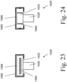
- Figs. 23-27 show embodiments of a guide element in a cross-sectional view.
- the guide element is configured to guide the pusher and/or the control element in the direction of the motion path.
- a guide element 1585 has a recess 1588 to enclose a base part 1525 of a control element 1520.
- the control element 1520 further comprises a pawl part 1526 projecting out of the guide element 1585 without contacting the guide element 1585.
- a pusher 1560, or an end thereof, is embedded in the base part 1525 of the control element 1520.
- a guide element 1685 has a recess 1688 to enclose a base part 1625 of a control element 1620 and two counter-guiding elements 1627 attached to a pusher 1660, as is the base part 1625.
- the control element 1620 further comprises a pawl part 1626 projecting out of the guide element 1685 without contacting the guide element 1685.
- a guide element 1785 has a recess 1788 to enclose a base part 1725 of a control element 1720 and a pusher 1760 such that both the control element 1720 and the pusher 1760 are guided.
- the control element 1720 further comprises a pawl part 1726 projecting out of the guide element 1785 without contacting the guide element 1785.
- a guide element 1885 has two guide rails defining a recess 1888 to enclose a pusher 1860 therebetween.
- a control element 1820 is attached to the pusher 1860 comprising a base part 1825 and a pawl part 1826 and projecting out of the guide element 1885 without contacting the guide element 1885.
- a guide element 1985 has a recess 1988 to enclose a pusher 1960.
- Fig. 28 shows a pusher 2060 and a guide element 2085 formed as a guide rail.
- the pusher 2060 is guided in the guide element 2085 in a direction of a motion path 2030 of the pusher 2060.
- the guide element 2085 comprises a plurality of openings 2089 to remove contamination, such as dust, when the pusher 2060 moves along the motion path 2030.
- the actuator as described herein above may be used in a number of applications, e.g. sliders in machines, actuation of drawers, operation of sliding doors, retraction of pistons in nailing tools, blinds and shutters, assembly belts and trays, agricultural machinery etc.
Landscapes
- Engineering & Computer Science (AREA)
- General Engineering & Computer Science (AREA)
- Mechanical Engineering (AREA)
- Portable Nailing Machines And Staplers (AREA)
Abstract
An actuator and a tool are disclosed that comprise a control element (120) configured to move along a predetermined motion path, a first drive (140) that drives the control element in a first direction along the motion path, a pusher (130) configured to transmit a pushing force from the first drive onto the control element to drive the control element in the first direction, and a reel (170), wherein the pusher is wound on the reel.
Description
- The invention relates to an actuator and a tool incorporating an actuator. Actuators are known to transmit forces e.g. for positioning objects in machinery, appliances, tools and vehicles. To this end, actuators often move a carriage or pawl along a motion path. Generally, types of actuators include single-action actuators and double-action actuators. Single-action actuators are usually capable of transmitting a force in one direction only, e.g. by pulling. Examples of single-action actuators typically comprise slack force-transmitting elements such as ropes, chains, wires, belts, ribbons, or tapes. Double-action actuators are usually capable of transmitting a force in two opposite directions, e.g. by pulling and pushing. Examples of double-action actuators typically comprise rigid force-transmitting elements such as rods, linkages, spindles, or gear racks.
- One constraint with single-action actuators relates to resetting the actuator in a direction opposite the direction of action. Generally, there is a need of a secondary mechanism acting in that opposite direction, such as an additional actuator, however increasing complexity and costs. In some applications, single-action actuators act against gravity or the force of a bias spring, however consuming additional energy.
- One constraint with double-action actuators relates to size. Usually, the force-transmitting element is at least as long as its travel length, doubling the space needed. Efforts have been made to reduce the space by the use of collapsible elements such as telescopic cylinders, however increasing complexity and costs.
- The above constraints are addressed by an actuator that comprises a control element configured to move along a predetermined motion path, a first drive that drives the control element in a first direction along the motion path, a pusher configured to transmit a pushing force from the first drive onto the control element to drive the control element in the first direction, and a reel, wherein the pusher is wound on the reel. Winding the pusher on the reel may allow for a reduction of space needed, without losing the capability of pushing the control element.
- According to an embodiment, the actuator further comprises a second drive that drives the control element in a second direction opposite the first direction, wherein the pusher is configured to transmit a pulling force from the second drive onto the control element. In a preferred embodiment, the first drive and the second drive are identical. In another preferred embodiment, the first drive is different from the second drive.
- According to another embodiment, the first drive comprises a rotor which drives the pusher in the direction of the pushing force.
- According to another embodiment, the first drive comprises a motor that rotationally drives the rotor. In a preferred embodiment, the motor is an electric, hydraulic and/or pneumatic motor.
- According to another embodiment, the rotor engages the pusher. In a preferred embodiment, the rotor engages the pusher by a friction lock and/or an interlock, such as a toothing.
- According to another embodiment, the pusher comprises a plurality of recesses arranged along the first direction, wherein the rotor comprises a plurality of teeth engaging the recesses to drive the pusher.
- According to another embodiment, the reel comprises the rotor. In a preferred embodiment, the pusher is wound on the rotor.
- According to another embodiment, the first drive comprises a spring that biases the pusher in the direction of the pushing force. In a preferred embodiment, the pusher comprises the spring.
- According to another embodiment, the motion path is straight. According to an alternative embodiment, the motion path is curved.
- According to another embodiment, the pusher has a first end attached to the reel and/or a second end attached to the control element.
- According to another embodiment, the pusher is formed as a belt. In a preferred embodiment, the pusher is formed as a metal, alloy or plastic belt. In another preferred embodiment, the belt bulges across the direction of the pushing force when the belt transmits the pushing force from the first drive onto the control element.
- According to another embodiment, the pusher is formed as a wire. In a preferred embodiment, the pusher is formed as a metal, alloy or plastic wire.
- According to another embodiment, the actuator comprises a guide element, such as a guide rail, configured to guide the pusher and/or the control element in the direction of the motion path. In a preferred embodiment, the guide element has a profile comprising a recess, and wherein the pusher and/or the control element is partly or completely received in the recess to guide the pusher and/or the control element in the direction of the motion path. In another preferred embodiment, the guide element has an entering end where the pusher enters the guide element when the pusher is unwound from the reel, and wherein the motion path, at the entering end, is oriented tangential to the reel and/or pusher wound on the reel. In an even more preferred embodiment, the entering end pivots about a pivot axis to accommodate for changes of a winding radius of the pusher on the reel. In another preferred embodiment, the guide element comprises a plurality of openings to remove contamination, such as dust.
- According to another embodiment, the control element is a pawl.
- According to another embodiment, the reel comprises a sprocket having a plurality of gear teeth, and wherein the pusher has a plurality of holes configured to engage with the plurality of gear teeth to drive the pusher.
- According to another embodiment, the actuator comprises a controller, such as an electronic controller, configured to determine a position and/or a speed of the control element and to control driving the control element in dependence of a detected position and/or speed. In a preferred embodiment, the actuator further comprises a position sensor configured to detect a position of the control element and transmit a signal indicative of a detected position of the control element to the controller.
- The above constraints are further addressed by a tool, such as a handheld tool, comprising a working piston configured to move along a working axis, a piston drive configured to drive the working piston along the working axis from a start position to an end position, and a piston reset device configured to reset the working piston from the end position to the start position and comprising an actuator as defined above. According to an embodiment, the tool is a driving tool comprising a receptacle configured to temporarily receive a fastening element, wherein the working piston drives the fastening element from the receptacle into a substrate when the piston drive drives the working piston from the start position to the end position.
- Further aspects and advantages of the fastening tool, associated parts and a method of use thereof will become apparent from the ensuing description that is given by way of example only and with reference to the accompanying drawings in which:
- Fig. 1
- illustrates a side view of a driving device,
- Fig. 2
- illustrates a side view of the driving device with opened housing,
- Fig. 3
- illustrates a perspective view of an actuator,
- Fig. 4
- illustrates a side view of the actuator shown in
Fig. 3 , - Fig. 5
- illustrates a side view of an actuator,
- Fig. 6
- illustrates a side view of an actuator,
- Fig. 7
- illustrates a side view of an actuator,
- Fig. 8
- illustrates a side view of an actuator,
- Fig. 9
- illustrates a side view of an actuator,
- Fig. 10
- illustrates a side view of an actuator,
- Fig. 11
- illustrates a side view of an actuator,
- Fig. 12
- illustrates a side view of a pusher,
- Fig. 13
- illustrates a perspective view of a pusher,
- Fig. 14
- illustrates a pusher,
- Fig. 15
- illustrates a pusher,
- Fig. 16
- illustrates a pusher and a control element,
- Fig. 17
- illustrates a pusher and a control element,
- Fig. 18
- illustrates a pusher and a control element,
- Fig. 19
- illustrates a pusher and a control element,
- Fig. 20
- illustrates a pusher and a control element,
- Fig. 21
- illustrates a cross-sectional view of a pusher and a control element,
- Fig. 22
- illustrates a cross-sectional view of a pusher and a control element,
- Fig. 23
- illustrates a control element and a guide element,
- Fig. 24
- illustrates a control element and a guide element,
- Fig. 25
- illustrates a pusher, a control element and a guide element,
- Fig. 26
- illustrates a pusher, a control element and a guide element,
- Fig. 27
- illustrates a pusher and a guide element, and
- Fig. 28
- illustrates a guide element.
-
Fig. 1 shows a tool, or drivingtool 10 for driving a fastening element, e.g. a nail or bolt, into a substrate in a side view. The drivingtool 10 has a working piston configured as a driving piston for driving a fastening element into a substrate, and ahousing 20 accommodating the working piston and a piston drive configured to drive the working piston along a working axis from a start position to an end position. The drivingtool 10 is configured as a handheld tool and has agrip 30, amagazine 40 and abridge 50 connecting thegrip 30 to themagazine 40. Ascaffold hook 60 for hanging the drivingtool 10 on a scaffold or the like, acontroller 580,signal lines 585 and anelectrical battery 590 are fastened to thebridge 50. Atrigger 34 and ahand switch 35 are arranged on thegrip 30. The drivingtool 10 further has aguide channel 700 for guiding the fastening element and a press-onprobe 750 for detecting a pressing thedriving tool 10 on the substrate. An alignment of the drivingtool 10 perpendicular to a surface of the substrate is supported by asupport element 45. -
Fig. 2 shows the drivingtool 10 with openedhousing 20. Anactuating device 70 for actuating the working piston is accommodated in thehousing 20. Theactuating device 70 comprises an electric motor for converting electrical energy from theelectrical battery 590 into rotational energy, atransmission 400 for transferring a torque of the electric motor to aspindle drive 300, aroll train 260 for transmitting a force from thespindle drive 300 to aspring 200 and for transmitting a force from thespring 200 to the driving piston. Themagazine 40 comprises afeed channel 42 that opens into areceptacle 44 which is configured to temporarily receive a fastening element. The working piston drives the fastening element from thereceptacle 44 into a substrate when the piston drive drives the working piston from the start position to the end position. The drivingtool 10 further has a piston reset device configured to reset the working piston from the end position to the start position. The piston reset device comprises an actuator as described below with respect toFigs. 3-28 . -
Figs. 3-4 show anactuator 110, e.g. for resetting the working piston of the drivingtool 10 as shown inFigs. 1-2 . Theactuator 110 comprises acontrol element 120, such as a pawl for engaging the working piston. Thecontrol element 120 moves along a predeterminedstraight motion path 130. In non-shown embodiments, the motion path may be curved. Afirst drive 140 drives thecontrol element 120 in afirst direction 150 along themotion path 130, such as a forward direction. Apusher 160 formed as a belt transmits a pushing force from thefirst drive 140 onto thecontrol element 120 and thereby drives thecontrol element 120 in thefirst direction 150. Theactuator 110 further comprises areel 170, and thepusher 160 is wound on thereel 170. Thefirst drive 140 also works as a second drive that drives thecontrol element 120 in a second direction opposite thefirst direction 150, such as a rearward direction. To this end, thepusher 160 transmits a pulling force from the second drive onto thecontrol element 160. In a different embodiment (not shown), the first drive is different from the second drive. - The
first drive 140 comprises a rotor (shown inFigs. 8-9 ) which drives thepusher 160 in the direction of the pushing force, i.e. thefirst direction 150. The rotor is hidden under acover 180 and is driven by anelectric motor 190 that rotationally drives the rotor. In non-shown embodiments, the motor is an hydraulic and/or pneumatic motor. The rotor engages thepusher 160 to drive thepusher 160. To this end, the rotor comprises a plurality of teeth that engage, or interlock, with a plurality ofrecesses 165, one after another, provided on thepusher 160 along thefirst direction 150, to drive thepusher 160. -
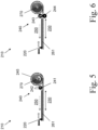
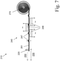
Figs. 5-7 show further embodiments of anactuator 210 comprising acontrol element 220 that moves along apredetermined motion path 230. Afirst drive 240 drives thecontrol element 220 in afirst direction 250 along themotion path 230. Apusher 261 formed as a belt transmits a pushing force from thefirst drive 240 onto thecontrol element 220 and thereby drives thecontrol element 220 in thefirst direction 250. Theactuator 210 further comprises areel 270, and thepusher 261 is wound on thereel 270. Asecond drive 245 drives thecontrol element 220 in a second direction opposite thefirst direction 250. To this end, thepusher 261 transmits a pulling force from thesecond drive 245 onto thecontrol element 261. Thefirst drive 240 is different from thesecond drive 245 and is arranged outside thereel 270. - In the embodiment shown in
Fig. 5 , thefirst drive 240 comprises arotor 241 rotationally driven by a motor. Therotor 241 comprises a plurality ofteeth 242 that engage, or interlock, with a plurality of recesses provided on thepusher 261 along thefirst direction 250, to drive thepusher 261. In the embodiment shown inFig. 5 , thefirst drive 240 is different from thesecond drive 245. - In the embodiment shown in
Fig. 6 , thefirst drive 240 comprises arotor 243 rotationally driven by a motor. Therotor 243 engages thepusher 261 by a friction lock to drive thepusher 160. Thepusher 261 is sandwiched between therotor 243 and a counter-rotor 244 to increase the friction lock. In the embodiment shown inFig. 6 , thefirst drive 240 also works as the second drive. - In the embodiment shown in
Fig. 7 , thefirst drive 240 comprises a linear motor comprising a plurality ofpermanent magnets 247 attached to thepusher 261 and a plurality ofstationary coils 248 engaging with themagnets 247 by electromagnetic forces. In the embodiment shown inFig. 7 , thefirst drive 240 also works as the second drive. -
Figs. 8-9 show further embodiments of anactuator 310 comprising acontrol element 320 that moves along apredetermined motion path 330. Afirst drive 340 drives thecontrol element 320 in afirst direction 350 along themotion path 330. Apusher 360 transmits a pushing force from thefirst drive 340 onto thecontrol element 320 and thereby drives thecontrol element 320 in thefirst direction 350. Theactuator 310 further comprises areel 370, and thepusher 360 is wound on thereel 370. Thereel 370 comprises arotor 375 of thefirst drive 340. Thepusher 360 is wound on therotor 375. Further, thefirst drive 340 comprises aspring 349 that biases therotor 375 and thus thepusher 360 in the direction of the pushing force. In non-shown embodiments, the pusher comprises the spring. In further embodiments, the first drive consists of the spring, i.e. the spring is the only drive of the pusher in the first direction. Afirst end 361 of thepusher 360 is attached to thereel 370, whereas asecond end 362 of thepusher 360 is attached to thecontrol element 320. Thereel 370 comprises asprocket 371 having a plurality ofgear teeth 372. Thegear teeth 372 are configured to engage a plurality of holes provided in thepusher 360 to drive thepusher 360. While not visible inFigs. 8-9 , the holes may be shaped and formed like therecesses 165 shown inFig. 3 . - The
actuator 310 further comprises anelectronic controller 315. Thecontroller 315 determines a position and a speed of thecontrol element 320 and controls driving of thecontrol element 320 in dependence of its detected position and/or speed via acontrol line 316. - In the embodiment shown in
Fig. 8 , theactuator 310 comprises aposition sensor 317 that detects a position of thecontrol element 320 and transmits a signal indicative of a detected position of thecontrol element 320 to thecontroller 315 via asignal line 318. - In the embodiment shown in
Fig. 9 , theactuator 310 comprises a wave emitter-receiver 319 that emits a wave, such as an optical or acoustical wave, to thecontrol element 320, and that receives a response wave reflected by thecontrol element 320. The wave emitter-receiver then transmits a signal indicative of a detected position of thecontrol element 320 to thecontroller 315. -
Figs. 10-11 show anactuator 410 comprising a control element (not shown), apusher 460, and aguide element 485 formed as a guide rail. Theactuator 410 further comprises areel 470, and thepusher 460 is wound on thereel 470. Theguide element 485 guides thepusher 460 in the direction of a motion path. Theguide element 485 further has an enteringend 486 where thepusher 460 enters theguide element 485 when thepusher 460 is unwound from thereel 470. At the enteringend 486, the motion path is oriented tangential to thepusher 460 wound on thereel 470. To this end, the enteringend 486 pivots about apivot axis 487 to accommodate for changes of a winding radius of thepusher 460 on thereel 470. - In the embodiment shown in
Fig. 10 , the whole guide element pivots about thepivot axis 487 which is positioned at a far end of theguide element 485. - In the embodiment shown in
Fig. 11 , only a section of the guide element pivots about thepivot axis 487 which is positioned at a far end of the section of theguide element 485. Here, the motion path may be curved along the pivoted and unpivoted sections of theguide element 485. -
Fig. 12 shows apusher 560 partly wound on a reel (not shown) and partly unwound from the reel. Thepusher 560 is formed as a metal belt and bulges across the direction of the pushing force when the belt transmits the pushing force from a first drive (not shown) onto a control element (not shown), as shown at the cross-section A-A. If wound on the reel, the belt is bent around the reel and does not bulge, i.e. has a flat cross-section, as shown at B-B. In non-show embodiments, the pusher is formed as a wire, such as a metal, alloy or plastic wire. -
Fig. 13 shows apusher 660 formed as a belt consisting of three layers of different metal, alloy, plastic and/or textile material. In non-shown embodiments, the pusher consists of two, four or more layers. The layers may be joint together by lamination, gluing etc. -
Figs. 14-15 show apusher 760 and acontrol element 720 attached to thepusher 760. Thepusher 760 comprises twobrushes 765 to remove dust or contamination from a guide element (not shown). - In the embodiment shown in
Fig. 14 , all bristles 766 of thebrush 765 are oriented perpendicular to a motion path of thepusher 760. - In the embodiment shown in
Fig. 15 , thebristles 767 of thebrush 765 are inclined from a direction of a motion path by an acute angle. Thereby, undesired friction is reduced when thepusher 760 is pushed by a pushing force (to the right inFig. 15 ). -
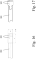
Figs. 16-17 show a top view of two embodiments of apusher control element - In the embodiment shown in
Fig. 16 , thecontrol element 820 has a rectangular shape in the top view, wherein a length L of thecontrol element 820, as measured in a direction of a motion path, is greater than a width W of thecontrol element 820, as measured across the motion path. - In the embodiment shown in
Fig. 17 , thecontrol element 920 has a head-and-neck contour and thepusher 960 has a contour corresponding to the head-and-neck contour of thecontrol element 920, such that thecontrol element 920 is interlocked with thepusher 960. -
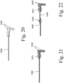
Figs. 18-22 show embodiments of apusher control element - In the embodiment shown in
Fig. 18 , a thickness dpawl of thecontrol element 1020 is substantially the same as a thickness dtape of thepusher 1060. - In the embodiment shown in
Fig. 19 , a thickness dpawl of thecontrol element 1120 is substantially greater than a thickness dtape of thepusher 1160. - In the embodiment shown in
Fig. 20 , an end of thepusher 1260 is embedded in thecontrol element 1220. - In the embodiment shown in
Fig. 21 , an end of thepusher 1360 is attached to thecontrol element 1320, e.g. via arivet 1321. - In the embodiment shown in
Fig. 22 , an end of thepusher 1460 is attached to thecontrol element 1420, via anintermediate element 1429. Theintermediate element 1429 is attached to thepusher 1460 and thecontrol element 1420 e.g. viarivets -
Figs. 23-27 show embodiments of a guide element in a cross-sectional view. In each embodiment, the guide element is configured to guide the pusher and/or the control element in the direction of the motion path. - In the embodiment shown in
Fig. 23 , aguide element 1585 has arecess 1588 to enclose abase part 1525 of acontrol element 1520. Thecontrol element 1520 further comprises apawl part 1526 projecting out of theguide element 1585 without contacting theguide element 1585. Apusher 1560, or an end thereof, is embedded in thebase part 1525 of thecontrol element 1520. - In the embodiment shown in
Fig. 24 , aguide element 1685 has arecess 1688 to enclose abase part 1625 of acontrol element 1620 and two counter-guiding elements 1627 attached to apusher 1660, as is thebase part 1625. Thecontrol element 1620 further comprises apawl part 1626 projecting out of theguide element 1685 without contacting theguide element 1685. - In the embodiment shown in
Fig. 25 , aguide element 1785 has arecess 1788 to enclose abase part 1725 of acontrol element 1720 and apusher 1760 such that both thecontrol element 1720 and thepusher 1760 are guided. Thecontrol element 1720 further comprises apawl part 1726 projecting out of theguide element 1785 without contacting theguide element 1785. - In the embodiment shown in
Fig. 26 , aguide element 1885 has two guide rails defining arecess 1888 to enclose apusher 1860 therebetween. Acontrol element 1820 is attached to thepusher 1860 comprising abase part 1825 and apawl part 1826 and projecting out of theguide element 1885 without contacting theguide element 1885. - In the embodiment shown in
Fig. 27 , aguide element 1985 has arecess 1988 to enclose apusher 1960. -
Fig. 28 shows apusher 2060 and aguide element 2085 formed as a guide rail. Thepusher 2060 is guided in theguide element 2085 in a direction of amotion path 2030 of thepusher 2060. Theguide element 2085 comprises a plurality ofopenings 2089 to remove contamination, such as dust, when thepusher 2060 moves along themotion path 2030. - In general, the actuator as described herein above may be used in a number of applications, e.g. sliders in machines, actuation of drawers, operation of sliding doors, retraction of pistons in nailing tools, blinds and shutters, assembly belts and trays, agricultural machinery etc.
- The foregoing exemplary embodiments of the invention have been presented for purposes of illustration and of description. It is not intended to be exhaustive or to limit the invention to the precise form disclosed, and modifications and variations are possible in light of the above teachings or may be acquired from practice of the invention. The functionality described may be distributed among modules that differ in number and distribution of functionality from those described herein. Additionally, the order of execution of the functions may be changed depending on the embodiment. The embodiments were chosen and described in order to explain the principles of the invention and as practical applications of the invention to enable one skilled in the art to utilize the invention in various embodiments and with various modifications as suited to the particular use contemplated. It is intended that the scope of the invention be defined by the claims appended hereto and their equivalents.
Claims (15)
- An actuator, comprising:- a control element configured to move along a predetermined motion path,- a first drive that drives the control element in a first direction along the motion path,- a pusher configured to transmit a pushing force from the first drive onto the control element to drive the control element in the first direction, and- a reel, wherein the pusher is wound on the reel.
- The actuator according to claim 1, further comprising a second drive that drives the control element in a second direction opposite the first direction, wherein the pusher is configured to transmit a pulling force from the second drive onto the control element.
- The actuator according to claim 2, wherein the first drive is the second drive.
- The actuator according to any of the preceding claims, wherein the first drive comprises a rotor which drives the pusher in the direction of the pushing force.
- The actuator according to any of the preceding claims, wherein the rotor engages the pusher, in particular by a friction lock and/or an interlock, or a toothing.
- The actuator according to any of the preceding claims, wherein the pusher comprises a plurality of recesses, or holes arranged along the first direction, and wherein the rotor comprises a plurality of teeth engaging the recesses to drive the pusher.
- The actuator according to any of the preceding claims, wherein the first drive or the pusher comprises a spring that biases the pusher in the direction of the pushing force.
- The actuator according to any of the preceding claims, wherein the pusher comprises a belt, in particular a metal, alloy or plastic belt.
- The actuator according to any of the preceding claims, further comprising a guide element, or guide rail, configured to guide the pusher and/or the control element in the direction of the motion path.
- The actuator according to claim 9, wherein the guide element has a profile comprising a recess, and wherein the pusher and/or the control element is partly or completely received in the recess to guide the pusher and/or the control element in the direction of the motion path.
- The actuator according to any of claims 9 and 10, wherein the guide element has an entering end where the pusher enters the guide element when the pusher is unwound from the reel, and wherein the motion path, at the entering end, is oriented tangential to the reel and/or pusher wound on the reel.
- The actuator according to claim 11, wherein the entering end pivots about a pivot axis to accommodate for changes of a winding radius of the pusher on the reel.
- The actuator according to any of the preceding claims, further comprising a controller, or electronic controller, configured to determine a position and/or a speed of the control element and to control driving the control element in dependence of a detected position and/or speed.
- The actuator according to any of the preceding claims, further comprising a position sensor configured to detect a position of the control element and transmit a signal indicative of a detected position of the control element to the controller.
- A tool, in particular a handheld tool, comprising a working piston configured to move along a working axis, a piston drive configured to drive the working piston along the working axis from a start position to an end position, and a piston reset device configured to reset the working piston from the end position to the start position and comprising an actuator according to any of the preceding claims.
Priority Applications (2)
| Application Number | Priority Date | Filing Date | Title |
|---|---|---|---|
| EP23181989.7A EP4484021A1 (en) | 2023-06-28 | 2023-06-28 | Actuator and tool comprising the same |
| PCT/EP2024/066206 WO2025002808A1 (en) | 2023-06-28 | 2024-06-12 | Actuator and tool comprising the same |
Applications Claiming Priority (1)
| Application Number | Priority Date | Filing Date | Title |
|---|---|---|---|
| EP23181989.7A EP4484021A1 (en) | 2023-06-28 | 2023-06-28 | Actuator and tool comprising the same |
Publications (1)
| Publication Number | Publication Date |
|---|---|
| EP4484021A1 true EP4484021A1 (en) | 2025-01-01 |
Family
ID=87036060
Family Applications (1)
| Application Number | Title | Priority Date | Filing Date |
|---|---|---|---|
| EP23181989.7A Withdrawn EP4484021A1 (en) | 2023-06-28 | 2023-06-28 | Actuator and tool comprising the same |
Country Status (2)
| Country | Link |
|---|---|
| EP (1) | EP4484021A1 (en) |
| WO (1) | WO2025002808A1 (en) |
Citations (4)
| Publication number | Priority date | Publication date | Assignee | Title |
|---|---|---|---|---|
| US6321945B1 (en) * | 2001-07-13 | 2001-11-27 | Gaston Girouard | Compact motor driven dispenser |
| EP2386781A1 (en) * | 2010-05-12 | 2011-11-16 | Gröninger Antriebstechnik GmbH & Co. KG | Push pull actuator |
| US20170137053A1 (en) * | 2015-10-20 | 2017-05-18 | Shenzhen Zhaowei Machinery&Electronics Co.,Ltd. | Transmission device and rack corner steering mechanism thereof |
| WO2022236367A1 (en) * | 2021-05-11 | 2022-11-17 | MoVitro Pty Ltd | Flexible drive autonomous window actuator |
-
2023
- 2023-06-28 EP EP23181989.7A patent/EP4484021A1/en not_active Withdrawn
-
2024
- 2024-06-12 WO PCT/EP2024/066206 patent/WO2025002808A1/en not_active Ceased
Patent Citations (4)
| Publication number | Priority date | Publication date | Assignee | Title |
|---|---|---|---|---|
| US6321945B1 (en) * | 2001-07-13 | 2001-11-27 | Gaston Girouard | Compact motor driven dispenser |
| EP2386781A1 (en) * | 2010-05-12 | 2011-11-16 | Gröninger Antriebstechnik GmbH & Co. KG | Push pull actuator |
| US20170137053A1 (en) * | 2015-10-20 | 2017-05-18 | Shenzhen Zhaowei Machinery&Electronics Co.,Ltd. | Transmission device and rack corner steering mechanism thereof |
| WO2022236367A1 (en) * | 2021-05-11 | 2022-11-17 | MoVitro Pty Ltd | Flexible drive autonomous window actuator |
Also Published As
| Publication number | Publication date |
|---|---|
| WO2025002808A1 (en) | 2025-01-02 |
Similar Documents
| Publication | Publication Date | Title |
|---|---|---|
| US7707775B2 (en) | Power slide device for controlling sliding speed of vehicle sliding door | |
| US5927926A (en) | Carriage for storage-retrieval system with locking-engaging members | |
| EP2129493B1 (en) | Fastener driving tool | |
| US10260984B2 (en) | Spool management system and method of use thereof | |
| EP0593970B1 (en) | Screw-driving device | |
| US20030102640A1 (en) | Holding device | |
| US5125301A (en) | System for automatically positioning multiple tool-holding carriages | |
| KR920008023B1 (en) | Gear for converting a rotational into a translational motion | |
| US6051947A (en) | Pass point system for controlling the operation of movable barriers | |
| CA1209601A (en) | Tape drive closure operator | |
| US20080292058A1 (en) | Device for Limiting Field on Which Radiation is Irradiated | |
| JP2014507586A (en) | Drive assembly for vehicle power sliding door | |
| EP2076461A2 (en) | Multi-axis gantry system | |
| EP3875709B1 (en) | Binding machine | |
| WO2025002808A1 (en) | Actuator and tool comprising the same | |
| US20090205933A1 (en) | Feeder | |
| US20060042339A1 (en) | Manufacturing device, particularly a folding press, having electronic tool detection | |
| CN101351660A (en) | Feeding device | |
| CA2230336C (en) | Apparatus with magazine for driving fastening elements | |
| US7175162B1 (en) | Screw driven hoist | |
| US4594869A (en) | Method and apparatus of manufacturing a coil spring | |
| US20040051235A1 (en) | Deposit device for a stack of sheets | |
| EP0467371A2 (en) | Magnetic recording/reproducing apparatus having torque generator generating the most appropriate torque and rotation detecting function | |
| AU717821B2 (en) | Improved chain and casement window opening and closing mechanisms incorporating same | |
| EP0657904A1 (en) | Coil taping unit |
Legal Events
| Date | Code | Title | Description |
|---|---|---|---|
| PUAI | Public reference made under article 153(3) epc to a published international application that has entered the european phase |
Free format text: ORIGINAL CODE: 0009012 |
|
| STAA | Information on the status of an ep patent application or granted ep patent |
Free format text: STATUS: THE APPLICATION HAS BEEN PUBLISHED |
|
| AK | Designated contracting states |
Kind code of ref document: A1 Designated state(s): AL AT BE BG CH CY CZ DE DK EE ES FI FR GB GR HR HU IE IS IT LI LT LU LV MC ME MK MT NL NO PL PT RO RS SE SI SK SM TR |
|
| STAA | Information on the status of an ep patent application or granted ep patent |
Free format text: STATUS: THE APPLICATION IS DEEMED TO BE WITHDRAWN |
|
| 18D | Application deemed to be withdrawn |
Effective date: 20250702 |