EP4483852A1 - Method for manufacturing absorbent body - Google Patents
Method for manufacturing absorbent body Download PDFInfo
- Publication number
- EP4483852A1 EP4483852A1 EP23779993.7A EP23779993A EP4483852A1 EP 4483852 A1 EP4483852 A1 EP 4483852A1 EP 23779993 A EP23779993 A EP 23779993A EP 4483852 A1 EP4483852 A1 EP 4483852A1
- Authority
- EP
- European Patent Office
- Prior art keywords
- absorbent
- sheet
- regions
- sheets
- absorbent material
- Prior art date
- Legal status (The legal status is an assumption and is not a legal conclusion. Google has not performed a legal analysis and makes no representation as to the accuracy of the status listed.)
- Granted
Links
Images



Classifications
-
- A—HUMAN NECESSITIES
- A61—MEDICAL OR VETERINARY SCIENCE; HYGIENE
- A61F—FILTERS IMPLANTABLE INTO BLOOD VESSELS; PROSTHESES; DEVICES PROVIDING PATENCY TO, OR PREVENTING COLLAPSING OF, TUBULAR STRUCTURES OF THE BODY, e.g. STENTS; ORTHOPAEDIC, NURSING OR CONTRACEPTIVE DEVICES; FOMENTATION; TREATMENT OR PROTECTION OF EYES OR EARS; BANDAGES, DRESSINGS OR ABSORBENT PADS; FIRST-AID KITS
- A61F13/00—Bandages or dressings; Absorbent pads
- A61F13/15—Absorbent pads, e.g. sanitary towels, swabs or tampons for external or internal application to the body; Supporting or fastening means therefor; Tampon applicators
- A61F13/15577—Apparatus or processes for manufacturing
- A61F13/15707—Mechanical treatment, e.g. notching, twisting, compressing, shaping
- A61F13/15723—Partitioning batts; Cutting
-
- A—HUMAN NECESSITIES
- A61—MEDICAL OR VETERINARY SCIENCE; HYGIENE
- A61F—FILTERS IMPLANTABLE INTO BLOOD VESSELS; PROSTHESES; DEVICES PROVIDING PATENCY TO, OR PREVENTING COLLAPSING OF, TUBULAR STRUCTURES OF THE BODY, e.g. STENTS; ORTHOPAEDIC, NURSING OR CONTRACEPTIVE DEVICES; FOMENTATION; TREATMENT OR PROTECTION OF EYES OR EARS; BANDAGES, DRESSINGS OR ABSORBENT PADS; FIRST-AID KITS
- A61F13/00—Bandages or dressings; Absorbent pads
- A61F13/15—Absorbent pads, e.g. sanitary towels, swabs or tampons for external or internal application to the body; Supporting or fastening means therefor; Tampon applicators
- A61F13/15577—Apparatus or processes for manufacturing
- A61F13/15699—Forming webs by bringing together several webs, e.g. by laminating or folding several webs, with or without additional treatment of the webs
-
- A—HUMAN NECESSITIES
- A61—MEDICAL OR VETERINARY SCIENCE; HYGIENE
- A61F—FILTERS IMPLANTABLE INTO BLOOD VESSELS; PROSTHESES; DEVICES PROVIDING PATENCY TO, OR PREVENTING COLLAPSING OF, TUBULAR STRUCTURES OF THE BODY, e.g. STENTS; ORTHOPAEDIC, NURSING OR CONTRACEPTIVE DEVICES; FOMENTATION; TREATMENT OR PROTECTION OF EYES OR EARS; BANDAGES, DRESSINGS OR ABSORBENT PADS; FIRST-AID KITS
- A61F13/00—Bandages or dressings; Absorbent pads
- A61F13/15—Absorbent pads, e.g. sanitary towels, swabs or tampons for external or internal application to the body; Supporting or fastening means therefor; Tampon applicators
- A61F13/53—Absorbent pads, e.g. sanitary towels, swabs or tampons for external or internal application to the body; Supporting or fastening means therefor; Tampon applicators characterised by the absorbing medium
-
- A—HUMAN NECESSITIES
- A61—MEDICAL OR VETERINARY SCIENCE; HYGIENE
- A61F—FILTERS IMPLANTABLE INTO BLOOD VESSELS; PROSTHESES; DEVICES PROVIDING PATENCY TO, OR PREVENTING COLLAPSING OF, TUBULAR STRUCTURES OF THE BODY, e.g. STENTS; ORTHOPAEDIC, NURSING OR CONTRACEPTIVE DEVICES; FOMENTATION; TREATMENT OR PROTECTION OF EYES OR EARS; BANDAGES, DRESSINGS OR ABSORBENT PADS; FIRST-AID KITS
- A61F13/00—Bandages or dressings; Absorbent pads
- A61F13/15—Absorbent pads, e.g. sanitary towels, swabs or tampons for external or internal application to the body; Supporting or fastening means therefor; Tampon applicators
- A61F13/53—Absorbent pads, e.g. sanitary towels, swabs or tampons for external or internal application to the body; Supporting or fastening means therefor; Tampon applicators characterised by the absorbing medium
- A61F13/531—Absorbent pads, e.g. sanitary towels, swabs or tampons for external or internal application to the body; Supporting or fastening means therefor; Tampon applicators characterised by the absorbing medium having a homogeneous composition through the thickness of the pad
- A61F13/532—Absorbent pads, e.g. sanitary towels, swabs or tampons for external or internal application to the body; Supporting or fastening means therefor; Tampon applicators characterised by the absorbing medium having a homogeneous composition through the thickness of the pad inhomogeneous in the plane of the pad
- A61F13/5323—Absorbent pads, e.g. sanitary towels, swabs or tampons for external or internal application to the body; Supporting or fastening means therefor; Tampon applicators characterised by the absorbing medium having a homogeneous composition through the thickness of the pad inhomogeneous in the plane of the pad having absorbent material located in discrete regions, e.g. pockets
Definitions
- the present invention relates to a method for manufacturing an absorbent body including an absorbent material.
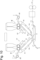
- FIG. 10 is a schematic layout diagram of a manufacturing apparatus for manufacturing an absorbent body
- FIG. 11 is an enlarged cross-sectional view of a relevant part.
- this apparatus is provided with: two units U1 and U2 including conveyers C1 and C2 and sprayers 111 and 112, respectively; and a laminating roller R.
- the conveyers C1 and C2 each have a negative pressure case 119, and convey sheets S1 and S2 while sucking them.
- the sheets S1 and S2 each have a diffusion layer 121 and a short fiber layer 122, and the short fiber layer 122 is napped by a napping roller 130.
- the sprayers 111 and 112 spray a powder and granular material 120 as the absorbent material to the napped upper surfaces of the sheet S1 and S2 being conveyed along inclined surfaces F1 and F2.
- the laminating roller R places the sheets S1 and S2 one on another so that the absorbent layers L1 and L2 face each other (for example, see Patent Literature 1).
- Patent Literature 2 discloses to manufacture an absorbent body by placing one on another two sheets having an absorbent material transferred thereto.
- a problem to be solved by the present invention is to provide an absorbent body manufacturing method capable of increasing variations of the absorbent body.
- the present invention provides an absorbent body manufacturing method structured as follows:
- An absorbent body manufacturing method is provided with: (i) a first step of forming a first absorbent sheet having a first absorbent material disposed in first regions of a first sheet; (ii) a second step of forming a second absorbent sheet having a second absorbent material disposed in second regions of a second sheet; (iii) a third step of forming a continuous body including the first absorbent sheet and the second absorbent sheet and in which the first regions and the second regions are adjacent to each other in plan view; and (iv) a fourth step of forming an absorbent body including the first absorbent material and the second absorbent material, by cutting the continuous body so that the first regions and the second regions adjacent to each other are included.
- the continuous body is formed in which the first absorbent sheet and the second absorbent sheet overlap each other such that the first regions and the second regions are adjacent to each other in plan view.
- the overlapping first and second absorbent sheets are simultaneously cut at the fourth step to form the absorbent body.
- An absorbent body manufacturing method of another preferred mode is further provided with: (v) a fifth step of forming first pieces including the first regions, by cutting the first absorbent sheet after the first step and before the third step; and (vi) a sixth step of forming second pieces including the second region, by cutting the second absorbent sheet after the second step and before the third step.
- the continuous body is formed in which the first pieces and the second pieces are aligned such that the first regions and the second regions are adjacent to each other in plan view.
- the continuous body includes the first and second absorbent sheets being cut and the first and second pieces that are the first and second absorbent sheets being cut do not overlap each other, the thickness of the absorbent body can be reduced, and the sheet materials used for the absorbent body can be reduced.
- the first absorbent material is disposed on more than one of the first sheets.
- the continuous body is formed in which more than one of the first sheets is arranged with a spacing therebetween.
- a channel can be formed along the spacing between the adjoining first sheets.
- an absorbent body can be formed that easily follows the shape of the wearing part.
- the first absorbent material is disposed in the first regions aligned in a direction in which the first sheet continues, in a plurality of rows with a spacing therebetween.
- the second absorbent material is disposed in the second regions aligned in a direction in which the second sheet continues, with a spacing therebetween.
- a channel can be formed between a plurality of rows of the first regions aligned in the direction in which the first sheet continues.
- a first coating sheet is joined with the first sheet to form the first absorbent sheet having the first absorbent material disposed between the first sheet and the first coating sheet.
- variations of the absorbent body can be increased. Moreover, the movement of the first absorbent material toward the outside of the first regions can be suppressed, so that the quality of the absorbent body is stabilized.
- the second coating sheet is joined with the second sheet to form the second absorbent sheet having the second absorbent material disposed between the second sheet and the second coating sheet.
- variations of the absorbent body can be increased.
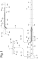
- FIG. 1 is an explanatory view showing the outline of the method for manufacturing an absorbent body 10. As shown in FIG. 1 , a first absorbent sheet 30 and a second absorbent sheet 20 are formed, a continuous body 14 is formed in which the first and second absorbent sheets 30 and 20 overlap each other, and then, the continuous body 14 is cut to form the absorbent body 10.
- slits 32p and 32q passing between principal surfaces 32s and 32t of the raw sheet 32 are formed to divide the raw sheet 32, thereby forming a plurality of first sheets 32a, 32b and 32c. Then, the spacings 32u and 32v between the adjoining first sheets 32a, 32b and 32c are increased, and the first sheets 32a to 32c are conveyed parallel to one another.
- a first absorbent material 33 (see FIG. 3(b) ) is intermittently supplied to the first sheets 32a to 32c and/or the first coating sheet 34, and then, the first sheets 32a to 32c and the first coating sheet 34 are joined together to form the first absorbent sheet 30 having the first absorbent material 33 disposed.
- the first absorbent material 33 is an absorbent material that is granular or powdery in dry state, and is, for example, a powder and granular material of a superabsorbent polymer, abbreviated as "SAP".
- the first absorbent sheet 30 can be formed, for example, by using the manufacturing apparatus of FIG. 10 .
- the first sheets 32a to 32c are conveyed by using one of the conveyers C1 and C2, and the first coating sheet 34 is conveyed by using the other thereof.
- the first absorbent material 33 is sprayed to the upper surface of the first sheets 32a to 32c and/or the first coating sheet 34 being conveyed along the inclined surfaces F1 and F2, and then, by using the laminating roller R, the first sheets 32a to 32c and the first coating sheet 34 are joined together.
- the first absorbent sheet 30 can be formed without using the napping roller 130, the first sheets 32a to 32c may be napped by using the napping roller 130.
- Hot melt or adhesive is previously applied to the first coating sheet 34 and/or the first sheets 32a and 32c by using an application device 81, and the first absorbent sheet 30 is formed where the first sheets 32a to 32c and the first coating sheet 34 are bonded together.
- the first absorbent sheet 30 may be formed where the bonding between the first sheets 32a and 32c and the first coating sheet 34 is omitted.
- the first absorbent material 33 is supplied to the first sheets 32a to 32c and/or the first coating sheet 34 so as to form the first absorbent sheet 30 having the first absorbent material 33 disposed in hatched first regions 33a to 33c of the first sheets 32a to 32c shown in FIG. 2(a) .
- the first regions 33a to 33c are aligned in the direction 32X in which the first sheets 32a to 32c continue, in a plurality of rows with a spacing therebetween. While the first absorbent material 33 is supplied at appropriate times at appropriate positions, it is preferable to supply it immediately before the first sheets 32a to 32c and the first coating sheet 34 are joined together because the disturbance of the supply pattern of the first absorbent material 33 can be suppressed.
- the first regions 33a to 33c may be designed as appropriate; for example, they may be aligned in the direction 32x in which the first sheets 32a to 32c continue, or may continue without any spacing therebetween in the direction 32x in which the first sheets 32a to 32c continue. While the first regions 33a to 33c may intersect with a cutting position 11 where the continuous body 14 is to be cut to form the absorbent body 10, wear of the cutting blade can be suppressed if they are away from the cutting position 11 as shown in FIG. 2(a) .
- first sheets 32a to 32c instead of dividing a plurality of first sheets 32a to 32c from the raw sheet 32, a plurality of first sheets 32a to 32c prepared in advance may be used.
- the number of first sheets 32a to 32c may be one, two, or four or more.
- the first absorbent sheet 30 may be formed where the first absorbent material 33 is disposed on the first sheets 32a to 32c. In this case, the spacings 32u and 32v between the first sheets 32a to 32c may be increased after the first absorbent material 33 is disposed on more than one of the first sheets 32a to 32c.
- the method for manufacturing the absorbent body 10 is provided with a first step of forming the first absorbent sheet 30 having the first absorbent material 33 disposed in the first regions 33a to 33c of at least one of the first sheets 32a to 32c.
- the first absorbent material 33 is disposed on more than one of the first sheets 32a to 32c.
- the first absorbent material 33 is disposed in the first regions 33a to 33c aligned in the direction 32x in which the first sheets 32a to 32c continue, in a plurality of rows with a spacing therebetween.
- the first coating sheet 34 is joined with the first sheets 32a to 32c to form the first absorbent sheet 30 having the first absorbent material 33 disposed between the first sheets 32a to 32c and the first coating sheet 34.
- FIG. 2(b) is an explanatory view of a second sheet 22.
- the second sheet 22 is conveyed in a direction 22x in which the second sheet 22 continues, and a second coating sheet 24 is conveyed in a direction 24x in which the second coating sheet 24 continues.
- the second sheet 22 and the second coating sheet 24 are nonwoven fabric.
- a second absorbent material 23 (see FIG. 3(b) ) is intermittently supplied to the second sheet 22 and/or the second coating sheet 24. Then, the second sheet 22 and the second coating sheet 24 are joined together to form the second absorbent sheet 20. Like the first absorbent sheet 30, the second absorbent sheet 20 can be formed, for example, by using the manufacturing apparatus of FIG. 10 .
- the second absorbent material 23 is an absorbent material that is granular or powdery in dry state, is, for example, a powder and granular material of SAP, and may be the same as or different from the first absorbent material 33.
- Hot melt or adhesive is previously applied to the second sheet 22 and/or the second coating sheet 24 by using an application device 82, and the second absorbent sheet 20 is formed where the second sheet 22 and the second coating sheet 24 are bonded together.
- the second absorbent sheet 20 may be formed where the bonding between the second sheet 22 and the second coating sheet 24 is omitted.
- the second absorbent material 23 is supplied to the second sheet 22 and/or the second coating sheet 24 so as to form the second absorbent sheet 20 having the second absorbent material 23 disposed in hatched second regions 23a and 23b of the second sheet 22 shown in FIG. 2(b) .
- the second regions 23a and 23b are aligned in a row in the direction 22x in which the second sheet 22 continues, with a spacing therebetween. While the second absorbent material 23 is supplied at appropriate times at appropriate positions, it is preferable to supply it immediately before the second sheet 22 and the second coating sheet 24 are joined together because the disturbance of the supply pattern of the second absorbent material 23 can be suppressed.
- the second absorbent material 23 may be designed as appropriate; for example, it may continue without any spacing, in the direction 22x in which the second sheet 22 continues. While the second regions 23a and 23b may intersect with the cutting position 11 where the continuous body 14 is to be cut to form the absorbent body 10, wear of the sheet cutting blade can be suppressed if they are away from the cutting position 11 as shown in FIG. 2(b) .
- the second absorbent sheet 20 may be formed where the second absorbent material 23 is disposed on the second sheet 22.
- An example of this structure will be described later as a fourth embodiment.
- the method for manufacturing the absorbent body 10 is provided with a second step of forming the second absorbent sheet 20 having the second absorbent material 23 disposed in the second regions 23a and 23b of the second sheet 22.
- the second absorbent material 23 is disposed in the second regions 23a and 23b aligned with a spacing therebetween, in the direction 22x in which the second sheet 22 continues.
- the second coating sheet 24 is joined with the second sheet 22 to form the second absorbent sheet 20 having the second absorbent material 23 disposed between the second sheet 22 and the second coating sheet 24.
- FIG. 3(a) is a schematic plan view showing the continuous body 14 in perspective and a schematic plan view of the absorbent body 10.
- FIG. 3(b) is a schematic cross-sectional view taken on the line A-A of FIG. 3(a) .
- a carrier sheet 12 is conveyed in a direction 12x in which the carrier sheet 12 continues, and hot melt or adhesive is applied to the first and second absorbent sheets 30 and 20 by using application devices 83 and 84.
- the second absorbent sheet 20 is placed on an intermediate region in the width direction of one principal surface 12s of the carrier sheet 12, and the second absorbent sheet 20 is pasted to the carrier sheet 12.
- the first absorbent sheet 30 is placed on the second absorbent sheet 20, and the first absorbent sheet 30 is pasted to the second absorbent sheet 20.
- the first and second absorbent sheets 30 and 20 are placed one on another so that the first regions 33a to 33c in which the first absorbent material 33 is disposed on the first absorbent sheet 30 and the second regions 23a and 23b in which the second absorbent material 23 is disposed on the second absorbent sheet 20 are adjacent to each other in plan view, and the first regions 33a to 33c and the second regions 23a and 23b adjacent to each other are arranged between the adjoining cutting positions 11.
- hot melt or adhesive is applied to the carrier sheet 12 and/or the first absorbent sheet 30 by using an application device 85, and then, parts 12a and 12b of the carrier sheet 12 protruding on both sides of the first and second adhesive sheets 30 and 20 are folded and placed on the first absorbent sheet 30. Thereby, the continuous body 14 has the first and second absorbent sheets 30 and 20 wrapped by the carrier sheet 12.
- the continuous body 14 is cut at the cutting positions 11 to form the absorbent body 10.
- the absorbent body 10 can be formed in which the first and second absorbent materials 23 and 33 are disposed.
- Some or all of the application apparatuses 81 to 85 may be omitted. Appropriate parts may be bonded at appropriate times by ultrasonic waves, heat sealing or the like instead of adhesive bonding.
- the first and/or second absorbent sheets 30 and 20 and the continuous body 14 may be formed with adhesive bonding or adhesive-free bonding omitted.
- the order in which the carrier sheet 12 and the first and second absorbent sheets 30 and 20 are placed one on another is arbitrary.
- the order may be as follows: The second absorbent sheet 20 is placed on the carrier sheet 12, and then, the first absorbent sheet 30 is placed on the second absorbent sheet 20. After the first and second absorbent sheets 30 and 20 are placed one on another, the first and second absorbent sheets 30 and 20 are placed on the carrier sheet 12. Further, the continuous body 14 may be formed in which the carrier sheet 12 is omitted and the first and second absorbent sheets 30 and 20 overlap each other.
- the method for manufacturing the absorbent body 10 is provided with: a third step of forming the continuous body 14 including the first absorbent sheet 30 and the second absorbent sheet 20 and in which the first regions 33a to 33c and the second regions 23a and 23b are adjacent to each other in plan view; and a fourth step of forming the absorbent body 10 including the first absorbent material 33 and the second absorbent material 23, by cutting the continuous body 14 so that the first regions 33a to 33c and the second regions 23a and 23b adjacent to each other are included.
- the continuous body 14 is formed in which the first absorbent sheet 30 and the second absorbent sheet 20 overlap each other such that the first regions 33a to 33c and the second regions 23a and 23b are adjacent to each other in plan view.
- the overlapping first and second absorbent sheets 30 and 20 are simultaneously cut at the fourth step to form the absorbent body.
- the continuous body 14 is formed in which more than one of the first sheets 32a to 32c is arranged with a spacing therebetween.
- FIG. 4 is a relevant part perspective view of the continuous body 14 in which the first and second absorbent sheets 30 and 20 overlap each other, and show the first and second regions arranged between the adjoining cutting positions 11.
- the first and second absorbent sheets 30 and 20 continue in a first direction X.
- FIG. 4(a) is the same disposition pattern as that of FIGS. 1 to 3 .
- the three first regions 33a to 33c extending in the first direction X are arranged between the two second regions 23a and 23b arranged with a spacing therebetween in the first direction X, and the first regions 33a to 33c are in contact with the two second regions 23a and 23b.
- the three first regions 33a to 33c are arranged with a spacing therebetween in a second direction Y orthogonal to the first direction X.
- This forms two channels 16a surrounded by the first and second regions 33a to 33c, and 23a and 23b.
- the first and second absorbent materials 33 and 22 are not disposed in the two channels 16a.
- the three first regions 33a, 33d and 33c extending in the first direction X are arranged between the two second regions 23a and 23b arranged with a spacing therebetween in the first direction X.
- the first regions 33a and 33c on both side in the second direction Y are in contact with the two second regions 23a and 23b, and the central first region 33d is in contact with only one second region 23b and adjoins the other second region 23a with a spacing therebetween. This forms one U-shaped channel 16b.
- three first regions 33p to 33r extending in the first direction X are arranged between the two second regions 23a and 23b arranged with a spacing therebetween in the first direction X, and the three first regions 33p to 33r each adjoin the one second region 23a with a spacing therebetween and are in contact with the other second region 23b.
- three first regions 33u to 33w extending in the first direction X are arranged between the two second regions 23a and 23b arranged with a spacing therebetween in the first direction X, and the three first regions 33u to 33w each adjoin the two second regions 23a and 23b with a spacing from the two second regions 23a and 23b.
- two first regions 33m and 33n extending in the first direction X are arranged with a spacing therebetween in the second direction Y
- three second regions 23u to 23w are arranged with a spacing therebetween in the first direction X between the two first regions 33m and 33n
- the three second regions 23u to 23w each adjoin the two first regions 33m and 33n.
- the disposition pattern is possible in which the first regions and the second regions shown in FIG. 4 are interchanged.
- the absorbent body By forming the absorbent body by the above-described method, it is possible to change the characteristics of the absorbent body according to the pattern of the first and second regions and the kind and amount of the first and second absorbent materials disposed in the first and second regions. Consequently, variations of the absorbent body can be increased.
- the absorbent body 10 When the absorbent body 10 includes a plurality of first sheets 32a and 32c, a channel can be formed along the spacings 32u and 32v between the adjoining first sheets 32a to 32c. Moreover, because the plural first sheets 32a to 32c are not restrained by one another, an absorbent body 10 can be formed that easily follows the shape of the wearing part.
- the first coating sheet 34 By adding the first coating sheet 34, the movement of the first absorbent material 33 toward the outside of the first regions 33a and 33b is suppressed by the first coating sheet 34, so that the quality of the absorbent body 10 is stabilized.
- the second coating sheet 24 By adding the second coating sheet 24, the movement of the second absorbent material 23 toward the outside of the second regions 23a and 23b is suppressed by the second coating sheet 24, so that the quality of the absorbent body 10 is stabilized.
- various characteristics such as liquid permeability, liquid diffusibility and liquid retainability of the first and/or second coating sheets 33 and 23, variations of the absorbent body 10 can be increased.
- FIG. 5 is an explanatory view showing the outline of the method for manufacturing the absorbent body 10a.
- the same parts as those of the first embodiment are denoted by the same reference designations and differences from the first embodiment will mainly be described.
- the absorbent body manufacturing method of the second embodiment is substantially similar to that of the first embodiment.
- a raw sheet 42 is conveyed in a direction 42x in which the raw sheet 42 continues, and the raw sheet 42 is divided into first and third divisional sheets 52 and 62.
- the first divisional sheet 52 is conveyed in a direction 52x in which the first divisional sheet 52 continues, and a first coating sheet 54 is conveyed in a direction 54x in which the first coating sheet 54 continues.
- the first divisional sheet 52 is divided to form a plurality of first sheets 52a to 52c.
- the first absorbent material is supplied to the first sheets 52a to 52c and/or the first coating sheet 54.
- first sheets 52a to 52c and the first coating sheet 54 are joined together to form a first absorbent sheet 50 where the first absorbent material is sandwiched between the first sheets 52a to 52c and the first coating sheet 54 and the first absorbent material is disposed in first regions of the first sheets 52a to 52c.
- the third divisional sheet 62 is conveyed in a direction 62x in which the third divisional sheet 62 continues, and a third coating sheet 64 is conveyed in a direction 64x in which the third coating sheet 64 continues. Then, the third divisional sheet 62 is divided to form a plurality of third sheets 62a to 62c. Then, as indicated by the arrow 63x, a third absorbent material is supplied to the third sheets 62a to 62c and/or the third coating sheet 64.
- the third sheets 62a to 62c and the third coating sheet 64 are joined together to form a third absorbent sheet 60 where the third absorbent material 63 is sandwiched between the third sheets 62a to 62c and the third coating sheet 64 and the third absorbent material is disposed in third regions of the third sheet 60.
- a fourth absorbent material is supplied to the first absorbent sheet 50 and/or the third absorbent sheet 60. Then, the first and third absorbent sheets 50 and 60 are joined together to form a fourth absorbent sheet 40 where the fourth absorbent material is sandwiched between the first absorbent sheet 50 and the third absorbent sheet 60 and the fourth absorbent material is disposed in fourth regions.
- the second sheet 22 is conveyed in the direction 22x in which the second sheet 22 continues
- the second coating sheet 24 is conveyed in the direction 24x in which the second coating sheet 24 continues
- the second absorbent material is supplied to the second sheet 22 and/or the second coating sheet 24 as indicated by the arrow 23x
- the second sheet 22 and the second coating sheet 24 are joined together to form the second absorbent sheet 20 where the second absorbent material is sandwiched between the second sheet 22 and the second coating sheet 24 and the second absorbent material is disposed in the second regions of the second sheet 22.
- the second absorbent sheet 20 is placed on the carrier sheet 12, and then, the fourth absorbent sheet 40 is placed on the second absorbent sheet 20.
- the continuous body 14a may be formed so that none of the first to fourth regions overlaps the other regions in plan view. Then, both side parts 12a and 12b of the carrier sheet 12 in the width direction are folded. Thereby, the second absorbent sheet 20 and the fourth absorbent sheet 40 are wrapped by the carrier sheet 12.
- the continuous body 14a is cut to form the absorbent body 10a.
- the absorbent body 10a including at least two of the first to fourth absorbent materials is formed by cutting the continuous body 14a at the cutting positions 11 so that at least two adjoining regions are included between the adjoining cutting positions 11.
- the sheets are bonded as appropriate by applying hot melt or adhesive by using the application devices 81 to 87.
- Appropriate parts may be bonded at appropriate times by ultrasonic waves, heat sealing or the like instead of adhesive bonding.
- the first to fourth absorbent sheets 50, 20, 60 and 40 and the continuous body 14a may be formed with adhesive bonding or adhesive-free bonding omitted.
- the absorbent body 10a compared with the first embodiment, the kind and amount of the absorbent materials and the number of sheets can be increased. Consequently, variations of the absorbent body can be increased.
- first to third coating sheets 54, 24 and 64 may be omitted.
- the number of first and/or third sheets 52a to 52c and 62a to 63c may be one, two, or four or more.
- the continuous body 14 may be formed in which the second and fourth absorbent sheets 20 and 40 overlap each other with the carrier sheet 12 omitted.
- FIG. 6 is an explanatory view of the method for manufacturing the absorbent body 10b of the third embodiment.
- FIG. 7(a) is a schematic plan view of the continuous body 14b and the absorbent body 10b.
- FIG. 7(b) is a schematic cross-sectional view taken on the line B-B of FIG. 7(a) .
- the first absorbent sheet 30 where the first absorbent material 33 is sandwiched between the first sheets 32a to 32c and the first coating sheet 34 and the first absorbent material 33 is disposed in the first regions 33a to 33c of the first sheets 32a to 32c; and the second absorbent sheet 20 where the second absorbent material 23 is sandwiched between the second sheet 22 and the second coating sheet 24 and the second absorbent material 23 is disposed in the second regions 23a and 23b of the second sheet 22.
- the first absorbent sheet 30 is cut to form first pieces 31 including the first regions 33a to 33c and the first absorbent material 33.
- the second absorbent sheet 20 is cut to form second pieces 21 including the second regions 23a and 23b and the second absorbent material 23.
- hot melt or adhesive is applied to one principal surface 12s of the carrier sheet 12 by using an application device 88, and then, the second pieces 21 are pasted to a central region of the carrier sheet 12 with a predetermined spacing. Then, the first pieces 31 are pasted to the regions between the second pieces 21 of the carrier sheet 12. This forms the continuous body 14b including the first pieces 31 and the second pieces 21. At this time, the first pieces 31 and the second pieces 21 are aligned such that the first regions 31 and the second regions 21 are adjacent to each other in plan view.
- parts 12a and 12b of the carrier sheet 12 on both sides in the width direction are folded and placed on the first absorbent sheet 30, so that the first pieces 31 and the second pieces 21 are wrapped by the carrier sheet 12.
- the continuous body 14b is cut at the cutting positions 11 to form the absorbent body 10b.
- the absorbent body 10b can be formed in which the first pieces 31 of the first absorbent sheet 30 and the second pieces 21 of the second absorbent sheet 20 are arranged.
- the method for manufacturing the absorbent body 10b of the third embodiment is provided with: a first step of forming the first absorbent sheet 30 having the first absorbent material 33 disposed in the first regions 33a to 33c of at least one of the first sheets 32a to 32c; a second step of forming the second absorbent sheet 20 having the second absorbent material 23 disposed in the second regions 23a and 23b of the second sheet 22; a third step of forming the continuous body 14b including the first absorbent sheet 30 and the second absorbent sheet 20 and in which the first regions 33a to 33c and the second regions 23a and 23b are adjacent to each other in plan view; and a fourth step of forming the absorbent body 10b including the first absorbent material 33 and the second absorbent material 23 by cutting the continuous body 14b so that the first regions 33a to 33c and the second regions 23a and 23b adjacent to each other are included.
- the method of the third embodiment is further provided with: a fifth step of forming the first pieces 31 including the first regions 33a to 33c, by cutting the first absorbent sheet 30 after the first step and before the third step; and a sixth step of forming the second pieces 21 including the second regions 23a and 23b, by cutting the second absorbent sheet 20 after the second step and before the third step.
- the continuous body 14b is formed in which the first pieces 31 and the second pieces 21 are aligned such that the first regions 33a to 33c and the second regions 23a and 23b are adjacent to each other in plan view.
- the first absorbent material 33 is disposed on more than one of the first sheets 32a to 32c.
- the continuous body 14 is formed in which more than one the first sheets 32a to 32c is arranged with a spacing therebetween.
- the first absorbent material 33 is disposed in the first regions 33a to 33c aligned in the direction 32x in which the first sheets 32a to 32c continue, in a plurality of rows with a spacing therebetween.
- the second absorbent material 23 is disposed in the second regions 22a and 22b aligned in the direction 22x in which the second sheet 22 continues, with a spacing therebetween.
- the first coating sheet 34 is joined with the first sheets 32a to 32c to form the first absorbent sheet 30 having the first absorbent material 33 disposed between the first sheets 32a to 32c and the first coating sheet 34.
- the second coating sheet 24 is joined with the second sheet 22 to form the second absorbent sheet 20 having the second absorbent material 23 disposed between the second sheet 22 and the second coating sheet 24.
- the absorbent body manufacturing method of the third embodiment since the continuous body 14b is formed in which the first and second absorbent sheets 30 and 20 do not overlap each other, compared with the first embodiment, the thickness of the absorbent body 10b can be reduced, and the sheet materials used for the absorbent body 10b can be reduced.
- FIGS. 8 and 9 An absorbent body manufacturing method of a fourth embodiment will be described with reference to FIGS. 8 and 9 .
- an absorbent body 10c is manufactured with the second coating sheet 24 of the first embodiment omitted.
- FIG. 8 is an explanatory view showing the outline of the method for manufacturing the absorbent body 10c.
- FIG. 9(a) is a schematic plan view of a continuous body 14c and the absorbent body 10c
- FIG. 9(b) is a schematic cross-sectional view taken on the line C-C of FIG. 9(a) .
- the first absorbent sheet 30 is formed where the first absorbent material 33 is sandwiched between the first sheets 32a to 32c and the first coating sheet 34 and the first absorbent material 33 is disposed in the first regions 33a to 33c of the first sheets 32a to 32c.
- the second absorbent sheet 20a is formed in a similar manner to that of the first embodiment by using the carrier sheet 12 instead of the second coating sheet 24 of the first embodiment. That is, the second sheet 22 is conveyed in the direction 22x in which the second sheet 22 continues, and the carrier sheet 12 wider than the second sheet 22 is conveyed in the direction 12x in which the carrier sheet 12 continues. Then, as indicated by the arrow 23x in FIG. 8 , the second absorbent material 23 is intermittently supplied to the second sheet 22 and/or the carrier sheet 12. Then, the second sheet 22 is placed on a central region in the width direction of one principal surface 12s of the carrier sheet 12 to form the second absorbent sheet 20a. This forms the second absorbent sheet 20a where the second absorbent material 23 is sandwiched between the second sheet 22 and the carrier sheet 12 and the second absorbent material 23 is disposed in the second regions 23a and 23b of the second sheet 22.
- the second absorbent sheet 20a is conveyed in a direction 20x in which the second absorbent sheet 20a continues.
- the first absorbent sheet 30 having hot melt or adhesive applied thereto by using the application device 83 is pasted to the second absorbent sheet 20a so as to overlap the second sheet 22 of the second absorbent sheet 20a. This forms the continuous body 14c including the first absorbent sheet 30 and the second absorbent sheet 20a.
- the first and second absorbent sheets 30 and 20a are placed one on another so that the first regions 33a to 33c having the first absorbent material 33 disposed on the first absorbent sheet 30 and the second regions 23a and 23b having the second absorbent material 23 disposed on the second absorbent sheet 20a are adjacent to each other in plan view, to make the first regions 33a to 33c and the second regions 23a and 23c arranged between the adjoining cutting positions 11.
- the continuous body 14c has the first and second absorbent sheets 30 and 20a wrapped by the carrier sheet 12.
- the continuous body 14c is cut at the cutting positions 11 to form the absorbent body 10c.
- the absorbent body 10c can be formed in which the first and second absorbent materials 23 and 33 are disposed.
- Some or all of the application apparatuses 81 to 83 and 85 may be omitted. Appropriate parts may be bonded at appropriate times by ultrasonic waves, heat sealing or the like instead of adhesive bonding.
- the first and/or second absorbent sheets 30 and 20a and the continuous body 14c may be formed with adhesive bonding or adhesive-free bonding omitted.
- variations of the absorbent body 10c can be increased by omitting the second coating sheet 24. Moreover, the materials used for manufacturing the absorbent body 10c can be reduced.
- the first to fourth sheets may be other than nonwoven fabric.
- the absorbent body may be formed by forming the continuous body by cutting either one of the first and second absorbent sheets into pieces without cutting the other one thereof into pieces and then, cutting the continuous body.
Landscapes
- Health & Medical Sciences (AREA)
- Engineering & Computer Science (AREA)
- Life Sciences & Earth Sciences (AREA)
- Biomedical Technology (AREA)
- Heart & Thoracic Surgery (AREA)
- Vascular Medicine (AREA)
- Epidemiology (AREA)
- Animal Behavior & Ethology (AREA)
- General Health & Medical Sciences (AREA)
- Public Health (AREA)
- Veterinary Medicine (AREA)
- Manufacturing & Machinery (AREA)
- Mechanical Engineering (AREA)
- Absorbent Articles And Supports Therefor (AREA)
Abstract
Description
- The present invention relates to a method for manufacturing an absorbent body including an absorbent material.
- An absorbent body containing an absorbent material is used for diapers and sanitary napkins. For example,
FIG. 10 is a schematic layout diagram of a manufacturing apparatus for manufacturing an absorbent body, andFIG. 11 is an enlarged cross-sectional view of a relevant part. As shown inFIGS. 10 and11 , this apparatus is provided with: two units U1 and U2 including conveyers C1 and C2 andsprayers negative pressure case 119, and convey sheets S1 and S2 while sucking them. The sheets S1 and S2 each have adiffusion layer 121 and ashort fiber layer 122, and theshort fiber layer 122 is napped by anapping roller 130. Thesprayers granular material 120 as the absorbent material to the napped upper surfaces of the sheet S1 and S2 being conveyed along inclined surfaces F1 and F2. This forms absorbent layers L1 and L2 on theshort fiber layers 122 of the sheets S1 and S2. The laminating roller R places the sheets S1 and S2 one on another so that the absorbent layers L1 and L2 face each other (for example, see Patent Literature 1). -
Patent Literature 2 discloses to manufacture an absorbent body by placing one on another two sheets having an absorbent material transferred thereto. -
- [Patent Literature 1]
WO 2021/015001 A1 - [Patent Literature 2]
WO 2015/123087 A1 - Merely placing two sheets one on another and disposing an absorbent material between the two sheets as described above limits variations of the absorbent body. For this reason, it is desired to further increase variations of the absorbent body.
- In view of such circumstances, a problem to be solved by the present invention is to provide an absorbent body manufacturing method capable of increasing variations of the absorbent body.
- To solve the above-mentioned problem, the present invention provides an absorbent body manufacturing method structured as follows:
- An absorbent body manufacturing method is provided with: (i) a first step of forming a first absorbent sheet having a first absorbent material disposed in first regions of a first sheet; (ii) a second step of forming a second absorbent sheet having a second absorbent material disposed in second regions of a second sheet; (iii) a third step of forming a continuous body including the first absorbent sheet and the second absorbent sheet and in which the first regions and the second regions are adjacent to each other in plan view; and (iv) a fourth step of forming an absorbent body including the first absorbent material and the second absorbent material, by cutting the continuous body so that the first regions and the second regions adjacent to each other are included.
- According to the above-described method, it is possible to change the characteristics of the absorbent body according to the pattern of the first and second regions and the kind and amount of the first and second absorbent materials disposed in the first and second regions. Consequently, variations of the absorbent body can be increased.
- In an absorbent body manufacturing method of a preferred mode, at the third step, the continuous body is formed in which the first absorbent sheet and the second absorbent sheet overlap each other such that the first regions and the second regions are adjacent to each other in plan view.
- In this case, the overlapping first and second absorbent sheets are simultaneously cut at the fourth step to form the absorbent body.
- An absorbent body manufacturing method of another preferred mode is further provided with: (v) a fifth step of forming first pieces including the first regions, by cutting the first absorbent sheet after the first step and before the third step; and (vi) a sixth step of forming second pieces including the second region, by cutting the second absorbent sheet after the second step and before the third step. At the third step, the continuous body is formed in which the first pieces and the second pieces are aligned such that the first regions and the second regions are adjacent to each other in plan view.
- In this case, since the continuous body includes the first and second absorbent sheets being cut and the first and second pieces that are the first and second absorbent sheets being cut do not overlap each other, the thickness of the absorbent body can be reduced, and the sheet materials used for the absorbent body can be reduced.
- Preferably, at the first step, the first absorbent material is disposed on more than one of the first sheets. At the third step, the continuous body is formed in which more than one of the first sheets is arranged with a spacing therebetween.
- In this case, a channel can be formed along the spacing between the adjoining first sheets. Moreover, because the plural first sheets are not restrained by one another, an absorbent body can be formed that easily follows the shape of the wearing part.
- Preferably, at the first step, the first absorbent material is disposed in the first regions aligned in a direction in which the first sheet continues, in a plurality of rows with a spacing therebetween. At the second step, the second absorbent material is disposed in the second regions aligned in a direction in which the second sheet continues, with a spacing therebetween.
- In this case, a channel can be formed between a plurality of rows of the first regions aligned in the direction in which the first sheet continues.
- Preferably, at the first step, a first coating sheet is joined with the first sheet to form the first absorbent sheet having the first absorbent material disposed between the first sheet and the first coating sheet.
- In this case, by adding the first coating sheet, variations of the absorbent body can be increased. Moreover, the movement of the first absorbent material toward the outside of the first regions can be suppressed, so that the quality of the absorbent body is stabilized.
- Preferably, at the second step, the second coating sheet is joined with the second sheet to form the second absorbent sheet having the second absorbent material disposed between the second sheet and the second coating sheet.
- In this case, by adding the second coating sheet, variations of the absorbent body can be increased. Moreover, the movement of the second absorbent material toward the outside of the second regions can be suppressed, so that the quality of the absorbent body is stabilized.
- According to the present invention, variations of the absorbent body can be increased.
-
- [
Figure 1] FIG. 1 is an explanatory view of an absorbent body manufacturing method (first embodiment). - [
Figure 2] FIG. 2(a) is an explanatory view of first sheets andFIG. 2(b) is an explanatory view of a second sheet (first embodiment). - [
Figure 3] FIG. 3(a) is a schematic plan view of a continuous body and an absorbent body andFIG. 3(b) is a schematic cross-sectional view of the continuous body and the absorbent body (first embodiment). - [
Figure 4] FIG. 4 is a relevant part perspective view of the continuous body (first embodiment). - [
Figure 5] FIG. 5 is an explanatory view of an absorbent body manufacturing method (second embodiment). - [
Figure 6] FIG. 6 is an explanatory view of an absorbent body manufacturing method (third embodiment). - [
Figure 7] FIG. 7(a) is a schematic plan view of a continuous body and an absorbent body andFIG. 7(b) is a schematic cross-sectional view of the continuous body and the absorbent body (third embodiment). - [
Figure 8] FIG. 8 is an explanatory view of an absorbent body manufacturing method (fourth embodiment). - [
Figure 9] FIG. 9(a) is a schematic plan view of a continuous body and an absorbent body andFIG. 9(b) is a schematic cross-sectional view of the continuous body and the absorbent body (fourth embodiment). - [
Figure 10] FIG. 10 is the schematic layout diagram of the absorbent body manufacturing apparatus (first conventional example). - [
Figure 11] FIG. 11 is the enlarged cross-sectional view of the relevant part of the absorbent body manufacturing apparatus (first conventional example). - Hereinafter, embodiments of the present invention will be described with reference to the drawings.
- [First embodiment] An absorbent body manufacturing method of a first embodiment will be described with reference to
FIGS. 1 to 4 . -
FIG. 1 is an explanatory view showing the outline of the method for manufacturing anabsorbent body 10. As shown inFIG. 1 , a firstabsorbent sheet 30 and a secondabsorbent sheet 20 are formed, acontinuous body 14 is formed in which the first and secondabsorbent sheets continuous body 14 is cut to form theabsorbent body 10. -
- (1) The first
absorbent sheet 30 is formed as follows:FIG. 2(a) is an explanatory view offirst sheets 32a to 32c. As shown inFIGS. 1 and2(a) , araw sheet 32 is conveyed in adirection 32x in which theraw sheet 32 continues, and afirst coating sheet 34 is conveyed in adirection 34x in which thefirst coating sheet 34 continues. For example, theraw sheet 32 is air-laid nonwoven fabric, and thefirst coating sheet 34 is nonwoven fabric. - Then, slits 32p and 32q passing between
principal surfaces raw sheet 32 are formed to divide theraw sheet 32, thereby forming a plurality offirst sheets spacings first sheets first sheets 32a to 32c are conveyed parallel to one another. - Then, as indicated by the
arrow 33x inFIG. 1 , a first absorbent material 33 (seeFIG. 3(b) ) is intermittently supplied to thefirst sheets 32a to 32c and/or thefirst coating sheet 34, and then, thefirst sheets 32a to 32c and thefirst coating sheet 34 are joined together to form the firstabsorbent sheet 30 having the firstabsorbent material 33 disposed. The firstabsorbent material 33 is an absorbent material that is granular or powdery in dry state, and is, for example, a powder and granular material of a superabsorbent polymer, abbreviated as "SAP". - The first
absorbent sheet 30 can be formed, for example, by using the manufacturing apparatus ofFIG. 10 . In this case, thefirst sheets 32a to 32c are conveyed by using one of the conveyers C1 and C2, and thefirst coating sheet 34 is conveyed by using the other thereof. By using either one or both of thesprayers absorbent material 33 is sprayed to the upper surface of thefirst sheets 32a to 32c and/or thefirst coating sheet 34 being conveyed along the inclined surfaces F1 and F2, and then, by using the laminating roller R, thefirst sheets 32a to 32c and thefirst coating sheet 34 are joined together. While the firstabsorbent sheet 30 can be formed without using the nappingroller 130, thefirst sheets 32a to 32c may be napped by using the nappingroller 130. - Hot melt or adhesive is previously applied to the
first coating sheet 34 and/or thefirst sheets application device 81, and the firstabsorbent sheet 30 is formed where thefirst sheets 32a to 32c and thefirst coating sheet 34 are bonded together. The firstabsorbent sheet 30 may be formed where the bonding between thefirst sheets first coating sheet 34 is omitted. - The first
absorbent material 33 is supplied to thefirst sheets 32a to 32c and/or thefirst coating sheet 34 so as to form the firstabsorbent sheet 30 having the firstabsorbent material 33 disposed in hatchedfirst regions 33a to 33c of thefirst sheets 32a to 32c shown inFIG. 2(a) . Thefirst regions 33a to 33c are aligned in the direction 32X in which thefirst sheets 32a to 32c continue, in a plurality of rows with a spacing therebetween. While the firstabsorbent material 33 is supplied at appropriate times at appropriate positions, it is preferable to supply it immediately before thefirst sheets 32a to 32c and thefirst coating sheet 34 are joined together because the disturbance of the supply pattern of the firstabsorbent material 33 can be suppressed. - The
first regions 33a to 33c may be designed as appropriate; for example, they may be aligned in thedirection 32x in which thefirst sheets 32a to 32c continue, or may continue without any spacing therebetween in thedirection 32x in which thefirst sheets 32a to 32c continue. While thefirst regions 33a to 33c may intersect with a cuttingposition 11 where thecontinuous body 14 is to be cut to form theabsorbent body 10, wear of the cutting blade can be suppressed if they are away from the cuttingposition 11 as shown inFIG. 2(a) . - Instead of dividing a plurality of
first sheets 32a to 32c from theraw sheet 32, a plurality offirst sheets 32a to 32c prepared in advance may be used. The number offirst sheets 32a to 32c may be one, two, or four or more. - Omitting the
first coating sheet 34, the firstabsorbent sheet 30 may be formed where the firstabsorbent material 33 is disposed on thefirst sheets 32a to 32c. In this case, thespacings first sheets 32a to 32c may be increased after the firstabsorbent material 33 is disposed on more than one of thefirst sheets 32a to 32c. - That is, the method for manufacturing the
absorbent body 10 is provided with a first step of forming the firstabsorbent sheet 30 having the firstabsorbent material 33 disposed in thefirst regions 33a to 33c of at least one of thefirst sheets 32a to 32c. - Preferably, at the first step, the first
absorbent material 33 is disposed on more than one of thefirst sheets 32a to 32c. - Preferably, at the first step, the first
absorbent material 33 is disposed in thefirst regions 33a to 33c aligned in thedirection 32x in which thefirst sheets 32a to 32c continue, in a plurality of rows with a spacing therebetween. - In a case where the
first coating sheet 34 is not omitted, at the first step, thefirst coating sheet 34 is joined with thefirst sheets 32a to 32c to form the firstabsorbent sheet 30 having the firstabsorbent material 33 disposed between thefirst sheets 32a to 32c and thefirst coating sheet 34. - (2) The second
absorbent sheet 20 is formed as follows:FIG. 2(b) is an explanatory view of asecond sheet 22. As shown inFIGS. 1 and2(b) , thesecond sheet 22 is conveyed in adirection 22x in which thesecond sheet 22 continues, and asecond coating sheet 24 is conveyed in adirection 24x in which thesecond coating sheet 24 continues. For example, thesecond sheet 22 and thesecond coating sheet 24 are nonwoven fabric. - Then, as indicated by the
arrow 23x inFIG. 1 , a second absorbent material 23 (seeFIG. 3(b) ) is intermittently supplied to thesecond sheet 22 and/or thesecond coating sheet 24. Then, thesecond sheet 22 and thesecond coating sheet 24 are joined together to form the secondabsorbent sheet 20. Like the firstabsorbent sheet 30, the secondabsorbent sheet 20 can be formed, for example, by using the manufacturing apparatus ofFIG. 10 . The secondabsorbent material 23 is an absorbent material that is granular or powdery in dry state, is, for example, a powder and granular material of SAP, and may be the same as or different from the firstabsorbent material 33. - Hot melt or adhesive is previously applied to the
second sheet 22 and/or thesecond coating sheet 24 by using anapplication device 82, and the secondabsorbent sheet 20 is formed where thesecond sheet 22 and thesecond coating sheet 24 are bonded together. The secondabsorbent sheet 20 may be formed where the bonding between thesecond sheet 22 and thesecond coating sheet 24 is omitted. - The second
absorbent material 23 is supplied to thesecond sheet 22 and/or thesecond coating sheet 24 so as to form the secondabsorbent sheet 20 having the secondabsorbent material 23 disposed in hatchedsecond regions second sheet 22 shown inFIG. 2(b) . Thesecond regions direction 22x in which thesecond sheet 22 continues, with a spacing therebetween. While the secondabsorbent material 23 is supplied at appropriate times at appropriate positions, it is preferable to supply it immediately before thesecond sheet 22 and thesecond coating sheet 24 are joined together because the disturbance of the supply pattern of the secondabsorbent material 23 can be suppressed. - The second
absorbent material 23 may be designed as appropriate; for example, it may continue without any spacing, in thedirection 22x in which thesecond sheet 22 continues. While thesecond regions position 11 where thecontinuous body 14 is to be cut to form theabsorbent body 10, wear of the sheet cutting blade can be suppressed if they are away from the cuttingposition 11 as shown inFIG. 2(b) . - Omitting the
second coating sheet 24, the secondabsorbent sheet 20 may be formed where the secondabsorbent material 23 is disposed on thesecond sheet 22. An example of this structure will be described later as a fourth embodiment. - That is, the method for manufacturing the
absorbent body 10 is provided with a second step of forming the secondabsorbent sheet 20 having the secondabsorbent material 23 disposed in thesecond regions second sheet 22. - Preferably, at the second step, the second
absorbent material 23 is disposed in thesecond regions direction 22x in which thesecond sheet 22 continues. - In a case where the
second coating sheet 24 is not omitted, at the second step, thesecond coating sheet 24 is joined with thesecond sheet 22 to form the secondabsorbent sheet 20 having the secondabsorbent material 23 disposed between thesecond sheet 22 and thesecond coating sheet 24. - (3) The
continuous body 14 and theabsorbent body 10 are formed as follows:FIG. 3(a) is a schematic plan view showing thecontinuous body 14 in perspective and a schematic plan view of theabsorbent body 10.FIG. 3(b) is a schematic cross-sectional view taken on the line A-A ofFIG. 3(a) . As shown inFIGS. 1 and3 , acarrier sheet 12 is conveyed in adirection 12x in which thecarrier sheet 12 continues, and hot melt or adhesive is applied to the first and secondabsorbent sheets application devices absorbent sheet 20 is placed on an intermediate region in the width direction of oneprincipal surface 12s of thecarrier sheet 12, and the secondabsorbent sheet 20 is pasted to thecarrier sheet 12. Then, the firstabsorbent sheet 30 is placed on the secondabsorbent sheet 20, and the firstabsorbent sheet 30 is pasted to the secondabsorbent sheet 20. This forms thecontinuous body 14 including the firstabsorbent sheet 30 and the secondabsorbent sheet 20. - At this time, the first and second
absorbent sheets first regions 33a to 33c in which the firstabsorbent material 33 is disposed on the firstabsorbent sheet 30 and thesecond regions absorbent material 23 is disposed on the secondabsorbent sheet 20 are adjacent to each other in plan view, and thefirst regions 33a to 33c and thesecond regions - Then, hot melt or adhesive is applied to the
carrier sheet 12 and/or the firstabsorbent sheet 30 by using anapplication device 85, and then,parts carrier sheet 12 protruding on both sides of the first and secondadhesive sheets absorbent sheet 30. Thereby, thecontinuous body 14 has the first and secondabsorbent sheets carrier sheet 12. - Then, the
continuous body 14 is cut at the cutting positions 11 to form theabsorbent body 10. Thereby, theabsorbent body 10 can be formed in which the first and secondabsorbent materials - Some or all of the
application apparatuses 81 to 85 may be omitted. Appropriate parts may be bonded at appropriate times by ultrasonic waves, heat sealing or the like instead of adhesive bonding. The first and/or secondabsorbent sheets continuous body 14 may be formed with adhesive bonding or adhesive-free bonding omitted. - The order in which the
carrier sheet 12 and the first and secondabsorbent sheets absorbent sheet 20 is placed on thecarrier sheet 12, and then, the firstabsorbent sheet 30 is placed on the secondabsorbent sheet 20. After the first and secondabsorbent sheets absorbent sheets carrier sheet 12. Further, thecontinuous body 14 may be formed in which thecarrier sheet 12 is omitted and the first and secondabsorbent sheets - That is, the method for manufacturing the
absorbent body 10 is provided with: a third step of forming thecontinuous body 14 including the firstabsorbent sheet 30 and the secondabsorbent sheet 20 and in which thefirst regions 33a to 33c and thesecond regions absorbent body 10 including the firstabsorbent material 33 and the secondabsorbent material 23, by cutting thecontinuous body 14 so that thefirst regions 33a to 33c and thesecond regions - Specifically, at the third step, the
continuous body 14 is formed in which the firstabsorbent sheet 30 and the secondabsorbent sheet 20 overlap each other such that thefirst regions 33a to 33c and thesecond regions absorbent sheets - Preferably, at the third step, the
continuous body 14 is formed in which more than one of thefirst sheets 32a to 32c is arranged with a spacing therebetween. - (4) Next, the disposition pattern of the first and second regions adjacent to each other in plan view will be described with reference to
FIG. 4. FIG. 4 is a relevant part perspective view of thecontinuous body 14 in which the first and secondabsorbent sheets absorbent sheets -
FIG. 4(a) is the same disposition pattern as that ofFIGS. 1 to 3 . As shown inFIG. 4(a) , the threefirst regions 33a to 33c extending in the first direction X are arranged between the twosecond regions first regions 33a to 33c are in contact with the twosecond regions first regions 33a to 33c are arranged with a spacing therebetween in a second direction Y orthogonal to the first direction X. This forms twochannels 16a surrounded by the first andsecond regions 33a to 33c, and 23a and 23b. The first and secondabsorbent materials channels 16a. - In
FIG. 4(b) , the threefirst regions second regions first regions first regions second regions first region 33d is in contact with only onesecond region 23b and adjoins the othersecond region 23a with a spacing therebetween. This forms oneU-shaped channel 16b. - In
FIG. 4(c) , threefirst regions 33p to 33r extending in the first direction X are arranged between the twosecond regions first regions 33p to 33r each adjoin the onesecond region 23a with a spacing therebetween and are in contact with the othersecond region 23b. This forms a pi-shapedchannel 16c that is open at two positions on both sides in the second direction Y. - In
FIG. 4(d) , threefirst regions 33u to 33w extending in the first direction X are arranged between the twosecond regions first regions 33u to 33w each adjoin the twosecond regions second regions channel 16d that is open at four positions on both sides in the second direction Y. - In
FIG. 4(e) , twofirst regions second regions 23u to 23w are arranged with a spacing therebetween in the first direction X between the twofirst regions second regions 23u to 23w each adjoin the twofirst regions channels 16e surrounded by the first andsecond regions channels 16e are aligned in the first direction X. - The disposition pattern is possible in which the first regions and the second regions shown in
FIG. 4 are interchanged. - By forming the absorbent body by the above-described method, it is possible to change the characteristics of the absorbent body according to the pattern of the first and second regions and the kind and amount of the first and second absorbent materials disposed in the first and second regions. Consequently, variations of the absorbent body can be increased.
- When the
absorbent body 10 includes a plurality offirst sheets spacings first sheets 32a to 32c. Moreover, because the pluralfirst sheets 32a to 32c are not restrained by one another, anabsorbent body 10 can be formed that easily follows the shape of the wearing part. - By adding the
first coating sheet 34, the movement of the firstabsorbent material 33 toward the outside of thefirst regions first coating sheet 34, so that the quality of theabsorbent body 10 is stabilized. By adding thesecond coating sheet 24, the movement of the secondabsorbent material 23 toward the outside of thesecond regions second coating sheet 24, so that the quality of theabsorbent body 10 is stabilized. By selecting various characteristics such as liquid permeability, liquid diffusibility and liquid retainability of the first and/orsecond coating sheets absorbent body 10 can be increased. - [Second embodiment] A method for manufacturing an
absorbent body 10a of a second embodiment with an increased number of sheets will be described with reference toFIG. 5. FIG. 5 is an explanatory view showing the outline of the method for manufacturing theabsorbent body 10a. Hereinafter, the same parts as those of the first embodiment are denoted by the same reference designations and differences from the first embodiment will mainly be described. - As shown in
FIG. 5 , the absorbent body manufacturing method of the second embodiment is substantially similar to that of the first embodiment. - A
raw sheet 42 is conveyed in adirection 42x in which theraw sheet 42 continues, and theraw sheet 42 is divided into first and thirddivisional sheets - As in the first embodiment, the first
divisional sheet 52 is conveyed in adirection 52x in which the firstdivisional sheet 52 continues, and afirst coating sheet 54 is conveyed in adirection 54x in which thefirst coating sheet 54 continues. The firstdivisional sheet 52 is divided to form a plurality offirst sheets 52a to 52c. Then, as indicated by thearrow 53x, the first absorbent material is supplied to thefirst sheets 52a to 52c and/or thefirst coating sheet 54. Then, thefirst sheets 52a to 52c and thefirst coating sheet 54 are joined together to form a firstabsorbent sheet 50 where the first absorbent material is sandwiched between thefirst sheets 52a to 52c and thefirst coating sheet 54 and the first absorbent material is disposed in first regions of thefirst sheets 52a to 52c. - Likewise, the third
divisional sheet 62 is conveyed in adirection 62x in which the thirddivisional sheet 62 continues, and athird coating sheet 64 is conveyed in adirection 64x in which thethird coating sheet 64 continues. Then, the thirddivisional sheet 62 is divided to form a plurality ofthird sheets 62a to 62c. Then, as indicated by thearrow 63x, a third absorbent material is supplied to thethird sheets 62a to 62c and/or thethird coating sheet 64. Then, thethird sheets 62a to 62c and thethird coating sheet 64 are joined together to form a thirdabsorbent sheet 60 where the third absorbent material 63 is sandwiched between thethird sheets 62a to 62c and thethird coating sheet 64 and the third absorbent material is disposed in third regions of thethird sheet 60. - Then, as indicated by the
arrow 43x, a fourth absorbent material is supplied to the firstabsorbent sheet 50 and/or the thirdabsorbent sheet 60. Then, the first and thirdabsorbent sheets absorbent sheet 40 where the fourth absorbent material is sandwiched between the firstabsorbent sheet 50 and the thirdabsorbent sheet 60 and the fourth absorbent material is disposed in fourth regions. - The
second sheet 22 is conveyed in thedirection 22x in which thesecond sheet 22 continues, thesecond coating sheet 24 is conveyed in thedirection 24x in which thesecond coating sheet 24 continues, the second absorbent material is supplied to thesecond sheet 22 and/or thesecond coating sheet 24 as indicated by thearrow 23x, and thesecond sheet 22 and thesecond coating sheet 24 are joined together to form the secondabsorbent sheet 20 where the second absorbent material is sandwiched between thesecond sheet 22 and thesecond coating sheet 24 and the second absorbent material is disposed in the second regions of thesecond sheet 22. - Then, the second
absorbent sheet 20 is placed on thecarrier sheet 12, and then, the fourthabsorbent sheet 40 is placed on the secondabsorbent sheet 20. This forms acontinuous body 14a including the secondabsorbent sheet 20 and the fourthabsorbent sheet 40. Since the fourthabsorbent sheet 40 includes the firstabsorbent sheet 50, thecontinuous body 14a includes the firstabsorbent sheet 50 and the secondabsorbent sheet 20. At this time, thecontinuous body 14a is formed in which at least two of the first to fourth regions are adjacent to each other in plan view. For example, the fourthabsorbent sheet 40 and thecontinuous body 14a are formed so that two of the first to fourth regions are adjacent to each other and the other two regions overlap either one or both of the adjoining two regions in plan view. Thecontinuous body 14a may be formed so that none of the first to fourth regions overlaps the other regions in plan view. Then, bothside parts carrier sheet 12 in the width direction are folded. Thereby, the secondabsorbent sheet 20 and the fourthabsorbent sheet 40 are wrapped by thecarrier sheet 12. - Then, the
continuous body 14a is cut to form theabsorbent body 10a. At this time, theabsorbent body 10a including at least two of the first to fourth absorbent materials is formed by cutting thecontinuous body 14a at the cutting positions 11 so that at least two adjoining regions are included between the adjoining cutting positions 11. - As in the first embodiment, the sheets are bonded as appropriate by applying hot melt or adhesive by using the
application devices 81 to 87. Appropriate parts may be bonded at appropriate times by ultrasonic waves, heat sealing or the like instead of adhesive bonding. The first to fourthabsorbent sheets continuous body 14a may be formed with adhesive bonding or adhesive-free bonding omitted. - With the
absorbent body 10a, compared with the first embodiment, the kind and amount of the absorbent materials and the number of sheets can be increased. Consequently, variations of the absorbent body can be increased. - In the second embodiment, as in the first embodiment, one or more of the first to
third coating sheets third sheets 52a to 52c and 62a to 63c may be one, two, or four or more. Thecontinuous body 14 may be formed in which the second and fourthabsorbent sheets carrier sheet 12 omitted. - [Third embodiment] A method for manufacturing an
absorbent body 10b of a third embodiment in which the first and secondabsorbent sheets FIGS. 6 and7 .FIG. 6 is an explanatory view of the method for manufacturing theabsorbent body 10b of the third embodiment.FIG. 7(a) is a schematic plan view of thecontinuous body 14b and theabsorbent body 10b.FIG. 7(b) is a schematic cross-sectional view taken on the line B-B ofFIG. 7(a) . - As shown in
FIG. 6 , as in the first embodiment, the following are formed: the firstabsorbent sheet 30 where the firstabsorbent material 33 is sandwiched between thefirst sheets 32a to 32c and thefirst coating sheet 34 and the firstabsorbent material 33 is disposed in thefirst regions 33a to 33c of thefirst sheets 32a to 32c; and the secondabsorbent sheet 20 where the secondabsorbent material 23 is sandwiched between thesecond sheet 22 and thesecond coating sheet 24 and the secondabsorbent material 23 is disposed in thesecond regions second sheet 22. - Then, unlike the first embodiment, as indicated by the
arrow 31x, the firstabsorbent sheet 30 is cut to formfirst pieces 31 including thefirst regions 33a to 33c and the firstabsorbent material 33. Moreover, as indicated by thearrow 21x, the secondabsorbent sheet 20 is cut to formsecond pieces 21 including thesecond regions absorbent material 23. - Then, as shown in
FIGS. 6 and7 , hot melt or adhesive is applied to oneprincipal surface 12s of thecarrier sheet 12 by using anapplication device 88, and then, thesecond pieces 21 are pasted to a central region of thecarrier sheet 12 with a predetermined spacing. Then, thefirst pieces 31 are pasted to the regions between thesecond pieces 21 of thecarrier sheet 12. This forms thecontinuous body 14b including thefirst pieces 31 and thesecond pieces 21. At this time, thefirst pieces 31 and thesecond pieces 21 are aligned such that thefirst regions 31 and thesecond regions 21 are adjacent to each other in plan view. - Then,
parts carrier sheet 12 on both sides in the width direction are folded and placed on the firstabsorbent sheet 30, so that thefirst pieces 31 and thesecond pieces 21 are wrapped by thecarrier sheet 12. - Then, the
continuous body 14b is cut at the cutting positions 11 to form theabsorbent body 10b. Thereby, theabsorbent body 10b can be formed in which thefirst pieces 31 of the firstabsorbent sheet 30 and thesecond pieces 21 of the secondabsorbent sheet 20 are arranged. - As described above, as in the first embodiment, the method for manufacturing the
absorbent body 10b of the third embodiment is provided with: a first step of forming the firstabsorbent sheet 30 having the firstabsorbent material 33 disposed in thefirst regions 33a to 33c of at least one of thefirst sheets 32a to 32c; a second step of forming the secondabsorbent sheet 20 having the secondabsorbent material 23 disposed in thesecond regions second sheet 22; a third step of forming thecontinuous body 14b including the firstabsorbent sheet 30 and the secondabsorbent sheet 20 and in which thefirst regions 33a to 33c and thesecond regions absorbent body 10b including the firstabsorbent material 33 and the secondabsorbent material 23 by cutting thecontinuous body 14b so that thefirst regions 33a to 33c and thesecond regions - Specifically, unlike the first embodiment, the method of the third embodiment is further provided with: a fifth step of forming the
first pieces 31 including thefirst regions 33a to 33c, by cutting the firstabsorbent sheet 30 after the first step and before the third step; and a sixth step of forming thesecond pieces 21 including thesecond regions absorbent sheet 20 after the second step and before the third step. At the third step, thecontinuous body 14b is formed in which thefirst pieces 31 and thesecond pieces 21 are aligned such that thefirst regions 33a to 33c and thesecond regions - As in the first embodiment, preferably, at the first step, the first
absorbent material 33 is disposed on more than one of thefirst sheets 32a to 32c. At the third step, thecontinuous body 14 is formed in which more than one thefirst sheets 32a to 32c is arranged with a spacing therebetween. - Moreover, as in the first embodiment, preferably, at the first step, the first
absorbent material 33 is disposed in thefirst regions 33a to 33c aligned in thedirection 32x in which thefirst sheets 32a to 32c continue, in a plurality of rows with a spacing therebetween. At the second step, the secondabsorbent material 23 is disposed in the second regions 22a and 22b aligned in thedirection 22x in which thesecond sheet 22 continues, with a spacing therebetween. - Moreover, as in the first embodiment, preferably, at the first step, the
first coating sheet 34 is joined with thefirst sheets 32a to 32c to form the firstabsorbent sheet 30 having the firstabsorbent material 33 disposed between thefirst sheets 32a to 32c and thefirst coating sheet 34. - Moreover, as in the first embodiment, preferably, at the second step, the
second coating sheet 24 is joined with thesecond sheet 22 to form the secondabsorbent sheet 20 having the secondabsorbent material 23 disposed between thesecond sheet 22 and thesecond coating sheet 24. - According to the absorbent body manufacturing method of the third embodiment, since the
continuous body 14b is formed in which the first and secondabsorbent sheets absorbent body 10b can be reduced, and the sheet materials used for theabsorbent body 10b can be reduced. - [Fourth embodiment] An absorbent body manufacturing method of a fourth embodiment will be described with reference to
FIGS. 8 and9 . In the fourth embodiment, anabsorbent body 10c is manufactured with thesecond coating sheet 24 of the first embodiment omitted.FIG. 8 is an explanatory view showing the outline of the method for manufacturing theabsorbent body 10c.FIG. 9(a) is a schematic plan view of acontinuous body 14c and theabsorbent body 10c, andFIG. 9(b) is a schematic cross-sectional view taken on the line C-C ofFIG. 9(a) . - As shown in
FIGS. 8 and9 , as in the first embodiment, the firstabsorbent sheet 30 is formed where the firstabsorbent material 33 is sandwiched between thefirst sheets 32a to 32c and thefirst coating sheet 34 and the firstabsorbent material 33 is disposed in thefirst regions 33a to 33c of thefirst sheets 32a to 32c. - The second
absorbent sheet 20a is formed in a similar manner to that of the first embodiment by using thecarrier sheet 12 instead of thesecond coating sheet 24 of the first embodiment. That is, thesecond sheet 22 is conveyed in thedirection 22x in which thesecond sheet 22 continues, and thecarrier sheet 12 wider than thesecond sheet 22 is conveyed in thedirection 12x in which thecarrier sheet 12 continues. Then, as indicated by thearrow 23x inFIG. 8 , the secondabsorbent material 23 is intermittently supplied to thesecond sheet 22 and/or thecarrier sheet 12. Then, thesecond sheet 22 is placed on a central region in the width direction of oneprincipal surface 12s of thecarrier sheet 12 to form the secondabsorbent sheet 20a. This forms the secondabsorbent sheet 20a where the secondabsorbent material 23 is sandwiched between thesecond sheet 22 and thecarrier sheet 12 and the secondabsorbent material 23 is disposed in thesecond regions second sheet 22. - Then, the second
absorbent sheet 20a is conveyed in adirection 20x in which the secondabsorbent sheet 20a continues. Then, the firstabsorbent sheet 30 having hot melt or adhesive applied thereto by using theapplication device 83 is pasted to the secondabsorbent sheet 20a so as to overlap thesecond sheet 22 of the secondabsorbent sheet 20a. This forms thecontinuous body 14c including the firstabsorbent sheet 30 and the secondabsorbent sheet 20a. - At this time, the first and second
absorbent sheets first regions 33a to 33c having the firstabsorbent material 33 disposed on the firstabsorbent sheet 30 and thesecond regions absorbent material 23 disposed on the secondabsorbent sheet 20a are adjacent to each other in plan view, to make thefirst regions 33a to 33c and thesecond regions 23a and 23c arranged between the adjoining cutting positions 11. - Then, hot melt or adhesive is applied to the second
absorbent sheet 20a and/or the firstabsorbent sheet 30 by using theapplication device 85, and then, theparts carrier sheet 12 protruding on both sides of the firstabsorbent sheet 30 are folded and placed on the firstabsorbent sheet 30. Thereby, thecontinuous body 14c has the first and secondabsorbent sheets carrier sheet 12. - Then, the
continuous body 14c is cut at the cutting positions 11 to form theabsorbent body 10c. Thereby, theabsorbent body 10c can be formed in which the first and secondabsorbent materials - Some or all of the
application apparatuses 81 to 83 and 85 may be omitted. Appropriate parts may be bonded at appropriate times by ultrasonic waves, heat sealing or the like instead of adhesive bonding. The first and/or secondabsorbent sheets continuous body 14c may be formed with adhesive bonding or adhesive-free bonding omitted. - In the fourth embodiment, variations of the
absorbent body 10c can be increased by omitting thesecond coating sheet 24. Moreover, the materials used for manufacturing theabsorbent body 10c can be reduced. - [Summary] The above-described absorbent body manufacturing methods are capable of increasing variations of the absorbent body.
- The present invention is not limited to the above-described embodiments but may be carried out with various modifications being added.
- For example, the first to fourth sheets may be other than nonwoven fabric. Moreover, the absorbent body may be formed by forming the continuous body by cutting either one of the first and second absorbent sheets into pieces without cutting the other one thereof into pieces and then, cutting the continuous body.
-
- 10, 10a, 10b, 10c Absorbent body
- 14, 14a, 14b, 14c Continuous body
- 20, 20a Second absorbent sheet
- 21 Second piece
- 22 Second sheet
- 23 Second absorbent material
- 23a, 23b, 23u-23w Second region
- 24 Second coating sheet
- 30 First absorbent sheet
- 31 First piece
- 32a-32c First sheet
- 33 First absorbent material
- 33a-33d, 33m, 33n, 33p-33r, 33u-33w First region
- 34 First coating sheet
Claims (7)
- An absorbent body manufacturing method comprising:a first step of forming a first absorbent sheet having a first absorbent material disposed in first regions of a first sheet;a second step of forming a second absorbent sheet having a second absorbent material disposed in second regions of a second sheet;a third step of forming a continuous body including the first absorbent sheet and the second absorbent sheet and in which the first regions and the second regions are adjacent to each other in plan view; anda fourth step of forming an absorbent body including the first absorbent material and the second absorbent material, by cutting the continuous body so that the first regions and the second regions adjacent to each other are included.
- The absorbent body manufacturing method according to claim 1, wherein at the third step, the continuous body is formed in which the first absorbent sheet and the second absorbent sheet overlap each other such that the first regions and the second regions are adjacent to each other in plan view.
- The absorbent body manufacturing method according to claim 1, further comprising:a fifth step of forming first pieces including the first regions, by cutting the first absorbent sheet after the first step and before the third step; anda sixth step of forming second pieces including the second region, by cutting the second absorbent sheet after the second step and before the third step,wherein at the third step, the continuous body is formed in which the first pieces and the second pieces are aligned such that the first regions and the second regions are adjacent to each other in plan view.
- The absorbent body manufacturing method according to any one of claims 1 to 3, wherein at the first step, the first absorbent material is disposed on more than one of the first sheets, and
at the third step, the continuous body is formed in which more than one of the first sheets is arranged with a spacing therebetween. - The absorbent body manufacturing method according to any one of claims 1 to 4, wherein at the first step, the first absorbent material is disposed in the first regions aligned in a direction in which the first sheet continues, in a plurality of rows with a spacing therebetween, and
at the second step, the second absorbent material is disposed in the second regions aligned in a direction in which the second sheet continues, with a spacing therebetween. - The absorbent body manufacturing method according to any one of claims 1 to 5, wherein at the first step, a first coating sheet is joined with the first sheet to form the first absorbent sheet having the first absorbent material disposed between the first sheet and the first coating sheet.
- The absorbent body manufacturing method according to any one of claims 1 to 6, wherein at the second step, a second coating sheet is joined with the second sheet to form the second absorbent sheet having the second absorbent material disposed between the second sheet and the second coating sheet.
Applications Claiming Priority (2)
| Application Number | Priority Date | Filing Date | Title |
|---|---|---|---|
| JP2022051266 | 2022-03-28 | ||
| PCT/JP2023/011341 WO2023189981A1 (en) | 2022-03-28 | 2023-03-22 | Method for manufacturing absorbent body |
Publications (3)
| Publication Number | Publication Date |
|---|---|
| EP4483852A1 true EP4483852A1 (en) | 2025-01-01 |
| EP4483852A4 EP4483852A4 (en) | 2025-06-11 |
| EP4483852B1 EP4483852B1 (en) | 2026-05-06 |
Family
ID=88201884
Family Applications (1)
| Application Number | Title | Priority Date | Filing Date |
|---|---|---|---|
| EP23779993.7A Active EP4483852B1 (en) | 2022-03-28 | 2023-03-22 | Method for manufacturing absorbent body |
Country Status (4)
| Country | Link |
|---|---|
| EP (1) | EP4483852B1 (en) |
| JP (1) | JP7769102B2 (en) |
| CN (1) | CN119110714A (en) |
| WO (1) | WO2023189981A1 (en) |
Family Cites Families (6)
| Publication number | Priority date | Publication date | Assignee | Title |
|---|---|---|---|---|
| JP3909953B2 (en) * | 1998-05-12 | 2007-04-25 | ユニ・チャームペットケア株式会社 | Absorber manufacturing method |
| JP5671108B2 (en) | 2013-07-31 | 2015-02-18 | 大王製紙株式会社 | Multifunctional multilayer absorber, method for producing multifunctional multilayer absorber, and absorbent product |
| EP2905000B1 (en) | 2014-02-11 | 2016-12-28 | The Procter and Gamble Company | Method and apparatus for making an absorbent structure comprising channels |
| EP3037079B1 (en) * | 2014-12-23 | 2018-07-25 | The Procter and Gamble Company | Absorbent core comprising a high loft central layer and channels |
| US20220378626A1 (en) * | 2019-07-03 | 2022-12-01 | Zuiko Corporation | Method of producing absorbent body for absorbent article, and absorbent article |
| WO2021015001A1 (en) | 2019-07-23 | 2021-01-28 | 株式会社瑞光 | Manufacturing device and manufacturing method of absorber |
-
2023
- 2023-03-22 WO PCT/JP2023/011341 patent/WO2023189981A1/en not_active Ceased
- 2023-03-22 CN CN202380030330.2A patent/CN119110714A/en active Pending
- 2023-03-22 EP EP23779993.7A patent/EP4483852B1/en active Active
- 2023-03-22 JP JP2024512240A patent/JP7769102B2/en active Active
Also Published As
| Publication number | Publication date |
|---|---|
| CN119110714A (en) | 2024-12-10 |
| EP4483852A4 (en) | 2025-06-11 |
| JPWO2023189981A1 (en) | 2023-10-05 |
| EP4483852B1 (en) | 2026-05-06 |
| JP7769102B2 (en) | 2025-11-12 |
| WO2023189981A1 (en) | 2023-10-05 |
Similar Documents
| Publication | Publication Date | Title |
|---|---|---|
| JP2622414B2 (en) | Method of manufacturing component for wearing article | |
| CN105705124B (en) | Absorbent body and manufacturing apparatus thereof | |
| CZ294392A3 (en) | Process and apparatus for producing laminated disposable absorbing article | |
| US9532909B2 (en) | Disposable worn article and method for manufacturing same | |
| JP5896913B2 (en) | Disposable wearing article manufacturing method and manufacturing apparatus | |
| JP5996448B2 (en) | Absorbent article manufacturing apparatus and absorbent article manufacturing method | |
| US8784593B2 (en) | Method for manufacturing absorptive article | |
| US20200170845A1 (en) | Method for manufacturing absorbent body, device for manufacturing absorbent body, and absorbent body | |
| EP4483852B1 (en) | Method for manufacturing absorbent body | |
| CN104869959A (en) | Method for manufacturing pants-type absorbent articles | |
| JP5830239B2 (en) | SEALING DEVICE, SEALING METHOD, AND PANTS TYPE DISPOSABLE DIAPER | |
| CN114845673B (en) | Method for manufacturing disposable wearing article | |
| EP2436351A1 (en) | Absorptive article manufacturing method and absorptive article | |
| JP2006055382A (en) | Method for manufacturing absorbent article | |
| CN105228567B (en) | Absorbent commodity and its manufacturing method | |
| EP4005543B1 (en) | Manufacturing device and manufacturing method of absorber | |
| EP3957289A1 (en) | Wearable article production method, wearable article, and wearable article production device | |
| US12207993B2 (en) | Method for producing cuffs for wearable article | |
| CN105208985A (en) | Absorbent article with wings and manufacturing method therefor | |
| JP4839126B2 (en) | Method for manufacturing worn article | |
| WO2025063967A1 (en) | Method of producing boxer-style pant disposable absorbent article | |
| JP4908078B2 (en) | Method for manufacturing worn article | |
| TW201726386A (en) | Manufacturing method for composite sheet | |
| CN114845672A (en) | Method for manufacturing urine absorption pad |
Legal Events
| Date | Code | Title | Description |
|---|---|---|---|
| STAA | Information on the status of an ep patent application or granted ep patent |
Free format text: STATUS: THE INTERNATIONAL PUBLICATION HAS BEEN MADE |
|
| PUAI | Public reference made under article 153(3) epc to a published international application that has entered the european phase |
Free format text: ORIGINAL CODE: 0009012 |
|
| STAA | Information on the status of an ep patent application or granted ep patent |
Free format text: STATUS: REQUEST FOR EXAMINATION WAS MADE |
|
| 17P | Request for examination filed |
Effective date: 20240925 |
|
| AK | Designated contracting states |
Kind code of ref document: A1 Designated state(s): AL AT BE BG CH CY CZ DE DK EE ES FI FR GB GR HR HU IE IS IT LI LT LU LV MC ME MK MT NL NO PL PT RO RS SE SI SK SM TR |
|
| A4 | Supplementary search report drawn up and despatched |
Effective date: 20250514 |
|
| RIC1 | Information provided on ipc code assigned before grant |
Ipc: A61F 13/532 20060101ALI20250508BHEP Ipc: A61F 13/53 20060101ALI20250508BHEP Ipc: A61F 13/15 20060101AFI20250508BHEP |
|
| DAV | Request for validation of the european patent (deleted) | ||
| DAX | Request for extension of the european patent (deleted) | ||
| RAP3 | Party data changed (applicant data changed or rights of an application transferred) |
Owner name: ZUIKO CORPORATION |
|
| GRAP | Despatch of communication of intention to grant a patent |
Free format text: ORIGINAL CODE: EPIDOSNIGR1 |
|
| STAA | Information on the status of an ep patent application or granted ep patent |
Free format text: STATUS: GRANT OF PATENT IS INTENDED |
|
| RIC1 | Information provided on ipc code assigned before grant |
Ipc: A61F 13/15 20060101AFI20260112BHEP Ipc: A61F 13/53 20060101ALI20260112BHEP Ipc: A61F 13/532 20060101ALI20260112BHEP |
|
| INTG | Intention to grant announced |
Effective date: 20260122 |
|
| GRAS | Grant fee paid |
Free format text: ORIGINAL CODE: EPIDOSNIGR3 |
|
| GRAA | (expected) grant |
Free format text: ORIGINAL CODE: 0009210 |
|
| STAA | Information on the status of an ep patent application or granted ep patent |
Free format text: STATUS: THE PATENT HAS BEEN GRANTED |
|
| AK | Designated contracting states |
Kind code of ref document: B1 Designated state(s): AL AT BE BG CH CY CZ DE DK EE ES FI FR GB GR HR HU IE IS IT LI LT LU LV MC ME MK MT NL NO PL PT RO RS SE SI SK SM TR |
|
| REG | Reference to a national code |
Ref country code: CH Ref legal event code: F10 Free format text: ST27 STATUS EVENT CODE: U-0-0-F10-F00 (AS PROVIDED BY THE NATIONAL OFFICE) Effective date: 20260506 Ref country code: GB Ref legal event code: FG4D |