EP4483847A1 - Tensioning instruments - Google Patents
Tensioning instruments Download PDFInfo
- Publication number
- EP4483847A1 EP4483847A1 EP24184249.1A EP24184249A EP4483847A1 EP 4483847 A1 EP4483847 A1 EP 4483847A1 EP 24184249 A EP24184249 A EP 24184249A EP 4483847 A1 EP4483847 A1 EP 4483847A1
- Authority
- EP
- European Patent Office
- Prior art keywords
- lock
- implant
- endplate
- interface
- collar
- Prior art date
- Legal status (The legal status is an assumption and is not a legal conclusion. Google has not performed a legal analysis and makes no representation as to the accuracy of the status listed.)
- Granted
Links
Images





Classifications
-
- A—HUMAN NECESSITIES
- A61—MEDICAL OR VETERINARY SCIENCE; HYGIENE
- A61F—FILTERS IMPLANTABLE INTO BLOOD VESSELS; PROSTHESES; DEVICES PROVIDING PATENCY TO, OR PREVENTING COLLAPSING OF, TUBULAR STRUCTURES OF THE BODY, e.g. STENTS; ORTHOPAEDIC, NURSING OR CONTRACEPTIVE DEVICES; FOMENTATION; TREATMENT OR PROTECTION OF EYES OR EARS; BANDAGES, DRESSINGS OR ABSORBENT PADS; FIRST-AID KITS
- A61F2/00—Filters implantable into blood vessels; Prostheses, i.e. artificial substitutes or replacements for parts of the body; Appliances for connecting them with the body; Devices providing patency to, or preventing collapsing of, tubular structures of the body, e.g. stents
- A61F2/02—Prostheses implantable into the body
- A61F2/30—Joints
- A61F2/46—Special tools for implanting artificial joints
- A61F2/4603—Special tools for implanting artificial joints for insertion or extraction of endoprosthetic joints or of accessories thereof
- A61F2/4611—Special tools for implanting artificial joints for insertion or extraction of endoprosthetic joints or of accessories thereof of spinal prostheses
-
- A—HUMAN NECESSITIES
- A61—MEDICAL OR VETERINARY SCIENCE; HYGIENE
- A61F—FILTERS IMPLANTABLE INTO BLOOD VESSELS; PROSTHESES; DEVICES PROVIDING PATENCY TO, OR PREVENTING COLLAPSING OF, TUBULAR STRUCTURES OF THE BODY, e.g. STENTS; ORTHOPAEDIC, NURSING OR CONTRACEPTIVE DEVICES; FOMENTATION; TREATMENT OR PROTECTION OF EYES OR EARS; BANDAGES, DRESSINGS OR ABSORBENT PADS; FIRST-AID KITS
- A61F2/00—Filters implantable into blood vessels; Prostheses, i.e. artificial substitutes or replacements for parts of the body; Appliances for connecting them with the body; Devices providing patency to, or preventing collapsing of, tubular structures of the body, e.g. stents
- A61F2/02—Prostheses implantable into the body
- A61F2/30—Joints
- A61F2/44—Joints for the spine, e.g. vertebrae or spinal discs
- A61F2/442—Intervertebral or spinal discs, e.g. resilient
-
- A—HUMAN NECESSITIES
- A61—MEDICAL OR VETERINARY SCIENCE; HYGIENE
- A61F—FILTERS IMPLANTABLE INTO BLOOD VESSELS; PROSTHESES; DEVICES PROVIDING PATENCY TO, OR PREVENTING COLLAPSING OF, TUBULAR STRUCTURES OF THE BODY, e.g. STENTS; ORTHOPAEDIC, NURSING OR CONTRACEPTIVE DEVICES; FOMENTATION; TREATMENT OR PROTECTION OF EYES OR EARS; BANDAGES, DRESSINGS OR ABSORBENT PADS; FIRST-AID KITS
- A61F2/00—Filters implantable into blood vessels; Prostheses, i.e. artificial substitutes or replacements for parts of the body; Appliances for connecting them with the body; Devices providing patency to, or preventing collapsing of, tubular structures of the body, e.g. stents
- A61F2/02—Prostheses implantable into the body
- A61F2/30—Joints
- A61F2/44—Joints for the spine, e.g. vertebrae or spinal discs
- A61F2/442—Intervertebral or spinal discs, e.g. resilient
- A61F2/4425—Intervertebral or spinal discs, e.g. resilient made of articulated components
-
- A—HUMAN NECESSITIES
- A61—MEDICAL OR VETERINARY SCIENCE; HYGIENE
- A61F—FILTERS IMPLANTABLE INTO BLOOD VESSELS; PROSTHESES; DEVICES PROVIDING PATENCY TO, OR PREVENTING COLLAPSING OF, TUBULAR STRUCTURES OF THE BODY, e.g. STENTS; ORTHOPAEDIC, NURSING OR CONTRACEPTIVE DEVICES; FOMENTATION; TREATMENT OR PROTECTION OF EYES OR EARS; BANDAGES, DRESSINGS OR ABSORBENT PADS; FIRST-AID KITS
- A61F2/00—Filters implantable into blood vessels; Prostheses, i.e. artificial substitutes or replacements for parts of the body; Appliances for connecting them with the body; Devices providing patency to, or preventing collapsing of, tubular structures of the body, e.g. stents
- A61F2/02—Prostheses implantable into the body
- A61F2/30—Joints
- A61F2/44—Joints for the spine, e.g. vertebrae or spinal discs
- A61F2/4455—Joints for the spine, e.g. vertebrae or spinal discs for the fusion of spinal bodies, e.g. intervertebral fusion of adjacent spinal bodies, e.g. fusion cages
-
- A—HUMAN NECESSITIES
- A61—MEDICAL OR VETERINARY SCIENCE; HYGIENE
- A61F—FILTERS IMPLANTABLE INTO BLOOD VESSELS; PROSTHESES; DEVICES PROVIDING PATENCY TO, OR PREVENTING COLLAPSING OF, TUBULAR STRUCTURES OF THE BODY, e.g. STENTS; ORTHOPAEDIC, NURSING OR CONTRACEPTIVE DEVICES; FOMENTATION; TREATMENT OR PROTECTION OF EYES OR EARS; BANDAGES, DRESSINGS OR ABSORBENT PADS; FIRST-AID KITS
- A61F2/00—Filters implantable into blood vessels; Prostheses, i.e. artificial substitutes or replacements for parts of the body; Appliances for connecting them with the body; Devices providing patency to, or preventing collapsing of, tubular structures of the body, e.g. stents
- A61F2/02—Prostheses implantable into the body
- A61F2/30—Joints
- A61F2/44—Joints for the spine, e.g. vertebrae or spinal discs
- A61F2/4455—Joints for the spine, e.g. vertebrae or spinal discs for the fusion of spinal bodies, e.g. intervertebral fusion of adjacent spinal bodies, e.g. fusion cages
- A61F2/446—Joints for the spine, e.g. vertebrae or spinal discs for the fusion of spinal bodies, e.g. intervertebral fusion of adjacent spinal bodies, e.g. fusion cages having a circular or elliptical cross-section substantially parallel to the axis of the spine, e.g. cylinders or frustocones
-
- A—HUMAN NECESSITIES
- A61—MEDICAL OR VETERINARY SCIENCE; HYGIENE
- A61F—FILTERS IMPLANTABLE INTO BLOOD VESSELS; PROSTHESES; DEVICES PROVIDING PATENCY TO, OR PREVENTING COLLAPSING OF, TUBULAR STRUCTURES OF THE BODY, e.g. STENTS; ORTHOPAEDIC, NURSING OR CONTRACEPTIVE DEVICES; FOMENTATION; TREATMENT OR PROTECTION OF EYES OR EARS; BANDAGES, DRESSINGS OR ABSORBENT PADS; FIRST-AID KITS
- A61F2/00—Filters implantable into blood vessels; Prostheses, i.e. artificial substitutes or replacements for parts of the body; Appliances for connecting them with the body; Devices providing patency to, or preventing collapsing of, tubular structures of the body, e.g. stents
- A61F2/02—Prostheses implantable into the body
- A61F2/30—Joints
- A61F2002/30001—Additional features of subject-matter classified in A61F2/28, A61F2/30 and subgroups thereof
- A61F2002/30316—The prosthesis having different structural features at different locations within the same prosthesis; Connections between prosthetic parts; Special structural features of bone or joint prostheses not otherwise provided for
- A61F2002/30329—Connections or couplings between prosthetic parts, e.g. between modular parts; Connecting elements
- A61F2002/30331—Connections or couplings between prosthetic parts, e.g. between modular parts; Connecting elements made by longitudinally pushing a protrusion into a complementarily-shaped recess, e.g. held by friction fit
- A61F2002/30362—Connections or couplings between prosthetic parts, e.g. between modular parts; Connecting elements made by longitudinally pushing a protrusion into a complementarily-shaped recess, e.g. held by friction fit with possibility of relative movement between the protrusion and the recess
- A61F2002/30364—Rotation about the common longitudinal axis
-
- A—HUMAN NECESSITIES
- A61—MEDICAL OR VETERINARY SCIENCE; HYGIENE
- A61F—FILTERS IMPLANTABLE INTO BLOOD VESSELS; PROSTHESES; DEVICES PROVIDING PATENCY TO, OR PREVENTING COLLAPSING OF, TUBULAR STRUCTURES OF THE BODY, e.g. STENTS; ORTHOPAEDIC, NURSING OR CONTRACEPTIVE DEVICES; FOMENTATION; TREATMENT OR PROTECTION OF EYES OR EARS; BANDAGES, DRESSINGS OR ABSORBENT PADS; FIRST-AID KITS
- A61F2/00—Filters implantable into blood vessels; Prostheses, i.e. artificial substitutes or replacements for parts of the body; Appliances for connecting them with the body; Devices providing patency to, or preventing collapsing of, tubular structures of the body, e.g. stents
- A61F2/02—Prostheses implantable into the body
- A61F2/30—Joints
- A61F2002/30001—Additional features of subject-matter classified in A61F2/28, A61F2/30 and subgroups thereof
- A61F2002/30316—The prosthesis having different structural features at different locations within the same prosthesis; Connections between prosthetic parts; Special structural features of bone or joint prostheses not otherwise provided for
- A61F2002/30329—Connections or couplings between prosthetic parts, e.g. between modular parts; Connecting elements
- A61F2002/30331—Connections or couplings between prosthetic parts, e.g. between modular parts; Connecting elements made by longitudinally pushing a protrusion into a complementarily-shaped recess, e.g. held by friction fit
- A61F2002/30362—Connections or couplings between prosthetic parts, e.g. between modular parts; Connecting elements made by longitudinally pushing a protrusion into a complementarily-shaped recess, e.g. held by friction fit with possibility of relative movement between the protrusion and the recess
- A61F2002/30364—Rotation about the common longitudinal axis
- A61F2002/30367—Rotation about the common longitudinal axis with additional means for preventing said rotation
-
- A—HUMAN NECESSITIES
- A61—MEDICAL OR VETERINARY SCIENCE; HYGIENE
- A61F—FILTERS IMPLANTABLE INTO BLOOD VESSELS; PROSTHESES; DEVICES PROVIDING PATENCY TO, OR PREVENTING COLLAPSING OF, TUBULAR STRUCTURES OF THE BODY, e.g. STENTS; ORTHOPAEDIC, NURSING OR CONTRACEPTIVE DEVICES; FOMENTATION; TREATMENT OR PROTECTION OF EYES OR EARS; BANDAGES, DRESSINGS OR ABSORBENT PADS; FIRST-AID KITS
- A61F2/00—Filters implantable into blood vessels; Prostheses, i.e. artificial substitutes or replacements for parts of the body; Appliances for connecting them with the body; Devices providing patency to, or preventing collapsing of, tubular structures of the body, e.g. stents
- A61F2/02—Prostheses implantable into the body
- A61F2/30—Joints
- A61F2002/30001—Additional features of subject-matter classified in A61F2/28, A61F2/30 and subgroups thereof
- A61F2002/30316—The prosthesis having different structural features at different locations within the same prosthesis; Connections between prosthetic parts; Special structural features of bone or joint prostheses not otherwise provided for
- A61F2002/30329—Connections or couplings between prosthetic parts, e.g. between modular parts; Connecting elements
- A61F2002/30383—Connections or couplings between prosthetic parts, e.g. between modular parts; Connecting elements made by laterally inserting a protrusion, e.g. a rib into a complementarily-shaped groove
-
- A—HUMAN NECESSITIES
- A61—MEDICAL OR VETERINARY SCIENCE; HYGIENE
- A61F—FILTERS IMPLANTABLE INTO BLOOD VESSELS; PROSTHESES; DEVICES PROVIDING PATENCY TO, OR PREVENTING COLLAPSING OF, TUBULAR STRUCTURES OF THE BODY, e.g. STENTS; ORTHOPAEDIC, NURSING OR CONTRACEPTIVE DEVICES; FOMENTATION; TREATMENT OR PROTECTION OF EYES OR EARS; BANDAGES, DRESSINGS OR ABSORBENT PADS; FIRST-AID KITS
- A61F2/00—Filters implantable into blood vessels; Prostheses, i.e. artificial substitutes or replacements for parts of the body; Appliances for connecting them with the body; Devices providing patency to, or preventing collapsing of, tubular structures of the body, e.g. stents
- A61F2/02—Prostheses implantable into the body
- A61F2/30—Joints
- A61F2002/30001—Additional features of subject-matter classified in A61F2/28, A61F2/30 and subgroups thereof
- A61F2002/30316—The prosthesis having different structural features at different locations within the same prosthesis; Connections between prosthetic parts; Special structural features of bone or joint prostheses not otherwise provided for
- A61F2002/30329—Connections or couplings between prosthetic parts, e.g. between modular parts; Connecting elements
- A61F2002/30383—Connections or couplings between prosthetic parts, e.g. between modular parts; Connecting elements made by laterally inserting a protrusion, e.g. a rib into a complementarily-shaped groove
- A61F2002/3039—Connections or couplings between prosthetic parts, e.g. between modular parts; Connecting elements made by laterally inserting a protrusion, e.g. a rib into a complementarily-shaped groove with possibility of relative movement of the rib within the groove
- A61F2002/30398—Sliding
- A61F2002/30401—Sliding with additional means for preventing or locking said sliding
-
- A—HUMAN NECESSITIES
- A61—MEDICAL OR VETERINARY SCIENCE; HYGIENE
- A61F—FILTERS IMPLANTABLE INTO BLOOD VESSELS; PROSTHESES; DEVICES PROVIDING PATENCY TO, OR PREVENTING COLLAPSING OF, TUBULAR STRUCTURES OF THE BODY, e.g. STENTS; ORTHOPAEDIC, NURSING OR CONTRACEPTIVE DEVICES; FOMENTATION; TREATMENT OR PROTECTION OF EYES OR EARS; BANDAGES, DRESSINGS OR ABSORBENT PADS; FIRST-AID KITS
- A61F2/00—Filters implantable into blood vessels; Prostheses, i.e. artificial substitutes or replacements for parts of the body; Appliances for connecting them with the body; Devices providing patency to, or preventing collapsing of, tubular structures of the body, e.g. stents
- A61F2/02—Prostheses implantable into the body
- A61F2/30—Joints
- A61F2002/30001—Additional features of subject-matter classified in A61F2/28, A61F2/30 and subgroups thereof
- A61F2002/30316—The prosthesis having different structural features at different locations within the same prosthesis; Connections between prosthetic parts; Special structural features of bone or joint prostheses not otherwise provided for
- A61F2002/30329—Connections or couplings between prosthetic parts, e.g. between modular parts; Connecting elements
- A61F2002/30405—Connections or couplings between prosthetic parts, e.g. between modular parts; Connecting elements made by screwing complementary threads machined on the parts themselves
-
- A—HUMAN NECESSITIES
- A61—MEDICAL OR VETERINARY SCIENCE; HYGIENE
- A61F—FILTERS IMPLANTABLE INTO BLOOD VESSELS; PROSTHESES; DEVICES PROVIDING PATENCY TO, OR PREVENTING COLLAPSING OF, TUBULAR STRUCTURES OF THE BODY, e.g. STENTS; ORTHOPAEDIC, NURSING OR CONTRACEPTIVE DEVICES; FOMENTATION; TREATMENT OR PROTECTION OF EYES OR EARS; BANDAGES, DRESSINGS OR ABSORBENT PADS; FIRST-AID KITS
- A61F2/00—Filters implantable into blood vessels; Prostheses, i.e. artificial substitutes or replacements for parts of the body; Appliances for connecting them with the body; Devices providing patency to, or preventing collapsing of, tubular structures of the body, e.g. stents
- A61F2/02—Prostheses implantable into the body
- A61F2/30—Joints
- A61F2002/30001—Additional features of subject-matter classified in A61F2/28, A61F2/30 and subgroups thereof
- A61F2002/30316—The prosthesis having different structural features at different locations within the same prosthesis; Connections between prosthetic parts; Special structural features of bone or joint prostheses not otherwise provided for
- A61F2002/30329—Connections or couplings between prosthetic parts, e.g. between modular parts; Connecting elements
- A61F2002/30476—Connections or couplings between prosthetic parts, e.g. between modular parts; Connecting elements locked by an additional locking mechanism
-
- A—HUMAN NECESSITIES
- A61—MEDICAL OR VETERINARY SCIENCE; HYGIENE
- A61F—FILTERS IMPLANTABLE INTO BLOOD VESSELS; PROSTHESES; DEVICES PROVIDING PATENCY TO, OR PREVENTING COLLAPSING OF, TUBULAR STRUCTURES OF THE BODY, e.g. STENTS; ORTHOPAEDIC, NURSING OR CONTRACEPTIVE DEVICES; FOMENTATION; TREATMENT OR PROTECTION OF EYES OR EARS; BANDAGES, DRESSINGS OR ABSORBENT PADS; FIRST-AID KITS
- A61F2/00—Filters implantable into blood vessels; Prostheses, i.e. artificial substitutes or replacements for parts of the body; Appliances for connecting them with the body; Devices providing patency to, or preventing collapsing of, tubular structures of the body, e.g. stents
- A61F2/02—Prostheses implantable into the body
- A61F2/30—Joints
- A61F2002/30001—Additional features of subject-matter classified in A61F2/28, A61F2/30 and subgroups thereof
- A61F2002/30316—The prosthesis having different structural features at different locations within the same prosthesis; Connections between prosthetic parts; Special structural features of bone or joint prostheses not otherwise provided for
- A61F2002/30329—Connections or couplings between prosthetic parts, e.g. between modular parts; Connecting elements
- A61F2002/30476—Connections or couplings between prosthetic parts, e.g. between modular parts; Connecting elements locked by an additional locking mechanism
- A61F2002/30487—Circumferential cooperating grooves and beads on cooperating lateral surfaces of a mainly longitudinal connection
-
- A—HUMAN NECESSITIES
- A61—MEDICAL OR VETERINARY SCIENCE; HYGIENE
- A61F—FILTERS IMPLANTABLE INTO BLOOD VESSELS; PROSTHESES; DEVICES PROVIDING PATENCY TO, OR PREVENTING COLLAPSING OF, TUBULAR STRUCTURES OF THE BODY, e.g. STENTS; ORTHOPAEDIC, NURSING OR CONTRACEPTIVE DEVICES; FOMENTATION; TREATMENT OR PROTECTION OF EYES OR EARS; BANDAGES, DRESSINGS OR ABSORBENT PADS; FIRST-AID KITS
- A61F2/00—Filters implantable into blood vessels; Prostheses, i.e. artificial substitutes or replacements for parts of the body; Appliances for connecting them with the body; Devices providing patency to, or preventing collapsing of, tubular structures of the body, e.g. stents
- A61F2/02—Prostheses implantable into the body
- A61F2/30—Joints
- A61F2002/30001—Additional features of subject-matter classified in A61F2/28, A61F2/30 and subgroups thereof
- A61F2002/30316—The prosthesis having different structural features at different locations within the same prosthesis; Connections between prosthetic parts; Special structural features of bone or joint prostheses not otherwise provided for
- A61F2002/30329—Connections or couplings between prosthetic parts, e.g. between modular parts; Connecting elements
- A61F2002/30476—Connections or couplings between prosthetic parts, e.g. between modular parts; Connecting elements locked by an additional locking mechanism
- A61F2002/30495—Connections or couplings between prosthetic parts, e.g. between modular parts; Connecting elements locked by an additional locking mechanism using a locking ring
-
- A—HUMAN NECESSITIES
- A61—MEDICAL OR VETERINARY SCIENCE; HYGIENE
- A61F—FILTERS IMPLANTABLE INTO BLOOD VESSELS; PROSTHESES; DEVICES PROVIDING PATENCY TO, OR PREVENTING COLLAPSING OF, TUBULAR STRUCTURES OF THE BODY, e.g. STENTS; ORTHOPAEDIC, NURSING OR CONTRACEPTIVE DEVICES; FOMENTATION; TREATMENT OR PROTECTION OF EYES OR EARS; BANDAGES, DRESSINGS OR ABSORBENT PADS; FIRST-AID KITS
- A61F2/00—Filters implantable into blood vessels; Prostheses, i.e. artificial substitutes or replacements for parts of the body; Appliances for connecting them with the body; Devices providing patency to, or preventing collapsing of, tubular structures of the body, e.g. stents
- A61F2/02—Prostheses implantable into the body
- A61F2/30—Joints
- A61F2002/30001—Additional features of subject-matter classified in A61F2/28, A61F2/30 and subgroups thereof
- A61F2002/30316—The prosthesis having different structural features at different locations within the same prosthesis; Connections between prosthetic parts; Special structural features of bone or joint prostheses not otherwise provided for
- A61F2002/30329—Connections or couplings between prosthetic parts, e.g. between modular parts; Connecting elements
- A61F2002/30518—Connections or couplings between prosthetic parts, e.g. between modular parts; Connecting elements with possibility of relative movement between the prosthetic parts
-
- A—HUMAN NECESSITIES
- A61—MEDICAL OR VETERINARY SCIENCE; HYGIENE
- A61F—FILTERS IMPLANTABLE INTO BLOOD VESSELS; PROSTHESES; DEVICES PROVIDING PATENCY TO, OR PREVENTING COLLAPSING OF, TUBULAR STRUCTURES OF THE BODY, e.g. STENTS; ORTHOPAEDIC, NURSING OR CONTRACEPTIVE DEVICES; FOMENTATION; TREATMENT OR PROTECTION OF EYES OR EARS; BANDAGES, DRESSINGS OR ABSORBENT PADS; FIRST-AID KITS
- A61F2/00—Filters implantable into blood vessels; Prostheses, i.e. artificial substitutes or replacements for parts of the body; Appliances for connecting them with the body; Devices providing patency to, or preventing collapsing of, tubular structures of the body, e.g. stents
- A61F2/02—Prostheses implantable into the body
- A61F2/30—Joints
- A61F2002/30001—Additional features of subject-matter classified in A61F2/28, A61F2/30 and subgroups thereof
- A61F2002/30316—The prosthesis having different structural features at different locations within the same prosthesis; Connections between prosthetic parts; Special structural features of bone or joint prostheses not otherwise provided for
- A61F2002/30329—Connections or couplings between prosthetic parts, e.g. between modular parts; Connecting elements
- A61F2002/30518—Connections or couplings between prosthetic parts, e.g. between modular parts; Connecting elements with possibility of relative movement between the prosthetic parts
- A61F2002/30523—Connections or couplings between prosthetic parts, e.g. between modular parts; Connecting elements with possibility of relative movement between the prosthetic parts by means of meshing gear teeth
-
- A—HUMAN NECESSITIES
- A61—MEDICAL OR VETERINARY SCIENCE; HYGIENE
- A61F—FILTERS IMPLANTABLE INTO BLOOD VESSELS; PROSTHESES; DEVICES PROVIDING PATENCY TO, OR PREVENTING COLLAPSING OF, TUBULAR STRUCTURES OF THE BODY, e.g. STENTS; ORTHOPAEDIC, NURSING OR CONTRACEPTIVE DEVICES; FOMENTATION; TREATMENT OR PROTECTION OF EYES OR EARS; BANDAGES, DRESSINGS OR ABSORBENT PADS; FIRST-AID KITS
- A61F2/00—Filters implantable into blood vessels; Prostheses, i.e. artificial substitutes or replacements for parts of the body; Appliances for connecting them with the body; Devices providing patency to, or preventing collapsing of, tubular structures of the body, e.g. stents
- A61F2/02—Prostheses implantable into the body
- A61F2/30—Joints
- A61F2002/30001—Additional features of subject-matter classified in A61F2/28, A61F2/30 and subgroups thereof
- A61F2002/30316—The prosthesis having different structural features at different locations within the same prosthesis; Connections between prosthetic parts; Special structural features of bone or joint prostheses not otherwise provided for
- A61F2002/30329—Connections or couplings between prosthetic parts, e.g. between modular parts; Connecting elements
- A61F2002/30518—Connections or couplings between prosthetic parts, e.g. between modular parts; Connecting elements with possibility of relative movement between the prosthetic parts
- A61F2002/30528—Means for limiting said movement
-
- A—HUMAN NECESSITIES
- A61—MEDICAL OR VETERINARY SCIENCE; HYGIENE
- A61F—FILTERS IMPLANTABLE INTO BLOOD VESSELS; PROSTHESES; DEVICES PROVIDING PATENCY TO, OR PREVENTING COLLAPSING OF, TUBULAR STRUCTURES OF THE BODY, e.g. STENTS; ORTHOPAEDIC, NURSING OR CONTRACEPTIVE DEVICES; FOMENTATION; TREATMENT OR PROTECTION OF EYES OR EARS; BANDAGES, DRESSINGS OR ABSORBENT PADS; FIRST-AID KITS
- A61F2/00—Filters implantable into blood vessels; Prostheses, i.e. artificial substitutes or replacements for parts of the body; Appliances for connecting them with the body; Devices providing patency to, or preventing collapsing of, tubular structures of the body, e.g. stents
- A61F2/02—Prostheses implantable into the body
- A61F2/30—Joints
- A61F2002/30001—Additional features of subject-matter classified in A61F2/28, A61F2/30 and subgroups thereof
- A61F2002/30316—The prosthesis having different structural features at different locations within the same prosthesis; Connections between prosthetic parts; Special structural features of bone or joint prostheses not otherwise provided for
- A61F2002/30535—Special structural features of bone or joint prostheses not otherwise provided for
- A61F2002/30537—Special structural features of bone or joint prostheses not otherwise provided for adjustable
-
- A—HUMAN NECESSITIES
- A61—MEDICAL OR VETERINARY SCIENCE; HYGIENE
- A61F—FILTERS IMPLANTABLE INTO BLOOD VESSELS; PROSTHESES; DEVICES PROVIDING PATENCY TO, OR PREVENTING COLLAPSING OF, TUBULAR STRUCTURES OF THE BODY, e.g. STENTS; ORTHOPAEDIC, NURSING OR CONTRACEPTIVE DEVICES; FOMENTATION; TREATMENT OR PROTECTION OF EYES OR EARS; BANDAGES, DRESSINGS OR ABSORBENT PADS; FIRST-AID KITS
- A61F2/00—Filters implantable into blood vessels; Prostheses, i.e. artificial substitutes or replacements for parts of the body; Appliances for connecting them with the body; Devices providing patency to, or preventing collapsing of, tubular structures of the body, e.g. stents
- A61F2/02—Prostheses implantable into the body
- A61F2/30—Joints
- A61F2002/30001—Additional features of subject-matter classified in A61F2/28, A61F2/30 and subgroups thereof
- A61F2002/30316—The prosthesis having different structural features at different locations within the same prosthesis; Connections between prosthetic parts; Special structural features of bone or joint prostheses not otherwise provided for
- A61F2002/30535—Special structural features of bone or joint prostheses not otherwise provided for
- A61F2002/30537—Special structural features of bone or joint prostheses not otherwise provided for adjustable
- A61F2002/30556—Special structural features of bone or joint prostheses not otherwise provided for adjustable for adjusting thickness
-
- A—HUMAN NECESSITIES
- A61—MEDICAL OR VETERINARY SCIENCE; HYGIENE
- A61F—FILTERS IMPLANTABLE INTO BLOOD VESSELS; PROSTHESES; DEVICES PROVIDING PATENCY TO, OR PREVENTING COLLAPSING OF, TUBULAR STRUCTURES OF THE BODY, e.g. STENTS; ORTHOPAEDIC, NURSING OR CONTRACEPTIVE DEVICES; FOMENTATION; TREATMENT OR PROTECTION OF EYES OR EARS; BANDAGES, DRESSINGS OR ABSORBENT PADS; FIRST-AID KITS
- A61F2/00—Filters implantable into blood vessels; Prostheses, i.e. artificial substitutes or replacements for parts of the body; Appliances for connecting them with the body; Devices providing patency to, or preventing collapsing of, tubular structures of the body, e.g. stents
- A61F2/02—Prostheses implantable into the body
- A61F2/30—Joints
- A61F2002/30001—Additional features of subject-matter classified in A61F2/28, A61F2/30 and subgroups thereof
- A61F2002/30316—The prosthesis having different structural features at different locations within the same prosthesis; Connections between prosthetic parts; Special structural features of bone or joint prostheses not otherwise provided for
- A61F2002/30535—Special structural features of bone or joint prostheses not otherwise provided for
- A61F2002/30579—Special structural features of bone or joint prostheses not otherwise provided for with mechanically expandable devices, e.g. fixation devices
-
- A—HUMAN NECESSITIES
- A61—MEDICAL OR VETERINARY SCIENCE; HYGIENE
- A61F—FILTERS IMPLANTABLE INTO BLOOD VESSELS; PROSTHESES; DEVICES PROVIDING PATENCY TO, OR PREVENTING COLLAPSING OF, TUBULAR STRUCTURES OF THE BODY, e.g. STENTS; ORTHOPAEDIC, NURSING OR CONTRACEPTIVE DEVICES; FOMENTATION; TREATMENT OR PROTECTION OF EYES OR EARS; BANDAGES, DRESSINGS OR ABSORBENT PADS; FIRST-AID KITS
- A61F2/00—Filters implantable into blood vessels; Prostheses, i.e. artificial substitutes or replacements for parts of the body; Appliances for connecting them with the body; Devices providing patency to, or preventing collapsing of, tubular structures of the body, e.g. stents
- A61F2/02—Prostheses implantable into the body
- A61F2/30—Joints
- A61F2002/30001—Additional features of subject-matter classified in A61F2/28, A61F2/30 and subgroups thereof
- A61F2002/30316—The prosthesis having different structural features at different locations within the same prosthesis; Connections between prosthetic parts; Special structural features of bone or joint prostheses not otherwise provided for
- A61F2002/30535—Special structural features of bone or joint prostheses not otherwise provided for
- A61F2002/30601—Special structural features of bone or joint prostheses not otherwise provided for telescopic
-
- A—HUMAN NECESSITIES
- A61—MEDICAL OR VETERINARY SCIENCE; HYGIENE
- A61F—FILTERS IMPLANTABLE INTO BLOOD VESSELS; PROSTHESES; DEVICES PROVIDING PATENCY TO, OR PREVENTING COLLAPSING OF, TUBULAR STRUCTURES OF THE BODY, e.g. STENTS; ORTHOPAEDIC, NURSING OR CONTRACEPTIVE DEVICES; FOMENTATION; TREATMENT OR PROTECTION OF EYES OR EARS; BANDAGES, DRESSINGS OR ABSORBENT PADS; FIRST-AID KITS
- A61F2/00—Filters implantable into blood vessels; Prostheses, i.e. artificial substitutes or replacements for parts of the body; Appliances for connecting them with the body; Devices providing patency to, or preventing collapsing of, tubular structures of the body, e.g. stents
- A61F2/02—Prostheses implantable into the body
- A61F2/30—Joints
- A61F2/30767—Special external or bone-contacting surface, e.g. coating for improving bone ingrowth
- A61F2/30771—Special external or bone-contacting surface, e.g. coating for improving bone ingrowth applied in original prostheses, e.g. holes or grooves
- A61F2002/30841—Sharp anchoring protrusions for impaction into the bone, e.g. sharp pins, spikes
-
- A—HUMAN NECESSITIES
- A61—MEDICAL OR VETERINARY SCIENCE; HYGIENE
- A61F—FILTERS IMPLANTABLE INTO BLOOD VESSELS; PROSTHESES; DEVICES PROVIDING PATENCY TO, OR PREVENTING COLLAPSING OF, TUBULAR STRUCTURES OF THE BODY, e.g. STENTS; ORTHOPAEDIC, NURSING OR CONTRACEPTIVE DEVICES; FOMENTATION; TREATMENT OR PROTECTION OF EYES OR EARS; BANDAGES, DRESSINGS OR ABSORBENT PADS; FIRST-AID KITS
- A61F2/00—Filters implantable into blood vessels; Prostheses, i.e. artificial substitutes or replacements for parts of the body; Appliances for connecting them with the body; Devices providing patency to, or preventing collapsing of, tubular structures of the body, e.g. stents
- A61F2/02—Prostheses implantable into the body
- A61F2/30—Joints
- A61F2/44—Joints for the spine, e.g. vertebrae or spinal discs
- A61F2/442—Intervertebral or spinal discs, e.g. resilient
- A61F2/4425—Intervertebral or spinal discs, e.g. resilient made of articulated components
- A61F2002/443—Intervertebral or spinal discs, e.g. resilient made of articulated components having two transversal endplates and at least one intermediate component
-
- A—HUMAN NECESSITIES
- A61—MEDICAL OR VETERINARY SCIENCE; HYGIENE
- A61F—FILTERS IMPLANTABLE INTO BLOOD VESSELS; PROSTHESES; DEVICES PROVIDING PATENCY TO, OR PREVENTING COLLAPSING OF, TUBULAR STRUCTURES OF THE BODY, e.g. STENTS; ORTHOPAEDIC, NURSING OR CONTRACEPTIVE DEVICES; FOMENTATION; TREATMENT OR PROTECTION OF EYES OR EARS; BANDAGES, DRESSINGS OR ABSORBENT PADS; FIRST-AID KITS
- A61F2/00—Filters implantable into blood vessels; Prostheses, i.e. artificial substitutes or replacements for parts of the body; Appliances for connecting them with the body; Devices providing patency to, or preventing collapsing of, tubular structures of the body, e.g. stents
- A61F2/02—Prostheses implantable into the body
- A61F2/30—Joints
- A61F2/46—Special tools for implanting artificial joints
- A61F2/4603—Special tools for implanting artificial joints for insertion or extraction of endoprosthetic joints or of accessories thereof
- A61F2002/4625—Special tools for implanting artificial joints for insertion or extraction of endoprosthetic joints or of accessories thereof with relative movement between parts of the instrument during use
-
- A—HUMAN NECESSITIES
- A61—MEDICAL OR VETERINARY SCIENCE; HYGIENE
- A61F—FILTERS IMPLANTABLE INTO BLOOD VESSELS; PROSTHESES; DEVICES PROVIDING PATENCY TO, OR PREVENTING COLLAPSING OF, TUBULAR STRUCTURES OF THE BODY, e.g. STENTS; ORTHOPAEDIC, NURSING OR CONTRACEPTIVE DEVICES; FOMENTATION; TREATMENT OR PROTECTION OF EYES OR EARS; BANDAGES, DRESSINGS OR ABSORBENT PADS; FIRST-AID KITS
- A61F2/00—Filters implantable into blood vessels; Prostheses, i.e. artificial substitutes or replacements for parts of the body; Appliances for connecting them with the body; Devices providing patency to, or preventing collapsing of, tubular structures of the body, e.g. stents
- A61F2/02—Prostheses implantable into the body
- A61F2/30—Joints
- A61F2/46—Special tools for implanting artificial joints
- A61F2/4603—Special tools for implanting artificial joints for insertion or extraction of endoprosthetic joints or of accessories thereof
- A61F2002/4625—Special tools for implanting artificial joints for insertion or extraction of endoprosthetic joints or of accessories thereof with relative movement between parts of the instrument during use
- A61F2002/4627—Special tools for implanting artificial joints for insertion or extraction of endoprosthetic joints or of accessories thereof with relative movement between parts of the instrument during use with linear motion along or rotating motion about the instrument axis or the implantation direction, e.g. telescopic, along a guiding rod, screwing inside the instrument
-
- A—HUMAN NECESSITIES
- A61—MEDICAL OR VETERINARY SCIENCE; HYGIENE
- A61F—FILTERS IMPLANTABLE INTO BLOOD VESSELS; PROSTHESES; DEVICES PROVIDING PATENCY TO, OR PREVENTING COLLAPSING OF, TUBULAR STRUCTURES OF THE BODY, e.g. STENTS; ORTHOPAEDIC, NURSING OR CONTRACEPTIVE DEVICES; FOMENTATION; TREATMENT OR PROTECTION OF EYES OR EARS; BANDAGES, DRESSINGS OR ABSORBENT PADS; FIRST-AID KITS
- A61F2/00—Filters implantable into blood vessels; Prostheses, i.e. artificial substitutes or replacements for parts of the body; Appliances for connecting them with the body; Devices providing patency to, or preventing collapsing of, tubular structures of the body, e.g. stents
- A61F2/02—Prostheses implantable into the body
- A61F2/30—Joints
- A61F2/46—Special tools for implanting artificial joints
- A61F2/4603—Special tools for implanting artificial joints for insertion or extraction of endoprosthetic joints or of accessories thereof
- A61F2002/4629—Special tools for implanting artificial joints for insertion or extraction of endoprosthetic joints or of accessories thereof connected to the endoprosthesis or implant via a threaded connection
Definitions
- the present disclosure relates to surgical devices, and more particularly, to expandable fusion devices capable of being deployed inside an intervertebral disc space and then expanded in height to maintain disc spacing, restore spinal stability, and/or facilitate an intervertebral fusion.
- intervertebral fusion devices for fusing one or more adjacent vertebral bodies.
- the intervertebral disc is first partially or fully removed.
- An intervertebral fusion device is then typically inserted between neighboring vertebrae to maintain normal disc spacing and restore spinal stability, thereby facilitating an intervertebral fusion.
- fusion devices and methodologies for accomplishing the intervertebral fusion may include solid bone implants, fusion devices which include a cage or other implant mechanism, which may be packed with bone and/or bone growth inducing substances, and expandable implants.
- the implants may be installed between adjacent vertebral bodies in order to fuse the vertebral bodies together, thereby alleviating the associated pain and providing disc height restoration.
- Interbody devices have been used to provide support and stability in the anterior column of the spinal vertebrae when treating a variety of spinal conditions, including degenerative disc disease and spinal stenosis with spondylolisthesis.
- Clinical treatment of spinal pathologies with anterior vertebral body interbody devices relies on precise placement of the interbody device to restore normal anterior column alignment. Iatrogenic pathologies may result from the surgical access window to the disc space, failure to precisely place the interbody on hard cortical bone often found on the apophyseal ring of the vertebral body, and/or failure to precisely control and restore normal anatomical spinal alignment.
- a fusion device capable of being inserted into the intervertebral disc space at a collapsed height and then expand axially to restore height loss in the disc space and further provides precise placement of the interbody, which may be inserted from multiple approaches to allow access to the spine without the need for an extensive set of implants with fixed approach-specific insertion features.
- an expandable fusion device which can be inserted from any approach which allows access to the spine.
- the expandable fusion device may have the ability to adjust the orientation of attachment to the implant to accommodate various approaches, an internal automatic lock that both provides discrete orientation positions about the central axis of the implant and automatically locks the device after insertion into the disc space, and/or has the ability to expand in height when implanted to achieve a desired spacer height which in turn provides a desired disc height.
- an expandable implant includes an upper endplate and a lower endplate configured to engage adjacent vertebrae, an actuation gear configured to adjust a height of the upper endplate, the actuation gear is coupled to the lower endplate and engaged with the upper endplate, an interface collar configured to attach to an inserter instrument at multiple orientations for a desired surgical approach, the interface collar includes a plurality of angled protrusions, and an expansion and orientation lock configured to lock the orientation of the interface collar and lock the height of the upper endplate, the lock is retained in the lower endplate, the lock includes a tapered outer surface with a plurality of cuts defined therein configured to interface with the plurality of angled protrusions in the interface collar.
- the expandable implant may include one or more of the following features.
- the interface collar may be free to rotate about a center axis of the implant when not engaged by the inserter instrument or engaged in the open position.
- the interface collar may be a split ring with a gap between opposite sides of the split ring.
- the interface collar may include a pair of eyelets defining a pair of openings through the interface collar.
- the lower endplate may include a plurality of snap-fit posts arranged in pairs defining a space therebetween, and the lock may include a plurality of guide rail posts configured to fit into the spaces between the snap-fit posts, thereby guiding movement of the lock.
- the tops of the guide rail posts may protrude upward from the lock and are configured to interface with pockets on an underside of the actuation gear in order to bind rotational movement of the actuation gear and prevent expanding and collapsing of the implant.
- the lock may include a plurality of spring arms extending from a bottom surface of the lock, wherein in an unengaged state, the spring arms press the lock up and away from the bottom endplate.
- the actuation gear may include a disk with a plurality of teeth projecting radially outward therefrom and a threaded central opening configured to threadedly mate with the upper endplate.
- the upper endplate may include an annular body with a bone-engaging surface and an inferiorly protruding cylinder configured to mate with the actuation gear.
- the inferiorly protruding cylinder of the upper endplate may include exterior threads and a vertical slot bisecting the exterior threads, and the lower endplate may include a pillar receivable in the vertical slot.
- an implantable system includes an expandable implant and an inserter instrument.
- the expandable implant includes an upper endplate configured to engage a superior vertebra, an actuation gear configured to adjust a height of the upper endplate, an interface collar configured to rotate about a center axis of the implant for a desired surgical approach, an expansion and orientation lock configured to lock the orientation of the interface collar and lock the height of the upper endplate, and a lower endplate configured to engage an inferior vertebra.
- the inserter instrument has an attachment assembly configured to engage the interface collar and an expansion assembly configured to expand the implant. The inserter instrument is attachable to the interface collar in an open position, a half position, and a full position to control a location of the interface collar and expansion of the implant.
- the implantable system may include one or more of the following features.
- the attachment assembly may include an attachment fork with a pair of prongs.
- the interface collar may include a pair of openings configured to receive the prongs of the attachment fork.
- the inserter instrument is attached to the implant such that the attachment fork is not engaged with the interface collar, thereby allowing full rotation of the interface collar and the lock prevents expansion of the upper endplate.
- the inserter instrument is attached to the implant such that the attachment fork is engaged with the interface collar, thereby securing the location of the interface collar and the lock prevents expansion of the upper endplate.
- the inserter instrument is attached to the implant such that the attachment fork is engaged with the interface collar, thereby securing the location of the interface collar and the lock disengages from the actuation gear allowing for expansion of the upper endplate.
- a method of installing an expandable implant includes: (a) providing an expandable implant comprising an upper endplate configured to engage a superior vertebra, an actuation gear configured to adjust a height of the upper endplate, an interface collar configured to rotate about a center axis of the implant for a desired surgical approach, an expansion and orientation lock configured to lock the orientation of the interface collar and lock the height of the upper endplate, and a lower endplate configured to engage an inferior vertebra; and (b) attaching an inserter instrument to the interface collar, wherein the inserter instrument is configured to move the interface collar to an open position allowing for full rotation of the interface collar and the lock prevents expansion of the upper endplate, a half position locking a location of the interface collar and the lock prevents expansion of the upper endplate, or a full position locking a location of the interface collar and the lock disengages from the actuation gear allowing for expansion of the upper endplate.
- the inserter instrument may be attached to the interface collar to establish a desired trajectory including direct anterior, direct lateral, or a non-specified oblique approach between direct anterior and direct lateral.
- the expandable implant may be positioned into a disc space in a collapsed position.
- the lock disengages from the actuation, and the actuation gear may be rotated to adjust the height of the upper endplate.
- kits including expandable fusion devices of varying types and sizes, rods, fasteners or anchors, k-wires, insertion tools, and other components for performing the procedure.
- the expandable implant may have the ability to: (1) adjust the orientation of attachment to the implant to accommodate various surgical approaches; (2) an internal automatic lock that both provides discrete orientation positions about the central axis of the implant and automatically locks the device after insertion into the disc space; and (3) the ability to expand in height when implanted to achieve a desired spacer height which in turn provides a desired disc height.
- embodiments of the present application are generally directed to devices, systems, instruments, and methods for installing and expanding the interbody implant.
- implant, interbody, interbody implant, fusion device, spacer, and expandable device may be used interchangeably herein.
- the implant may also be used as a corpectomy spacer and placed between non-adjacent vertebral bodies or may be used in trauma or other suitable surgical applications.
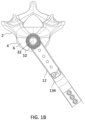
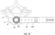
- FIGS. 1A-1C an expandable interbody fusion device or implant 10 and methods of installation are shown according to one embodiment.
- the expandable device 10 is configured to be inserted between two adjacent vertebrae 2.
- the expandable implant 10 is attached to an inserter instrument 12 to deploy the device 10 into the disc space (the upper vertebra is omitted for clarity in FIGS. 1A-1C ).
- the inserter 12 may be suitable for use during a minimally invasive surgical (MIS) procedure, for example, such that the inserter 12 and attached implant 10 may be positioned through a guide tube or cannula to access and guide the implant 10 into the disc space.
- MIS minimally invasive surgical
- the expandable implant 10 is inserted between the vertebral bodies 4 of the vertebrae 2 and into the disc space in a collapsed position.
- the implant 10 is configured to adjust the orientation of attachment of the inserter 12 relative to the implant 10 to accommodate various surgical approaches to the spine.
- the ability to adjust the implantation orientation of the implant 10 accommodates a variety of approach angles and trajectories to the spine.
- the surgical approach angles and trajectories may include direct anterior, direct lateral, oblique, and subdivided increments in-between direct anterior and direct lateral.
- FIG. 1A shows placement of implant 10 through a direct anterior approach to the spine from the front of the body. When operating on the lumbar spine, this surgical technique may also be called an anterior lumbar interbody fusion (ALIF).
- FIG. 1B shows placement of implant 10 through a non-specified oblique approach (e.g., at an angle between direct anterior and direct lateral).
- FIG. 1C shows placement of implant 10 through a direct lateral approach to the spine from a side of the body.
- this surgical technique may also be called a lateral lumbar interbody fusion (LLIF). It will be appreciated that the surgeon may determine the best surgical approach and placement of the expandable implant 10 before or during the surgery.
- LLIF lateral lumbar interbody fusion
- the implant 10 is then expanded in height to an expanded position to precisely restore normal spinal alignment and distribute the load across the vertebral endplates 6. Due to the adjustable attachment interface, the implant 10 may be oriented or angled to better contact the natural endplate curvature of the vertebral bodies 4 above and below the disc space in which the device 10 is being implanted. This may be especially beneficial in high-complexity deformity cases where vertebral bodies 4 may be rotated relative to more than one dimensional plane, thus requiring a non-typical surgical access approach to the level the surgeon desires to treat.
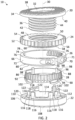
- the implant 10 includes an upper endplate 20 for engaging a superior vertebral body 4, a lower endplate 22 for engaging an inferior vertebral body 4, an expansion or actuation gear 24 for adjusting the height of the upper endplate 20, an orientation and interface collar 26 configured to attach the inserter 12 to the implant 10 at various orientations or angles for the desired surgical approach angle or trajectory, and an expansion and orientation lock 28 configured to lock the orientation of the interface collar 26 and/or automatically lock the height of the implant.
- the endplates 20, 22, actuation gear 24, interface collar 26, and lock 28 are aligned along central longitudinal axis 30.
- the implant 10 may define a large central graft retaining opening or window 32 configured to receive bone graft or other suitable bone growth enhancing material.
- the central graft window 32 may be generally cylindrical in shape with a central axis aligned with central longitudinal axis 30.
- Cylinder 36 extends from the bottom or lower surface 40 of annular body 34.
- the protruding cylinder 36 defines one or more exterior threads 42 configured to mate with corresponding threads 50 inside the actuation gear 24.
- the exterior threads 42 may include a helical thread profile machined into the outer surface of the cylinder 36.
- the exterior threads 42 may have any suitable attributes including diameters, handedness, thread form, thread angle, lead(s), pitch, etc.
- the threads 42 may extend along the entire length of cylinder 36 or a suitable portion thereof.
- a slot 44 may run the full length or partial length of the threads 42 and reaches into the central graft window 32.
- the slot 44 may be vertically oriented and in fluid communication with the central graft window 32.
- the slot 44 may be located at an angle from direct anterior to allow for access from various approach angles.
- the slot 44 may act as a backfill window and a counter-torque for expansion and collapsing of the spacer.
- the expansion gear or actuation gear 24 is configured to expand and collapse the implant 10.
- the actuation gear 24 has a central through opening 48 sized and dimensioned to receive the protruding cylinder 36 of the upper endplate 20 in a telescoping manner.
- the central opening 48 has a center axis coaxial with the central longitudinal axis 30 of the implant 10.
- the central opening 48 defines one or more inner threads 50 cut into its inner diameter configured to interface with the exterior threads 42 of the upper endplate 20. The threaded engagement between the cylinder 36 and threaded opening 48 permit the actuation gear 24 to adjust the height of upper endplate 20 when rotated.
- An outer perimeter of the actuation gear 24 includes a plurality of cogs or teeth 52.
- the actuation gear 24 may be a spur gear or straight-cut gear with straight teeth 52 projecting radially from the cylinder or disk. The edge of each tooth 52 may be straight and aligned parallel to the axis of rotation. Although a specific arrangement of teeth 52 is shown, it is envisioned that the number, location, thickness, diameters, pitch, and configuration of the teeth may be modified or selected by one skilled in the art.
- the actuation gear 24 When engaged by inserter instrument 12, the actuation gear 24 may be rotated about axis 30 to move upper endplate 20 up or down, thereby adjusting the height of the implant 10.
- the teeth 52 may extend between an upper face 54 and an opposite lower face 56 of actuation gear 24.
- the upper face 54 of the actuation gear 24 may be configured to contact the bottom surface 40 of annular body 34 of the upper endplate 20 when the upper endplate 20 is fully collapsed (as shown in FIGS. 3A-3B ).
- the lower face 56 of the actuation gear 24 is configured to contact or be adjacent to the upper surface 78 of collar 26 at all times.
- the upper and lower surfaces 54, 56 of the actuation gear 24 may be generally planar and smooth.
- the actuation gear 24 includes a snap-fit lip 58, which protrudes inferiorly and is configured to be retained by the bottom endplate 22.
- the snap-fit lip 58 may include a circular rim 60 defined by a circular groove superior to rim 60.
- the circular rim 60 protrudes radially outward to engage with the bottom endplate 22.
- a bottom portion or surface of the rim 60 may be angled or rounded to help with the snap-fit engagement.
- the lower surface 56 of the actuation gear 24 defines a plurality of pockets 62 configured to retain a portion of lock 28.
- the lock 28 is configured to interface with pockets 62 in the lower face 56 on the underside of the actuation gear 24 in order to bind the rotational movement of the expansion gear 24 and prevent both expansion and collapsing of the implant 10.
- the orientation and interface collar 26 is configured to interface with the inserter 12 for implantation. When not engaged by the inserter 12, the collar 26 is permitted to freely rotate about axis 30. When engaged by the inserter 12 in certain positions, the collar 26 is locked into position relative to the inserter 12 for implantation for a desired approach or trajectory.
- the interface collar 26 includes a split ring body 66 with a gap 68 between opposite sides of the split ring 66.
- the interface collar 26 defines one or more openings 70 through the outer face 72 of the outer diameter which are configured to interface with the inserter 12 for implantation.
- the outer face 72 may be generally smooth except for a pair of protruding oblong eyelets 71 on opposite sides of the gap 68. Each opening 70 may be defined through the respective eyelet 71.
- the inner surface 74 of the interface collar 26 includes a plurality of angled protrusions 76.
- the angled protrusions 76 may include a series of alternating protrusions and grooves configured to interface with corresponding mating surfaces 94 on the lock 28.
- the angled protrusions 76 may define flanks or ramped surfaces configured to translate the lock 28 vertically along axis 30.
- the angled protrusions 76 may extend from an upper face 78 a distance toward lower face 80 while stopping short of the lower face 80 allowing a smooth area below protrusions 76.
- a first series of angled protrusions 76 extend a distance along inner surface 74 from first opening 70 and a second series of angled protrusions 76 extend a distance along inner surface 74 from the second opening 70 with a smooth area along inner surface 74 between the two series of protrusions 76.
- a specific arrangement of angled protrusions is shown, it is envisioned that the number, location, and configuration of surfaces may be modified or selected by one skilled in the art.
- the rotatable interface collar 26 is located between the actuation gear 24 and the bottom endplate 22.
- the interface collar 26 may be retained in the bottom endplate 22 by overlapping lips 82, 120 on the collar 26 and the bottom endplate 22.
- the lip 82 on interface collar 26 may include a downward projecting lip following the body of the split ring 66 along the interior surface 74. It will be appreciated that the interface collar 26 may be retained in the bottom endplate 22 using any suitable mechanism that permits rotational movement of collar 26 about axis 30 when the collar 26 is not secured by the inserter 12.
- the collar 26 may be engaged by inserter 12 in multiple positions. In a first position, the angled protrusions 76 of the collar 26 interface with the lock 28 to prevent the collar 26 from rotating, which locks the orientation of the implant 10 relative to the inserter 12 for implantation. In a second position, the collar 26 causes the lock 28 to disengage from the actuation gear 24, thereby allowing for expansion or collapsing of the implant 10 and also prevents rotation and reorientation of the collar 26.
- the expansion and orientation lock 28 is configured to lock the orientation of the interface collar 26 and/or automatically lock the height of the implant 10.
- the outer diameter 92 of lock 28 is tapered with angled shallowed cuts 94, which interact and interface with mating protrusions 72 on the interface collar 26.
- the lock 28 includes a ring-like body 86 angled or tapered from a top edge 88 to bottom edge 90.
- the body 86 gradually increases in diameter along its circumference from top edge 88 to lower edge 90 forming an outer cone-like shape.
- the top edge 88 has a smaller diameter than bottom edge 90.
- the outer diameter of the lock 28 includes a plurality of shallow cuts 94.
- the shallow cuts 94 may be generally rectangular in shape extending vertically from upper edge 88 toward bottom edge 90.
- the cuts 94 may have equal widths and may be equally spaced about the perimeter of the lock 28 or may be otherwise configured to mate with corresponding protrusions 72 in the interface collar 26.
- the inner surface 96 of the lock 28 may
- the lock 28 has one or more guide rail posts 98 that interface with the bottom endplate 22 acting as counter-torque measure so that the lock 28 is permitted to only move in a linear fashion up and down along axis 30.
- Each guide rail post 98 may include a vertical rail protruding radially inwardly.
- four guide rails posts 98 may be spaced equally about the inner surface 94 of the lock 28. It will be appreciated that any suitable number and configuration of guide rail posts may be used to guide the movement of the lock 28.
- the tops of the guide rail posts 98 protrude upward and are configured to interface with the pockets 62 on the underside of the actuation gear 24 in order to bind the rotational movement of the actuation gear 24 and prevent expanding and collapsing of the implant 10.
- the lock 28 may include one or more spring arms 102 extending from the bottom surface 90 of the lock 28 with each terminating at a free end.
- the spring arms 102 may include a curved beam or structure that bends downward with a convex lower profile.
- a spring arm 102 may be positioned beneath each guide rail post 98. Each spring arm 102 may be machined into the lock 28 such that in the implant's unengaged state, the spring arms 102 press the lock 28 up and away from the bottom endplate 22.
- the lower endplate 22 includes an annular body 106 configured to receive the expansion and orientation lock 28, the interface collar 26, and the actuation gear 24. Similar to upper endplate 20, the annular body 106 may be a ring or circle surrounding a portion of central graft window 32. The annular body 106 has a thickness between a lower bone-engaging surface 108 and an upper edge 110 of annular body 34. As best seen in FIGS. 3A-3B and 4A-4B , the annular body 106 may be angled and/or the thickness between the upper and lower surfaces 108, 110 of the annular body 106 may vary to accommodate wide ranging anatomical profiles and to match or restore lordosis when used in the lumbar spine.
- the lower bone-engaging surface 108 of lower endplate 22 is configured to engage an inferior vertebral body 4.
- the lower bone-engaging surface 108 may be contoured to mimic the shape of the vertebral endplate 6. Similar to upper bone-engaging surface 38, lower bone-engaging surface 108 may include a plurality of teeth, protrusions, or other friction enhancing surfaces configured to engage bone.
- the bottom endplate 22 includes aggregate-like expulsion resistant patterns or textures on the inferior surface geometry for contacting bony surfaces that can be angled to match or restore lordosis when used in the lumbar spine.
- the lower bone-engaging surface 108 may further include a porosity or porous structure to allow for additional ingrowth of bone into the spacer.
- the lower endplate 22 may be 3D printed, for example, to enhance boney on-growth potential. It will be appreciated that the bone-engaging surface 108 may be modified to include one or more surface treatments, coatings, textures, expulsion resistant structures or geometries, or other features to enhance fusion.
- the expansion and orientation lock 28 lives nested inside of pockets and grooves 112 machined into the bottom endplate 22.
- the lower endplate 22 has an inner wall 114 define by a portion of central graft window 32.
- a plurality of snap-fit posts 116 extend vertically from the inner wall 114.
- the snap-fit posts 116 are arranged in pairs with a space 118 therebetween configured to receive respective guide rail posts 98 of the lock 28.
- four pairs of snap-fit posts 116 are spaced equally around the inner wall 114 defining four respective spaces 118 for corresponding guide rail posts 98.
- the guide rail posts 98 interface with the spaces 118 between the snap-fit posts 116 to guide movement of the lock 28 in a linear fashion up and down along axis 30. Although a certain number and configuration of posts 98, 116 are shown, it will be appreciated that another suitable arrangement may be selected to guide lock 28.
- the interface collar 26 is placed into lower endplate 22 such that the collar 26 surrounds and engages lock 28.
- the interface collar 26 may be retained in the lower endplate 22 by overlapping lips 82, 120 on the collar 26 and bottom endplate 22.
- the collar 26 may be sized and dimensioned such that the outer face 72 of the orientation collar 26 is generally flush with the outer circumference of the annular body 106 of the lower endplate 22.
- the actuation gear 24 may then be positioned on top of the orientation collar 26 and secured to the lower endplate 22.
- the lower face 56 of the actuation gear 24 abuts the upper face 78 of the interface collar 26.
- the actuation gear 24 may be sized and dimensioned such that the outer diameter of the gear 24 is generally flush with the outer face 72 of the interface collar 26 and the outer circumference of the annular body 34 of the upper endplate 20.
- the lower face 56 of actuation gear 24 rests on top of the snap-fit posts 116 in the bottom endplate 22.
- the actuation gear 24 is retained in the bottom endplate 22 via snap-fit lip 60.
- Each of the free ends of snap-fit posts 116 define an overhang or finger 122 configured to fit in the groove defining circular rim 60 of actuation gear 24.
- the snap-fit posts 116 may be configured to flex or bend slightly as the fingers 122 are inserted, thereby securely connecting the actuation gear 24 to the lower endplate 22.
- the upper endplate 20 is threadedly engaged with actuation gear 24.
- a pillar 124 may protrude vertically from lower endplate 22, which is sized and configured to fit within slot 44 in the cylinder 36 of the upper endplate 20.
- the slot 44 and pillar 124 may act as a counter-torque measure for expansion and collapsing of the spacer.
- the bottom surface 40 of the annular body 34 of the upper endplate 20 may contact and abut the upper face 54 of the actuation gear 24.
- the annular body 34 of the upper endplate 20 lifts off the actuation gear 24 and the bottom surface 40 of the annular body 34 is spaced apart from the actuation gear 24.
- the devices described herein or components thereof may be manufactured from a number of biocompatible materials including, but not limited to, titanium, titanium alloys, non-titanium metallic alloys, stainless steel, polymeric materials, plastics, plastic composites, polyetheretherketone (PEEK), ceramics, and elastic materials.
- the devices or components thereof may be manufactured by machining, additive processes such as 3-dimensional (3D) printing, and/or subtractive processes.
- implant 10 is insertable into the disc space with inserter 12 through an agnostic approach.
- the surgeon is able to determine the trajectory or approach to the spine before or during the procedure and is able to adjust the orientation of the implant 10 during the procedure to accommodate the desired surgical approach.
- the implant 10 is configured to be inserted from multiple approaches without the need for an extensive set of implants with fixed approach-specific insertion features.
- the ability of implant 10 to be inserted from multiple approaches and trajectories can significantly reduce the number of necessary implants in the set list for a given procedure.
- the flexibility of implant 10 also provides the surgeon with more choices and greater control during the procedure, thereby resulting in better patient outcomes.
- FIGS. 6A-6C show inserter instrument 12 attached to implant 10 according to one embodiment.
- the inserter 12 controls the position of the interface collar 26, the position of the lock 28, and the expanded height of the top endplate 20 when properly attached.
- the inserter 12 extends from a proximal end 130 to a distal end 132 along a central longitudinal tool axis.
- the proximal end 130 includes an attachment interface for connecting a handle (not shown) configured to be manipulated by a user.
- the distal end 132 is configured to attach to the interface collar 26 of the implant 10.
- the inserter 12 includes a main outer body 134 in the form of a hollow outer tube or cannula defining a central channel configured to receive an expansion assembly including an expansion drive shaft 136 configured to expand the implant 10 and an attachment assembly including a distal attachment fork 140 configured to engage the interface collar 26 in different positions.
- the expansion assembly may include expansion drive shaft 136, which is a cylindrical shaft extending through outer body 134, attached to a drive gear 138 configured to engage with the actuation gear 24 of the implant 10.
- the proximal end 130 of expansion drive shaft 136 is connectable to a handle (not shown) to allow for rotation of the drive shaft 136.
- the attachment assembly may include attachment fork 140, which includes a central body or base 142 with a pair of distal prongs 144 extending therefrom.
- the prongs 144 may be straight or curved and may be spaced apart to match the spacing of the attachment locations 70 along the interface collar 26.
- the prongs 144 may be configured to flex or bend slightly to engage the interface collar 26 in different positions.
- the free end 146 of each prong 144 may be inserted into respective opening 70 and may be contoured or shaped to engage with opposite sides of the opening 70.
- a sleeve 148 may be configured to draw the prongs 144 together or apart.
- An outer control knob 150 and inner half nut 152 may be used to manipulate the prongs 144.
- control knob 150 may be rotated to translate sleeve 148 to draw prongs 144 together or allow prongs 144 to spread apart from one another. It will be appreciated that any suitable mechanism may be used to control movement of the attachment fork 140 and prongs 144.
- FIG. 7 shows the inserter 12 attached to implant 10 such that the attachment fork 140 is not engaged with the interface collar 26, thereby providing a neutral or open position.
- the collar 26 is permitted to freely rotate 360° around the central axis 30 of the implant core.
- the angled protrusions 76 of the interface collar 26 are not received in the shallow cuts 94 of the lock 28.
- the open position occurs when the control knob 150 is twisted such that the attachment fork 138 results in a position where the prongs 144 of the fork 140 are not engaged with the attachment points 70 on the interface collar 26.
- FIG. 7 shows the prong 144 in a neutral position in opening 70 of the interface collar 26, thereby allowing for full rotation of the interface collar 26 to the desired insertion orientation.
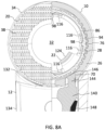
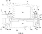
- FIGS. 8A-8B show the inserter 12 attached to implant 10 at the half position.
- the attachment fork 140 is engaged with the interface collar 26
- the prong 144 is located in opening 70 of the interface collar 26 such that the prongs 144 move away from one another.
- the protrusions 76 of interface collar 26 bind with the cuts 94 on the lock 28 and prevent the collar 26 from rotating, which in turn defines the orientation of the implant 10 relative to the inserter 12 for implantation.
- the half position occurs when the control knob 150 is twisted such that the attachment fork 140 results in a position where the prongs 144 of the fork 140 are forcing the ramped interacting features on the interface collar 26 to engage with the lock 28.
- the orientation of the interface collar 26 is rigidly defined, while not unlocking the expansion mechanism.
- FIGS. 9A-9B show the inserter 12 attached to implant 10 at the full position.
- the ramped features of the interface collar 26 push into and down on the lock 28 disengaging the rail posts 98 from the underside of the gear 24 allowing for expansion or collapsing of the implant 10, as well as implantation or removal.
- the full position also prevents rotation and reorientation of the collar 26.
- the prongs 144 of the attachment fork 144 may be drawn toward one another to grip the interface collar 26 such that the ends of split ring 66 approach one another, thereby causing the interface collar 26 to engage the lock 28.
- the full position occurs when the control knob 150 is twisted such that the attachment fork 140 results in a position where the prongs 144 of the fork 140 are forcing the interacting features 76 on the interface collar 26 to engage with the lock 28.
- the orientation of the interface collar 26 is rigidly defined and the ramped interacting features 76 of the interface collar 26 push the lock 28 downward and away from the expansion gear 24.
- the upper ends of guide rail posts 98 on the lock 28 disengage from the pockets 62 in lower surface 56 of the actuation gear 24, thereby unlocking the implant 10.
- the upper endplate 20 may be raised or lowered.
- the expansion drive shaft 136 of the inserter 12 causes expansion or contraction of the spacer 10.
- the drive gear 138 engages the actuation gear 24, thereby permitting adjustment of the height of the implant 10.
- turning the expansion drive shaft 136 on the inserter 12 will not cause the spacer 10 to expand or contract as the lock 28 will be binding with the expansion gear 24, thereby preventing this movement.
- the lock 28 automatically reengages with the actuation gear 24 such that the springs 102 push the lock 28 upwards and the upper ends of guide rail posts 98 re-enter the pockets 62 in lower surface 56 of the actuation gear 24, thereby re-locking the implant 10 and preventing any further expansion or contraction of the implant 10.
- robotic and/or navigation guidance may be used to assist in orienting and installing the implant 10 along one or more of the agnostic approaches. Details of surgical robotic and/or navigation systems can be found, for example, in U.S. Patent No. 10,675,094 and U.S. Patent No. 9,782,229 , which are incorporated by reference herein in their entireties for all purposes.
- the implant 10 may be implanted with one or more of the following steps: (1) determining optimal implant location and positioning to optimize contacted bone and desired correction; (2) employing robotic and/or navigational systems to determine the potential trajectories to allow for optimal implant location and outcome; (3) optionally docking a cannula on the disc space through a suitable trajectory including direct anterior, direct lateral, or a non-specified oblique approach between anterior and lateral; (4) inserting the expandable interbody 10 into the disc space in a collapsed position through the given trajectory; and (5) expanding the expandable interbody 10 in height to precisely restore disc height and spinal alignment (e.g., lordosis).
- the implant and systems described herein may include one or more of the following advantages: (1) the ability to adjust the orientation of attachment to the implant to accommodate various approaches; (2) an internal automatic lock that both provides discrete orientation positions about the central axis of the implant and automatically locks the device after insertion into the disc space; and (3) the ability to expand in height when implanted to achieve a desired spacer height which in turn provides a desired disc height.
- the ability to adjust the implantation orientation of the spacer relative to the spacer's sagittal angle accommodates a variety of approach angles and trajectories which include, but are not limited to, direct anterior, direct lateral, oblique, and subdivided increments in-between direct anterior and direct lateral.
- the spacer has a retained interfacing collar which can freely rotate about the device's central axis. By pivoting/rotating about the central axis, the device can be oriented to better interface with the natural endplate curvature of the vertebral bodies above and below the disc space in which the device is being implanted. This may be especially beneficial in high-complexity deformity cases where vertebral bodies may be rotated relative to more than one dimensional plane, thus requiring a non-typical surgical access approach to the level the surgeon desires to treat.
- the automatic lock with discrete orientation positions provides two functions of both automatically locking the implant preventing expansion and collapsing of the implant, and discretely orienting the implant on the inserter for implantation.
- the automatic lock function reduces the steps intraoperatively needed to successfully implant the device potentially reducing cognitive load on the surgeon.
- the discrete orientations the lock provides allow the surgeon to adapt to the approach that best fits the patient's anatomy.
- the expandable implant is inserted into the intervertebral disc space at a collapsed height and then expand axially to restore height loss in the disc space.
- the ability to expand in height when implanted allows for the surgeon to restore collapsed disc height at any height from the implant starting height up to and including the fully expanded height.
- the expandable interbody spacer maximizes volume within and around the device for graft material.
Landscapes
- Health & Medical Sciences (AREA)
- Engineering & Computer Science (AREA)
- Biomedical Technology (AREA)
- Orthopedic Medicine & Surgery (AREA)
- Neurology (AREA)
- Transplantation (AREA)
- Heart & Thoracic Surgery (AREA)
- Oral & Maxillofacial Surgery (AREA)
- Cardiology (AREA)
- Vascular Medicine (AREA)
- Life Sciences & Earth Sciences (AREA)
- Animal Behavior & Ethology (AREA)
- General Health & Medical Sciences (AREA)
- Public Health (AREA)
- Veterinary Medicine (AREA)
- Physical Education & Sports Medicine (AREA)
- Prostheses (AREA)
Abstract
Description
- The present disclosure relates to surgical devices, and more particularly, to expandable fusion devices capable of being deployed inside an intervertebral disc space and then expanded in height to maintain disc spacing, restore spinal stability, and/or facilitate an intervertebral fusion.
- A common procedure for handling pain associated with intervertebral discs that become degenerated due to various factors such as trauma or aging is the use of intervertebral fusion devices for fusing one or more adjacent vertebral bodies. Generally, to fuse the adjacent vertebral bodies, the intervertebral disc is first partially or fully removed. An intervertebral fusion device is then typically inserted between neighboring vertebrae to maintain normal disc spacing and restore spinal stability, thereby facilitating an intervertebral fusion.
- There are a number of fusion devices and methodologies for accomplishing the intervertebral fusion. These may include solid bone implants, fusion devices which include a cage or other implant mechanism, which may be packed with bone and/or bone growth inducing substances, and expandable implants. The implants may be installed between adjacent vertebral bodies in order to fuse the vertebral bodies together, thereby alleviating the associated pain and providing disc height restoration.
- Interbody devices have been used to provide support and stability in the anterior column of the spinal vertebrae when treating a variety of spinal conditions, including degenerative disc disease and spinal stenosis with spondylolisthesis. Clinical treatment of spinal pathologies with anterior vertebral body interbody devices relies on precise placement of the interbody device to restore normal anterior column alignment. Iatrogenic pathologies may result from the surgical access window to the disc space, failure to precisely place the interbody on hard cortical bone often found on the apophyseal ring of the vertebral body, and/or failure to precisely control and restore normal anatomical spinal alignment.
- As such, there exists a need for a fusion device capable of being inserted into the intervertebral disc space at a collapsed height and then expand axially to restore height loss in the disc space and further provides precise placement of the interbody, which may be inserted from multiple approaches to allow access to the spine without the need for an extensive set of implants with fixed approach-specific insertion features.
- To meet this and other needs, and in view of its purposes, the present application provides devices, systems, instruments, and methods for installing and expanding an implant. In particular, an expandable fusion device is provided, which can be inserted from any approach which allows access to the spine. The expandable fusion device may have the ability to adjust the orientation of attachment to the implant to accommodate various approaches, an internal automatic lock that both provides discrete orientation positions about the central axis of the implant and automatically locks the device after insertion into the disc space, and/or has the ability to expand in height when implanted to achieve a desired spacer height which in turn provides a desired disc height.
- According to one embodiment, an expandable implant includes an upper endplate and a lower endplate configured to engage adjacent vertebrae, an actuation gear configured to adjust a height of the upper endplate, the actuation gear is coupled to the lower endplate and engaged with the upper endplate, an interface collar configured to attach to an inserter instrument at multiple orientations for a desired surgical approach, the interface collar includes a plurality of angled protrusions, and an expansion and orientation lock configured to lock the orientation of the interface collar and lock the height of the upper endplate, the lock is retained in the lower endplate, the lock includes a tapered outer surface with a plurality of cuts defined therein configured to interface with the plurality of angled protrusions in the interface collar.
- The expandable implant may include one or more of the following features. The interface collar may be free to rotate about a center axis of the implant when not engaged by the inserter instrument or engaged in the open position. The interface collar may be a split ring with a gap between opposite sides of the split ring. The interface collar may include a pair of eyelets defining a pair of openings through the interface collar. The lower endplate may include a plurality of snap-fit posts arranged in pairs defining a space therebetween, and the lock may include a plurality of guide rail posts configured to fit into the spaces between the snap-fit posts, thereby guiding movement of the lock. The tops of the guide rail posts may protrude upward from the lock and are configured to interface with pockets on an underside of the actuation gear in order to bind rotational movement of the actuation gear and prevent expanding and collapsing of the implant. The lock may include a plurality of spring arms extending from a bottom surface of the lock, wherein in an unengaged state, the spring arms press the lock up and away from the bottom endplate. The actuation gear may include a disk with a plurality of teeth projecting radially outward therefrom and a threaded central opening configured to threadedly mate with the upper endplate. The upper endplate may include an annular body with a bone-engaging surface and an inferiorly protruding cylinder configured to mate with the actuation gear. The inferiorly protruding cylinder of the upper endplate may include exterior threads and a vertical slot bisecting the exterior threads, and the lower endplate may include a pillar receivable in the vertical slot.
- According to one embodiment, an implantable system includes an expandable implant and an inserter instrument. The expandable implant includes an upper endplate configured to engage a superior vertebra, an actuation gear configured to adjust a height of the upper endplate, an interface collar configured to rotate about a center axis of the implant for a desired surgical approach, an expansion and orientation lock configured to lock the orientation of the interface collar and lock the height of the upper endplate, and a lower endplate configured to engage an inferior vertebra. The inserter instrument has an attachment assembly configured to engage the interface collar and an expansion assembly configured to expand the implant. The inserter instrument is attachable to the interface collar in an open position, a half position, and a full position to control a location of the interface collar and expansion of the implant.
- The implantable system may include one or more of the following features. The attachment assembly may include an attachment fork with a pair of prongs. The interface collar may include a pair of openings configured to receive the prongs of the attachment fork. In the open position, the inserter instrument is attached to the implant such that the attachment fork is not engaged with the interface collar, thereby allowing full rotation of the interface collar and the lock prevents expansion of the upper endplate. In the half position, the inserter instrument is attached to the implant such that the attachment fork is engaged with the interface collar, thereby securing the location of the interface collar and the lock prevents expansion of the upper endplate. In the full position, the inserter instrument is attached to the implant such that the attachment fork is engaged with the interface collar, thereby securing the location of the interface collar and the lock disengages from the actuation gear allowing for expansion of the upper endplate.
- According to another embodiment, a method of installing an expandable implant includes: (a) providing an expandable implant comprising an upper endplate configured to engage a superior vertebra, an actuation gear configured to adjust a height of the upper endplate, an interface collar configured to rotate about a center axis of the implant for a desired surgical approach, an expansion and orientation lock configured to lock the orientation of the interface collar and lock the height of the upper endplate, and a lower endplate configured to engage an inferior vertebra; and (b) attaching an inserter instrument to the interface collar, wherein the inserter instrument is configured to move the interface collar to an open position allowing for full rotation of the interface collar and the lock prevents expansion of the upper endplate, a half position locking a location of the interface collar and the lock prevents expansion of the upper endplate, or a full position locking a location of the interface collar and the lock disengages from the actuation gear allowing for expansion of the upper endplate. The inserter instrument may be attached to the interface collar to establish a desired trajectory including direct anterior, direct lateral, or a non-specified oblique approach between direct anterior and direct lateral. When the inserter instrument moves the interface collar to the half or full position, locking the location of the interface collar, the expandable implant may be positioned into a disc space in a collapsed position. When the inserter instrument moves the interface collar to the full position, the lock disengages from the actuation, and the actuation gear may be rotated to adjust the height of the upper endplate.
- Also provided are kits including expandable fusion devices of varying types and sizes, rods, fasteners or anchors, k-wires, insertion tools, and other components for performing the procedure.
- A more complete understanding of the present invention, and the attendant advantages and features thereof, will be more readily understood by reference to the following detailed description when considered in conjunction with the accompanying drawings, wherein:
-
FIGS. 1A-1C show an inserter instrument attached to an expandable implant for a direct anterior approach, non-specified oblique approach, and direct lateral approach, respectively, according to one embodiment; -
FIG. 2 is an exploded view of the expandable implant according to one embodiment; -
FIGS. 3A-3B show front and left side views, respectively, of the expandable fusion device ofFIG. 2 at the collapsed starting height; -
FIGS. 4A-4B show front and left views, respectively, of the expandable fusion device ofFIG. 2 fully expanded in height; -
FIG. 5 shows a top view of the expandable fusion device ofFIG. 2 ; -
FIGS. 6A-6C show top and cross-sectional views, respectively, of the inserter instrument attached to the expandable implant according to one embodiment; -
FIG. 7 shows a partial top view (left side) and a partial cross-sectional view (right side) of the inserter instrument in a neutral open position with the implant but not engaged with the interface collar; -
FIGS. 8A-8B show a partial top view (left side) and a partial cross-sectional view (right side) and a side cross-sectional view, respectively, of the inserter instrument located at a half locking position with the implant to lock the implantation trajectory but not unlocking the expansion gear; and -
FIGS. 9A-9B show a partial top view (left side) and a partial cross-sectional view (right side) and a side cross-sectional view, respectively, of the inserter instrument located at a full locking position with the implant to lock the implantation trajectory and unlocking the expansion gear to allow for expansion or contraction of the implant. - In order to restore height loss in the disc space and provide precise placement of the interbody, the expandable implant may have the ability to: (1) adjust the orientation of attachment to the implant to accommodate various surgical approaches; (2) an internal automatic lock that both provides discrete orientation positions about the central axis of the implant and automatically locks the device after insertion into the disc space; and (3) the ability to expand in height when implanted to achieve a desired spacer height which in turn provides a desired disc height. Accordingly, embodiments of the present application are generally directed to devices, systems, instruments, and methods for installing and expanding the interbody implant. The terms implant, interbody, interbody implant, fusion device, spacer, and expandable device may be used interchangeably herein. Although described with reference to an interbody implant, it will be appreciated that the implant may also be used as a corpectomy spacer and placed between non-adjacent vertebral bodies or may be used in trauma or other suitable surgical applications.
- Referring now to
FIGS. 1A-1C , an expandable interbody fusion device orimplant 10 and methods of installation are shown according to one embodiment. Theexpandable device 10 is configured to be inserted between twoadjacent vertebrae 2. Theexpandable implant 10 is attached to aninserter instrument 12 to deploy thedevice 10 into the disc space (the upper vertebra is omitted for clarity inFIGS. 1A-1C ). Theinserter 12 may be suitable for use during a minimally invasive surgical (MIS) procedure, for example, such that theinserter 12 and attachedimplant 10 may be positioned through a guide tube or cannula to access and guide theimplant 10 into the disc space. Theexpandable implant 10 is inserted between thevertebral bodies 4 of thevertebrae 2 and into the disc space in a collapsed position. - The
implant 10 is configured to adjust the orientation of attachment of theinserter 12 relative to theimplant 10 to accommodate various surgical approaches to the spine. The ability to adjust the implantation orientation of theimplant 10 accommodates a variety of approach angles and trajectories to the spine. The surgical approach angles and trajectories may include direct anterior, direct lateral, oblique, and subdivided increments in-between direct anterior and direct lateral.FIG. 1A shows placement ofimplant 10 through a direct anterior approach to the spine from the front of the body. When operating on the lumbar spine, this surgical technique may also be called an anterior lumbar interbody fusion (ALIF).FIG. 1B shows placement ofimplant 10 through a non-specified oblique approach (e.g., at an angle between direct anterior and direct lateral).FIG. 1C shows placement ofimplant 10 through a direct lateral approach to the spine from a side of the body. When operating on the lumbar spine, this surgical technique may also be called a lateral lumbar interbody fusion (LLIF). It will be appreciated that the surgeon may determine the best surgical approach and placement of theexpandable implant 10 before or during the surgery. - Once inserted into the disc space through the desired surgical approach, the
implant 10 is then expanded in height to an expanded position to precisely restore normal spinal alignment and distribute the load across thevertebral endplates 6. Due to the adjustable attachment interface, theimplant 10 may be oriented or angled to better contact the natural endplate curvature of thevertebral bodies 4 above and below the disc space in which thedevice 10 is being implanted. This may be especially beneficial in high-complexity deformity cases wherevertebral bodies 4 may be rotated relative to more than one dimensional plane, thus requiring a non-typical surgical access approach to the level the surgeon desires to treat. - Turning now to
FIG. 2 , an exploded view ofexpandable implant 10 is shown according to one embodiment. Theimplant 10 includes anupper endplate 20 for engaging a superiorvertebral body 4, alower endplate 22 for engaging an inferiorvertebral body 4, an expansion oractuation gear 24 for adjusting the height of theupper endplate 20, an orientation andinterface collar 26 configured to attach theinserter 12 to theimplant 10 at various orientations or angles for the desired surgical approach angle or trajectory, and an expansion and orientation lock 28 configured to lock the orientation of theinterface collar 26 and/or automatically lock the height of the implant. Theendplates actuation gear 24,interface collar 26, and lock 28 are aligned along centrallongitudinal axis 30. Theimplant 10 may define a large central graft retaining opening orwindow 32 configured to receive bone graft or other suitable bone growth enhancing material. As best seen inFIG. 5 , thecentral graft window 32 may be generally cylindrical in shape with a central axis aligned with centrallongitudinal axis 30. - The top or
upper endplate 20 includes anannular body 34 with an inferiorly protrudingcylinder 36 configured to mate with theactuation gear 24. Theannular body 34 may be a ring or circle surrounding a portion of thecentral graft window 32. Theannular body 34 has a thickness between an upper bone-engagingsurface 38 and a bottom orlower surface 40 ofannular body 34. As best seen inFIGS. 3A-3B and4A-4B , theannular body 34 may be angled and/or the thickness between the upper andlower surfaces annular body 34 may vary to accommodate wide ranging anatomical profiles and to match or restore lordosis when used in the lumbar spine. - The
annular body 34 includes upper bone-engagingsurface 38 configured to engage a superiorvertebral body 4. The upper bone-engagingsurface 38 may be contoured to mimic the shape of thevertebral endplate 6. The upper bone-engagingsurface 38 may include a plurality of teeth, protrusions, or other friction enhancing surfaces configured to engage bone. In one embodiment, theupper endplate 20 includes aggregate-like expulsion resistant patterns or textures on the superior surface geometry for contacting bony surfaces that can be angled to match or restore lordosis when used in the lumbar spine. The bony-contactingsurface 38 may further include a porosity or porous structure to allow for additional ingrowth of bone into the spacer. Theupper endplate 20 may be 3D printed, for example, to enhance boney on-growth potential. It will be appreciated that the bone-engagingsurface 38 may be modified to include one or more surface treatments, coatings, textures, or other features to enhance fusion. -
Cylinder 36 extends from the bottom orlower surface 40 ofannular body 34. The protrudingcylinder 36 defines one or moreexterior threads 42 configured to mate withcorresponding threads 50 inside theactuation gear 24. Theexterior threads 42 may include a helical thread profile machined into the outer surface of thecylinder 36. Theexterior threads 42 may have any suitable attributes including diameters, handedness, thread form, thread angle, lead(s), pitch, etc. Thethreads 42 may extend along the entire length ofcylinder 36 or a suitable portion thereof. As thecylinder 36 is telescopingly received in/from theactuation gear 24, theupper endplate 20 is configured to raise or lower in height, thereby adjusting the overall height of theimplant 10. Aslot 44 may run the full length or partial length of thethreads 42 and reaches into thecentral graft window 32. Theslot 44 may be vertically oriented and in fluid communication with thecentral graft window 32. Theslot 44 may be located at an angle from direct anterior to allow for access from various approach angles. Theslot 44 may act as a backfill window and a counter-torque for expansion and collapsing of the spacer. - The expansion gear or
actuation gear 24 is configured to expand and collapse theimplant 10. Theactuation gear 24 has a central through opening 48 sized and dimensioned to receive the protrudingcylinder 36 of theupper endplate 20 in a telescoping manner. Thecentral opening 48 has a center axis coaxial with the centrallongitudinal axis 30 of theimplant 10. Thecentral opening 48 defines one or moreinner threads 50 cut into its inner diameter configured to interface with theexterior threads 42 of theupper endplate 20. The threaded engagement between thecylinder 36 and threadedopening 48 permit theactuation gear 24 to adjust the height ofupper endplate 20 when rotated. - An outer perimeter of the
actuation gear 24 includes a plurality of cogs orteeth 52. In one embodiment, theactuation gear 24 may be a spur gear or straight-cut gear withstraight teeth 52 projecting radially from the cylinder or disk. The edge of eachtooth 52 may be straight and aligned parallel to the axis of rotation. Although a specific arrangement ofteeth 52 is shown, it is envisioned that the number, location, thickness, diameters, pitch, and configuration of the teeth may be modified or selected by one skilled in the art. When engaged byinserter instrument 12, theactuation gear 24 may be rotated aboutaxis 30 to moveupper endplate 20 up or down, thereby adjusting the height of theimplant 10. - The
teeth 52 may extend between anupper face 54 and an oppositelower face 56 ofactuation gear 24. Theupper face 54 of theactuation gear 24 may be configured to contact thebottom surface 40 ofannular body 34 of theupper endplate 20 when theupper endplate 20 is fully collapsed (as shown inFIGS. 3A-3B ). Thelower face 56 of theactuation gear 24 is configured to contact or be adjacent to theupper surface 78 ofcollar 26 at all times. The upper andlower surfaces actuation gear 24 may be generally planar and smooth. - The
actuation gear 24 includes a snap-fit lip 58, which protrudes inferiorly and is configured to be retained by thebottom endplate 22. As best seen inFIG. 8B , the snap-fit lip 58 may include acircular rim 60 defined by a circular groove superior torim 60. Thecircular rim 60 protrudes radially outward to engage with thebottom endplate 22. A bottom portion or surface of therim 60 may be angled or rounded to help with the snap-fit engagement. Thelower surface 56 of theactuation gear 24 defines a plurality ofpockets 62 configured to retain a portion oflock 28. Thelock 28 is configured to interface withpockets 62 in thelower face 56 on the underside of theactuation gear 24 in order to bind the rotational movement of theexpansion gear 24 and prevent both expansion and collapsing of theimplant 10. - The orientation and
interface collar 26 is configured to interface with theinserter 12 for implantation. When not engaged by theinserter 12, thecollar 26 is permitted to freely rotate aboutaxis 30. When engaged by theinserter 12 in certain positions, thecollar 26 is locked into position relative to theinserter 12 for implantation for a desired approach or trajectory. Theinterface collar 26 includes asplit ring body 66 with agap 68 between opposite sides of thesplit ring 66. Theinterface collar 26 defines one ormore openings 70 through theouter face 72 of the outer diameter which are configured to interface with theinserter 12 for implantation. Theouter face 72 may be generally smooth except for a pair of protrudingoblong eyelets 71 on opposite sides of thegap 68. Eachopening 70 may be defined through therespective eyelet 71. - The
inner surface 74 of theinterface collar 26 includes a plurality ofangled protrusions 76. The angledprotrusions 76 may include a series of alternating protrusions and grooves configured to interface with corresponding mating surfaces 94 on thelock 28. The angledprotrusions 76 may define flanks or ramped surfaces configured to translate thelock 28 vertically alongaxis 30. The angledprotrusions 76 may extend from an upper face 78 a distance towardlower face 80 while stopping short of thelower face 80 allowing a smooth area belowprotrusions 76. In one embodiment, a first series of angledprotrusions 76 extend a distance alonginner surface 74 fromfirst opening 70 and a second series of angledprotrusions 76 extend a distance alonginner surface 74 from thesecond opening 70 with a smooth area alonginner surface 74 between the two series ofprotrusions 76. Although a specific arrangement of angled protrusions is shown, it is envisioned that the number, location, and configuration of surfaces may be modified or selected by one skilled in the art. - The
rotatable interface collar 26 is located between theactuation gear 24 and thebottom endplate 22. Theinterface collar 26 may be retained in thebottom endplate 22 by overlappinglips collar 26 and thebottom endplate 22. Thelip 82 oninterface collar 26 may include a downward projecting lip following the body of thesplit ring 66 along theinterior surface 74. It will be appreciated that theinterface collar 26 may be retained in thebottom endplate 22 using any suitable mechanism that permits rotational movement ofcollar 26 aboutaxis 30 when thecollar 26 is not secured by theinserter 12. - The
interface collar 26, when not engaged by theinserter 12, is permitted to freely rotate 360° around thecentral axis 30 of the implant core. Thecollar 26 may be engaged byinserter 12 in multiple positions. In a first position, the angledprotrusions 76 of thecollar 26 interface with thelock 28 to prevent thecollar 26 from rotating, which locks the orientation of theimplant 10 relative to theinserter 12 for implantation. In a second position, thecollar 26 causes thelock 28 to disengage from theactuation gear 24, thereby allowing for expansion or collapsing of theimplant 10 and also prevents rotation and reorientation of thecollar 26. - The expansion and orientation lock 28 is configured to lock the orientation of the
interface collar 26 and/or automatically lock the height of theimplant 10. Theouter diameter 92 oflock 28 is tapered with angled shallowedcuts 94, which interact and interface withmating protrusions 72 on theinterface collar 26. Thelock 28 includes a ring-like body 86 angled or tapered from atop edge 88 tobottom edge 90. Thebody 86 gradually increases in diameter along its circumference fromtop edge 88 tolower edge 90 forming an outer cone-like shape. Thus, thetop edge 88 has a smaller diameter thanbottom edge 90. The outer diameter of thelock 28 includes a plurality ofshallow cuts 94. Theshallow cuts 94 may be generally rectangular in shape extending vertically fromupper edge 88 towardbottom edge 90. Thecuts 94 may have equal widths and may be equally spaced about the perimeter of thelock 28 or may be otherwise configured to mate with correspondingprotrusions 72 in theinterface collar 26. Theinner surface 96 of thelock 28 may be smooth. - The
lock 28 has one or more guide rail posts 98 that interface with thebottom endplate 22 acting as counter-torque measure so that thelock 28 is permitted to only move in a linear fashion up and down alongaxis 30. Eachguide rail post 98 may include a vertical rail protruding radially inwardly. For example, four guide rails posts 98 may be spaced equally about theinner surface 94 of thelock 28. It will be appreciated that any suitable number and configuration of guide rail posts may be used to guide the movement of thelock 28. The tops of the guide rail posts 98 protrude upward and are configured to interface with thepockets 62 on the underside of theactuation gear 24 in order to bind the rotational movement of theactuation gear 24 and prevent expanding and collapsing of theimplant 10. Thelock 28 may include one ormore spring arms 102 extending from thebottom surface 90 of thelock 28 with each terminating at a free end. Thespring arms 102 may include a curved beam or structure that bends downward with a convex lower profile. Aspring arm 102 may be positioned beneath eachguide rail post 98. Eachspring arm 102 may be machined into thelock 28 such that in the implant's unengaged state, thespring arms 102 press thelock 28 up and away from thebottom endplate 22. - The
lower endplate 22 includes anannular body 106 configured to receive the expansion andorientation lock 28, theinterface collar 26, and theactuation gear 24. Similar toupper endplate 20, theannular body 106 may be a ring or circle surrounding a portion ofcentral graft window 32. Theannular body 106 has a thickness between a lower bone-engagingsurface 108 and anupper edge 110 ofannular body 34. As best seen inFIGS. 3A-3B and4A-4B , theannular body 106 may be angled and/or the thickness between the upper andlower surfaces annular body 106 may vary to accommodate wide ranging anatomical profiles and to match or restore lordosis when used in the lumbar spine. - The lower bone-engaging
surface 108 oflower endplate 22 is configured to engage an inferiorvertebral body 4. The lower bone-engagingsurface 108 may be contoured to mimic the shape of thevertebral endplate 6. Similar to upper bone-engagingsurface 38, lower bone-engagingsurface 108 may include a plurality of teeth, protrusions, or other friction enhancing surfaces configured to engage bone. In one embodiment, thebottom endplate 22 includes aggregate-like expulsion resistant patterns or textures on the inferior surface geometry for contacting bony surfaces that can be angled to match or restore lordosis when used in the lumbar spine. The lower bone-engagingsurface 108 may further include a porosity or porous structure to allow for additional ingrowth of bone into the spacer. Thelower endplate 22 may be 3D printed, for example, to enhance boney on-growth potential. It will be appreciated that the bone-engagingsurface 108 may be modified to include one or more surface treatments, coatings, textures, expulsion resistant structures or geometries, or other features to enhance fusion. - Assembly, counter-torque, and interfacing features for the
lock 28 are machined into an upper portion of thelower endplate 22. The expansion and orientation lock 28 lives nested inside of pockets andgrooves 112 machined into thebottom endplate 22. Thelower endplate 22 has aninner wall 114 define by a portion ofcentral graft window 32. A plurality of snap-fit posts 116 extend vertically from theinner wall 114. The snap-fit posts 116 are arranged in pairs with aspace 118 therebetween configured to receive respective guide rail posts 98 of thelock 28. In the embodiment shown, four pairs of snap-fit posts 116 are spaced equally around theinner wall 114 defining fourrespective spaces 118 for corresponding guide rail posts 98. The guide rail posts 98 interface with thespaces 118 between the snap-fit posts 116 to guide movement of thelock 28 in a linear fashion up and down alongaxis 30. Although a certain number and configuration ofposts lock 28. - After the
lock 28 is positioned intolower endplate 22, theinterface collar 26 is placed intolower endplate 22 such that thecollar 26 surrounds and engageslock 28. Theinterface collar 26 may be retained in thelower endplate 22 by overlappinglips collar 26 andbottom endplate 22. Thecollar 26 may be sized and dimensioned such that theouter face 72 of theorientation collar 26 is generally flush with the outer circumference of theannular body 106 of thelower endplate 22. - The
actuation gear 24 may then be positioned on top of theorientation collar 26 and secured to thelower endplate 22. Thelower face 56 of theactuation gear 24 abuts theupper face 78 of theinterface collar 26. Theactuation gear 24 may be sized and dimensioned such that the outer diameter of thegear 24 is generally flush with theouter face 72 of theinterface collar 26 and the outer circumference of theannular body 34 of theupper endplate 20. Thelower face 56 ofactuation gear 24 rests on top of the snap-fit posts 116 in thebottom endplate 22. Theactuation gear 24 is retained in thebottom endplate 22 via snap-fit lip 60. Each of the free ends of snap-fit posts 116 define an overhang orfinger 122 configured to fit in the groove definingcircular rim 60 ofactuation gear 24. The snap-fit posts 116 may be configured to flex or bend slightly as thefingers 122 are inserted, thereby securely connecting theactuation gear 24 to thelower endplate 22. - The
upper endplate 20 is threadedly engaged withactuation gear 24. Apillar 124 may protrude vertically fromlower endplate 22, which is sized and configured to fit withinslot 44 in thecylinder 36 of theupper endplate 20. When in the fully collapsed position, theslot 44 andpillar 124 may act as a counter-torque measure for expansion and collapsing of the spacer. When theimplant 10 is fully collapsed as shown inFIGS. 3A-3B , thebottom surface 40 of theannular body 34 of theupper endplate 20 may contact and abut theupper face 54 of theactuation gear 24. When theimplant 10 is expanded as shown inFIGS. 4A-4B , theannular body 34 of theupper endplate 20 lifts off theactuation gear 24 and thebottom surface 40 of theannular body 34 is spaced apart from theactuation gear 24. - The devices described herein or components thereof may be manufactured from a number of biocompatible materials including, but not limited to, titanium, titanium alloys, non-titanium metallic alloys, stainless steel, polymeric materials, plastics, plastic composites, polyetheretherketone (PEEK), ceramics, and elastic materials. The devices or components thereof may be manufactured by machining, additive processes such as 3-dimensional (3D) printing, and/or subtractive processes.
- Turning now to
FIGS. 6A-9B ,implant 10 is insertable into the disc space withinserter 12 through an agnostic approach. In other words, the surgeon is able to determine the trajectory or approach to the spine before or during the procedure and is able to adjust the orientation of theimplant 10 during the procedure to accommodate the desired surgical approach. Theimplant 10 is configured to be inserted from multiple approaches without the need for an extensive set of implants with fixed approach-specific insertion features. The ability ofimplant 10 to be inserted from multiple approaches and trajectories can significantly reduce the number of necessary implants in the set list for a given procedure. The flexibility ofimplant 10 also provides the surgeon with more choices and greater control during the procedure, thereby resulting in better patient outcomes. -
FIGS. 6A-6C show inserter instrument 12 attached to implant 10 according to one embodiment. Theinserter 12 controls the position of theinterface collar 26, the position of thelock 28, and the expanded height of thetop endplate 20 when properly attached. Theinserter 12 extends from aproximal end 130 to adistal end 132 along a central longitudinal tool axis. Theproximal end 130 includes an attachment interface for connecting a handle (not shown) configured to be manipulated by a user. Thedistal end 132 is configured to attach to theinterface collar 26 of theimplant 10. Theinserter 12 includes a mainouter body 134 in the form of a hollow outer tube or cannula defining a central channel configured to receive an expansion assembly including anexpansion drive shaft 136 configured to expand theimplant 10 and an attachment assembly including adistal attachment fork 140 configured to engage theinterface collar 26 in different positions. - The expansion assembly may include
expansion drive shaft 136, which is a cylindrical shaft extending throughouter body 134, attached to adrive gear 138 configured to engage with theactuation gear 24 of theimplant 10. Theproximal end 130 ofexpansion drive shaft 136 is connectable to a handle (not shown) to allow for rotation of thedrive shaft 136. When theinserter 12 is engaged with theorientation collar 26 in a full position, turning theexpansion drive shaft 136 rotates drivegear 138, which interfaces withactuation gear 24 to allow for expansion or contraction of theupper endplate 20, thereby allowing for adjustment of the height of theimplant 10. - The attachment assembly may include
attachment fork 140, which includes a central body orbase 142 with a pair ofdistal prongs 144 extending therefrom. Theprongs 144 may be straight or curved and may be spaced apart to match the spacing of theattachment locations 70 along theinterface collar 26. Theprongs 144 may be configured to flex or bend slightly to engage theinterface collar 26 in different positions. Thefree end 146 of eachprong 144 may be inserted intorespective opening 70 and may be contoured or shaped to engage with opposite sides of theopening 70. Asleeve 148 may be configured to draw theprongs 144 together or apart. Anouter control knob 150 andinner half nut 152 may be used to manipulate theprongs 144. For example, thecontrol knob 150 may be rotated to translatesleeve 148 to drawprongs 144 together or allowprongs 144 to spread apart from one another. It will be appreciated that any suitable mechanism may be used to control movement of theattachment fork 140 and prongs 144. -
FIG. 7 shows theinserter 12 attached to implant 10 such that theattachment fork 140 is not engaged with theinterface collar 26, thereby providing a neutral or open position. When thecollar 26 is not engaged by theinserter 12, thecollar 26 is permitted to freely rotate 360° around thecentral axis 30 of the implant core. The angledprotrusions 76 of theinterface collar 26 are not received in theshallow cuts 94 of thelock 28. The open position occurs when thecontrol knob 150 is twisted such that theattachment fork 138 results in a position where theprongs 144 of thefork 140 are not engaged with the attachment points 70 on theinterface collar 26.FIG. 7 shows theprong 144 in a neutral position in opening 70 of theinterface collar 26, thereby allowing for full rotation of theinterface collar 26 to the desired insertion orientation. - When the
collar 26 is engaged by theinserter 12, the angledprotrusions 76 of thecollar 26 interface with the angled shallow cuts 94 on thelock 28. Thecollar 26 may be engaged by theinserter 12 in two different positions: half position and full position.FIGS. 8A-8B show theinserter 12 attached to implant 10 at the half position. In the half position, theattachment fork 140 is engaged with theinterface collar 26, and theprong 144 is located in opening 70 of theinterface collar 26 such that theprongs 144 move away from one another. When engaged at the half position byinserter 12, theprotrusions 76 ofinterface collar 26 bind with thecuts 94 on thelock 28 and prevent thecollar 26 from rotating, which in turn defines the orientation of theimplant 10 relative to theinserter 12 for implantation. The half position occurs when thecontrol knob 150 is twisted such that theattachment fork 140 results in a position where theprongs 144 of thefork 140 are forcing the ramped interacting features on theinterface collar 26 to engage with thelock 28. In the half position, the orientation of theinterface collar 26 is rigidly defined, while not unlocking the expansion mechanism. -
FIGS. 9A-9B show theinserter 12 attached to implant 10 at the full position. When engaged in the full position by theinserter 12, the ramped features of theinterface collar 26 push into and down on thelock 28 disengaging the rail posts 98 from the underside of thegear 24 allowing for expansion or collapsing of theimplant 10, as well as implantation or removal. The full position also prevents rotation and reorientation of thecollar 26. In the full position, theprongs 144 of theattachment fork 144 may be drawn toward one another to grip theinterface collar 26 such that the ends ofsplit ring 66 approach one another, thereby causing theinterface collar 26 to engage thelock 28. The full position occurs when thecontrol knob 150 is twisted such that theattachment fork 140 results in a position where theprongs 144 of thefork 140 are forcing the interacting features 76 on theinterface collar 26 to engage with thelock 28. In this manner, the orientation of theinterface collar 26 is rigidly defined and the ramped interactingfeatures 76 of theinterface collar 26 push thelock 28 downward and away from theexpansion gear 24. The upper ends of guide rail posts 98 on thelock 28 disengage from thepockets 62 inlower surface 56 of theactuation gear 24, thereby unlocking theimplant 10. - Once in the full position, the
upper endplate 20 may be raised or lowered. For example, turning theexpansion drive shaft 136 of theinserter 12 causes expansion or contraction of thespacer 10. Thedrive gear 138 engages theactuation gear 24, thereby permitting adjustment of the height of theimplant 10. Conversely, in the half or open positions, turning theexpansion drive shaft 136 on theinserter 12 will not cause thespacer 10 to expand or contract as thelock 28 will be binding with theexpansion gear 24, thereby preventing this movement. Furthermore, once theinserter 12 is removed from theimplant 10, thelock 28 automatically reengages with theactuation gear 24 such that thesprings 102 push thelock 28 upwards and the upper ends of guide rail posts 98 re-enter thepockets 62 inlower surface 56 of theactuation gear 24, thereby re-locking theimplant 10 and preventing any further expansion or contraction of theimplant 10. - In one embodiment, robotic and/or navigation guidance may be used to assist in orienting and installing the
implant 10 along one or more of the agnostic approaches. Details of surgical robotic and/or navigation systems can be found, for example, inU.S. Patent No. 10,675,094 U.S. Patent No. 9,782,229 implant 10 may be implanted with one or more of the following steps: (1) determining optimal implant location and positioning to optimize contacted bone and desired correction; (2) employing robotic and/or navigational systems to determine the potential trajectories to allow for optimal implant location and outcome; (3) optionally docking a cannula on the disc space through a suitable trajectory including direct anterior, direct lateral, or a non-specified oblique approach between anterior and lateral; (4) inserting theexpandable interbody 10 into the disc space in a collapsed position through the given trajectory; and (5) expanding theexpandable interbody 10 in height to precisely restore disc height and spinal alignment (e.g., lordosis). - The implant and systems described herein may include one or more of the following advantages: (1) the ability to adjust the orientation of attachment to the implant to accommodate various approaches; (2) an internal automatic lock that both provides discrete orientation positions about the central axis of the implant and automatically locks the device after insertion into the disc space; and (3) the ability to expand in height when implanted to achieve a desired spacer height which in turn provides a desired disc height.
- The ability to adjust the implantation orientation of the spacer relative to the spacer's sagittal angle accommodates a variety of approach angles and trajectories which include, but are not limited to, direct anterior, direct lateral, oblique, and subdivided increments in-between direct anterior and direct lateral. The spacer has a retained interfacing collar which can freely rotate about the device's central axis. By pivoting/rotating about the central axis, the device can be oriented to better interface with the natural endplate curvature of the vertebral bodies above and below the disc space in which the device is being implanted. This may be especially beneficial in high-complexity deformity cases where vertebral bodies may be rotated relative to more than one dimensional plane, thus requiring a non-typical surgical access approach to the level the surgeon desires to treat.
- The automatic lock with discrete orientation positions provides two functions of both automatically locking the implant preventing expansion and collapsing of the implant, and discretely orienting the implant on the inserter for implantation. The automatic lock function reduces the steps intraoperatively needed to successfully implant the device potentially reducing cognitive load on the surgeon. The discrete orientations the lock provides allow the surgeon to adapt to the approach that best fits the patient's anatomy.
- Unlike static spacers that only provide height restoration at discrete intervals, the expandable implant is inserted into the intervertebral disc space at a collapsed height and then expand axially to restore height loss in the disc space. The ability to expand in height when implanted allows for the surgeon to restore collapsed disc height at any height from the implant starting height up to and including the fully expanded height. In addition, the expandable interbody spacer maximizes volume within and around the device for graft material.
- It will be further understood that various changes in the details, materials, and arrangements of the parts which have been described and illustrated in order to explain the nature of this invention may be made by those skilled in the art without departing from the scope of the invention as expressed in the claims. One skilled in the art will appreciate that the embodiments discussed above are non-limiting. It will also be appreciated that one or more features of one embodiment may be partially or fully incorporated into one or more other embodiments described herein.
- The invention could be defined inter alia by the following Examples:
- 1. An expandable implant comprising: an upper endplate and a lower endplate configured to engage adjacent vertebrae; an actuation gear configured to adjust a height of the upper endplate, the actuation gear is coupled to the lower endplate and engaged with the upper endplate; an interface collar configured to attach to an inserter instrument at multiple orientations for a desired surgical approach, the interface collar includes a plurality of angled protrusions; and an expansion and orientation lock configured to lock the orientation of the interface collar and lock the height of the upper endplate, the lock is retained in the lower endplate, the lock includes a tapered outer surface with a plurality of cuts defined therein configured to interface with the plurality of angled protrusions in the interface collar.
- 2. The expandable implant of Example 1, wherein the interface collar is free to rotate about a center axis of the implant.
- 3. The expandable implant of Example 1, wherein the interface collar is a split ring with a gap between opposite sides of the split ring.
- 4. The expandable implant of Example 1, wherein the interface collar includes a pair of eyelets defining a pair openings through the interface collar.
- 5. The expandable implant of Example 1, wherein the lower endplate include a plurality of snap-fit posts arranged in pairs defining a space therebetween, and the lock includes a plurality of guide rail posts configured to fit into the spaces between the snap-fit posts, thereby guiding movement of the lock.
- 6. The expandable implant of Example 5, wherein tops of the guide rail posts protrude upward from the lock and are configured to interface with pockets on an underside of the actuation gear in order to bind rotational movement of the actuation gear and prevent expanding and collapsing of the implant.
- 7. The expandable implant of Example 1, wherein the lock includes a plurality of spring arms extending from a bottom surface of the lock, wherein in an unengaged state, the spring arms press the lock up and away from the bottom endplate.
- 8. The expandable implant of Example 1, wherein the actuation gear includes a disk with a plurality of teeth projecting radially outward therefrom and a threaded central opening configured to threadedly mate with the upper endplate.
- 9. The expandable implant of Example 1, wherein the upper endplate includes an annular body with a bone-engaging surface and an inferiorly protruding cylinder configured to mate with the actuation gear.
- 10. The expandable implant of Example 9, wherein the inferiorly protruding cylinder of the upper endplate includes exterior threads and a vertical slot bisecting the exterior threads, and the lower endplate includes a pillar receivable in the vertical slot.
- 11. An implantable system comprising: an expandable implant comprising an upper endplate configured to engage a superior vertebra, an actuation gear configured to adjust a height of the upper endplate, an interface collar configured to rotate about a center axis of the implant for a desired surgical approach, an expansion and orientation lock configured to lock the orientation of the interface collar and lock the height of the upper endplate, and a lower endplate configured to engage an inferior vertebra; and an inserter instrument having an attachment assembly configured to engage the interface collar and an expansion assembly configured to expand the implant, wherein the inserter instrument is attachable to the interface collar in an open position, a half position, and a full position to control a location of the interface collar and expansion of the implant.
- 12. The implantable system of Example 11, wherein the attachment assembly of the inserter instrument includes an attachment fork with a pair of prongs.
- 13. The implantable system of Example 12, wherein the interface collar includes a pair of openings configured to receive the prongs of the attachment fork.
- 14. The implantable system of Example 11, wherein in the open position, the inserter instrument is attached to the implant such that the attachment fork is not engaged with the interface collar, thereby allowing full rotation of the interface collar and the lock prevents expansion of the upper endplate.
- 15. The implantable system of Example 11, wherein in the half position, the inserter instrument is attached to the implant such that the attachment fork is engaged with the interface collar, thereby securing the location of the interface collar and the lock prevents expansion of the upper endplate.
- 16. The implantable system of Example 11, wherein in the full position, the inserter instrument is attached to the implant such that the attachment fork is engaged with the interface collar, thereby securing the location of the interface collar and the lock disengages from the actuation gear allowing for expansion of the upper endplate.
Claims (10)
- An expandable implant (10) comprising:- an upper endplate (20) and a lower endplate (22) configured to engage adjacent vertebrae (2);- an actuation gear (24) configured to adjust a height of the upper endplate (20), the actuation gear (24) is coupled to the lower endplate (22) and engaged with the upper endplate (20);- an interface collar (26) configured to attach to an inserter instrument (12) at multiple orientations for a desired surgical approach, the interface collar (26) includes a plurality of angled protrusions (72); and- an expansion and orientation lock (28) configured to lock the orientation of the interface collar (26) and lock the height of the upper endplate (20), wherein the lock (28) is retained in the lower endplate (22), the lock (28) includes a tapered outer surface with a plurality of cuts (94) defined therein configured to interface with the plurality of angled protrusions (72) in the interface collar (26).
- The expandable implant of Claim 1, wherein the interface collar (26) is free to rotate about a center axis of the implant.
- The expandable implant of Claim 1 or 2, wherein the interface collar (26) is a split ring (66) with a gap (68) between opposite sides of the split ring (66).
- The expandable implant of any one of the preceding claims, wherein the interface collar (26) includes a pair of eyelets (71) defining a pair of openings (70) through the interface collar (26).
- The expandable implant of any one of the preceding claims, wherein the lower endplate (22) includes a plurality of snap-fit posts (116) arranged in pairs defining a space therebetween, and the lock (28) includes a plurality of guide rail posts (98) configured to fit into the spaces between the snap-fit posts (116), thereby guiding movement of the lock (28).
- The expandable implant of Claim 5, wherein tops of the guide rail posts (98) protrude upward from the lock (28) and are configured to interface with pockets (62) on an underside of the actuation gear (24) in order to bind rotational movement of the actuation gear (24) and prevent expanding and collapsing of the implant (10).
- The expandable implant of any one of the preceding claims, wherein the lock (28) includes a plurality of spring arms (102) extending from a bottom surface (90) of the lock (28), wherein in an unengaged state, the spring arms (102) press the lock (28) up and away from the bottom endplate (22).
- The expandable implant of any one of the preceding claims, wherein the actuation gear (24) includes a disk with a plurality of teeth (52) projecting radially outward therefrom and a threaded central opening configured to threadedly mate with the upper endplate (20).
- The expandable implant of any one of the preceding claims, wherein the upper endplate (20) includes an annular body (34) with a bone-engaging surface and an inferiorly protruding cylinder (36) configured to mate with the actuation gear (24).
- The expandable implant of Claim 9, wherein the inferiorly protruding cylinder (36) of the upper endplate (20) includes exterior threads (42) and a vertical slot bisecting the exterior threads, and the lower endplate (22) includes a pillar (124) receivable in the vertical slot.
Applications Claiming Priority (1)
| Application Number | Priority Date | Filing Date | Title |
|---|---|---|---|
| US18/341,806 US12465498B2 (en) | 2023-06-27 | 2023-06-27 | Expandable intervertebral interbody implants |
Publications (2)
| Publication Number | Publication Date |
|---|---|
| EP4483847A1 true EP4483847A1 (en) | 2025-01-01 |
| EP4483847B1 EP4483847B1 (en) | 2025-09-03 |
Family
ID=91670218
Family Applications (1)
| Application Number | Title | Priority Date | Filing Date |
|---|---|---|---|
| EP24184249.1A Active EP4483847B1 (en) | 2023-06-27 | 2024-06-25 | Tensioning instruments |
Country Status (3)
| Country | Link |
|---|---|
| US (3) | US12485020B2 (en) |
| EP (1) | EP4483847B1 (en) |
| JP (1) | JP7745704B2 (en) |
Families Citing this family (3)
| Publication number | Priority date | Publication date | Assignee | Title |
|---|---|---|---|---|
| WO2024112602A1 (en) * | 2022-11-22 | 2024-05-30 | Alphatec Spine, Inc | Vertebral body replacement and insertion device |
| US12427038B2 (en) * | 2023-06-27 | 2025-09-30 | Globus Medical Inc. | Expandable intervertebral interbody implants |
| US12485020B2 (en) * | 2023-06-27 | 2025-12-02 | Globus Medical, Inc. | Expandable intervertebral interbody implants |
Citations (6)
| Publication number | Priority date | Publication date | Assignee | Title |
|---|---|---|---|---|
| WO2008112923A1 (en) * | 2007-03-13 | 2008-09-18 | Synthes Usa, Llc | Adjustable intervertebral implant |
| US20100179655A1 (en) * | 2009-01-12 | 2010-07-15 | Noah Hansell | Expandable Vertebral Prosthesis |
| US20110251692A1 (en) * | 2010-04-12 | 2011-10-13 | Mclaughlin Colm | Expandable Vertebral Implant |
| US20160175103A1 (en) * | 2014-12-23 | 2016-06-23 | Globus Medical, Inc. | Vertebral implants and methods for installation thereof |
| US9782229B2 (en) | 2007-02-16 | 2017-10-10 | Globus Medical, Inc. | Surgical robot platform |
| US10675094B2 (en) | 2017-07-21 | 2020-06-09 | Globus Medical Inc. | Robot surgical platform |
Family Cites Families (194)
| Publication number | Priority date | Publication date | Assignee | Title |
|---|---|---|---|---|
| CA1146301A (en) | 1980-06-13 | 1983-05-17 | J. David Kuntz | Intervertebral disc prosthesis |
| US4599086A (en) | 1985-06-07 | 1986-07-08 | Doty James R | Spine stabilization device and method |
| SU1424826A1 (en) | 1986-05-22 | 1988-09-23 | Белорусский научно-исследовательский институт травматологии и ортопедии | Fixative for spinal column |
| GB8620937D0 (en) | 1986-08-29 | 1986-10-08 | Shepperd J A N | Spinal implant |
| US4863477A (en) | 1987-05-12 | 1989-09-05 | Monson Gary L | Synthetic intervertebral disc prosthesis |
| CA1333209C (en) | 1988-06-28 | 1994-11-29 | Gary Karlin Michelson | Artificial spinal fusion implants |
| DE4012622C1 (en) | 1990-04-20 | 1991-07-18 | Eska Medical Luebeck Medizintechnik Gmbh & Co, 2400 Luebeck, De | Two-part metal vertebra implant - has parts locked by two toothed racks, pre-stressed by elastic cushion between both implant parts |
| AT394307B (en) | 1990-07-24 | 1992-03-10 | Mohamed Ibrahim Dr Rasheed | SPINE PROSTHESIS |
| US5390683A (en) | 1991-02-22 | 1995-02-21 | Pisharodi; Madhavan | Spinal implantation methods utilizing a middle expandable implant |
| US5123926A (en) | 1991-02-22 | 1992-06-23 | Madhavan Pisharodi | Artificial spinal prosthesis |
| DE4128332A1 (en) | 1991-08-27 | 1993-03-04 | Man Ceramics Gmbh | SPINE BONE REPLACEMENT |
| US5290312A (en) | 1991-09-03 | 1994-03-01 | Alphatec | Artificial vertebral body |
| FR2692952B1 (en) | 1992-06-25 | 1996-04-05 | Psi | IMPROVED SHOCK ABSORBER WITH MOVEMENT LIMIT. |
| US5676701A (en) | 1993-01-14 | 1997-10-14 | Smith & Nephew, Inc. | Low wear artificial spinal disc |
| EP0610837B1 (en) | 1993-02-09 | 2001-09-05 | Acromed Corporation | Spine disc |
| DE4423826B4 (en) | 1993-07-07 | 2007-01-04 | Pentax Corp. | Ceramic vertebral prosthesis |
| DE4327054C1 (en) | 1993-08-12 | 1995-04-13 | Schaefer Micomed Gmbh | Ventral intervertebral implant |
| FR2715293B1 (en) | 1994-01-26 | 1996-03-22 | Biomat | Vertebral interbody fusion cage. |
| DE19580181B4 (en) | 1994-03-23 | 2004-10-28 | Schnorrenberg Chirurgiemechanik Gmbh | Positioning and support device for spinal column - has shear lift bar with operating screw between support plates for support and has tool extension on side support member |
| DE4423257C2 (en) | 1994-07-02 | 2001-07-12 | Ulrich Heinrich | Implant to be inserted between the vertebral body of the spine as a placeholder |
| US5665122A (en) | 1995-01-31 | 1997-09-09 | Kambin; Parviz | Expandable intervertebral cage and surgical method |
| US5653763A (en) | 1996-03-29 | 1997-08-05 | Fastenetix, L.L.C. | Intervertebral space shape conforming cage device |
| US7959652B2 (en) | 2005-04-18 | 2011-06-14 | Kyphon Sarl | Interspinous process implant having deployable wings and method of implantation |
| US6039761A (en) | 1997-02-12 | 2000-03-21 | Li Medical Technologies, Inc. | Intervertebral spacer and tool and method for emplacement thereof |
| US6045579A (en) | 1997-05-01 | 2000-04-04 | Spinal Concepts, Inc. | Adjustable height fusion device |
| US6641614B1 (en) | 1997-05-01 | 2003-11-04 | Spinal Concepts, Inc. | Multi-variable-height fusion device |
| US6258125B1 (en) | 1998-08-03 | 2001-07-10 | Synthes (U.S.A.) | Intervertebral allograft spacer |
| DE19807236C2 (en) | 1998-02-20 | 2000-06-21 | Biedermann Motech Gmbh | Intervertebral implant |
| US6126689A (en) | 1998-06-15 | 2000-10-03 | Expanding Concepts, L.L.C. | Collapsible and expandable interbody fusion device |
| FR2794968B1 (en) | 1999-06-17 | 2002-09-06 | Dimso Sa | INTERSOMATIC RACHIDIAN IMPLANT WITH HIGHLIGHTS |
| CA2336176C (en) | 1998-06-23 | 2008-10-07 | Dimso (Distribution Medicale Du Sud-Ouest) | Backbone intersomatic implant with anchoring elements |
| US6099531A (en) | 1998-08-20 | 2000-08-08 | Bonutti; Peter M. | Changing relationship between bones |
| FR2782632B1 (en) | 1998-08-28 | 2000-12-29 | Materiel Orthopedique En Abreg | EXPANSIBLE INTERSOMATIC FUSION CAGE |
| WO2000066045A1 (en) | 1999-05-05 | 2000-11-09 | Michelson Gary K | Spinal fusion implants with opposed locking screws |
| DE60018924T2 (en) | 1999-06-04 | 2006-04-20 | SDGI Holdings, Inc., Wilmington | ARTIFICIAL INTERMEDIATE IMPLANT |
| US6419705B1 (en) | 1999-06-23 | 2002-07-16 | Sulzer Spine-Tech Inc. | Expandable fusion device and method |
| WO2002009626A1 (en) | 1999-07-26 | 2002-02-07 | Advanced Prosthetic Technologies, Inc. | Improved spinal surgical prosthesis |
| US7918888B2 (en) | 1999-10-13 | 2011-04-05 | Hamada James S | Spinal fusion instrumentation, implant and method |
| FR2799638B1 (en) | 1999-10-14 | 2002-08-16 | Fred Zacouto | FIXATOR AND VERTEBRAL JOINT |
| US6814756B1 (en) | 2000-02-04 | 2004-11-09 | Gary K. Michelson | Expandable threaded arcuate interbody spinal fusion implant with lordotic configuration during insertion |
| US8535378B2 (en) | 2004-05-10 | 2013-09-17 | Roger P. Jackson | Vertebral interbody spacer |
| US6666891B2 (en) | 2000-11-13 | 2003-12-23 | Frank H. Boehm, Jr. | Device and method for lumbar interbody fusion |
| US6443989B1 (en) | 2000-12-04 | 2002-09-03 | Roger P. Jackson | Posterior expandable fusion cage |
| FR2817462B1 (en) | 2000-12-05 | 2003-08-08 | Stryker Spine Sa | IN SITU INTERSOMATIC SPINAL IMPLANT WITH HARD PASSAGE POINTS |
| US6773460B2 (en) | 2000-12-05 | 2004-08-10 | Roger P. Jackson | Anterior variable expandable fusion cage |
| DE10065232C2 (en) | 2000-12-27 | 2002-11-14 | Ulrich Gmbh & Co Kg | Implant for insertion between the vertebral body and surgical instrument for handling the implant |
| AU2002244116A1 (en) | 2001-02-16 | 2002-09-04 | Sulzer Spine-Tech Inc. | Bone implants and methods |
| US6849093B2 (en) | 2001-03-09 | 2005-02-01 | Gary K. Michelson | Expansion constraining member adapted for use with an expandable interbody spinal fusion implant and method for use thereof |
| US7128760B2 (en) | 2001-03-27 | 2006-10-31 | Warsaw Orthopedic, Inc. | Radially expanding interbody spinal fusion implants, instrumentation, and methods of insertion |
| DE10138079B4 (en) | 2001-08-03 | 2004-02-12 | Biedermann Motech Gmbh | Placeholder with variable axial length |
| US6648917B2 (en) | 2001-10-17 | 2003-11-18 | Medicinelodge, Inc. | Adjustable bone fusion implant and method |
| WO2003065929A2 (en) | 2002-02-07 | 2003-08-14 | Ebi, L.P. | Anterior spinal implant |
| CA2478311C (en) | 2002-03-11 | 2010-07-20 | Spinal Concepts, Inc. | Instrumentation and procedure for implanting spinal implant devices |
| KR200290058Y1 (en) | 2002-05-11 | 2002-09-26 | 정연문 | Lumbar vertebra fixture |
| US7070598B2 (en) | 2002-06-25 | 2006-07-04 | Sdgi Holdings, Inc. | Minimally invasive expanding spacer and method |
| US20040087947A1 (en) | 2002-08-28 | 2004-05-06 | Roy Lim | Minimally invasive expanding spacer and method |
| US7018415B1 (en) | 2002-09-23 | 2006-03-28 | Sdgi Holdings, Inc. | Expandable spinal fusion device and methods of promoting spinal fusion |
| FR2846550B1 (en) | 2002-11-05 | 2006-01-13 | Ldr Medical | INTERVERTEBRAL DISC PROSTHESIS |
| ATE394084T1 (en) | 2002-12-17 | 2008-05-15 | Synthes Gmbh | INTERVERBEL IMPLANT WITH JOINT PARTS MOUNTED ON ROLLING BODY |
| US7828849B2 (en) | 2003-02-03 | 2010-11-09 | Warsaw Orthopedic, Inc. | Expanding interbody implant and articulating inserter and method |
| WO2004069106A1 (en) | 2003-02-06 | 2004-08-19 | Synthes Ag Chur | Intervertebral implant |
| CA2524066C (en) | 2003-04-28 | 2011-03-15 | Michael Guetlin | Intervertebral implant |
| US8568482B2 (en) | 2003-05-14 | 2013-10-29 | Kilian Kraus | Height-adjustable implant to be inserted between vertebral bodies and corresponding handling tool |
| DE602004029026D1 (en) | 2003-05-27 | 2010-10-21 | Spinalmotion Inc | BELT PANTHEES FOR THE INTERVERTEBRALE INTRODUCTION |
| US7753958B2 (en) | 2003-08-05 | 2010-07-13 | Gordon Charles R | Expandable intervertebral implant |
| US7316714B2 (en) | 2003-08-05 | 2008-01-08 | Flexuspine, Inc. | Artificial functional spinal unit assemblies |
| US7204853B2 (en) | 2003-08-05 | 2007-04-17 | Flexuspine, Inc. | Artificial functional spinal unit assemblies |
| US20060229729A1 (en) | 2003-08-05 | 2006-10-12 | Gordon Charles R | Expandable intervertebral implant for use with instrument |
| US7909869B2 (en) | 2003-08-05 | 2011-03-22 | Flexuspine, Inc. | Artificial spinal unit assemblies |
| US20050080422A1 (en) | 2003-10-14 | 2005-04-14 | Centerpulse Spine-Tech, Inc. | Instruments for use with implants, and methods |
| US7217293B2 (en) | 2003-11-21 | 2007-05-15 | Warsaw Orthopedic, Inc. | Expandable spinal implant |
| US7217291B2 (en) | 2003-12-08 | 2007-05-15 | St. Francis Medical Technologies, Inc. | System and method for replacing degenerated spinal disks |
| DE10357926B3 (en) | 2003-12-11 | 2005-09-01 | Deltacor Gmbh | Length adjustable spinal implant |
| US20050171541A1 (en) | 2003-12-19 | 2005-08-04 | Boehm Frank H.Jr. | Device for lumbar surgery |
| US20060015184A1 (en) | 2004-01-30 | 2006-01-19 | John Winterbottom | Stacking implants for spinal fusion |
| US7850733B2 (en) | 2004-02-10 | 2010-12-14 | Atlas Spine, Inc. | PLIF opposing wedge ramp |
| US8021428B2 (en) | 2004-06-30 | 2011-09-20 | Depuy Spine, Inc. | Ceramic disc prosthesis |
| US7875078B2 (en) | 2004-08-25 | 2011-01-25 | Spine Wave, Inc. | Expandable interbody fusion device |
| US7799081B2 (en) | 2004-09-14 | 2010-09-21 | Aeolin, Llc | System and method for spinal fusion |
| US8298235B2 (en) | 2004-09-30 | 2012-10-30 | Depuy Spine, Inc. | Instrument and method for the insertion and alignment of an intervertebral implant |
| US8409282B2 (en) | 2004-10-20 | 2013-04-02 | Vertiflex, Inc. | Systems and methods for posterior dynamic stabilization of the spine |
| AU2005299397A1 (en) | 2004-10-25 | 2006-05-04 | Alphaspine, Inc. | Expandable intervertebral spacer method and apparatus |
| US20060095136A1 (en) | 2004-11-03 | 2006-05-04 | Mcluen Design, Inc. | Bone fusion device |
| US20060122701A1 (en) | 2004-11-23 | 2006-06-08 | Kiester P D | Posterior lumbar interbody fusion expandable cage with lordosis and method of deploying the same |
| US7780732B2 (en) | 2005-03-16 | 2010-08-24 | Dennis Lee Abernathie | Spinal fusion cage and method of use |
| US8057548B2 (en) | 2005-03-16 | 2011-11-15 | Dennis Lee Abernathie | Spinal fusion cage, method of design, and method of use |
| US9034041B2 (en) | 2005-03-31 | 2015-05-19 | Life Spine, Inc. | Expandable spinal interbody and intravertebral body devices |
| US7674296B2 (en) | 2005-04-21 | 2010-03-09 | Globus Medical, Inc. | Expandable vertebral prosthesis |
| US7655043B2 (en) | 2005-04-29 | 2010-02-02 | Warsaw Orthopedic, Inc. | Expandable spinal implant and associated instrumentation |
| US7951199B2 (en) | 2005-06-15 | 2011-05-31 | Miller Jimmy D | Lateral expandable interbody fusion cage |
| WO2007009107A2 (en) | 2005-07-14 | 2007-01-18 | Stout Medical Group, P.L. | Expandable support device and method of use |
| WO2007024990A2 (en) | 2005-08-23 | 2007-03-01 | Kim Richard C | Expandable implant device with interchangeable spacer |
| US20090171461A1 (en) | 2005-08-26 | 2009-07-02 | Magellan Spine Technologies, Inc. | Spinal implants and methods |
| US20070050032A1 (en) | 2005-09-01 | 2007-03-01 | Spinal Kinetics, Inc. | Prosthetic intervertebral discs |
| US8070813B2 (en) | 2005-09-26 | 2011-12-06 | Coalign Innovations, Inc. | Selectively expanding spine cage, hydraulically controllable in three dimensions for vertebral body replacement |
| US9028550B2 (en) | 2005-09-26 | 2015-05-12 | Coalign Innovations, Inc. | Selectively expanding spine cage with enhanced bone graft infusion |
| US7985256B2 (en) | 2005-09-26 | 2011-07-26 | Coalign Innovations, Inc. | Selectively expanding spine cage, hydraulically controllable in three dimensions for enhanced spinal fusion |
| US7674294B2 (en) | 2005-12-01 | 2010-03-09 | Warsaw Orthopedic, Inc. | End device for a vertebral implant |
| WO2007076377A2 (en) | 2005-12-19 | 2007-07-05 | Stout Medical Group, L.P. | Expandable support device |
| WO2007079237A2 (en) | 2005-12-28 | 2007-07-12 | Stout Medical Group, L.P. | Expandable support device and method of use |
| US7901409B2 (en) | 2006-01-20 | 2011-03-08 | Canaveral Villegas Living Trust | Intramedullar devices and methods to reduce and/or fix damaged bone |
| WO2008115975A1 (en) | 2006-03-22 | 2008-09-25 | Alpinespine Llc | Pivotable interbody spacer system and method |
| US20070270963A1 (en) | 2006-04-27 | 2007-11-22 | Sdgi Holdings, Inc. | Intervertebral implants and methods of use |
| US7914581B2 (en) | 2006-04-27 | 2011-03-29 | Warsaw Orthopedic, Inc. | Expandable implant, instrument, and method |
| US7708779B2 (en) | 2006-05-01 | 2010-05-04 | Warsaw Orthopedic, Inc. | Expandable intervertebral spacers and methods of use |
| JP5542273B2 (en) | 2006-05-01 | 2014-07-09 | スタウト メディカル グループ,エル.ピー. | Expandable support device and method of use |
| US7771473B2 (en) | 2006-07-06 | 2010-08-10 | Lanx, Inc. | Expandable spinal fusion cage |
| US20080021559A1 (en) | 2006-07-06 | 2008-01-24 | Lanx, Llc | Expandable spinal fusion cage |
| US8062303B2 (en) | 2006-08-16 | 2011-11-22 | K2M, Inc. | Apparatus and methods for inserting an implant |
| GB0620400D0 (en) | 2006-10-13 | 2006-11-22 | Seddon Peter | Spinal implant |
| US7815683B2 (en) | 2006-10-16 | 2010-10-19 | Warsaw Orthopedic, Inc. | Implants with helical supports and methods of use for spacing vertebral members |
| US8328871B2 (en) | 2006-11-09 | 2012-12-11 | Warsaw Orthopedic, Inc. | Expanding vertebral body implant |
| WO2008070863A2 (en) | 2006-12-07 | 2008-06-12 | Interventional Spine, Inc. | Intervertebral implant |
| US20080167657A1 (en) | 2006-12-31 | 2008-07-10 | Stout Medical Group, L.P. | Expandable support device and method of use |
| US8062366B2 (en) | 2007-01-08 | 2011-11-22 | Warsaw Orthopedic, Inc. | Ratcheting expandable corpectomy/vertebrectomy cage |
| US8273124B2 (en) | 2007-05-17 | 2012-09-25 | Depuy Spine, Inc. | Self-distracting cage |
| US7967867B2 (en) | 2007-05-31 | 2011-06-28 | Spine Wave, Inc. | Expandable interbody fusion device |
| US8114092B2 (en) | 2007-06-07 | 2012-02-14 | Exactech, Inc. | Inserter for a spinal implant |
| CN101715323A (en) | 2007-06-22 | 2010-05-26 | 西普瑞卡-斯宾尼公司 | Methods and devices for controlled flexion restriction of spinal segments |
| US8133232B2 (en) | 2007-07-17 | 2012-03-13 | Expanding Orthopedics Inc. | Expandable bone device |
| US20090062833A1 (en) | 2007-08-27 | 2009-03-05 | Vermillion Technologies, Llc | Device and method for placement of interbody device |
| EP2211785B1 (en) | 2007-10-25 | 2016-01-27 | Synergy Disc Replacement, Inc. | Systems for vertebral disc replacement |
| US8241331B2 (en) | 2007-11-08 | 2012-08-14 | Spine21 Ltd. | Spinal implant having a post-operative adjustable dimension |
| US8197546B2 (en) | 2007-11-27 | 2012-06-12 | Ortho Innovations, Llc | Corpectomy implant |
| CA2710142A1 (en) | 2008-01-17 | 2009-07-23 | DePuy Synthes Products, Inc. | An expandable intervertebral implant and associated method of manufacturing the same |
| US8216314B2 (en) | 2008-02-13 | 2012-07-10 | Marc Richelsoph | Distractable spinal implant assembly |
| US20100145455A1 (en) | 2008-12-10 | 2010-06-10 | Innvotec Surgical, Inc. | Lockable spinal implant |
| US8992620B2 (en) | 2008-12-10 | 2015-03-31 | Coalign Innovations, Inc. | Adjustable distraction cage with linked locking mechanisms |
| US8932355B2 (en) | 2008-02-22 | 2015-01-13 | Coalign Innovations, Inc. | Spinal implant with expandable fixation |
| US8696751B2 (en) | 2008-12-10 | 2014-04-15 | Coalign Innovations, Inc. | Adjustable distraction cage with linked locking mechanisms |
| US8267939B2 (en) | 2008-02-28 | 2012-09-18 | Stryker Spine | Tool for implanting expandable intervertebral implant |
| US8574300B2 (en) | 2008-03-07 | 2013-11-05 | DePuy Synthes Products, LLC | Expandable interbody spacer device |
| US20090240334A1 (en) | 2008-03-19 | 2009-09-24 | Richelsoph Marc E | Vertebral device for restoration of vertebral body height |
| EP2262449B1 (en) | 2008-04-05 | 2020-03-11 | Synthes GmbH | Expandable intervertebral implant |
| WO2009125242A1 (en) | 2008-04-08 | 2009-10-15 | Vexim | Apparatus for restoration of the spine and methods of use thereof |
| ES2361099B1 (en) | 2008-05-26 | 2012-05-08 | Rudolf Morgenstern Lopez | "INTERVERTEBRAL PROSTHESIS" |
| US20090299478A1 (en) | 2008-06-03 | 2009-12-03 | Warsaw Orthopedic, Inc. | Lordotic Implant for Posterior Approach |
| US8361152B2 (en) | 2008-06-06 | 2013-01-29 | Providence Medical Technology, Inc. | Facet joint implants and delivery tools |
| US8110004B2 (en) | 2008-08-21 | 2012-02-07 | The Trustees Of The Stevens Institute Of Technology | Expandable interbody fusion cage with rotational insert |
| US8328872B2 (en) | 2008-09-02 | 2012-12-11 | Globus Medical, Inc. | Intervertebral fusion implant |
| KR101496197B1 (en) | 2008-09-04 | 2015-02-26 | 신세스 게엠바하 | Adjustable intervertebral implant |
| US20100082109A1 (en) | 2008-09-22 | 2010-04-01 | Stout Medical Group, L.P. | Expandable intervertebral implant |
| US8137405B2 (en) | 2008-10-08 | 2012-03-20 | K2M, Inc. | Spinal interbody spacer |
| US8147554B2 (en) | 2008-10-13 | 2012-04-03 | Globus Medical, Inc. | Intervertebral spacer |
| US8545566B2 (en) | 2008-10-13 | 2013-10-01 | Globus Medical, Inc. | Articulating spacer |
| US20100211176A1 (en) | 2008-11-12 | 2010-08-19 | Stout Medical Group, L.P. | Fixation device and method |
| JP5685548B2 (en) | 2008-12-22 | 2015-03-18 | ジンテス ゲゼルシャフト ミット ベシュレンクテル ハフツング | Expandable interspinous spacer |
| US8252054B2 (en) | 2009-01-14 | 2012-08-28 | Stout Medical Group, L.P. | Expandable support device and method of use |
| US9687357B2 (en) | 2009-03-12 | 2017-06-27 | Nuvasive, Inc. | Vertebral body replacement |
| US9387090B2 (en) | 2009-03-12 | 2016-07-12 | Nuvasive, Inc. | Vertebral body replacement |
| PL2405835T3 (en) | 2009-03-12 | 2018-05-30 | Vexim | Apparatus for bone restoration of the spine |
| ES2653567T3 (en) | 2009-07-22 | 2018-02-07 | Spinex Tec, Llc | Coaxial Screw Gear Sleeve Mechanism |
| US8679183B2 (en) | 2010-06-25 | 2014-03-25 | Globus Medical | Expandable fusion device and method of installation thereof |
| US8685098B2 (en) | 2010-06-25 | 2014-04-01 | Globus Medical, Inc. | Expandable fusion device and method of installation thereof |
| US8709086B2 (en) | 2009-10-15 | 2014-04-29 | Globus Medical, Inc. | Expandable fusion device and method of installation thereof |
| US8062375B2 (en) | 2009-10-15 | 2011-11-22 | Globus Medical, Inc. | Expandable fusion device and method of installation thereof |
| US8894712B2 (en) | 2010-01-11 | 2014-11-25 | Innova Spinal Technologies, Llc | Expandable intervertebral implant and associated surgical method |
| US8795366B2 (en) | 2010-01-11 | 2014-08-05 | Innova Spinal Technologies, Llc | Expandable intervertebral implant and associated surgical method |
| US8894711B2 (en) | 2010-01-11 | 2014-11-25 | Innova Spinal Technologies, Llc | Expandable intervertebral implant and associated surgical method |
| US8282683B2 (en) | 2010-04-12 | 2012-10-09 | Globus Medical, Inc. | Expandable vertebral implant |
| US8460387B2 (en) | 2010-06-04 | 2013-06-11 | Spartan Cage, LLC | Intervertebral implant and face plate combination |
| US8491659B2 (en) | 2010-09-03 | 2013-07-23 | Globus Medical, Inc. | Expandable fusion device and method of installation thereof |
| US8852279B2 (en) | 2010-09-03 | 2014-10-07 | Globus Medical, Inc. | Expandable fusion device and method of installation thereof |
| EP2611395B1 (en) | 2010-09-03 | 2019-07-31 | Globus Medical, Inc. | Expandable fusion device |
| US8845731B2 (en) | 2010-09-03 | 2014-09-30 | Globus Medical, Inc. | Expandable fusion device and method of installation thereof |
| US9474625B2 (en) | 2010-09-03 | 2016-10-25 | Globus Medical, Inc | Expandable fusion device and method of installation thereof |
| US8377140B2 (en) | 2011-01-12 | 2013-02-19 | Ebi, Llc | Expandable spinal implant device |
| US8628576B2 (en) | 2011-02-14 | 2014-01-14 | Imds Corporation | Expandable intervertebral implants and instruments |
| US8486149B2 (en) | 2011-02-23 | 2013-07-16 | DePuy Synthes Products, LLC | Expandable interbody fusion implant |
| US8394129B2 (en) | 2011-03-10 | 2013-03-12 | Interventional Spine, Inc. | Method and apparatus for minimally invasive insertion of intervertebral implants |
| US20120277861A1 (en) | 2011-04-28 | 2012-11-01 | Warsaw Orthopedic, Inc. | Expandable spinal interbody implant |
| US9017412B2 (en) | 2011-04-29 | 2015-04-28 | Life Spine, Inc. | Spinal interbody implant with bone screw retention |
| AU2012296522B2 (en) | 2011-08-16 | 2016-12-22 | Stryker European Holdings I, Llc | Expandable implant |
| US8628578B2 (en) | 2011-12-19 | 2014-01-14 | Warsaw Orthopedic, Inc. | Expandable interbody implant and methods of use |
| US9233007B2 (en) | 2012-02-13 | 2016-01-12 | Blue Tip Biologics, Llc | Expandable self-anchoring interbody cage for orthopedic applications |
| US10159583B2 (en) | 2012-04-13 | 2018-12-25 | Neuropro Technologies, Inc. | Bone fusion device |
| US9532883B2 (en) | 2012-04-13 | 2017-01-03 | Neuropro Technologies, Inc. | Bone fusion device |
| US9144503B2 (en) | 2012-10-12 | 2015-09-29 | Warsaw Orthopedic, Inc. | Expandable spinal implant system and method |
| US10299934B2 (en) | 2012-12-11 | 2019-05-28 | Globus Medical, Inc | Expandable vertebral implant |
| US20160151171A1 (en) | 2013-07-17 | 2016-06-02 | Spinal Usa, Inc. | Modular intervertebral cage system |
| CN105636555B (en) | 2013-08-29 | 2018-06-12 | 安德鲁·罗杰斯 | Expandable and adjustable lordotic intermediate fusion system |
| US9737411B2 (en) | 2013-12-11 | 2017-08-22 | Nlt Spine Ltd. | Worm-gear actuated orthopedic implants and methods |
| US8940049B1 (en) | 2014-04-01 | 2015-01-27 | Ex Technology, Llc | Expandable intervertebral cage |
| US10278831B2 (en) | 2014-06-02 | 2019-05-07 | Zimmer Biomet Spine, Inc. | Expandable intervertebral fusion device |
| US11452612B2 (en) | 2014-10-09 | 2022-09-27 | Warsaw Orthopedic, Inc. | Spinal implant system and method |
| EP3217926A4 (en) | 2014-11-12 | 2018-10-24 | iOrthopedics, Inc. | Universally expanding cage |
| US10363142B2 (en) | 2014-12-11 | 2019-07-30 | K2M, Inc. | Expandable spinal implants |
| EP3111896B1 (en) | 2015-06-30 | 2020-03-04 | Werner Consulting AG | Prosthetic device |
| LU93170B1 (en) | 2016-08-11 | 2018-03-28 | Ulrich Gmbh & Co Kg | Attachment of tracking elements to surgical instruments |
| WO2021174247A1 (en) | 2020-02-24 | 2021-09-02 | Musc Foundation For Research Development | Expandable vertebral body replacement device and method |
| US12036129B2 (en) | 2020-08-13 | 2024-07-16 | Brigham Young University | Deployable compliant mechanism |
| US11458024B2 (en) | 2021-02-02 | 2022-10-04 | Bret Michael Berry | Expandable implant |
| US12485020B2 (en) * | 2023-06-27 | 2025-12-02 | Globus Medical, Inc. | Expandable intervertebral interbody implants |
| US12427038B2 (en) * | 2023-06-27 | 2025-09-30 | Globus Medical Inc. | Expandable intervertebral interbody implants |
-
2023
- 2023-06-27 US US18/341,810 patent/US12485020B2/en active Active
- 2023-06-27 US US18/341,806 patent/US12465498B2/en active Active
-
2024
- 2024-06-25 EP EP24184249.1A patent/EP4483847B1/en active Active
- 2024-06-25 JP JP2024101818A patent/JP7745704B2/en active Active
-
2025
- 2025-11-06 US US19/381,455 patent/US20260060815A1/en active Pending
Patent Citations (6)
| Publication number | Priority date | Publication date | Assignee | Title |
|---|---|---|---|---|
| US9782229B2 (en) | 2007-02-16 | 2017-10-10 | Globus Medical, Inc. | Surgical robot platform |
| WO2008112923A1 (en) * | 2007-03-13 | 2008-09-18 | Synthes Usa, Llc | Adjustable intervertebral implant |
| US20100179655A1 (en) * | 2009-01-12 | 2010-07-15 | Noah Hansell | Expandable Vertebral Prosthesis |
| US20110251692A1 (en) * | 2010-04-12 | 2011-10-13 | Mclaughlin Colm | Expandable Vertebral Implant |
| US20160175103A1 (en) * | 2014-12-23 | 2016-06-23 | Globus Medical, Inc. | Vertebral implants and methods for installation thereof |
| US10675094B2 (en) | 2017-07-21 | 2020-06-09 | Globus Medical Inc. | Robot surgical platform |
Also Published As
| Publication number | Publication date |
|---|---|
| JP2025005424A (en) | 2025-01-16 |
| EP4483847B1 (en) | 2025-09-03 |
| US20250000670A1 (en) | 2025-01-02 |
| JP7745704B2 (en) | 2025-09-29 |
| US20250000665A1 (en) | 2025-01-02 |
| US12465498B2 (en) | 2025-11-11 |
| US20260060815A1 (en) | 2026-03-05 |
| US12485020B2 (en) | 2025-12-02 |
Similar Documents
| Publication | Publication Date | Title |
|---|---|---|
| US12350169B2 (en) | Vertebral body replacement | |
| US11564803B2 (en) | Expandable vertebral implant | |
| EP4483847B1 (en) | Tensioning instruments | |
| EP2793761B1 (en) | Expandable vertebral implant | |
| EP2558037B1 (en) | Expandable vertebral implant | |
| US8197546B2 (en) | Corpectomy implant | |
| US20260000522A1 (en) | Expandable intervertebral interbody implants | |
| US20220023066A1 (en) | Systems and methods for expandable corpectomy spacer implantation | |
| US20260076805A1 (en) | Vertebral body replacement and insertion device | |
| EP4574097B1 (en) | Expandable intervertebral interbody implants | |
| US12396866B2 (en) | Expandable anterior lumbar implants |
Legal Events
| Date | Code | Title | Description |
|---|---|---|---|
| PUAI | Public reference made under article 153(3) epc to a published international application that has entered the european phase |
Free format text: ORIGINAL CODE: 0009012 |
|
| STAA | Information on the status of an ep patent application or granted ep patent |
Free format text: STATUS: REQUEST FOR EXAMINATION WAS MADE |
|
| 17P | Request for examination filed |
Effective date: 20240625 |
|
| AK | Designated contracting states |
Kind code of ref document: A1 Designated state(s): AL AT BE BG CH CY CZ DE DK EE ES FI FR GB GR HR HU IE IS IT LI LT LU LV MC ME MK MT NL NO PL PT RO RS SE SI SK SM TR |
|
| GRAP | Despatch of communication of intention to grant a patent |
Free format text: ORIGINAL CODE: EPIDOSNIGR1 |
|
| STAA | Information on the status of an ep patent application or granted ep patent |
Free format text: STATUS: GRANT OF PATENT IS INTENDED |
|
| INTG | Intention to grant announced |
Effective date: 20250514 |
|
| RAP3 | Party data changed (applicant data changed or rights of an application transferred) |
Owner name: GLOBUS MEDICAL, INC |
|
| GRAS | Grant fee paid |
Free format text: ORIGINAL CODE: EPIDOSNIGR3 |
|
| GRAA | (expected) grant |
Free format text: ORIGINAL CODE: 0009210 |
|
| STAA | Information on the status of an ep patent application or granted ep patent |
Free format text: STATUS: THE PATENT HAS BEEN GRANTED |
|
| AK | Designated contracting states |
Kind code of ref document: B1 Designated state(s): AL AT BE BG CH CY CZ DE DK EE ES FI FR GB GR HR HU IE IS IT LI LT LU LV MC ME MK MT NL NO PL PT RO RS SE SI SK SM TR |
|
| REG | Reference to a national code |
Ref country code: CH Ref legal event code: EP |
|
| REG | Reference to a national code |
Ref country code: DE Ref legal event code: R096 Ref document number: 602024000584 Country of ref document: DE |
|
| REG | Reference to a national code |
Ref country code: IE Ref legal event code: FG4D |
|
| REG | Reference to a national code |
Ref country code: NL Ref legal event code: MP Effective date: 20250903 |
|
| PG25 | Lapsed in a contracting state [announced via postgrant information from national office to epo] |
Ref country code: NO Free format text: LAPSE BECAUSE OF FAILURE TO SUBMIT A TRANSLATION OF THE DESCRIPTION OR TO PAY THE FEE WITHIN THE PRESCRIBED TIME-LIMIT Effective date: 20251203 |
|
| REG | Reference to a national code |
Ref country code: LT Ref legal event code: MG9D |
|
| PG25 | Lapsed in a contracting state [announced via postgrant information from national office to epo] |
Ref country code: FI Free format text: LAPSE BECAUSE OF FAILURE TO SUBMIT A TRANSLATION OF THE DESCRIPTION OR TO PAY THE FEE WITHIN THE PRESCRIBED TIME-LIMIT Effective date: 20250903 |
|
| PG25 | Lapsed in a contracting state [announced via postgrant information from national office to epo] |
Ref country code: HR Free format text: LAPSE BECAUSE OF FAILURE TO SUBMIT A TRANSLATION OF THE DESCRIPTION OR TO PAY THE FEE WITHIN THE PRESCRIBED TIME-LIMIT Effective date: 20250903 |
|
| PG25 | Lapsed in a contracting state [announced via postgrant information from national office to epo] |
Ref country code: GR Free format text: LAPSE BECAUSE OF FAILURE TO SUBMIT A TRANSLATION OF THE DESCRIPTION OR TO PAY THE FEE WITHIN THE PRESCRIBED TIME-LIMIT Effective date: 20251204 |
|
| PG25 | Lapsed in a contracting state [announced via postgrant information from national office to epo] |
Ref country code: SE Free format text: LAPSE BECAUSE OF FAILURE TO SUBMIT A TRANSLATION OF THE DESCRIPTION OR TO PAY THE FEE WITHIN THE PRESCRIBED TIME-LIMIT Effective date: 20250903 |
|
| PG25 | Lapsed in a contracting state [announced via postgrant information from national office to epo] |
Ref country code: LV Free format text: LAPSE BECAUSE OF FAILURE TO SUBMIT A TRANSLATION OF THE DESCRIPTION OR TO PAY THE FEE WITHIN THE PRESCRIBED TIME-LIMIT Effective date: 20250903 |
|
| PG25 | Lapsed in a contracting state [announced via postgrant information from national office to epo] |
Ref country code: PL Free format text: LAPSE BECAUSE OF FAILURE TO SUBMIT A TRANSLATION OF THE DESCRIPTION OR TO PAY THE FEE WITHIN THE PRESCRIBED TIME-LIMIT Effective date: 20250903 Ref country code: BG Free format text: LAPSE BECAUSE OF FAILURE TO SUBMIT A TRANSLATION OF THE DESCRIPTION OR TO PAY THE FEE WITHIN THE PRESCRIBED TIME-LIMIT Effective date: 20250903 |
|
| PG25 | Lapsed in a contracting state [announced via postgrant information from national office to epo] |
Ref country code: RS Free format text: LAPSE BECAUSE OF FAILURE TO SUBMIT A TRANSLATION OF THE DESCRIPTION OR TO PAY THE FEE WITHIN THE PRESCRIBED TIME-LIMIT Effective date: 20251203 |
|
| PG25 | Lapsed in a contracting state [announced via postgrant information from national office to epo] |
Ref country code: ES Free format text: LAPSE BECAUSE OF FAILURE TO SUBMIT A TRANSLATION OF THE DESCRIPTION OR TO PAY THE FEE WITHIN THE PRESCRIBED TIME-LIMIT Effective date: 20250903 |
|
| REG | Reference to a national code |
Ref country code: AT Ref legal event code: MK05 Ref document number: 1832074 Country of ref document: AT Kind code of ref document: T Effective date: 20250903 |
|
| PG25 | Lapsed in a contracting state [announced via postgrant information from national office to epo] |
Ref country code: NL Free format text: LAPSE BECAUSE OF FAILURE TO SUBMIT A TRANSLATION OF THE DESCRIPTION OR TO PAY THE FEE WITHIN THE PRESCRIBED TIME-LIMIT Effective date: 20250903 |
|
| PG25 | Lapsed in a contracting state [announced via postgrant information from national office to epo] |
Ref country code: SM Free format text: LAPSE BECAUSE OF FAILURE TO SUBMIT A TRANSLATION OF THE DESCRIPTION OR TO PAY THE FEE WITHIN THE PRESCRIBED TIME-LIMIT Effective date: 20250903 |
|
| PG25 | Lapsed in a contracting state [announced via postgrant information from national office to epo] |
Ref country code: AT Free format text: LAPSE BECAUSE OF FAILURE TO SUBMIT A TRANSLATION OF THE DESCRIPTION OR TO PAY THE FEE WITHIN THE PRESCRIBED TIME-LIMIT Effective date: 20250903 |
|
| PG25 | Lapsed in a contracting state [announced via postgrant information from national office to epo] |
Ref country code: IT Free format text: LAPSE BECAUSE OF FAILURE TO SUBMIT A TRANSLATION OF THE DESCRIPTION OR TO PAY THE FEE WITHIN THE PRESCRIBED TIME-LIMIT Effective date: 20250903 |
|
| PG25 | Lapsed in a contracting state [announced via postgrant information from national office to epo] |
Ref country code: IS Free format text: LAPSE BECAUSE OF FAILURE TO SUBMIT A TRANSLATION OF THE DESCRIPTION OR TO PAY THE FEE WITHIN THE PRESCRIBED TIME-LIMIT Effective date: 20260103 |
|
| PG25 | Lapsed in a contracting state [announced via postgrant information from national office to epo] |
Ref country code: PT Free format text: LAPSE BECAUSE OF FAILURE TO SUBMIT A TRANSLATION OF THE DESCRIPTION OR TO PAY THE FEE WITHIN THE PRESCRIBED TIME-LIMIT Effective date: 20260105 Ref country code: CZ Free format text: LAPSE BECAUSE OF FAILURE TO SUBMIT A TRANSLATION OF THE DESCRIPTION OR TO PAY THE FEE WITHIN THE PRESCRIBED TIME-LIMIT Effective date: 20250903 |
|
| PG25 | Lapsed in a contracting state [announced via postgrant information from national office to epo] |
Ref country code: EE Free format text: LAPSE BECAUSE OF FAILURE TO SUBMIT A TRANSLATION OF THE DESCRIPTION OR TO PAY THE FEE WITHIN THE PRESCRIBED TIME-LIMIT Effective date: 20250903 Ref country code: SK Free format text: LAPSE BECAUSE OF FAILURE TO SUBMIT A TRANSLATION OF THE DESCRIPTION OR TO PAY THE FEE WITHIN THE PRESCRIBED TIME-LIMIT Effective date: 20250903 |
|
| REG | Reference to a national code |
Ref country code: DE Ref legal event code: R097 Ref document number: 602024000584 Country of ref document: DE |
|
| PG25 | Lapsed in a contracting state [announced via postgrant information from national office to epo] |
Ref country code: LT Free format text: LAPSE BECAUSE OF FAILURE TO SUBMIT A TRANSLATION OF THE DESCRIPTION OR TO PAY THE FEE WITHIN THE PRESCRIBED TIME-LIMIT Effective date: 20250903 |
|
| PG25 | Lapsed in a contracting state [announced via postgrant information from national office to epo] |
Ref country code: DK Free format text: LAPSE BECAUSE OF FAILURE TO SUBMIT A TRANSLATION OF THE DESCRIPTION OR TO PAY THE FEE WITHIN THE PRESCRIBED TIME-LIMIT Effective date: 20250903 |
|
| PLBE | No opposition filed within time limit |
Free format text: ORIGINAL CODE: 0009261 |
|
| STAA | Information on the status of an ep patent application or granted ep patent |
Free format text: STATUS: NO OPPOSITION FILED WITHIN TIME LIMIT |
|
| PGFP | Annual fee paid to national office [announced via postgrant information from national office to epo] |
Ref country code: DE Payment date: 20260331 Year of fee payment: 3 |
|
| REG | Reference to a national code |
Ref country code: CH Ref legal event code: L10 Free format text: ST27 STATUS EVENT CODE: U-0-0-L10-L00 (AS PROVIDED BY THE NATIONAL OFFICE) Effective date: 20260715 |
|
| 26N | No opposition filed |
Effective date: 20260604 |