EP4483748A1 - Hair dryer - Google Patents
Hair dryer Download PDFInfo
- Publication number
- EP4483748A1 EP4483748A1 EP23875022.8A EP23875022A EP4483748A1 EP 4483748 A1 EP4483748 A1 EP 4483748A1 EP 23875022 A EP23875022 A EP 23875022A EP 4483748 A1 EP4483748 A1 EP 4483748A1
- Authority
- EP
- European Patent Office
- Prior art keywords
- discharge
- diffuser
- frame
- hair dryer
- hole
- Prior art date
- Legal status (The legal status is an assumption and is not a legal conclusion. Google has not performed a legal analysis and makes no representation as to the accuracy of the status listed.)
- Pending
Links
Images








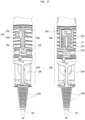
Classifications
-
- A—HUMAN NECESSITIES
- A45—HAND OR TRAVELLING ARTICLES
- A45D—HAIRDRESSING OR SHAVING EQUIPMENT; EQUIPMENT FOR COSMETICS OR COSMETIC TREATMENTS, e.g. FOR MANICURING OR PEDICURING
- A45D20/00—Hair drying devices; Accessories therefor
- A45D20/04—Hot-air producers
- A45D20/08—Hot-air producers heated electrically
- A45D20/10—Hand-held drying devices, e.g. air douches
- A45D20/12—Details thereof or accessories therefor, e.g. nozzles, stands
- A45D20/122—Diffusers, e.g. for variable air flow
Definitions
- the present disclosure relates to a hair dryer that performs a drying function by providing hot air.
- a hairdryer configured to discharge gas through a gas discharge port may be used.
- the hairdryer may be provided therein with a fan unit and the like configured to cause gas to flow.
- the hairdryer including the internal components may be designed for a user to be able to conveniently use the same in consideration of the weight thereof.
- the hairdryer In order to use the hairdryer without wires, the hairdryer must include a battery built therein and must assure an additional space in which the battery is mounted. There is need for a hairdryer which is additionally provided with components such as an ion generator and to which accessories are coupled for the purpose of function enhancement.
- An object of the present disclosure is to provide a diffuser coupled to the front of a hair dryer capable of blowing air evenly over the head, and a hair dryer having the diffuser.
- a diffuser in one aspect of the present disclosure, includes a cone-shaped diffusing case having a rear side removably coupled to a head part of a hair dryer, the diffusing case widening while extending in a forward direction, a discharge cover coupled to a front of the diffusing case and provided with a plurality of discharge holes, and a bridge groove formed in a rear surface of the discharge cover and connecting at least two of the discharge holes.
- the discharge holes may include a first discharge hole, and a second discharge hole disposed further inside than the first discharge hole, wherein the bridge groove may extend from the second discharge hole to the first discharge hole in a radial direction from a center to a periphery.
- the second discharge hole is connected to a plurality of bridge grooves.
- the bridge groove may be connected from one of second discharge holes included in the second discharge hole to one or more first discharge holes included in the first discharge hole.
- the diffuser may further include a third discharge hole disposed in a center of the second discharge hole and not connected to the bridge groove.
- the diffuser may further include a tubular hole protrusion extending forward from the discharge holes, wherein an end of the hole protrusion may include a curve.
- An inner diameter of the hole protrusion may decrease as the hole protrusion extends forward.
- the diffuser may further include a massage protrusion protruding further forward than the hole protrusion.
- the diffusing case may include a ring-shaped gas inlet disposed in a rear surface of the diffusing case, and a magnet disposed in a center of the ring-shaped gas inlet.
- a hair dryer including a head part comprising a gas discharge portion allowing gas introduced from an outside to be discharged therethrough, a handle extending from the head part, and a diffuser removably coupled to the head part, wherein the diffuser allows the gas discharged from the gas discharge portion to be introduced thereinto and discharges the introduced gas to the outside, wherein the diffuser may include a cone-shaped diffusing case having a rear side removably coupled to the head part of the hair dryer, the diffusing case widening while extending in a forward direction, a discharge cover coupled to a front of the diffusing case and provided with a plurality of discharge holes, and a bridge groove formed in a rear surface of the discharge cover and connecting at least two of the discharge holes.
- the diffusing case may include a ring-shaped gas inlet provided in a rear surface of the diffusing case, the gas inlet corresponding to the gas discharge portion, and a first magnet disposed at a center of the ring-shaped gas inlet, wherein the head part may include a second magnet disposed at a center of the discharge portion.
- a hair dryer according to embodiments of the present disclosure allows the heating wires to be wound without interfering with each other.
- the heat of the heater module is not transferred towards a first heater casing on the inner side. Accordingly, damage to parts positioned inside the heater module may be prevented.
- the components of the head part may be stably fixed, and thus may not easily be disassembled by an external impact or the like.
- accessories such as a diffuser may be used to extend the functionality of the hair dryer.
- air may be supplied sufficiently to a first discharge hole disposed on the outside of the diffuser, and thus a larger amount of air than required may be provided.
- embodiments of the present disclosure may improve performance by preventing air from leaking out through openings, such as a button hole or a connector hole, which results in lower pressure.
- a hair dryer may reliably hold a power cable such that the power cable is not easily drawn out.
- 'and/or' includes a combination of a plurality of listed items or one of the plurality of listed items.
- 'A or B' may include 'A', 'B', or 'both A and B'.
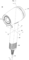
- FIG. 1 illustrates a hair dryer 100 according to one embodiment of the present disclosure
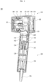
- FIG. 2 is a cross-sectional view showing the interior of the hair dryer 100, taken along line A-A of FIG. 1
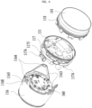
- FIG. 3 is an exploded perspective view of the hair dryer 100 according to one embodiment of the present disclosure.
- the hair dryer 100 includes a head part 110 and a handle 120, as shown in FIG. 1 .
- the head part 110 includes a gas discharge portion 113 through which gas introduced from the outside is discharged.
- the head part 110 may have a gas flow path therein through which gas flows, as shown in FIG. 2 .
- the gas flow path may be formed inside the head part 110 and inside the handle 120, and may be defined as an area extending from a gas inlet 1285 to the gas discharge portion 113.
- the head part 110 may have a shape extending in parallel with the gas discharge direction of the gas discharge portion 113, and may be arranged to have various cross-sectional shapes, such as a circular or polygonal shape.
- Gas may be introduced from the outside through the gas inlet 1285 provided in the handle 120.
- the introduced gas may flow along the gas flow path and be discharged to the outside through the gas discharge portion 113 provided in the head part 110.
- the handle 120 may extend from the head part 110. Referring to FIGS. 1 and 2 , the handle 120 is shown to extend downward from the head part 110. The downward direction does not necessarily mean 90° from the lower portion of the head part 110, and may extend obliquely downward as shown in FIG. 2 .
- the heater, fan motor 151, and fan are disposed in the head part, resulting in a heavy weight of the head part.
- the heavy weight of the head part causes strain on the wrist of the user when the user uses the hair dryer while holding the handle. Therefore, the hair dryer of the present disclosure intends to minimize the strain on the wrist of the user by shifting the fan motor 151 and the fan to the handle.
- the handle 120 may be integrated with the head part 110 or may be fabricated separately and coupled to the head part 110. When the handle 120 is fabricated separately from the head part 110 and coupled to the head part 110, it may have a connecting frame 112 connecting the head part and the handle.
- An upper end of the connecting frame 112 of the present embodiment may be coupled to the head housing 111 and a lower end thereof may be coupled to the handle frame 126. To enhance the coupling effect, the connecting frame 112 may be integrated with the head housing 111.
- the portion between the head housing 111 and the connecting frame 112 is where the direction of extension changes, where the airflow in the internal flow path changes. It is also the most vulnerable to external impact. If the connecting frame 112 is integrated with the handle frame 126 and fastened to a lower portion of the head housing 111, it is likely to be broken.
- the connecting frame 112 and the head housing 111 are integrated, and the connecting frame 112 and the handle frame 126 are fastened separately.
- a handle housing 128 may cover the connecting frame 112 and the handle frame 126 together and reinforce the fastening between the connecting frame 112 and the handle frame 126.
- the handle 120 may be a portion that is held in hand by a user, and may be formed in a cylindrical shape for gripping.
- a small fan motor 151 may be used to reduce the diameter of the handle to facilitate gripping.
- the up-down direction may be defined with respect to the handle 120.
- the handle 120 may have a shape extending downward from the head part 110, with the head part 110 positioned at the top.
- the front-to-back direction may be defined with respect to the direction of extension of the head part.
- the gas discharge portion 113 is the front and the opposite side is the rear.
- a display with a touch function for indicating the state of the hair dryer and for operation by a user may be disposed on the rear.
- the hair dryer 100 includes a blower fan 155 configured to move gas and to regulate the speed of the discharged gas discharged through the gas discharge portion 113.
- the blower fan 155 is disposed in the gas flow path to move the gas, and may be arranged inside the head part 110 or inside the handle 120.
- the hair dryer 100 has the blower fan 155 located in the head part 110, and thus the fan of the blower fan 155 is relatively large.
- the blower fan 155 of the present embodiment is disposed in the handle 120. Since the diameter of the handle 120 is smaller than the head part 110, the size of the blower fan 155 is also reduced.
- the RPM of the fan motor 151 may be increased to rotate the fan at a high speed to create a flow of air into the gas flow path.
- the blower fan 155 operating at 100,000 rpm may create sufficient air flow despite the small size of the fan.
- the hair dryer 100 may include a battery module (not shown) to enable cordless operation. Since the battery module may increase weight and reduce usability if placed in the head part 110, it may be disposed in the handle 120. Since the battery module weighs more than the blower fan 155 disposed in the handle 120, the battery module may be disposed in the lower portion of the handle 120 and the blower fan 155 may be disposed in the upper portion of the handle 120.
- a heater module 160 may be provided in the head part 110 to adjust the temperature of the discharged gas.
- the heater module 160 may be provided in various shapes, and may be arranged at various positions.
- FIG. 2 schematically illustrates the heater module 160 provided inside the head part 110.
- the heater module 160 may heat the gas by generating heat by a current provided to a coil-shaped resistor.
- the resistor of the heater module 160 may not necessarily be in the shape of a coil, and may be of various types to regulate the temperature of the gas, such as a thermoelectric element.
- the operation of the hair dryer 100 according to one embodiment of the present disclosure, with gas flow, is schematically described as follows.
- the user may operate the power button disposed on the handle 120.
- the blower fan 155 is operated and gas is drawn into the hair dryer 100 through the gas inlet 1285.
- the gas introduced through the gas inlet 1285 is forced by the blower fan 155 along the gas flow path to move to the head part. Then, it passes through the heater module 160 and the temperature of the gas rises.
- the heated gas may be discharged from the gas discharge portion 113 and provided to the user. In this process, the flow rate of the gas in the gas flow path may be adjusted by the blower fan 155 and the temperature may be adjusted by the heater module 160.
- the hair dryer 100 may include a substrate module 131, a display substrate 134, and a button substrate 1423 as a controller.
- the controller may be connected to the blower fan 155, the heater module 160, the power button, the operation part, and the like to control these components.
- the operation modes of the blower fan 155 and the heater module 160 may be controlled by operating the button portion 142 on the handle 120 or the display 141 on the rear surface of the head part 110, or may be automatically controlled according to an operation mode preset in the controller.
- the gas inlet 1285 may include a plurality of gas inlets 1285 formed in a handle case 210, and the gas flow path may include a first flow path disposed in the handle 120 and extending up and down the handle 120, and a second flow path disposed in the head part 110 and extending horizontally.
- the first flow path and the second flow path may be arranged in an inverted L-shape, and a pressure compensation flow path may be provided to prevent the flow rate from decreasing in a bent portion of the gas flow path.
- the pressure compensation flow path may contain a sufficiently large space or be gently sloped to change the direction of the flow path.
- the pressure compensation flow path of this embodiment may have a wide space, as a large space is required to form a smooth flow path.
- the flow direction may be changed with minimized decrease in flow rate by utilizing the space inside the connecting frame 112 and the space between the substrate part and the heater module.
- the head part may include a cylindrical head housing 111 defining an exterior and a head frame 115 disposed inside the head housing 111.
- the head housing 111 is disposed such that the cylinder thereof is arranged facing in a front-to-back direction, and may be configured such that the diameter of the cylinder is unequal at the front and back and smaller at the front.
- the heater module 160, the substrate module 131, and the display 141 are mounted on the head frame 115.
- the head frame 115 may include a plurality of frames 116, 117, and 118, which may be joined together and inserted into the head housing 111.
- the head frame 115 may include a heater frame 116 on which the heater module is mounted, a substrate frame 117 on which the substrate is mounted, and a cover frame 118 that is fastened to the rear surface of the head housing 111 and constitutes the rear surface of the head part and on which the display 141 is mounted.
- FIG. 4 is an exploded perspective view of the internal structure of the head part 110 of the hair dryer 100 according to one embodiment of the present disclosure.
- the head part may include a heater module 160 inserted into the heater frame 116, a substrate module 131 inserted into the substrate frame 117, a cover frame 118 coupled to the rear surface of the head part to define an exterior, and a display 141 provided on the rear surface of the cover frame 118.
- Components are fixed to the frames 116, 117, and 118.
- the frames 116, 117, and 118 may be coupled to each other by a hook structure.
- the heater frame 116 may be formed to enclose the heater module 160 and may serve to block heat from the heater from being transferred laterally. Accordingly, the heater frame 116 may have a cylindrical shape that surrounds the entire outer circumferential surface of the heater module 160 and may be in close contact with the inner circumferential surface of the head housing 111.
- the heater frame 116 may include a hook bracket 1163 extending in a backward direction and may be engaged with a hook 1178 of the substrate frame 117 using a hook 1164 formed at an end of the hook bracket 1163.
- the cover frame 118 may be fastened to the substrate frame 117, and may be fastened to the heater frame 116 by means of the hook 1164 located at the end of the hook bracket 1163.
- the heater frame 116, the substrate frame 117, and the cover frame 118 may be coupled together.
- FIG. 5 is a view illustrating an example of the coupling of the head housing 111 of the hair dryer 100 with the head frame 115 of FIG. 4 including the plurality of frames 116, 117, and 118 hooked together, according to one embodiment of the present disclosure.
- the assembled head frame 115 may be inserted from the rear side of the head housing 111 and fixed inside the head housing 111, as shown in FIG. 5 .
- the head frame 115 may be rotated in a clockwise or counterclockwise direction (first direction, 2) to fix the head housing 111 and the head frame 115 after being inserted (1) from the rear side of the head housing 111. Thereby, the head frame 115 and the head housing 111 are fastened.
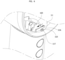
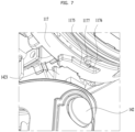
- FIGS. 6 and 7 are views illustrating a fastening structure of the hair dryer 100 according to one embodiment of the present disclosure, wherein FIG. 6 is a view showing an inner surface of the head housing 111 and FIG. 7 is a view showing an outer circumferential surface of the head frame 115.
- the fastening structure illustrated in FIGS. 6 and 7 may include a coupling rib 1115, coupling slots 1165 and 1175, a catch groove 1116, a catch protrusion 1176, a fixing groove 1117, and a fixing protrusion 1177.
- the coupling rib 1115 of the head housing 111 of FIG. 6 is inserted into the coupling slot 1175 of the head frame 115 of FIG. 7 .
- the catch groove 1116 of the head housing 111 of FIG. 6 and the catch protrusion 1176 of the head frame 115 of FIG. 7 are coupled, and the fixing groove 1117 of the head housing 111 of FIG. 6 and the fixing protrusion 1177 of the head frame 115 of FIG. 7 are coupled.
- coupling rib 1115, catch groove 1116, and fixing groove 1117 are shown as being disposed in the head housing 111, and the coupling slot 1175, catch protrusion 1176, and fixing protrusion 1177 are shown as being disposed on the outer circumferential surface of the head frame 115 in this embodiment, the positions thereof may be alternated.
- the head frame 115 may be inserted (1) from the rear surface of the head housing 111 and then rotated in a first direction (2) to be fastened.
- the coupling rib 1115 When inserted from the rear side (1), the coupling rib 1115 may be moved until it reaches one open side of the coupling slot 1175. Then, when the head frame 115 is subsequently rotated in the first direction (2), the coupling rib 1115 may be inserted into the coupling slot 1175 to immobilize the back-and-forth movement of the head frame 115 and the head housing 111.
- the coupling rib 1115 may include a structure that locks the coupling rib 1115 once it reaches the end of the coupling slot 1175.
- the coupling rib 1115 may include a catch structure (hooks 1164 and 1178 and hook grooves 1174 and 1188) at the point where the rotation is completed to prevent the coupling rib 1115 from leaving the coupling slot 1175.
- the recessed catch groove 1116 may be formed in the coupling rib 1115 and the catch protrusion 1176 may be formed in the coupling slot 1175 at a position corresponding to the catch groove 1116 such that the coupling rib 1115 may be fixed to the coupling slot 1175 as the catch protrusion 1176 is inserted into the catch groove 1116.
- the coupling rib 1115 may further include a fixing protrusion 1177 and a fixing groove 1117 to enhance the fastening.
- the fixing protrusion 1177 and fixing groove 1117 may be disposed adjacent to the coupling rib 1115 and coupling slot 1175, as shown in FIGS. 6 and 7 , such that the fixing protrusion 1177 and fixing groove 1117 may be coupled when the coupling rib 1115 is fully inserted into the coupling slot 1175 and the catch groove 1116 and catch protrusion 1176 are coupled.
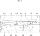
- FIG. 8 is a cross-sectional view illustrating a fastening structure of the head housing 111 and the head frame 115 of the hair dryer 100 according to one embodiment of the present disclosure.
- FIG. 6 is a cross-sectional view of the coupling rib 1115, coupling slot 1175, fixing groove 1117, and fixing protrusion 1177 portions, showing the coupling rib 1115 inserted into the coupling slot 1175 and the fixing protrusion 1177 inserted into the fixing groove 1117.
- the catch protrusion 1176 is inserted into the catch groove 1116.
- the coupling rib 1115 may be provided on the lower side as well as on the upper side of the head housing 111. Due to the narrow space on the lower side where the connecting frame 112 is disposed, only one coupling rib 1115 is provided on the lower side as shown in FIG. 6 , whereas the coupling rib 1115 on the upper side may be arranged in pairs in a front-to-back direction as shown in FIG. 5 .
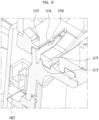
- FIG. 9 is an enlarged view illustrating an upper fastening structure of the head frame 115 of the hair dryer 100 according to one embodiment of the present disclosure.
- the coupling slot 1175 positioned on the lower side may be formed in the substrate frame 117, and the coupling slots 1175 engaging with a pair of coupling ribs 1115 positioned on the upper side may be provided, one in the substrate frame 117 and one in the heater frame 116.
- the coupling between the head frame 115 and the head housing 111 may be enhanced.
- the cover frame 118 may not be directly fastened to the head housing 111, but may be secured by being coupled to the substrate frame 117.
- a sealing member provided on the outer circumferential surface of the cover frame 11 allows the cover frame to closely contact the inner circumferential surface of the head housing 111 to seal the rear surface of the head housing 111.
- the inner surface of the head housing 111 may not contact the outer surface of the heater frame 116 because the rear face of the head housing 111 is wide.
- the coupling rib 1115 formed on the inner surface of the head housing 111 protrudes, the insertion of the head frame 115 may be impeded by the coupling rib 1115.
- the head frame 115 may be provided with a guide slope 1168 including an inclined surface to allow the coupling rib 1115 to move.
- the guide slope 1168 may be formed on the head frame 115 and may be configured to recess from the outer circumferential surface of the head frame 115 toward the rear side.
- the guide slope 1168 may extend forward from an open end of the coupling slot 1175. As the coupling slot 1175 is formed in the substrate frame 117, the guide slope 1168 may be formed on the outer circumferential surface of the heater frame 116.
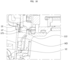
- FIGS. 9 and 10 are cross-sectional views illustrating a fastening structure of the head housing 111 and the head frame 115 of the hair dryer 100, according to one embodiment of the present disclosure.
- FIG. 9 shows an upper portion of the head part 110 and
- FIG. 10 shows a lower portion of the head part 110.
- the hook 1164 of the heater frame 116 and the hook groove 1174 of the substrate frame 117 are fastened, and the hook 1178 of the substrate frame 117 and the hook groove 1188 of the cover frame 118 are fastened.
- a plurality of hooks 1164, 1178 may be provided along the outer circumferential surface, and the positions thereof are not limited to the upper or lower portion.
- the upper portion of the head housing 111 has a pair of coupling ribs 1115 as described above, and the coupling ribs 1115 may be coupled with the coupling slot 1175 disposed in the heater frame 116 and the coupling slot 1175 formed in the substrate frame 117, respectively.
- the lower portion of the head part 110 shown in FIG. 12 has a fastening structure disposed at a rear position where the connecting frame 112 is disposed. After the head frame 115 is coupled to the head housing 111, a button substrate on which the button portion 142 is mounted may be inserted into the connecting frame 112.
- the upper side of the button substrate 1423 may overlap the head frame 115, as shown in FIG. 10 . In terms of position, it may be in contact with the front of the substrate frame 117, and the button substrate may secure the head frame 115.
- FIG. 11 is a view illustrating a separator 164 of the hair dryer 100 according to one embodiment of the present disclosure.
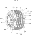
- FIG. 11 is a perspective view of the heater module 160 seen from the front, in which a fourth heater case 166 positioned at the front has been removed.
- the heater module 160 may include a pair of heater cases 163 and 165 of different diameters that are arranged overlapping each other, and the space between the heater cases 163 and 165 may be used to define a flow path for airflow.
- the inner space of the first heater case 163, which is positioned inside, may be used to dispose an ionizer 168 that supplies ions.
- the heater module may include a third heater case 166 covering the rear of the first heater case 163 and a fourth heater case 166 covering the front thereof.
- the fourth heater case 166 may include an open hole 1661 in the front to allow ions generated by the ionizer 168 inside the first heater case 163 to be supplied.
- the fourth heater case 166 may be provided with a magnet or the like for attachment and detachment of additional accessories to be mounted in the gas discharge portion 113.
- an accessory board (not shown) may be mounted for electrical connection to power or control the accessories.
- the heater module 160 may be further provided with a temperature sensor 169 to detect the temperature of the air discharged to the gas discharge portion 113, such that the operation of the heater module 160 may be stopped when the temperature of the discharged air is excessively high as to cause burns.
- the first to fourth heater cases 163, 165, 166, and 167 may include an insulating material to prevent heat transfer from the heating wire 161 to the surrounding devices and outside of the head housing 111.
- a representative example may include mica, which is not only insulative but also fire resistant, and thus may prevent a fire from occurring.
- a heating wire 161 may be disposed to increase the temperature of the air passing through the space between the first heater case 163 and the second heater case 165 positioned on the outside.
- the heating wire 161 shown in FIG. 9 may be a coiled heating wire 161 and may be wound around the circumference of the first heater case 163.
- the heating wire 161 may take various forms other than the coil, such as a zigzag bent tape type.
- a separator 164 may be used to maintain the spacing between the respective heating wires 161 and to maintain a constant separation space between the first heater case 163 and the second heater case 165.
- the separator 164 is disposed radially, with an inner side facing the first heater case 163 and an outer side facing the second heater case 165.
- FIG. 12 is a view illustrating the separator 164 of the hair dryer 100 according to one embodiment of the present disclosure.
- the lower portion is an inner end facing the first heater case 163 and the upper portion is an outer end facing the second heater case 165.
- FIG. 12-(a) illustrates a first separator 1641 and FIG. 12-(b) illustrates a second separator 1642.
- the first separator 1641 on which the first heating wire 1611 is wound and the second separator 1642 on which the second coil is wound may be alternately disposed as shown in FIG. 9 . As shown in FIG. 9 , the first separator 1641 may not be in direct contact with the second heater case 165, but the upper side of the second separator 1642 may contact the inner surface of the second heater case 165 to fix the position of the second heater case 165.
- the first separator 1641 is provided with a plurality of deeply recessed first grooves 1641a.
- a second groove 1641b having a shallower depth than the first groove 1641a may be disposed between the first grooves 1641a.
- a first heating wire 1611 may be disposed in the first groove 1641a and a second heating wire 1612 may be disposed in the second groove 1641b.
- the first heating wire 1611 and the second heating wire 1612 may be positioned at different distances from the center of the heater module 160.
- the first separator 1641 has the first groove 1641a and the second groove 1641b and the height thereof is less than that of the second separator 1642 (h1 ⁇ h2).
- the second separator 1642 is taller than the first separator 1641 and has a third groove 1642a formed in a lower portion thereof for the first heating wire 1611 to extend through.
- the top (outer end) of the second separator 1642 may include a fourth groove 1642b in which the second heating wire 1612 is disposed.
- the third groove 1642a and the fourth groove 1642b are spaced apart from each other such that the first heating wire 1611 and the second heating wire 1612 do not overlap.
- FIG. 13 is a view illustrating winding of the first heating wire 1611 of the heater module 160 of the hair dryer 100 according to one embodiment of the present disclosure.
- first separators 1641 may be disposed on the first heater case 163 at equally spaced intervals.
- the third heater case 166 which covers the rear surface of the first heater case 163, may include a separator fixing groove 1671 for fixing the separator 164, as shown in FIG. 13 .
- the first heating wire 1611 is wound in the first groove 1641a of first separator 1641.
- a start point 1611a of the first heating wire 1611 is connected to a first electrode 1613 extending to the rear of the heater module 160 and an end point 1611b thereof is disposed at the front of the heater module 160.
- the first heating wire 1611 is spirally wound from the rear where the third heater casing 166 is disposed, toward the front. Due to this spiral structure, the positions of the first grooves 1641a of the plurality of first separators 1641 may be slightly misaligned.
- the start point 1611a and end point 1611a of the first heating wire 1611 are disposed on the first separator 1641 on the upper side.
- first separator 1641 on the upper side may include four first grooves 1641a, while the other first separators 1641 may include three first grooves 1641a.
- the number of first grooves 1641a is not limited thereto and may vary depending on the thickness or arrangement of the first heating wire 1611.
- FIG. 14 is a view illustrating coupling of the second separator 1642 of the heater module 160 of the hair dryer 100 according to one embodiment of the present disclosure.
- the second separator 1642 may be disposed in between two first separators 1641.
- the second separator 1642 may be fitted into a separator fixing portion 1671 formed in the third heater casing 166.
- the first heating wire 1611 may extend through the third groove 1642a.
- a horizontal position of the first heating wire 1611 may be fixed and the first heating wire 1611 may be restricted from moving toward the second heater case 165 where the second heating wire 1612 is positioned.
- FIG. 15 is a view illustrating winding of the second heating wire 1612 of the heater module 160 of the hair dryer 100 according to one embodiment of the present disclosure.
- the second heating wire 1612 is spirally wound such that the second heating wire 1612 is disposed in the fourth groove 1642b of the second separator 1642 and the second groove 1641b of the first separator 1641.
- the start point 1612a of the second heating wire 1612 may be disposed at the front of the heater module 160 and the end point 1612b of the second heating wire 1612 may be disposed at the rear of the heater module 160.
- the first heating wire 1611 and the second heating wire 1612 may be connected in parallel to be driven independently. In this embodiment, however, the first heating wire 1611 and the second heating wire 1612 may be connected in series.
- a bimetal 1615 and a fuse 1616 may be disposed between the first heating wire 1611 and the second heating wire 1612 to prevent temperature from rising above a specific temperature, thereby preventing a fire.
- the bimetal 1615 may change its shape and release the connection between the first heating wire 1611 and the second heating wire 1612 when the temperature rises above a first reference temperature, and reconnect the wires when the temperature decreases.
- the fuse 1616 may physically blow to prevent overheating.
- the end point 1612b of the second heating wire 1612 is connected to the second electrode 1614 at the rear of the heater module 160.
- the first electrode 1613 and the second electrode 1614 may be disposed on the third heater casing 167 and connected to the substrate module 131, which may control the heater module 160.
- the second heater case 165 may be added such that the heating wire 161 is disposed in the flow path between the first heater case 163 and the second heater case 165.
- the heater module 160 is inserted into the heater frame 116 as shown in FIG. 3 .
- the heater module 160 of the present disclosure may employ the separator 164 to prevent contact between the heating wires 161 in a confined space. Thus, a stable heater module 160 may be implemented.
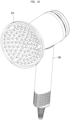
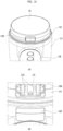
- FIG. 16 is a view illustrating a diffuser mounted on the hair dryer 100 according to one embodiment of the present disclosure.
- an accessory 210 may be attached to the hair dryer 100.
- the diffuser 210 which is shaped with smaller discharge holes, may concentrate the airflow to a specific location for quick drying of a small area. Alternatively, it may redirect the airflow to form curls in the hair.
- the diffuser 210 shown in FIG. 16 is a device that disperses the air from the gas discharge portion 113 of the hair dryer 100 over a wide area to dry the scalp. By placing the diffuser 210 in contact with the scalp, the air from the hair dryer 100 may be supplied directly to the scalp to remove moisture from the scalp.
- the diffuser 210 may be trumpet-shaped, with a front end that is wider than the diameter of the portion that is coupled to the gas discharge portion 113 of the hair dryer 100. Since the scalp senses heat more readily than the hair, there is a risk of burns if hot air is concentrated in a particular position. Therefore, the diffuser 210 for drying the scalp may distribute the hot air over a wide area to lower the temperature while achieving quick scalp drying.
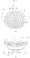
- FIG. 17 is a front view and a cross-sectional view of the diffuser 210 according to one embodiment of the present disclosure, wherein (a) is a front view and (b) is a cross-sectional view taken along line C-C in (a).
- the diffuser 210 may include a diffusing case 216 having a rear side removably coupled to the head part 110 of the hair dryer 100, the diffusing case having a cone shape that widens as it extends forward, and a discharge cover 211 coupled to the front of the diffusing case 216 and provided with a plurality of discharge holes 212.
- the diffusing case 216 may include a magnet or ferromagnet 217 for coupling with a magnet disposed in the gas discharge portion 113 of the hair dryer 100.
- the rear surface of the diffusing case 216 is provided with a donut-shaped opening 2165 corresponding to the shape of the gas discharge portion 113, and the front thereof is coupled with the discharge cover 211.
- the discharge cover 211 may have a concave shape corresponding to a head, with a recessed center and protruding ends.
- a plurality of discharge holes 212 may be formed in the discharge cover 211 and may be disposed radially as shown in (a) of FIG. 17 .
- the size of the discharge holes 212 may become smaller as they are spaced apart from the center of the discharge cover 211. Thus, the largest amount of air is discharged from the center portion of the discharge cover 211 and the amount of air discharged from the ends is small.
- the air volume becomes smaller toward the ends of the discharge cover 211. If the discharge holes 12 at the ends have the same size as those at the center, the flow rate will decrease. Therefore, the size of the discharge holes 2121 may decrease from the center to the ends of the discharge cover 211.
- the discharge hole 212 may be further provided with a protrusion 213 extending forward from the discharge hole 212 to guide air to be quickly discharged along a straight line.
- the extension 213 may be shaped like a tube or pipe with a hole in the center and may have a tapered shape with a smaller hole diameter (inner diameter) at the front end.
- a massage protrusion 214 that protrudes further than the protrusion 213 may be further provided such that the discharge hole 212 is positioned a specific distance away from the scalp.
- the end of the massage protrusion 214 may directly contact the scalp while the end of the protrusion 213 is kept a predetermined distance from the scalp.
- Three or more massage protrusions 214 may be provided for balance when coming into contact with the user's head and may include a material such as silicone to minimize irritation to the scalp.
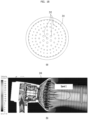
- FIG. 18 shows a rear view and simulation results illustrating the performance of the diffuser 210 according to one embodiment of the present disclosure.
- the rear surface of the discharge cover 211 is simply provided with only the discharge holes 212. In this case, most of the air discharged from the gas discharge portion 113 is discharged into the discharge holes 212 located in the center, and thus the speed and volume of air flow in the center portion is higher than in the periphery, as shown in (b) of FIG. 18 .
- the diffuser 210 is intended to diffuse air discharged through the gas discharge portion 113 of the head part 110, and thus air should be supplied even to the discharge holes 212 located at the outer portion of the discharge cover 211.
- a bridge groove 215 may be provided to guide air up to the discharge holes 212 located at the outer portion of the discharge cover 211.
- FIG. 19 shows a rear view and a simulation result illustrating the performance of a diffuser 210 according to another embodiment of the present disclosure.
- the bridge groove 215 is a recess extending radially on the rear surface of the discharge cover 211 to connect two or more discharge holes 212.
- the discharge hole 212 located in the outer side may be referred to as a first discharge hole 2121 and the discharge hole 212 located in the inner side may be referred to as a second discharge hole 2122.
- the bridge groove 215 may be provided to connect the first discharge hole 2121 and the second discharge hole 2122.
- the second discharge holes 2122 are positioned further inside than the first discharge holes 2121 and are therefore fewer in number.
- multiple bridge grooves 215b may extend from one second discharge hole 2122 and multiple first discharge holes 2121 may be connected to one bridge groove 215.
- the second discharge holes 2122 and the first discharge holes 2121 are distinguished from each other by their relative positions on the discharge cover 211.
- the second discharge hole 2122 is positioned further inward than the first discharge hole 2121.
- the gas discharge portion 113 of the head part 110 is open in a donut shape. Therefore, the strongest airflow may be supplied to a position slightly spaced apart from the actual center portion. Some air is discharged through the discharge holes 212 at the peripheral portion of the donut shape, and the remaining air is supplied through the discharge holes 212 at the center and outer portions.
- the second discharge hole 2122 which is the start of the bridge groove 215, may be positioned in a straight line with the gas discharge hole 113 to allow air to reach the circumference of the discharge cover 211.
- a third discharge hole 2123 may be further provided that is located inward of the second discharge hole 2122 and is not connected to the bridge groove 215.
- the third discharge hole 2123 is supplied with air from the periphery and naturally collects and discharges a large amount of air without the bridge groove 215, making the bridge groove 215 unnecessary.
- the bridge groove 215 may extend from the second discharge hole 2122, which is slightly spaced apart from the center, toward the first discharge hole 2121, which is positioned at the outer portion of the discharge cover 211.
- bridge grooves 215c may connect between the bridge grooves 215 disposed at the outer portion.
- Embodiments may also include bridge grooves (not shown) that branch off of one bridge groove 215 in the form of branches.
- FIG. 20 is graphs depicting the performance of the diffusers 210 with and without bridge grooves 215 according to one embodiment of the present disclosure.
- the circled areas in the middle represent the center portion, and increasing numbers (+/- indicates a direction) indicate approaching the outer portion.
- air may be guided to the discharge holes 212 disposed in the outer portion through the bridge groove 215 connecting between the discharge holes 212.
- air may be supplied evenly to the scalp.
- the scalp drying speed may be improved.
- hot air is used to accelerate drying, it may not be concentrated in a specific area to cause burns.
- the scalp may be dried safely.
- FIGS. 21 and 22 are views illustrating a connector module 133 of the hair dryer 100 according to one embodiment of the present disclosure.
- the hair dryer 100 of the present disclosure may be controlled in various modes beyond simply adjusting the speed of the heater module 160 and the fan module 155.
- hot air may need to be supplied in different ways depending on the condition of the user's scalp, such as curly hair, thin hair, and a lot of hair.
- hot air and airflow intensity may be controlled according to a specific mode, such as a scalp drying mode or an intensive drying mode.
- the hair dryer 100 of the present disclosure may be provided with a display 141 on the rear surface thereof to provide an interface for easy use by a user and to provide videos such as user guides.
- a separate controller may be provided, and may include a substrate module 131 and a display substrate 134 on which an IC is mounted.
- a substrate module 131 may be provided, and may include a substrate module 131 and a display substrate 134 on which an IC is mounted.
- an external terminal such as a computer.
- a connector terminal 1331 is needed to connect to the external terminal.
- the connector terminal 1331 should be exposed to the outside. However, since it is not frequently utilized like the connector terminal 1331 of other electronic devices, it is advantageous in appearance and function to expose the terminal for use by opening the cover only when necessary.
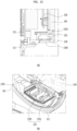
- a connector module 133 including the connector terminal 1331 may be provided at the bottom of the head part 110 as shown in FIG. 21 , and a connector hole 1184 may be formed in the head housing 111 for exposing the connector module 133.
- a connector cover 1185 coupling to the connector hole 1184 may be configured to prevent the connector terminal 1331 from being exposed to the outside in normal times.
- the connector module 133 may be arranged in the head part 110 to minimize wiring. It may be disposed on the rear side of the handle 120 so as to be spaced apart from the heater module 160.
- It may be disposed in a lower portion of the hair dryer 100 so as to be minimally exposed to the view of the user in normal times.
- the hair dryer 100 includes a flow path therein, and the air introduced into the gas inlet should be discharged through the gas discharge portion 113. If an opening is formed between the gas inlet and the gas discharge portion 113, the performance of the hair dryer 100 may be degraded due to a decrease in the flow rate.
- a connector gasket 1335 may be provided to tightly contact the periphery of the connector hole 1184.
- FIG. 22 is a cross-sectional and perspective view illustrating a portion of the connector module 133, wherein the connector gasket 1335 may be configured to surround the perimeter of the connector module 133. An end of the connector gasket 1335 may be in close contact with the head housing 111 and may be disposed along the circumference of the connector hole 1184.
- the connector module 133 may be positioned under the display substrate 134 mounted on the cover frame 118, and may be arranged perpendicular to the display substrate 134 as the display substrate 134 is disposed to face in a front-to-back direction, but the connector module 133 is positioned around the perimeter of the cover frame 118.
- FIG. 23 is a cross-sectional view of the connecting frame 112 of the hair dryer 100 according to one embodiment of the present disclosure wherein (a) is a cross-sectional view taken along line D-D in FIG. 2 and (b) is a cross-sectional view taken along line E-E in FIG. 2 .
- the connecting frame 112 extends downward from a connection hole formed in a lower portion of the head housing 111.
- the connecting frame 112 may be integrated with the head housing 111 and may be connected to the handle frame 126.
- the fastening structure may overlap, making the connection portion thicker.
- the position of connection between the head part 110 and the handle 120 is also weak in terms of rigidity, and thus the connecting frame 112 is extended from the connection hole to place the position of connection with the handle frame 126 in the middle of the handle 120.
- the fan motor 151 and the blower fan 155 which are coupled to the upper portion of the handle frame 126, are inserted into the lower portion of the connecting frame 112 as shown in FIG. 23 .
- the inner space of the connecting frame 112 serves as a flow path through which air drawn in by the blower fan 155 is supplied to the heater module 160 disposed at the upper portion.
- a button portion 142 may be disposed on the connecting frame 112.
- the button portion 142 may be used to turn on/off the power, turn on/off the fan motor 151, turn on/off the heater module 160, or control the intensity of the air flow and the heater.
- a display 141 may be provided to provide various interfaces. However, the power is needed to activate the display 141, and thus a physical button may be used as the power button.
- the button part 142 may be provided as a user input unit that the user can operate with the hand holding the handle 120 without looking at it.
- the button portion 142 may be disposed at, but not limited to, the front and rear of the handle 120 as shown in (a) of FIG. 23 . It may be disposed on the left and right sides. Since an excessive number of buttons limits control without looking, the present embodiment may have a power button at the front and buttons for controlling ON/OFF of the fan motor 151 and heater module 160 at the rear.
- the handle housing 128, which surrounds the connecting frame 112 and the handle frame 126, may include a button hole 1124 for exposing the button portion 142 to the outside, and includes a button cover 1421 inserted into the button hole.
- the button cover 1421 has a front surface exposed to the outside through the button hole 1124, and an inner surface contacting a switch 1422 mounted on the button substrate 1423, as shown in FIG. 23 .
- a sealing member may be provided.
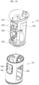
- FIG. 24 is an exploded perspective view of the connecting frame 112 of the hair dryer 100 according to one embodiment of the present disclosure.
- the connecting frame 112 may have the button module 142 mounted thereon and may be open on the sides to facilitate connection of wiring structures extending from the handle frame 126.
- It may include a first ring frame 1121 extending downward from the extension hole, a plurality of pillar frames 1122 extending downward from the first ring frame 1121, and a second ring frame 1123 connecting the lower ends of the plurality of pillar frames 1122 and coupled to the handle frame 126.
- the pillar frames 1122 may be disposed on the front, rear, left and right sides such that the openings are formed on the front, rear, left and right sides.
- a button bracket 1124 may be further provided in addition to front and rear openings 1125 as an additional structure in which the button module 142 may be mounted. Wires may be arranged through the left and right side openings 1125, and the button module 142 may be inserted into and secured to the button bracket 124 of the connecting frame 112.
- the button gasket 114 may be disposed only in the portion corresponding to the button hole 1124 to prevent air from leaking through the button hole 1124, but air may leak through the gap between the connecting frame 112 and the handle housing 128. As shown in FIG. 24 , the button gasket 114 may be formed in a cylindrical shape to surround the connecting frame 112 to seal the gap between the handle housing 128 and the connecting frame 112.
- the button gasket 114 may be fitted onto the connecting frame 112 from a lower side to an upper side.
- the tube-shaped button gasket 114 may include an opening 1145 that is stretchable in order to prevent the button gasket from being torn.
- the opening 1145 may allow the diameter of the button gasket 114 to be easily increased to fit the button gasket onto the connecting frame 112.
- the button gasket 114 may include a switch hole 1141 in a position corresponding to the switch 1422 of the button module 142 such that the switch 1422 contacts an inner surface of the button cover 1421.
- the inner surface of the button gasket 114 may closely contact the button substrate 1423.
- the button cover 1421 inserted into the button hole 1124 may include a wing portion so as not to be displaced from the button hole 1124, and thus a concave portion 1142 may be formed at a position corresponding to the switchhole 1141 to allow the wing portion to be seated.
- the button gasket 114 configured to surround the connecting frame 112, may include a curved flow guide on an upper portion thereof, the curved flow guide directed toward the connection hole. By eliminating a step in the connecting frame 112, the air flow may continue uninterruptedly through the connection portion to the head part 110.
- FIG. 25 is an exploded perspective view of the handle 120 of the hair dryer 100 according to one embodiment of the present disclosure.
- the handle frame 126 coupled to the lower portion of the connecting frame 112 may include a first handle frame 1261 and a second handle frame 1262 coupled in a front-to-back direction. While illustrated as being coupled in the front-to-back direction, the handle frames may be coupled in a side-to-side direction.
- the first and second frames may have a symmetrical structure and may be open in a lateral direction to allow air to move into the connecting frame 112 through the gas inlet disposed at the lower end of the handle housing 128.
- the connecting frame 112 may have openings 1266 on the front, rear, left, and right sides and the pillar frames 1122 on the diagonal sides, and the handle frame 126 may have pillar frames 1265 on the front, rear, left, and right sides and openings on the diagonal sides.
- the handle frame 126 may include an upper portion where the fan motor 151 and the blower fan 155 are disposed, and a lower portion that is open to allow air to be introduced.
- the lower portion 126b of the handle frame may allow air to be introduced thereinto and may be coupled with a power cable 136.
- the power cable 136 may include a first cable 1361 and a second cable 1362 connected to the + and - electrodes, respectively. A portion of the power cable exposed to the outside of the hair dryer 100 may be enclosed in a sheath to extend in a single line, and the power cable may be divided inside the handle case.
- a portion of the power cable 136 connected to the lower end of the handle 120 may be at risk of being cut, and thus may be thickened for protection.
- the increased thickness of the sheath may make bending deformation difficult, and thus the power cable may have a wing portion that extends outward, as shown in FIG. 25 .
- FIG. 25 is a view illustrating a method of fastening the handle frame 126 of the hair dryer 100 according to one embodiment of the present disclosure, wherein (a) illustrates the first handle frame 1261 and (b) illustrates the second handle frame 1262 coupled to the first handle frame 1261.
- the first handle frame lower portion 126b may include a pillar frame 1265b that defines a U-shaped inner space and extends in a direction perpendicular to the U-shaped inner space.
- the pair of pillar frames (on the left and right sides in this embodiment) includes the inner space defined by the first handle frame 1261 and the second handle frame 1262 coupled together.
- the front and rear pillar frames are provided for rigidity of the handle frame 126 and may be disposed 90° apart from the pillar frames on the left and right sides.
- the power cable 136 extends through the lower end of the U-shaped inner space.
- the power cable 136 may branch into the first cable 1361 and the second cable 1362, which may extend in opposite directions and extend upward in the U-shaped space, respectively.
- the lower end of the first handle case may include a plurality of cable fixing protrusions 1263 disposed on the upper side of a lower end hole 1282 into which the power cable 136 is inserted.
- the plurality of cable fixing protrusions 1263 may be disposed side-by-side in a lateral direction.
- the first cable 1361 and the second cable 1362 are wound around the different cable fixing protrusions 1263 in an S-shape to be fixed and then extend upward.
- the first cable 1361 and the second cable 1362 extend in different directions. Furthermore, the first cable 1361 and the second cable 1362, tightly wound around the cable fixing protrusions 1263 in an S-shape will not be drawn out even if the portion of the power cable 136 exposed to the outside is pulled out.
- the cable fixing protrusions 1263 around which the first cable 1361 and second cable 1362 are wound may serve not only to secure the power cable 136, but also as a fastening member fastened to the second handle frame 1262, as shown in (b) of FIG. 24 .
- the second handle frame 1262 includes frame coupling holes 1264 formed at positions corresponding to the cable fixing protrusions 1263, and the cable fixing protrusions 1263 are inserted into the frame coupling holes 1264 and fixed to the first handle frame 1261 and the second handle frame 1262.
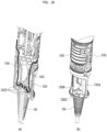
- FIG. 27 is a view illustrating a cable arrangement on the handle frame 126 of the hair dryer 100 according to one embodiment of the present disclosure, wherein (a) and (b) are views from different directions and illustrate a portion of the coupling surface of a first handle case and a second handle case.
- the first cable 1361 and the second cable 1362 extend from the handle frame lower portion 126b to the handle frame upper portion 126a.
- the handle frame upper portion 126a may be disposed on the outer surface of the handle frame 126 as the fan motor 151 is mounted thereon.
- the handle frame 126 has holes formed on both sides to allow the power cable 136 to extend therethrough at the boundary between the upper and lower portions, and the first cable 1361 and the second cable 1362 may each extend through the holes and be positioned on the outer surface of the handle frame upper portion 126a as shown in FIG. 27 .
- the outer surface of the handle frame 126 may include a cable groove in which the power cable 136 is seated, and the power cable 136 may extend into the connecting frame 112 at a point where it is connected to the connecting frame 112.
- FIG. 27-(b) shows the side opposite to that of FIG. 27-(a) .
- a bimetal 137 may be arranged on the outer surface to interrupt operation of the hair dryer 100 upon sensing that the handle 120 is overheated.
- a third cable 1371 and a fourth cable 1374 connected to the bimetal 137 may be disposed on the upper outer surface of the handle frame 126 opposite the first cable 1361 and the second cable 1362.
- the hair dryer 100 allows the heating wires 161 to be wound without interfering with each other.
- embodiments of the present disclosure may prevent heat from the heater module 160 from being transferred to the first heater case 163 on the inner side, thereby preventing damage to any components disposed inside the heater module 160.
- the components of the head part 110 may be stably fixed, and thus may not be easily disassembled by an external impact or the like.
- the functionality of the hair dryer 100 may be increased by using accessories such as the diffuser 210.
- air may be sufficiently supplied to the first discharge hole 2121, which is disposed on the outer portion of the diffuser 210. Accordingly, more air than needed may be provided over a wide area.
- the hair dryer 100 may prevent air from escaping through openings such as the button hole 1124 or connector hole 1184 to reduce pressure. Accordingly, performance may be improved.
- the hair dryer 100 may securely fix the power cable 136 to prevent the power cable 136 from being easily drawn out.
Landscapes
- Cleaning And Drying Hair (AREA)
Abstract
Description
- The present disclosure relates to a hair dryer that performs a drying function by providing hot air.
- When it is intended to remove a desired amount of moisture from hair of a human in a wet state or to style the hair to a desired shape from a current shape, a hairdryer configured to discharge gas through a gas discharge port may be used.
- The hairdryer may be provided therein with a fan unit and the like configured to cause gas to flow. The hairdryer including the internal components may be designed for a user to be able to conveniently use the same in consideration of the weight thereof.
- When a heater module is positioned at a head part and the temperature of a case increases due to the heat generated by the heater module, there may be a risk of burn injury and internal components such as a controller may be affected. Accordingly, there is need for a structure in which the heat generated by the heater module is fully transmitted to air passing through a passage without being transmitted to the outside or other portions.
- In order to use the hairdryer without wires, the hairdryer must include a battery built therein and must assure an additional space in which the battery is mounted. There is need for a hairdryer which is additionally provided with components such as an ion generator and to which accessories are coupled for the purpose of function enhancement.
- An object of the present disclosure is to provide a diffuser coupled to the front of a hair dryer capable of blowing air evenly over the head, and a hair dryer having the diffuser.
- In one aspect of the present disclosure, provided herein a diffuser includes a cone-shaped diffusing case having a rear side removably coupled to a head part of a hair dryer, the diffusing case widening while extending in a forward direction, a discharge cover coupled to a front of the diffusing case and provided with a plurality of discharge holes, and a bridge groove formed in a rear surface of the discharge cover and connecting at least two of the discharge holes.
- The discharge holes may include a first discharge hole, and a second discharge hole disposed further inside than the first discharge hole, wherein the bridge groove may extend from the second discharge hole to the first discharge hole in a radial direction from a center to a periphery.
- The second discharge hole is connected to a plurality of bridge grooves.
- The bridge groove may be connected from one of second discharge holes included in the second discharge hole to one or more first discharge holes included in the first discharge hole.
- The diffuser may further include a third discharge hole disposed in a center of the second discharge hole and not connected to the bridge groove.
- The diffuser may further include a tubular hole protrusion extending forward from the discharge holes, wherein an end of the hole protrusion may include a curve.
- An inner diameter of the hole protrusion may decrease as the hole protrusion extends forward.
- The diffuser may further include a massage protrusion protruding further forward than the hole protrusion.
- The diffusing case may include a ring-shaped gas inlet disposed in a rear surface of the diffusing case, and a magnet disposed in a center of the ring-shaped gas inlet.
- In another aspect of the present disclosure, provided herein is a hair dryer including a head part comprising a gas discharge portion allowing gas introduced from an outside to be discharged therethrough, a handle extending from the head part, and a diffuser removably coupled to the head part, wherein the diffuser allows the gas discharged from the gas discharge portion to be introduced thereinto and discharges the introduced gas to the outside, wherein the diffuser may include a cone-shaped diffusing case having a rear side removably coupled to the head part of the hair dryer, the diffusing case widening while extending in a forward direction, a discharge cover coupled to a front of the diffusing case and provided with a plurality of discharge holes, and a bridge groove formed in a rear surface of the discharge cover and connecting at least two of the discharge holes.
- The diffusing case may include a ring-shaped gas inlet provided in a rear surface of the diffusing case, the gas inlet corresponding to the gas discharge portion, and a first magnet disposed at a center of the ring-shaped gas inlet, wherein the head part may include a second magnet disposed at a center of the discharge portion.
- A hair dryer according to embodiments of the present disclosure allows the heating wires to be wound without interfering with each other.
- Furthermore, according to embodiments of the present disclosure, the heat of the heater module is not transferred towards a first heater casing on the inner side. Accordingly, damage to parts positioned inside the heater module may be prevented.
- Furthermore, according to embodiments of the present disclosure, the components of the head part may be stably fixed, and thus may not easily be disassembled by an external impact or the like.
- Furthermore, according to embodiments of the present disclosure, accessories such as a diffuser may be used to extend the functionality of the hair dryer.
- Furthermore, according to embodiments of the present disclosure, air may be supplied sufficiently to a first discharge hole disposed on the outside of the diffuser, and thus a larger amount of air than required may be provided.
- Further, embodiments of the present disclosure may improve performance by preventing air from leaking out through openings, such as a button hole or a connector hole, which results in lower pressure.
- Furthermore, according to embodiments of the present disclosure, a hair dryer may reliably hold a power cable such that the power cable is not easily drawn out.
-
-
FIG. 1 is a view illustrating a hair dryer according to one embodiment of the present disclosure. -
FIG. 2 is a cross-sectional view illustrating the interior of the hair dryer according to one embodiment of the present disclosure. -
FIG. 3 is an exploded perspective view of the hair dryer according to one embodiment of the present disclosure. -
FIG. 4 is an exploded view of a head part of the hair dryer according to one embodiment of the present disclosure. -
FIG. 5 is a cross-sectional view illustrating an example of the coupling of a head housing and a head frame of the hair dryer according to one embodiment of the present disclosure. -
FIGS. 6 and7 are views illustrating a fastening structure of the hair dryer according to one embodiment of the present disclosure. -
FIG. 8 is a cross-sectional view illustrating a fastening structure of a head housing and a head frame of the hair dryer according to one embodiment of the present disclosure. -
FIGS. 9 and10 are cross-sectional views illustrating a fastening structure of a head housing and a head frame of the hair dryer according to one embodiment of the present disclosure. -
FIG. 11 is a view illustrating a heater module of the hair dryer according to one embodiment of the present disclosure. -
FIG. 12 is a view illustrating a separator of the hair dryer according to one embodiment of the present disclosure. -
FIG. 13 is a view illustrating winding of a first heating wire of a heater module of the hair dryer according to one embodiment of the present disclosure. -
FIG. 14 is a view illustrating coupling of a second separator of a heater module of the hair dryer according to one embodiment of the present disclosure. -
FIG. 15 is a view illustrating winding of a second heating wire of a heater module of the hair dryer according to one embodiment of the present disclosure. -
FIG. 16 is a view illustrating a diffuser mounted on the hair dryer according to one embodiment of the present disclosure. -
FIG. 17 is a front view and a cross-sectional view of a diffuser according to one embodiment of the present disclosure. -
FIG. 18 shows a rear view and a simulation result illustrating the performance of a diffuser according to one embodiment of the present disclosure. -
FIG. 19 shows a rear view and a simulation result illustrating the performance of a diffuser according to another embodiment of the present disclosure. -
FIG. 20 is graphs depicting the performance of diffusers with and without a bridge according to one embodiment of the present disclosure. -
FIGS. 21 and22 are views illustrating a connector of the hair dryer according to one embodiment of the present disclosure. -
FIG. 23 is a cross-sectional view of a connecting frame of a hair dryer according to one embodiment of the present disclosure. -
FIG. 24 is an exploded perspective view of the connecting frame of the hair dryer according to one embodiment of the present disclosure. -
FIG. 25 is an exploded perspective view of a handle of the hair dryer according to one embodiment of the present disclosure. -
FIG. 26 is a view illustrating a method of fastening a handle frame of the hair dryer according to one embodiment of the present disclosure. -
FIG. 27 is a view illustrating a cable arrangement on the handle frame of the hair dryer according to one embodiment of the present disclosure. - Hereinafter, an embodiment of the present disclosure will be described in detail with reference to the accompanying drawings to be easily implemented by those skilled in the art to which the present disclosure belongs.
- However, the present disclosure may be implemented in many different forms and is not limited to embodiments described herein. In addition, in order to clearly describe the present disclosure, components irrelevant to the description are omitted, and like reference numerals are assigned to similar components throughout the specification.
- In this specification, duplicate descriptions of the same components are omitted.
- Further, in this specification, it will be understood that when a component is referred to as being "connected with" another component, the component may be directly connected with the other component or intervening components may also be present. In contrast, it will be understood that when a component is referred to as being "directly connected with" another component in this specification, there are no intervening components present.
- Further, in this specification, the terminology used herein is for the purpose of describing a specific embodiment only and is not intended to be limiting of the present disclosure.
- Further, in this specification, the singular forms "a" and "an" are intended to include the plural forms as well, unless the context clearly indicates otherwise.
- Further, in this specification, it will be further understood that the terms "comprises," "comprising," "includes," and "including" specify the presence of the certain features, numbers, steps, operations, elements, and parts or combinations thereof, but do not preclude the presence or addition of one or more other features, numbers, steps, operations, elements, and parts or combinations thereof.
- Further, in this specification, the term 'and/or' includes a combination of a plurality of listed items or one of the plurality of listed items. In this specification, 'A or B' may include 'A', 'B', or 'both A and B'.
-
FIG. 1 illustrates ahair dryer 100 according to one embodiment of the present disclosure, andFIG. 2 is a cross-sectional view showing the interior of thehair dryer 100, taken along line A-A ofFIG. 1 .FIG. 3 is an exploded perspective view of thehair dryer 100 according to one embodiment of the present disclosure. - The
hair dryer 100 according to one embodiment of the present disclosure includes ahead part 110 and ahandle 120, as shown inFIG. 1 . In addition, thehead part 110 includes agas discharge portion 113 through which gas introduced from the outside is discharged. - The
head part 110 may have a gas flow path therein through which gas flows, as shown inFIG. 2 . The gas flow path may be formed inside thehead part 110 and inside thehandle 120, and may be defined as an area extending from agas inlet 1285 to thegas discharge portion 113. - The
head part 110 may have a shape extending in parallel with the gas discharge direction of thegas discharge portion 113, and may be arranged to have various cross-sectional shapes, such as a circular or polygonal shape. - Gas may be introduced from the outside through the
gas inlet 1285 provided in thehandle 120. The introduced gas may flow along the gas flow path and be discharged to the outside through thegas discharge portion 113 provided in thehead part 110. - The
handle 120 may extend from thehead part 110. Referring toFIGS. 1 and2 , thehandle 120 is shown to extend downward from thehead part 110. The downward direction does not necessarily mean 90° from the lower portion of thehead part 110, and may extend obliquely downward as shown inFIG. 2 . - In conventional hair dryers, the heater,
fan motor 151, and fan are disposed in the head part, resulting in a heavy weight of the head part. The heavy weight of the head part causes strain on the wrist of the user when the user uses the hair dryer while holding the handle. Therefore, the hair dryer of the present disclosure intends to minimize the strain on the wrist of the user by shifting thefan motor 151 and the fan to the handle. - The
handle 120 may be integrated with thehead part 110 or may be fabricated separately and coupled to thehead part 110. When thehandle 120 is fabricated separately from thehead part 110 and coupled to thehead part 110, it may have a connectingframe 112 connecting the head part and the handle. - An upper end of the connecting
frame 112 of the present embodiment may be coupled to thehead housing 111 and a lower end thereof may be coupled to thehandle frame 126. To enhance the coupling effect, the connectingframe 112 may be integrated with thehead housing 111. - The portion between the
head housing 111 and the connectingframe 112 is where the direction of extension changes, where the airflow in the internal flow path changes. It is also the most vulnerable to external impact. If the connectingframe 112 is integrated with thehandle frame 126 and fastened to a lower portion of thehead housing 111, it is likely to be broken. - Therefore, in this embodiment, the connecting
frame 112 and thehead housing 111 are integrated, and the connectingframe 112 and thehandle frame 126 are fastened separately. In addition, ahandle housing 128 may cover the connectingframe 112 and thehandle frame 126 together and reinforce the fastening between the connectingframe 112 and thehandle frame 126. - The
handle 120 may be a portion that is held in hand by a user, and may be formed in a cylindrical shape for gripping. Asmall fan motor 151 may be used to reduce the diameter of the handle to facilitate gripping. - In the present disclosure, the up-down direction may be defined with respect to the
handle 120. For example, thehandle 120 may have a shape extending downward from thehead part 110, with thehead part 110 positioned at the top. - The front-to-back direction may be defined with respect to the direction of extension of the head part. The
gas discharge portion 113 is the front and the opposite side is the rear. A display with a touch function for indicating the state of the hair dryer and for operation by a user may be disposed on the rear. - Referring to
FIGS. 2 and3 , thehair dryer 100 according to one embodiment of the present disclosure includes ablower fan 155 configured to move gas and to regulate the speed of the discharged gas discharged through thegas discharge portion 113. Theblower fan 155 is disposed in the gas flow path to move the gas, and may be arranged inside thehead part 110 or inside thehandle 120. - Conventionally, the
hair dryer 100 has theblower fan 155 located in thehead part 110, and thus the fan of theblower fan 155 is relatively large. However, theblower fan 155 of the present embodiment is disposed in thehandle 120. Since the diameter of thehandle 120 is smaller than thehead part 110, the size of theblower fan 155 is also reduced. - Since the size of the fan of the
blower fan 155 is reduced, the RPM of thefan motor 151 may be increased to rotate the fan at a high speed to create a flow of air into the gas flow path. For example, theblower fan 155 operating at 100,000 rpm may create sufficient air flow despite the small size of the fan. - The
hair dryer 100 may include a battery module (not shown) to enable cordless operation. Since the battery module may increase weight and reduce usability if placed in thehead part 110, it may be disposed in thehandle 120. Since the battery module weighs more than theblower fan 155 disposed in thehandle 120, the battery module may be disposed in the lower portion of thehandle 120 and theblower fan 155 may be disposed in the upper portion of thehandle 120. - Further, a
heater module 160 may be provided in thehead part 110 to adjust the temperature of the discharged gas. Theheater module 160 may be provided in various shapes, and may be arranged at various positions.FIG. 2 schematically illustrates theheater module 160 provided inside thehead part 110. - Further, there may be various types of
heater modules 160. Theheater module 160 may heat the gas by generating heat by a current provided to a coil-shaped resistor. The resistor of theheater module 160 may not necessarily be in the shape of a coil, and may be of various types to regulate the temperature of the gas, such as a thermoelectric element. - The operation of the
hair dryer 100 according to one embodiment of the present disclosure, with gas flow, is schematically described as follows. - First, the user may operate the power button disposed on the
handle 120. When the power button is switched on, theblower fan 155 is operated and gas is drawn into thehair dryer 100 through thegas inlet 1285. - The gas introduced through the
gas inlet 1285 is forced by theblower fan 155 along the gas flow path to move to the head part. Then, it passes through theheater module 160 and the temperature of the gas rises. The heated gas may be discharged from thegas discharge portion 113 and provided to the user. In this process, the flow rate of the gas in the gas flow path may be adjusted by theblower fan 155 and the temperature may be adjusted by theheater module 160. - The
hair dryer 100 according to one embodiment of the present disclosure may include asubstrate module 131, adisplay substrate 134, and abutton substrate 1423 as a controller. The controller may be connected to theblower fan 155, theheater module 160, the power button, the operation part, and the like to control these components. - The operation modes of the
blower fan 155 and theheater module 160 may be controlled by operating thebutton portion 142 on thehandle 120 or thedisplay 141 on the rear surface of thehead part 110, or may be automatically controlled according to an operation mode preset in the controller. - The
gas inlet 1285 may include a plurality ofgas inlets 1285 formed in ahandle case 210, and the gas flow path may include a first flow path disposed in thehandle 120 and extending up and down thehandle 120, and a second flow path disposed in thehead part 110 and extending horizontally. - The first flow path and the second flow path may be arranged in an inverted L-shape, and a pressure compensation flow path may be provided to prevent the flow rate from decreasing in a bent portion of the gas flow path. The pressure compensation flow path may contain a sufficiently large space or be gently sloped to change the direction of the flow path.
- The pressure compensation flow path of this embodiment may have a wide space, as a large space is required to form a smooth flow path. In the present disclosure, the flow direction may be changed with minimized decrease in flow rate by utilizing the space inside the connecting
frame 112 and the space between the substrate part and the heater module. - As shown in
FIG. 3 , the head part may include acylindrical head housing 111 defining an exterior and ahead frame 115 disposed inside thehead housing 111. - The
head housing 111 is disposed such that the cylinder thereof is arranged facing in a front-to-back direction, and may be configured such that the diameter of the cylinder is unequal at the front and back and smaller at the front. - The
heater module 160, thesubstrate module 131, and thedisplay 141 are mounted on thehead frame 115. For ease of assembly, thehead frame 115 may include a plurality offrames head housing 111. - The
head frame 115 may include aheater frame 116 on which the heater module is mounted, asubstrate frame 117 on which the substrate is mounted, and acover frame 118 that is fastened to the rear surface of thehead housing 111 and constitutes the rear surface of the head part and on which thedisplay 141 is mounted. -
FIG. 4 is an exploded perspective view of the internal structure of thehead part 110 of thehair dryer 100 according to one embodiment of the present disclosure. The head part may include aheater module 160 inserted into theheater frame 116, asubstrate module 131 inserted into thesubstrate frame 117, acover frame 118 coupled to the rear surface of the head part to define an exterior, and adisplay 141 provided on the rear surface of thecover frame 118. - Components are fixed to the
frames frames - The
heater frame 116 may be formed to enclose theheater module 160 and may serve to block heat from the heater from being transferred laterally. Accordingly, theheater frame 116 may have a cylindrical shape that surrounds the entire outer circumferential surface of theheater module 160 and may be in close contact with the inner circumferential surface of thehead housing 111. - A gap should be provided between the
heater module 160 and thesubstrate module 131 to allow air to be introduced from thehandle 120. Thus, theheater frame 116 may include ahook bracket 1163 extending in a backward direction and may be engaged with ahook 1178 of thesubstrate frame 117 using ahook 1164 formed at an end of thehook bracket 1163. - The
cover frame 118 may be fastened to thesubstrate frame 117, and may be fastened to theheater frame 116 by means of thehook 1164 located at the end of thehook bracket 1163. - After electrically connecting the
heater module 160, thesubstrate module 131, and thedisplay substrate 134 to thesubstrate module 131, theheater frame 116, thesubstrate frame 117, and thecover frame 118 may be coupled together. -
FIG. 5 is a view illustrating an example of the coupling of thehead housing 111 of thehair dryer 100 with thehead frame 115 ofFIG. 4 including the plurality offrames - The assembled
head frame 115 may be inserted from the rear side of thehead housing 111 and fixed inside thehead housing 111, as shown inFIG. 5 . In order to enhance the fastening of thehead frame 115 and thehead housing 111, thehead frame 115 may be rotated in a clockwise or counterclockwise direction (first direction, ②) to fix thehead housing 111 and thehead frame 115 after being inserted (①) from the rear side of thehead housing 111. Thereby, thehead frame 115 and thehead housing 111 are fastened. - Hereinafter, the fastening of the
head housing 111 and thehead frame 115 will be described in more detail with reference toFIGS. 6 to 8 . -
FIGS. 6 and7 are views illustrating a fastening structure of thehair dryer 100 according to one embodiment of the present disclosure, whereinFIG. 6 is a view showing an inner surface of thehead housing 111 andFIG. 7 is a view showing an outer circumferential surface of thehead frame 115. The fastening structure illustrated inFIGS. 6 and7 may include acoupling rib 1115,coupling slots catch groove 1116, acatch protrusion 1176, a fixinggroove 1117, and a fixingprotrusion 1177. - The
coupling rib 1115 of thehead housing 111 ofFIG. 6 is inserted into thecoupling slot 1175 of thehead frame 115 ofFIG. 7 . Thecatch groove 1116 of thehead housing 111 ofFIG. 6 and thecatch protrusion 1176 of thehead frame 115 ofFIG. 7 are coupled, and the fixinggroove 1117 of thehead housing 111 ofFIG. 6 and the fixingprotrusion 1177 of thehead frame 115 ofFIG. 7 are coupled. - While the
coupling rib 1115,catch groove 1116, and fixinggroove 1117 are shown as being disposed in thehead housing 111, and thecoupling slot 1175,catch protrusion 1176, and fixingprotrusion 1177 are shown as being disposed on the outer circumferential surface of thehead frame 115 in this embodiment, the positions thereof may be alternated. - As shown in
FIG. 5 , thehead frame 115 may be inserted (①) from the rear surface of thehead housing 111 and then rotated in a first direction (②) to be fastened. When inserted from the rear side (①), thecoupling rib 1115 may be moved until it reaches one open side of thecoupling slot 1175. Then, when thehead frame 115 is subsequently rotated in the first direction (②), thecoupling rib 1115 may be inserted into thecoupling slot 1175 to immobilize the back-and-forth movement of thehead frame 115 and thehead housing 111. - To prevent the
head housing 111 from easily rotating in the opposite direction to the first direction and thus separating from thehead frame 115, thecoupling rib 1115 may include a structure that locks thecoupling rib 1115 once it reaches the end of thecoupling slot 1175. In other words, thecoupling rib 1115 may include a catch structure (hooks hook grooves 1174 and 1188) at the point where the rotation is completed to prevent thecoupling rib 1115 from leaving thecoupling slot 1175. - The recessed
catch groove 1116 may be formed in thecoupling rib 1115 and thecatch protrusion 1176 may be formed in thecoupling slot 1175 at a position corresponding to thecatch groove 1116 such that thecoupling rib 1115 may be fixed to thecoupling slot 1175 as thecatch protrusion 1176 is inserted into thecatch groove 1116. - The
coupling rib 1115 may further include a fixingprotrusion 1177 and a fixinggroove 1117 to enhance the fastening. The fixingprotrusion 1177 and fixinggroove 1117 may be disposed adjacent to thecoupling rib 1115 andcoupling slot 1175, as shown inFIGS. 6 and7 , such that the fixingprotrusion 1177 and fixinggroove 1117 may be coupled when thecoupling rib 1115 is fully inserted into thecoupling slot 1175 and thecatch groove 1116 and catchprotrusion 1176 are coupled. -
FIG. 8 is a cross-sectional view illustrating a fastening structure of thehead housing 111 and thehead frame 115 of thehair dryer 100 according to one embodiment of the present disclosure.FIG. 6 is a cross-sectional view of thecoupling rib 1115,coupling slot 1175, fixinggroove 1117, and fixingprotrusion 1177 portions, showing thecoupling rib 1115 inserted into thecoupling slot 1175 and the fixingprotrusion 1177 inserted into the fixinggroove 1117. Thecatch protrusion 1176 is inserted into thecatch groove 1116. - The
coupling rib 1115 may be provided on the lower side as well as on the upper side of thehead housing 111. Due to the narrow space on the lower side where the connectingframe 112 is disposed, only onecoupling rib 1115 is provided on the lower side as shown inFIG. 6 , whereas thecoupling rib 1115 on the upper side may be arranged in pairs in a front-to-back direction as shown inFIG. 5 . -
FIG. 9 is an enlarged view illustrating an upper fastening structure of thehead frame 115 of thehair dryer 100 according to one embodiment of the present disclosure. Thecoupling slot 1175 positioned on the lower side may be formed in thesubstrate frame 117, and thecoupling slots 1175 engaging with a pair ofcoupling ribs 1115 positioned on the upper side may be provided, one in thesubstrate frame 117 and one in theheater frame 116. - Thus, by coupling the
head housing 111 and theheater frame 116 and thesubstrate frame 117 of thehead frame 115, the coupling between thehead frame 115 and thehead housing 111 may be enhanced. Thecover frame 118 may not be directly fastened to thehead housing 111, but may be secured by being coupled to thesubstrate frame 117. - A sealing member provided on the outer circumferential surface of the cover frame 11 allows the cover frame to closely contact the inner circumferential surface of the
head housing 111 to seal the rear surface of thehead housing 111. - When the
head frame 115 is inserted into thehead housing 111 from the rear side of thehead housing 111, the inner surface of thehead housing 111 may not contact the outer surface of theheater frame 116 because the rear face of thehead housing 111 is wide. However, since thecoupling rib 1115 formed on the inner surface of thehead housing 111 protrudes, the insertion of thehead frame 115 may be impeded by thecoupling rib 1115. - The
head frame 115 may be provided with aguide slope 1168 including an inclined surface to allow thecoupling rib 1115 to move. Theguide slope 1168 may be formed on thehead frame 115 and may be configured to recess from the outer circumferential surface of thehead frame 115 toward the rear side. - The
guide slope 1168 may extend forward from an open end of thecoupling slot 1175. As thecoupling slot 1175 is formed in thesubstrate frame 117, theguide slope 1168 may be formed on the outer circumferential surface of theheater frame 116. -
FIGS. 9 and10 are cross-sectional views illustrating a fastening structure of thehead housing 111 and thehead frame 115 of thehair dryer 100, according to one embodiment of the present disclosure.FIG. 9 shows an upper portion of thehead part 110 andFIG. 10 shows a lower portion of thehead part 110. - Referring to
FIG. 9 , in the upper portion of thehead part 110, thehook 1164 of theheater frame 116 and thehook groove 1174 of thesubstrate frame 117 are fastened, and thehook 1178 of thesubstrate frame 117 and thehook groove 1188 of thecover frame 118 are fastened. A plurality ofhooks - The upper portion of the
head housing 111 has a pair ofcoupling ribs 1115 as described above, and thecoupling ribs 1115 may be coupled with thecoupling slot 1175 disposed in theheater frame 116 and thecoupling slot 1175 formed in thesubstrate frame 117, respectively. - The lower portion of the
head part 110 shown inFIG. 12 has a fastening structure disposed at a rear position where the connectingframe 112 is disposed. After thehead frame 115 is coupled to thehead housing 111, a button substrate on which thebutton portion 142 is mounted may be inserted into the connectingframe 112. - At this time, the upper side of the
button substrate 1423 may overlap thehead frame 115, as shown inFIG. 10 . In terms of position, it may be in contact with the front of thesubstrate frame 117, and the button substrate may secure thehead frame 115. -
FIG. 11 is a view illustrating aseparator 164 of thehair dryer 100 according to one embodiment of the present disclosure.FIG. 11 is a perspective view of theheater module 160 seen from the front, in which afourth heater case 166 positioned at the front has been removed. - The
heater module 160 may include a pair ofheater cases heater cases first heater case 163, which is positioned inside, may be used to dispose anionizer 168 that supplies ions. - The heater module may include a
third heater case 166 covering the rear of thefirst heater case 163 and afourth heater case 166 covering the front thereof. Thefourth heater case 166 may include anopen hole 1661 in the front to allow ions generated by theionizer 168 inside thefirst heater case 163 to be supplied. - The
fourth heater case 166 may be provided with a magnet or the like for attachment and detachment of additional accessories to be mounted in thegas discharge portion 113. Alternatively, an accessory board (not shown) may be mounted for electrical connection to power or control the accessories. - The
heater module 160 may be further provided with atemperature sensor 169 to detect the temperature of the air discharged to thegas discharge portion 113, such that the operation of theheater module 160 may be stopped when the temperature of the discharged air is excessively high as to cause burns. - The first to
fourth heater cases head housing 111. A representative example may include mica, which is not only insulative but also fire resistant, and thus may prevent a fire from occurring. - A heating wire 161 may be disposed to increase the temperature of the air passing through the space between the
first heater case 163 and thesecond heater case 165 positioned on the outside. The heating wire 161 shown inFIG. 9 may be a coiled heating wire 161 and may be wound around the circumference of thefirst heater case 163. The heating wire 161 may take various forms other than the coil, such as a zigzag bent tape type. - Since there is a risk of fire or the like due to a short circuit in case of contact between the heating wires 161, it is necessary to have a fixing structure to fix the heating wires 161 such that the heating wires 161 may not be displaced even when the
hair dryer 100 is moved while avoiding overlap between the heating wires 161. - In the present disclosure, a
separator 164 may be used to maintain the spacing between the respective heating wires 161 and to maintain a constant separation space between thefirst heater case 163 and thesecond heater case 165. Theseparator 164 is disposed radially, with an inner side facing thefirst heater case 163 and an outer side facing thesecond heater case 165. -
FIG. 12 is a view illustrating theseparator 164 of thehair dryer 100 according to one embodiment of the present disclosure. In the figure, the lower portion is an inner end facing thefirst heater case 163 and the upper portion is an outer end facing thesecond heater case 165. - For the
separator 164 of the present disclosure, two types ofseparators 164 of different heights may be employed to arrange the heating wire 161 in two overlapping layers.FIG. 12-(a) illustrates afirst separator 1641 andFIG. 12-(b) illustrates asecond separator 1642. - The
first separator 1641 on which thefirst heating wire 1611 is wound and thesecond separator 1642 on which the second coil is wound may be alternately disposed as shown inFIG. 9 . As shown inFIG. 9 , thefirst separator 1641 may not be in direct contact with thesecond heater case 165, but the upper side of thesecond separator 1642 may contact the inner surface of thesecond heater case 165 to fix the position of thesecond heater case 165. - The
first separator 1641 is provided with a plurality of deeply recessedfirst grooves 1641a. Asecond groove 1641b having a shallower depth than thefirst groove 1641a may be disposed between thefirst grooves 1641a. Afirst heating wire 1611 may be disposed in thefirst groove 1641a and asecond heating wire 1612 may be disposed in thesecond groove 1641b. - Because the
first groove 1641a and thesecond groove 1641b have different depths, thefirst heating wire 1611 and thesecond heating wire 1612 may be positioned at different distances from the center of theheater module 160. Thefirst separator 1641 has thefirst groove 1641a and thesecond groove 1641b and the height thereof is less than that of the second separator 1642 (h1<h2). - The
second separator 1642 is taller than thefirst separator 1641 and has athird groove 1642a formed in a lower portion thereof for thefirst heating wire 1611 to extend through. The top (outer end) of thesecond separator 1642 may include afourth groove 1642b in which thesecond heating wire 1612 is disposed. Thethird groove 1642a and thefourth groove 1642b are spaced apart from each other such that thefirst heating wire 1611 and thesecond heating wire 1612 do not overlap. -
FIG. 13 is a view illustrating winding of thefirst heating wire 1611 of theheater module 160 of thehair dryer 100 according to one embodiment of the present disclosure. First,first separators 1641 may be disposed on thefirst heater case 163 at equally spaced intervals. - The
third heater case 166, which covers the rear surface of thefirst heater case 163, may include aseparator fixing groove 1671 for fixing theseparator 164, as shown inFIG. 13 . Thefirst heating wire 1611 is wound in thefirst groove 1641a offirst separator 1641. Astart point 1611a of thefirst heating wire 1611 is connected to afirst electrode 1613 extending to the rear of theheater module 160 and anend point 1611b thereof is disposed at the front of theheater module 160. - The
first heating wire 1611 is spirally wound from the rear where thethird heater casing 166 is disposed, toward the front. Due to this spiral structure, the positions of thefirst grooves 1641a of the plurality offirst separators 1641 may be slightly misaligned. - The
start point 1611a andend point 1611a of thefirst heating wire 1611 are disposed on thefirst separator 1641 on the upper side. Thus, only thefirst separator 1641 on the upper side may include fourfirst grooves 1641a, while the otherfirst separators 1641 may include threefirst grooves 1641a. The number offirst grooves 1641a is not limited thereto and may vary depending on the thickness or arrangement of thefirst heating wire 1611. -
FIG. 14 is a view illustrating coupling of thesecond separator 1642 of theheater module 160 of thehair dryer 100 according to one embodiment of the present disclosure. Thesecond separator 1642 may be disposed in between twofirst separators 1641. Thesecond separator 1642 may be fitted into aseparator fixing portion 1671 formed in thethird heater casing 166. - As described above, the
first heating wire 1611 may extend through thethird groove 1642a. Thus, a horizontal position of thefirst heating wire 1611 may be fixed and thefirst heating wire 1611 may be restricted from moving toward thesecond heater case 165 where thesecond heating wire 1612 is positioned. -
FIG. 15 is a view illustrating winding of thesecond heating wire 1612 of theheater module 160 of thehair dryer 100 according to one embodiment of the present disclosure. Thesecond heating wire 1612 is spirally wound such that thesecond heating wire 1612 is disposed in thefourth groove 1642b of thesecond separator 1642 and thesecond groove 1641b of thefirst separator 1641. - The
start point 1612a of thesecond heating wire 1612 may be disposed at the front of theheater module 160 and theend point 1612b of thesecond heating wire 1612 may be disposed at the rear of theheater module 160. Thefirst heating wire 1611 and thesecond heating wire 1612 may be connected in parallel to be driven independently. In this embodiment, however, thefirst heating wire 1611 and thesecond heating wire 1612 may be connected in series. - That is, the
end point 1611b of thefirst heating wire 1611 and thestart point 1612a of thesecond heating wire 1612 are connected at the front of theheater module 160. A bimetal 1615 and afuse 1616 may be disposed between thefirst heating wire 1611 and thesecond heating wire 1612 to prevent temperature from rising above a specific temperature, thereby preventing a fire. - The bimetal 1615 may change its shape and release the connection between the
first heating wire 1611 and thesecond heating wire 1612 when the temperature rises above a first reference temperature, and reconnect the wires when the temperature decreases. When thefuse 1616 reaches a temperature above the first reference temperature, it may physically blow to prevent overheating. - The
end point 1612b of thesecond heating wire 1612 is connected to thesecond electrode 1614 at the rear of theheater module 160. Thefirst electrode 1613 and thesecond electrode 1614 may be disposed on thethird heater casing 167 and connected to thesubstrate module 131, which may control theheater module 160. - After the
second heating wire 1612 is fully wound, thesecond heater case 165 may be added such that the heating wire 161 is disposed in the flow path between thefirst heater case 163 and thesecond heater case 165. Theheater module 160 is inserted into theheater frame 116 as shown inFIG. 3 . - The
heater module 160 of the present disclosure may employ theseparator 164 to prevent contact between the heating wires 161 in a confined space. Thus, astable heater module 160 may be implemented. -
FIG. 16 is a view illustrating a diffuser mounted on thehair dryer 100 according to one embodiment of the present disclosure. Referring toFIG. 16 , in addition to thegas discharge portion 113, anaccessory 210 may be attached to thehair dryer 100. - The
diffuser 210, which is shaped with smaller discharge holes, may concentrate the airflow to a specific location for quick drying of a small area. Alternatively, it may redirect the airflow to form curls in the hair. - The
diffuser 210 shown inFIG. 16 is a device that disperses the air from thegas discharge portion 113 of thehair dryer 100 over a wide area to dry the scalp. By placing thediffuser 210 in contact with the scalp, the air from thehair dryer 100 may be supplied directly to the scalp to remove moisture from the scalp. - The
diffuser 210 may be trumpet-shaped, with a front end that is wider than the diameter of the portion that is coupled to thegas discharge portion 113 of thehair dryer 100. Since the scalp senses heat more readily than the hair, there is a risk of burns if hot air is concentrated in a particular position. Therefore, thediffuser 210 for drying the scalp may distribute the hot air over a wide area to lower the temperature while achieving quick scalp drying. -
FIG. 17 is a front view and a cross-sectional view of thediffuser 210 according to one embodiment of the present disclosure, wherein (a) is a front view and (b) is a cross-sectional view taken along line C-C in (a). Thediffuser 210 may include a diffusingcase 216 having a rear side removably coupled to thehead part 110 of thehair dryer 100, the diffusing case having a cone shape that widens as it extends forward, and adischarge cover 211 coupled to the front of the diffusingcase 216 and provided with a plurality of discharge holes 212. - The diffusing
case 216 may include a magnet orferromagnet 217 for coupling with a magnet disposed in thegas discharge portion 113 of thehair dryer 100. The rear surface of the diffusingcase 216 is provided with a donut-shapedopening 2165 corresponding to the shape of thegas discharge portion 113, and the front thereof is coupled with thedischarge cover 211. - The
discharge cover 211 may have a concave shape corresponding to a head, with a recessed center and protruding ends. - A plurality of discharge holes 212 may be formed in the
discharge cover 211 and may be disposed radially as shown in (a) ofFIG. 17 . The size of the discharge holes 212 may become smaller as they are spaced apart from the center of thedischarge cover 211. Thus, the largest amount of air is discharged from the center portion of thedischarge cover 211 and the amount of air discharged from the ends is small. - Since air is supplied to the center portion of the diffusing
case 216 through thegas discharge portion 113, the air volume becomes smaller toward the ends of thedischarge cover 211. If the discharge holes 12 at the ends have the same size as those at the center, the flow rate will decrease. Therefore, the size of the discharge holes 2121 may decrease from the center to the ends of thedischarge cover 211. - The
discharge hole 212 may be further provided with aprotrusion 213 extending forward from thedischarge hole 212 to guide air to be quickly discharged along a straight line. Theextension 213 may be shaped like a tube or pipe with a hole in the center and may have a tapered shape with a smaller hole diameter (inner diameter) at the front end. - When the end of the
protrusion 213 directly contacts the scalp, the blown air is concentrated at a specific position and provided directly to the scalp, which may reduce the overall scalp drying effect. Therefore, amassage protrusion 214 that protrudes further than theprotrusion 213 may be further provided such that thedischarge hole 212 is positioned a specific distance away from the scalp. - The end of the
massage protrusion 214 may directly contact the scalp while the end of theprotrusion 213 is kept a predetermined distance from the scalp. Three ormore massage protrusions 214 may be provided for balance when coming into contact with the user's head and may include a material such as silicone to minimize irritation to the scalp. -
FIG. 18 shows a rear view and simulation results illustrating the performance of thediffuser 210 according to one embodiment of the present disclosure. - In the embodiment shown in (a) of
FIG. 18 , the rear surface of thedischarge cover 211 is simply provided with only the discharge holes 212. In this case, most of the air discharged from thegas discharge portion 113 is discharged into the discharge holes 212 located in the center, and thus the speed and volume of air flow in the center portion is higher than in the periphery, as shown in (b) ofFIG. 18 . - The
diffuser 210 is intended to diffuse air discharged through thegas discharge portion 113 of thehead part 110, and thus air should be supplied even to the discharge holes 212 located at the outer portion of thedischarge cover 211. Abridge groove 215 may be provided to guide air up to the discharge holes 212 located at the outer portion of thedischarge cover 211. -
FIG. 19 shows a rear view and a simulation result illustrating the performance of adiffuser 210 according to another embodiment of the present disclosure. Referring to (a) ofFIG. 19 , thebridge groove 215 is a recess extending radially on the rear surface of thedischarge cover 211 to connect two or more discharge holes 212. - The
discharge hole 212 located in the outer side may be referred to as afirst discharge hole 2121 and thedischarge hole 212 located in the inner side may be referred to as asecond discharge hole 2122. Thebridge groove 215 may be provided to connect thefirst discharge hole 2121 and thesecond discharge hole 2122. - The second discharge holes 2122 are positioned further inside than the
first discharge holes 2121 and are therefore fewer in number. Thus,multiple bridge grooves 215b may extend from onesecond discharge hole 2122 and multiple first discharge holes 2121 may be connected to onebridge groove 215. - The second discharge holes 2122 and the
first discharge holes 2121 are distinguished from each other by their relative positions on thedischarge cover 211. Of the discharge holes 212 connected by thebridge groove 215 disposed in a radially direction, thesecond discharge hole 2122 is positioned further inward than thefirst discharge hole 2121. - The
gas discharge portion 113 of thehead part 110 is open in a donut shape. Therefore, the strongest airflow may be supplied to a position slightly spaced apart from the actual center portion. Some air is discharged through the discharge holes 212 at the peripheral portion of the donut shape, and the remaining air is supplied through the discharge holes 212 at the center and outer portions. - Therefore, the
second discharge hole 2122, which is the start of thebridge groove 215, may be positioned in a straight line with thegas discharge hole 113 to allow air to reach the circumference of thedischarge cover 211. - Since the gas discharge portion 1113 has a ring shape, a
third discharge hole 2123 may be further provided that is located inward of thesecond discharge hole 2122 and is not connected to thebridge groove 215. Thethird discharge hole 2123 is supplied with air from the periphery and naturally collects and discharges a large amount of air without thebridge groove 215, making thebridge groove 215 unnecessary. - The
bridge groove 215 may extend from thesecond discharge hole 2122, which is slightly spaced apart from the center, toward thefirst discharge hole 2121, which is positioned at the outer portion of thedischarge cover 211. - Some of the
bridge grooves 215c may connect between thebridge grooves 215 disposed at the outer portion. Embodiments may also include bridge grooves (not shown) that branch off of onebridge groove 215 in the form of branches. - When branches are provided, the pressure and speed of the air in the center portion is reduced, as shown in (b) of
FIG. 19 , but the area supplied with air at a pressure and speed above a specific level is increased. -
FIG. 20 is graphs depicting the performance of thediffusers 210 with and withoutbridge grooves 215 according to one embodiment of the present disclosure. The circled areas in the middle represent the center portion, and increasing numbers (+/- indicates a direction) indicate approaching the outer portion. - It can be seen that a greater speed is obtained in the center portion with the
discharge cover 211 without thebridge groove 215, while a greater speed is obtained in the outer portion with thedischarge cover 211 with thebridge groove 215. - Accordingly, air may be guided to the discharge holes 212 disposed in the outer portion through the
bridge groove 215 connecting between the discharge holes 212. Thus, air may be supplied evenly to the scalp. By supplying air to a large area, the scalp drying speed may be improved. When hot air is used to accelerate drying, it may not be concentrated in a specific area to cause burns. Thus, the scalp may be dried safely. -
FIGS. 21 and22 are views illustrating aconnector module 133 of thehair dryer 100 according to one embodiment of the present disclosure. - The
hair dryer 100 of the present disclosure may be controlled in various modes beyond simply adjusting the speed of theheater module 160 and thefan module 155. For example, hot air may need to be supplied in different ways depending on the condition of the user's scalp, such as curly hair, thin hair, and a lot of hair. - Also, depending on the type of accessory of the
hair dryer 100, hot air and airflow intensity may be controlled according to a specific mode, such as a scalp drying mode or an intensive drying mode. - The
hair dryer 100 of the present disclosure may be provided with adisplay 141 on the rear surface thereof to provide an interface for easy use by a user and to provide videos such as user guides. - To control such a
smart hair dryer 100, a separate controller may be provided, and may include asubstrate module 131 and adisplay substrate 134 on which an IC is mounted. In order to update the functions when additional functions are added, it is necessary to connect with an external terminal such as a computer. - A
connector terminal 1331 is needed to connect to the external terminal. Theconnector terminal 1331 should be exposed to the outside. However, since it is not frequently utilized like theconnector terminal 1331 of other electronic devices, it is advantageous in appearance and function to expose the terminal for use by opening the cover only when necessary. - Accordingly, in the present disclosure, a
connector module 133 including theconnector terminal 1331 may be provided at the bottom of thehead part 110 as shown inFIG. 21 , and aconnector hole 1184 may be formed in thehead housing 111 for exposing theconnector module 133. Aconnector cover 1185 coupling to theconnector hole 1184 may be configured to prevent theconnector terminal 1331 from being exposed to the outside in normal times. - Since the
substrate module 131 and thedisplay substrate 134 are arranged in thehead part 110, theconnector module 133 may be arranged in thehead part 110 to minimize wiring. It may be disposed on the rear side of thehandle 120 so as to be spaced apart from theheater module 160. - It may be disposed in a lower portion of the
hair dryer 100 so as to be minimally exposed to the view of the user in normal times. - However, the
hair dryer 100 includes a flow path therein, and the air introduced into the gas inlet should be discharged through thegas discharge portion 113. If an opening is formed between the gas inlet and thegas discharge portion 113, the performance of thehair dryer 100 may be degraded due to a decrease in the flow rate. - To prevent air in the flow path from escaping through the
connector hole 1184 provided to expose theconnector module 133 to the outside, aconnector gasket 1335 may be provided to tightly contact the periphery of theconnector hole 1184. -
FIG. 22 is a cross-sectional and perspective view illustrating a portion of theconnector module 133, wherein theconnector gasket 1335 may be configured to surround the perimeter of theconnector module 133. An end of theconnector gasket 1335 may be in close contact with thehead housing 111 and may be disposed along the circumference of theconnector hole 1184. - The
connector module 133 may be positioned under thedisplay substrate 134 mounted on thecover frame 118, and may be arranged perpendicular to thedisplay substrate 134 as thedisplay substrate 134 is disposed to face in a front-to-back direction, but theconnector module 133 is positioned around the perimeter of thecover frame 118. -
FIG. 23 is a cross-sectional view of the connectingframe 112 of thehair dryer 100 according to one embodiment of the present disclosure wherein (a) is a cross-sectional view taken along line D-D inFIG. 2 and (b) is a cross-sectional view taken along line E-E inFIG. 2 . The connectingframe 112 extends downward from a connection hole formed in a lower portion of thehead housing 111. - The connecting
frame 112 may be integrated with thehead housing 111 and may be connected to thehandle frame 126. - When the upper end of the
handle housing 128 and the upper end of thehandle frame 126 are equally disposed at the connection portion of thehead housing 111, the fastening structure may overlap, making the connection portion thicker. In addition, the position of connection between thehead part 110 and thehandle 120 is also weak in terms of rigidity, and thus the connectingframe 112 is extended from the connection hole to place the position of connection with thehandle frame 126 in the middle of thehandle 120. - The
fan motor 151 and theblower fan 155, which are coupled to the upper portion of thehandle frame 126, are inserted into the lower portion of the connectingframe 112 as shown inFIG. 23 . The inner space of the connectingframe 112 serves as a flow path through which air drawn in by theblower fan 155 is supplied to theheater module 160 disposed at the upper portion. - A
button portion 142 may be disposed on the connectingframe 112. Thebutton portion 142 may be used to turn on/off the power, turn on/off thefan motor 151, turn on/off theheater module 160, or control the intensity of the air flow and the heater. Adisplay 141 may be provided to provide various interfaces. However, the power is needed to activate thedisplay 141, and thus a physical button may be used as the power button. - In addition, when the blowing is stopped or the temperature is changed during use, it is difficult to operate the
hair dryer 100 by moving thehair dryer 100 away from the hair and toward the user's line of sight to view thedisplay 141. Therefore, thebutton part 142 may be provided as a user input unit that the user can operate with the hand holding thehandle 120 without looking at it. - The
button portion 142 may be disposed at, but not limited to, the front and rear of thehandle 120 as shown in (a) ofFIG. 23 . It may be disposed on the left and right sides. Since an excessive number of buttons limits control without looking, the present embodiment may have a power button at the front and buttons for controlling ON/OFF of thefan motor 151 andheater module 160 at the rear. - The
handle housing 128, which surrounds the connectingframe 112 and thehandle frame 126, may include abutton hole 1124 for exposing thebutton portion 142 to the outside, and includes abutton cover 1421 inserted into the button hole. Thebutton cover 1421 has a front surface exposed to the outside through thebutton hole 1124, and an inner surface contacting aswitch 1422 mounted on thebutton substrate 1423, as shown inFIG. 23 . - Since the connecting
frame 112 is a flow path through which air passes, leakage of air through thebutton hole 1124 may lead to the airflow pressure. To prevent air from leaking through thebutton hole 1124, a sealing member may be provided. -
FIG. 24 is an exploded perspective view of the connectingframe 112 of thehair dryer 100 according to one embodiment of the present disclosure. As shown inFIG. 24 , the connectingframe 112 may have thebutton module 142 mounted thereon and may be open on the sides to facilitate connection of wiring structures extending from thehandle frame 126. - It may include a
first ring frame 1121 extending downward from the extension hole, a plurality of pillar frames 1122 extending downward from thefirst ring frame 1121, and asecond ring frame 1123 connecting the lower ends of the plurality of pillar frames 1122 and coupled to thehandle frame 126. - It may include an
opening 1125 surrounded by a pair of pillar frames 1122, thefirst ring frame 1121, and thesecond ring frame 1123. In this embodiment, the pillar frames 1122 may be disposed on the front, rear, left and right sides such that the openings are formed on the front, rear, left and right sides. - However, a
button bracket 1124 may be further provided in addition to front andrear openings 1125 as an additional structure in which thebutton module 142 may be mounted. Wires may be arranged through the left andright side openings 1125, and thebutton module 142 may be inserted into and secured to the button bracket 124 of the connectingframe 112. - The
button gasket 114 may be disposed only in the portion corresponding to thebutton hole 1124 to prevent air from leaking through thebutton hole 1124, but air may leak through the gap between the connectingframe 112 and thehandle housing 128. As shown inFIG. 24 , thebutton gasket 114 may be formed in a cylindrical shape to surround the connectingframe 112 to seal the gap between thehandle housing 128 and the connectingframe 112. - The
button gasket 114 may be fitted onto the connectingframe 112 from a lower side to an upper side. In this case, the tube-shapedbutton gasket 114 may include anopening 1145 that is stretchable in order to prevent the button gasket from being torn. Theopening 1145 may allow the diameter of thebutton gasket 114 to be easily increased to fit the button gasket onto the connectingframe 112. - The
button gasket 114 may include aswitch hole 1141 in a position corresponding to theswitch 1422 of thebutton module 142 such that theswitch 1422 contacts an inner surface of thebutton cover 1421. The inner surface of thebutton gasket 114 may closely contact thebutton substrate 1423. - The
button cover 1421 inserted into thebutton hole 1124 may include a wing portion so as not to be displaced from thebutton hole 1124, and thus aconcave portion 1142 may be formed at a position corresponding to theswitchhole 1141 to allow the wing portion to be seated. - As shown in
FIG. 23 , thebutton gasket 114, configured to surround the connectingframe 112, may include a curved flow guide on an upper portion thereof, the curved flow guide directed toward the connection hole. By eliminating a step in the connectingframe 112, the air flow may continue uninterruptedly through the connection portion to thehead part 110. -
FIG. 25 is an exploded perspective view of thehandle 120 of thehair dryer 100 according to one embodiment of the present disclosure. Thehandle frame 126 coupled to the lower portion of the connectingframe 112 may include afirst handle frame 1261 and asecond handle frame 1262 coupled in a front-to-back direction. While illustrated as being coupled in the front-to-back direction, the handle frames may be coupled in a side-to-side direction. - The first and second frames may have a symmetrical structure and may be open in a lateral direction to allow air to move into the connecting
frame 112 through the gas inlet disposed at the lower end of thehandle housing 128. - The connecting
frame 112 may haveopenings 1266 on the front, rear, left, and right sides and the pillar frames 1122 on the diagonal sides, and thehandle frame 126 may have pillar frames 1265 on the front, rear, left, and right sides and openings on the diagonal sides. - The
handle frame 126 may include an upper portion where thefan motor 151 and theblower fan 155 are disposed, and a lower portion that is open to allow air to be introduced. Thelower portion 126b of the handle frame may allow air to be introduced thereinto and may be coupled with apower cable 136. - The
power cable 136 may include afirst cable 1361 and asecond cable 1362 connected to the + and - electrodes, respectively. A portion of the power cable exposed to the outside of thehair dryer 100 may be enclosed in a sheath to extend in a single line, and the power cable may be divided inside the handle case. - A portion of the
power cable 136 connected to the lower end of thehandle 120 may be at risk of being cut, and thus may be thickened for protection. However, the increased thickness of the sheath may make bending deformation difficult, and thus the power cable may have a wing portion that extends outward, as shown inFIG. 25 . -
FIG. 25 is a view illustrating a method of fastening thehandle frame 126 of thehair dryer 100 according to one embodiment of the present disclosure, wherein (a) illustrates thefirst handle frame 1261 and (b) illustrates thesecond handle frame 1262 coupled to thefirst handle frame 1261. - Referring to (a), the first handle frame
lower portion 126b may include apillar frame 1265b that defines a U-shaped inner space and extends in a direction perpendicular to the U-shaped inner space. In other words, the pair of pillar frames (on the left and right sides in this embodiment) includes the inner space defined by thefirst handle frame 1261 and thesecond handle frame 1262 coupled together. The front and rear pillar frames are provided for rigidity of thehandle frame 126 and may be disposed 90° apart from the pillar frames on the left and right sides. - The
power cable 136 extends through the lower end of the U-shaped inner space. Thepower cable 136 may branch into thefirst cable 1361 and thesecond cable 1362, which may extend in opposite directions and extend upward in the U-shaped space, respectively. - In this regard, a structure to secure the
first cable 1361 and thesecond cable 1362 is needed to prevent thepower cable 136 from slipping out of thehandle 120 or being severed. The lower end of the first handle case may include a plurality ofcable fixing protrusions 1263 disposed on the upper side of alower end hole 1282 into which thepower cable 136 is inserted. - The plurality of
cable fixing protrusions 1263 may be disposed side-by-side in a lateral direction. Thefirst cable 1361 and thesecond cable 1362 are wound around the differentcable fixing protrusions 1263 in an S-shape to be fixed and then extend upward. - The
first cable 1361 and thesecond cable 1362 extend in different directions. Furthermore, thefirst cable 1361 and thesecond cable 1362, tightly wound around thecable fixing protrusions 1263 in an S-shape will not be drawn out even if the portion of thepower cable 136 exposed to the outside is pulled out. - The
cable fixing protrusions 1263 around which thefirst cable 1361 andsecond cable 1362 are wound may serve not only to secure thepower cable 136, but also as a fastening member fastened to thesecond handle frame 1262, as shown in (b) ofFIG. 24 . - The
second handle frame 1262 includesframe coupling holes 1264 formed at positions corresponding to thecable fixing protrusions 1263, and thecable fixing protrusions 1263 are inserted into theframe coupling holes 1264 and fixed to thefirst handle frame 1261 and thesecond handle frame 1262. -
FIG. 27 is a view illustrating a cable arrangement on thehandle frame 126 of thehair dryer 100 according to one embodiment of the present disclosure, wherein (a) and (b) are views from different directions and illustrate a portion of the coupling surface of a first handle case and a second handle case. - The
first cable 1361 and thesecond cable 1362 extend from the handle framelower portion 126b to the handle frameupper portion 126a. The handle frameupper portion 126a may be disposed on the outer surface of thehandle frame 126 as thefan motor 151 is mounted thereon. - The
handle frame 126 has holes formed on both sides to allow thepower cable 136 to extend therethrough at the boundary between the upper and lower portions, and thefirst cable 1361 and thesecond cable 1362 may each extend through the holes and be positioned on the outer surface of the handle frameupper portion 126a as shown inFIG. 27 . - The outer surface of the
handle frame 126 may include a cable groove in which thepower cable 136 is seated, and thepower cable 136 may extend into the connectingframe 112 at a point where it is connected to the connectingframe 112. -
FIG. 27-(b) shows the side opposite to that ofFIG. 27-(a) . A bimetal 137 may be arranged on the outer surface to interrupt operation of thehair dryer 100 upon sensing that thehandle 120 is overheated. A third cable 1371 and a fourth cable 1374 connected to the bimetal 137 may be disposed on the upper outer surface of thehandle frame 126 opposite thefirst cable 1361 and thesecond cable 1362. - As discussed above, the
hair dryer 100 according to the embodiments of the present disclosure allows the heating wires 161 to be wound without interfering with each other. - Further, embodiments of the present disclosure may prevent heat from the
heater module 160 from being transferred to thefirst heater case 163 on the inner side, thereby preventing damage to any components disposed inside theheater module 160. - Furthermore, according to embodiments of the present disclosure, the components of the
head part 110 may be stably fixed, and thus may not be easily disassembled by an external impact or the like. - Furthermore, according to embodiments of the present disclosure, the functionality of the
hair dryer 100 may be increased by using accessories such as thediffuser 210. - In addition, according to embodiments of the present disclosure, air may be sufficiently supplied to the
first discharge hole 2121, which is disposed on the outer portion of thediffuser 210. Accordingly, more air than needed may be provided over a wide area. - Furthermore, the
hair dryer 100 according to the embodiments of the present disclosure may prevent air from escaping through openings such as thebutton hole 1124 orconnector hole 1184 to reduce pressure. Accordingly, performance may be improved. - Furthermore, the
hair dryer 100 according to the embodiments of the present disclosure may securely fix thepower cable 136 to prevent thepower cable 136 from being easily drawn out. - Although a specific embodiment of the present disclosure has been illustrated and described above, those of ordinary skill in the art to which the present disclosure pertains will appreciate that various modifications are possible within the limits without departing from the technical spirit of the present disclosure provided by the following claims.
Claims (11)
- A diffuser comprising:a cone-shaped diffusing case having a rear side removably coupled to a head part of a hair dryer, the diffusing case widening while extending in a forward direction;a discharge cover coupled to a front of the diffusing case and provided with a plurality of discharge holes; anda bridge groove formed in a rear surface of the discharge cover and connecting at least two of the discharge holes.
- The diffuser of claim 1, wherein the discharge holes comprise:a first discharge hole; anda second discharge hole disposed further inside than the first discharge hole,wherein the bridge groove extends from the second discharge hole to the first discharge hole in a radial direction from a center to a periphery.
- The diffuser of claim 2, wherein the second discharge hole is connected to a plurality of bridge grooves.
- The diffuser of claim 2, wherein the bridge groove is connected from one of second discharge holes included in the second discharge hole to one or more first discharge holes included in the first discharge hole.
- The diffuser of claim 2, further comprising:
a third discharge hole disposed in a center of the second discharge hole and not connected to the bridge groove. - The diffuser of claim 1, further comprising:a tubular hole protrusion extending forward from the discharge holes,wherein an end of the hole protrusion comprises a curve.
- The diffuser of claim 6, wherein an inner diameter of the hole protrusion decreases as the hole protrusion extends forward.
- The diffuser of claim 6, further comprising:
a massage protrusion protruding further forward than the hole protrusion. - The diffuser of claim 1, wherein the diffusing case comprises:a ring-shaped gas inlet disposed in a rear surface of the diffusing case; anda magnet disposed in a center of the ring-shaped gas inlet.
- A hair dryer comprising:a head part comprising a gas discharge portion allowing gas introduced from an outside to be discharged therethrough;a handle extending from the head part; anda diffuser removably coupled to the head part, wherein the diffuser allows the gas discharged from the gas discharge portion to be introduced thereinto and discharges the introduced gas to the outside,wherein the diffuser comprises:a cone-shaped diffusing case having a rear side removably coupled to the head part of the hair dryer, the diffusing case widening while extending in a forward direction;a discharge cover coupled to a front of the diffusing case and provided with a plurality of discharge holes; anda bridge groove formed in a rear surface of the discharge cover and connecting at least two of the discharge holes.
- The hair dryer of claim 10, wherein the diffusing case comprises:a ring-shaped gas inlet provided in a rear surface of the diffusing case, the gas inlet corresponding to the gas discharge portion; anda first magnet disposed at a center of the ring-shaped gas inlet,wherein the head part comprises a second magnet disposed at a center of the discharge portion.
Applications Claiming Priority (2)
| Application Number | Priority Date | Filing Date | Title |
|---|---|---|---|
| KR1020220126219A KR102776914B1 (en) | 2022-10-04 | 2022-10-04 | Hair dryer |
| PCT/KR2023/010888 WO2024075952A1 (en) | 2022-10-04 | 2023-07-27 | Hair dryer |
Publications (2)
| Publication Number | Publication Date |
|---|---|
| EP4483748A1 true EP4483748A1 (en) | 2025-01-01 |
| EP4483748A4 EP4483748A4 (en) | 2025-08-13 |
Family
ID=90608648
Family Applications (1)
| Application Number | Title | Priority Date | Filing Date |
|---|---|---|---|
| EP23875022.8A Pending EP4483748A4 (en) | 2022-10-04 | 2023-07-27 | HAIR DRYER |
Country Status (4)
| Country | Link |
|---|---|
| US (1) | US20250160497A1 (en) |
| EP (1) | EP4483748A4 (en) |
| KR (1) | KR102776914B1 (en) |
| WO (1) | WO2024075952A1 (en) |
Family Cites Families (7)
| Publication number | Priority date | Publication date | Assignee | Title |
|---|---|---|---|---|
| JP4663466B2 (en) * | 2005-09-27 | 2011-04-06 | 三洋電機株式会社 | Hair dryer |
| KR20100086409A (en) * | 2009-01-22 | 2010-07-30 | 장선숙 | Nozzle unit for hair dryer |
| GB2539437B (en) * | 2015-06-16 | 2018-07-04 | Dyson Technology Ltd | Diffuser |
| AU2016277995B2 (en) * | 2015-06-16 | 2018-11-08 | Dyson Technology Limited | Diffuser |
| CN109480440B (en) * | 2018-12-03 | 2024-09-06 | 深圳市深创电器有限公司 | Blower fan housing with airflow diffusing function |
| KR102364681B1 (en) * | 2020-04-10 | 2022-02-18 | 엘지전자 주식회사 | Diffuser and hair dryer having the same |
| KR200492975Y1 (en) * | 2020-06-06 | 2021-01-11 | 주식회사 로이테크 | Nozzle device of hair drier for long hair |
-
2022
- 2022-10-04 KR KR1020220126219A patent/KR102776914B1/en active Active
-
2023
- 2023-07-27 US US18/837,028 patent/US20250160497A1/en active Pending
- 2023-07-27 EP EP23875022.8A patent/EP4483748A4/en active Pending
- 2023-07-27 WO PCT/KR2023/010888 patent/WO2024075952A1/en not_active Ceased
Also Published As
| Publication number | Publication date |
|---|---|
| WO2024075952A1 (en) | 2024-04-11 |
| US20250160497A1 (en) | 2025-05-22 |
| KR20240047056A (en) | 2024-04-12 |
| KR102776914B1 (en) | 2025-03-10 |
| EP4483748A4 (en) | 2025-08-13 |
Similar Documents
| Publication | Publication Date | Title |
|---|---|---|
| KR102175883B1 (en) | Hair care equipment | |
| US12156578B2 (en) | Hair dryer assembly having hair receiving channel | |
| EP2434923B1 (en) | Hairdryer appliance | |
| KR20180072754A (en) | Hair dryer including ionization system | |
| US20060112586A1 (en) | Hair dryer | |
| US20240358132A1 (en) | Thermal insulation member for a haircare appliance | |
| EP4483748A1 (en) | Hair dryer | |
| EP4483747A1 (en) | Hair dryer | |
| KR102731228B1 (en) | Hair dryer | |
| KR102762862B1 (en) | Hair dryer | |
| KR102836933B1 (en) | Hair dryer | |
| KR102777544B1 (en) | Hair dryer | |
| CN212117386U (en) | Tuyere assembly and handheld blower | |
| EP4442154B1 (en) | Hairdryer | |
| EP0919154A2 (en) | Hair dryer | |
| KR102585497B1 (en) | Hair dryer | |
| KR102585495B1 (en) | Hair dryer | |
| EP4505900A1 (en) | Hairdryer | |
| US20240349862A1 (en) | Hairdryer | |
| CN210783275U (en) | Hand-held blowing device | |
| TW202404502A (en) | Hair dryer having a curved part that can be made thinner | |
| WO2021047480A1 (en) | Hand-held hair dryer | |
| JPH0662952A (en) | Rice boiler |
Legal Events
| Date | Code | Title | Description |
|---|---|---|---|
| STAA | Information on the status of an ep patent application or granted ep patent |
Free format text: STATUS: THE INTERNATIONAL PUBLICATION HAS BEEN MADE |
|
| PUAI | Public reference made under article 153(3) epc to a published international application that has entered the european phase |
Free format text: ORIGINAL CODE: 0009012 |
|
| STAA | Information on the status of an ep patent application or granted ep patent |
Free format text: STATUS: REQUEST FOR EXAMINATION WAS MADE |
|
| 17P | Request for examination filed |
Effective date: 20240923 |
|
| AK | Designated contracting states |
Kind code of ref document: A1 Designated state(s): AL AT BE BG CH CY CZ DE DK EE ES FI FR GB GR HR HU IE IS IT LI LT LU LV MC ME MK MT NL NO PL PT RO RS SE SI SK SM TR |
|
| A4 | Supplementary search report drawn up and despatched |
Effective date: 20250711 |
|
| RIC1 | Information provided on ipc code assigned before grant |
Ipc: A45D 20/12 20060101AFI20250707BHEP |
|
| DAV | Request for validation of the european patent (deleted) | ||
| DAX | Request for extension of the european patent (deleted) | ||
| GRAP | Despatch of communication of intention to grant a patent |
Free format text: ORIGINAL CODE: EPIDOSNIGR1 |
|
| STAA | Information on the status of an ep patent application or granted ep patent |
Free format text: STATUS: GRANT OF PATENT IS INTENDED |
|
| INTG | Intention to grant announced |
Effective date: 20260127 |
|
| GRAS | Grant fee paid |
Free format text: ORIGINAL CODE: EPIDOSNIGR3 |