EP4482022A1 - Control device - Google Patents
Control device Download PDFInfo
- Publication number
- EP4482022A1 EP4482022A1 EP23779270.0A EP23779270A EP4482022A1 EP 4482022 A1 EP4482022 A1 EP 4482022A1 EP 23779270 A EP23779270 A EP 23779270A EP 4482022 A1 EP4482022 A1 EP 4482022A1
- Authority
- EP
- European Patent Office
- Prior art keywords
- phase
- phase coil
- motor
- output shaft
- information related
- Prior art date
- Legal status (The legal status is an assumption and is not a legal conclusion. Google has not performed a legal analysis and makes no representation as to the accuracy of the status listed.)
- Pending
Links
Images







Classifications
-
- H—ELECTRICITY
- H02—GENERATION; CONVERSION OR DISTRIBUTION OF ELECTRIC POWER
- H02P—CONTROL OR REGULATION OF ELECTRIC MOTORS, ELECTRIC GENERATORS OR DYNAMO-ELECTRIC CONVERTERS; CONTROLLING TRANSFORMERS, REACTORS OR CHOKE COILS
- H02P6/00—Arrangements for controlling synchronous motors or other dynamo-electric motors using electronic commutation dependent on the rotor position; Electronic commutators therefor
- H02P6/14—Electronic commutators
- H02P6/16—Circuit arrangements for detecting position
-
- H—ELECTRICITY
- H02—GENERATION; CONVERSION OR DISTRIBUTION OF ELECTRIC POWER
- H02P—CONTROL OR REGULATION OF ELECTRIC MOTORS, ELECTRIC GENERATORS OR DYNAMO-ELECTRIC CONVERTERS; CONTROLLING TRANSFORMERS, REACTORS OR CHOKE COILS
- H02P6/00—Arrangements for controlling synchronous motors or other dynamo-electric motors using electronic commutation dependent on the rotor position; Electronic commutators therefor
- H02P6/14—Electronic commutators
- H02P6/16—Circuit arrangements for detecting position
- H02P6/18—Circuit arrangements for detecting position without separate position detecting elements
- H02P6/182—Circuit arrangements for detecting position without separate position detecting elements using back-emf in windings
-
- H—ELECTRICITY
- H02—GENERATION; CONVERSION OR DISTRIBUTION OF ELECTRIC POWER
- H02P—CONTROL OR REGULATION OF ELECTRIC MOTORS, ELECTRIC GENERATORS OR DYNAMO-ELECTRIC CONVERTERS; CONTROLLING TRANSFORMERS, REACTORS OR CHOKE COILS
- H02P2203/00—Indexing scheme relating to controlling arrangements characterised by the means for detecting the position of the rotor
- H02P2203/05—Determination of the rotor position by using two different methods and/or motor models
Definitions
- the present invention relates to a control device.
- a motor including a servo driver that performs servo control by receiving a feedback signal from a motor and an encoder that detects a rotation state of a motor shaft is used (for example, refer to Patent Documents 1 to 3).
- information related to motor control such as an arrangement order of three-phase coils disposed in an associated three-phase AC motor and information related to an encoder included in the three-phase AC motor is set in a servo driver. Then, the servo driver controls the three-phase AC motor by using the set information related to the motor control. Since the information related to the motor control is different for each model of the three-phase AC motor, it takes time to confirm the information related to the motor control by a manual or the like before the operation of the servo system and set the information in the servo driver.
- An object of one aspect of the disclosed technique is to provide a control device that can acquire information related to control of the three-phase AC motor by a simpler method.
- the present control device is a control device that controls a three-phase AC motor including an encoder that outputs a feedback signal indicating a rotation state of an output shaft, a U-phase coil, a V-phase coil, and a W-phase coil.
- the control device includes a first acquisition unit configured to acquire information related to back electromotive forces generated in the U-phase coil, the V-phase coil, and the W-phase coil due to the output shaft being rotating in a desired direction by an external force, a second acquisition unit configured to acquire, from the encoder, the feedback signal including information related to rotation of the output shaft rotated by the external force, and a control unit configured to estimate information related to control of the three-phase AC motor based on the information related to the back electromotive forces and the feedback signal and control the three-phase AC motor by using the estimated information related to control of the three-phase AC motor.
- the control device estimates information related to control of the three-phase AC motor based on information related to the back electromotive forces generated in the U-phase coil, the V-phase coil, and the W-phase coil and the feedback signal, uses the estimated information related to control of the three-phase AC motor, and thus can control the three-phase AC motor. That is, the control device can set information related to the motor by a simple operation of rotating the output shaft in the desired direction by an external force.
- the control device may have the following feature.
- the control unit estimates the arrangement order of the U-phase coil, the V-phase coil, and the W-phase coil based on the information related to the back electromotive forces, and controls the three-phase AC motor by using the estimated arrangement order of the U-phase coil, the V-phase coil, and the W-phase coil.
- the control device having such a feature can supply currents to the U-phase coil, the V-phase coil, and the W-phase coil and can drive the three-phase AC motor by using the estimated arrangement order.
- the control device may have the following feature.
- the information related to the back electromotive forces includes a first correspondence relationship between a voltage and an electrical angle between any two phases of a U-phase, a V-phase, and a W-phase.
- the control unit acquires a positive or negative of a rate of a change in the voltage between the two phases when the voltage between the two phases is 0 in the first correspondence relationship and a first electrical angle when the voltage between the two phases is 0, determines an offset for correcting a deviation between an electrical angle of the three-phase AC motor and an origin of the encoder based on a second correspondence relationship between a voltage and an electrical angle of each of the U-phase, the V-phase, and the W-phase stored in advance in the storage unit, the positive or negative of the rate of the change in the voltage and the first electrical angle acquired, and the estimated arrangement order of the U-phase coil, the V-phase coil, and the W-phase coil, and controls the three-phase AC motor by also using the determined offset.
- the control device may have the following feature.
- the information related to control of the three-phase AC motor includes a parameter indicating a rotational direction of the output shaft notified through the feedback signal.
- the control unit controls the three-phase AC motor by causing the storage unit to store first information when the output shaft is rotated in the desired direction, and the parameter indicating the rotational direction of the output shaft notified through the feedback signal indicates a negative direction, and determining that the output shaft is rotated in a direction opposite to the rotational direction of the output shaft notified through the feedback signal when the first information is stored in the storage unit.
- the control device can control the three-phase AC motor with a desired direction as a positive direction.
- information related to control of the three-phase AC motor can be acquired by a simpler method.
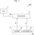
- FIG. 1 is a diagram illustrating a servo system 100 according to the embodiment.
- the servo system 100 includes a PLC 1, a servo driver 2, a motor 3, and an industrial network N1.
- the motor 3 includes a motor body 31, an encoder 32, and an output shaft 33.
- the PLC 1 and the servo driver 2 are connected to each other by the industrial network N1.
- the servo driver 2 and the motor body 31 are connected to each other by a power line 7.
- the servo driver 2 and the encoder 32 are connected to each other by an encoder cable 8.
- the PLC 1 outputs a command signal to the servo driver 2 via the industrial network N1.
- the PLC 1 functions as, for example, a monitoring device of the servo driver 2 by performing processing according to a prepared program.
- the industrial network N1 is, for example, a TCP/IP network.
- the servo driver 2 receives a command signal from the PLC 1 via the industrial network N1.
- the servo driver 2 receives a feedback signal from the encoder 32 of the corresponding motor 3 via the encoder cable 8.
- the servo driver 2 supplies a drive current to the motor body 31 of the motor 3 via the power line 7.
- a servo system that performs feedback control using a speed detector, a torque detector, a power generator, and the like are formed. These signals are used to servo control and drive the motor 3.
- the servo driver 2 is an example of a "control device".
- the motor 3 is, for example, a three-phase AC servo motor.
- the motor 3 includes the motor body 31 and the encoder 32.
- the motor body 31 receives a drive current from the servo driver 2 via the power line 7.
- the encoder 32 detects an operation of the motor body 31 by the servo driver 2 and generates a feedback signal indicating the detected operation.
- the feedback signal is output to the servo driver 2 via the encoder cable 8.
- the feedback signal includes information related to displacement of the output shaft 33, such as information relating to a rotational position (angle) of the output shaft 33 of the motor body 31, information relating to a rotational speed of the output shaft 33, and information relating to a rotation direction of the output shaft 33, for example.
- known incremental-type signal generation unit or absolute-type signal generation unit can be used as the configuration of the encoder 32.
- the motor 3 is an example of a "three-phase AC motor".
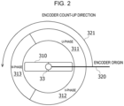
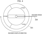
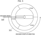
- FIGS. 2 to 5 are diagrams each schematically illustrating an arrangement order of a U-phase, a V-phase, and a W-phase and a count-up direction of the encoder 32when the motor 3 is viewed from the axial direction of the output shaft 33.
- an origin position when the encoder 32 counts the number of rotations of the encoder 32 is also illustrated.
- a U-phase coil 311, a V-phase coil 312, and a W-phase coil 313 are arranged so as to surround a rotor 310 to which the output shaft 33 is attached.
- the encoder 32 determines that the rotation direction is a positive direction when the output shaft 33 rotates in the direction of the output shaft 331.
- the encoder 32 counts an amount of rotation of the output shaft 33 with reference to an encoder origin 320.
- FIGS. 2 and 3 when FIGS. 2 and 3 are compared, the arrangement orders of the V-phase coil 312 and the W-phase coil 313 are reversed.
- FIGS. 2 and 4 When FIGS. 2 and 4 are compared, encoder count-up directions 321 are reversed.
- FIGS. 2 and 5 positions of the encoder origin 320 are different from each other.
- the arrangement order of the U-phase coil 311, the V-phase coil 312, and the W-phase coil 313, the position of the encoder origin 320, and the encoder count-up direction 321 may be different for each model of the motor 3.
- the arrangement order of the U-phase coil 311, the V-phase coil 312, and the W-phase coil 313, the position of the encoder origin 320, and the encoder count-up direction 321 are preset with respect to the servo driver 2.
- the back electromotive force generated by rotating the output shaft 33 by hand in a direction desired to be set as the positive direction by a user of the servo system 100 and the feedback signal from the encoder 32 information on the arrangement order of the U-phase coil 311, the V-phase coil 312, and the W-phase coil 313, the position of the encoder origin 320, and the encoder count-up direction 321 are acquired, and the acquired information is set in the servo driver 2.
- the direction desired to be set as the positive direction by the user is an example of a "desired direction".
- FIG. 6 is a view illustrating a state in which the output shaft 33 of the motor 3 is rotated by hand.
- the output shaft 33 is rotated in a counterclockwise direction when facing the output shaft 33.
- the back electromotive force generated by rotating the output shaft 33 is input to the servo driver 2 via the power line 7.
- the feedback signal from the encoder 32 that detects the rotation of the output shaft 33 is input to the servo driver 2 via the encoder cable 8.
- FIG. 7 is a diagram illustrating a schematic configuration of functional units included in the servo driver 2 according to the present embodiment.
- the servo driver 2 can be regarded as a computer including an arithmetic device and a storage device.
- the functional units illustrated in FIG. 7 are implemented by a predetermined program or the like being executed at the servo driver 2.
- the servo driver 2 includes a first reception unit 11, a second reception unit 12, an estimation unit 13, a setting unit 14, a control unit 15, and a storage unit 16, and may include functional units other than these units.
- the first reception unit 11 acquires a back electromotive force from the motor body 31 via the power line 7.
- the back electromotive force is generated.
- FIG. 8 is a diagram showing the back electromotive force generated by the output shaft 33 being rotated by hand.
- the vertical axis represents the back electromotive force
- the horizontal axis represents time.
- the first reception unit 11 causes the storage unit 16 to store a time-series change in the received back electromotive force generated in each of the U-phase coil 311, the V-phase coil 312, and the W-phase coil 313.
- the first reception unit 11 is an example of a "first acquisition unit”.
- the time-series change in the back electromotive force is an example of "information related to the back electromotive force".
- FIG. 9 is a diagram showing an electrical angular velocity by the output shaft 33 being rotated by hand.
- the vertical axis represents electrical angular velocity (degree/second), and the horizontal axis represents time (second).
- the encoder 32 outputs the feedback signal including information indicating the detected rotation direction and rotation speed of the output shaft 33 to the servo driver 2.
- the second reception unit 12 causes the storage unit 16 to store the time-series change in the rotation speed of the output shaft 33 indicated by the received feedback signal.
- the second reception unit 12 is an example of a "second acquisition unit”.
- the estimation unit 13 estimates the arrangement order of the U-phase coil 311, the V-phase coil 312, and the W-phase coil 313, an encoder offset for correcting a deviation between an electrical angle of the motor 3 and the origin of the encoder 32 (in other words, a deviation between a dq-axis of the servo driver 2 and a dq-axis of the motor 3), and a direction in which the output shaft 33 counts up the number of rotations based on the information stored in the storage unit 16 by the first reception unit 11 and the second reception unit 12.
- the estimation unit 13 is an example of a "control unit”.
- the encoder offset is an example of an "offset".
- the estimation unit 13 estimates the arrangement order of the U-phase coil 311, the V-phase coil 312, and the W-phase coil 313 based on, for example, the order in which the back electromotive force is generated.
- the estimation unit 13 estimates a count-up direction of the encoder 32 based on, for example, a positive or negative of the rotation speed of the output shaft 33 indicated by the feedback signal.
- FIG. 10 is a diagram schematically illustrating measurement of a voltage input via the power line 7 from the motor 3 whose output shaft 33 is rotated by hand.
- the servo driver 2 includes a voltmeter 21, and the voltage input from the motor 3 is measured by the voltmeter 21.
- the first acquisition unit 11 may measure a measurement line voltage by the voltmeter 21 instead of directly measuring the back electromotive force.
- the measurement line voltage include a voltage between the U-phase and the V-phase, a voltage between the W-phase and the V-phase, and a voltage between the U-phase and the W-phase.
- FIG. 11 is a diagram showing the time-series change in the measurement line voltage.
- the vertical axis represents voltage (V) and the horizontal axis represents time (second).
- V voltage
- second time
- the voltage between the W-phase and the V-phase and the voltage between the U-phase and the W-phase are shown.
- the measurement line voltage is an example of the "information related to the back electromotive force".
- the estimation unit 13 can estimate the arrangement order of the U-phase coil 311, the V-phase coil 312, and the W-phase coil 313 based on a positive or negative of the other measurement line voltages at a zero cross point of a certain measurement line voltage.
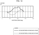
- FIGS. 12 and 13 are diagrams each showing a correspondence relationship between the measurement line voltage and the electrical angle recognized by the servo driver 2.
- the vertical axis represents voltage (V)
- the horizontal axis represents electrical angle (degree).
- FIG. 12 illustrates a case where the arrangement order of the U-phase coil 311, the V-phase coil 312, and the W-phase coil 313, preset in the servo driver 2 matches the arrangement order of the U-phase coil 311, the V-phase coil 312, and the W-phase coil 313 in the motor 3.
- FIG. 13 illustrates a case where the arrangement order of the U-phase coil 311, the V-phase coil 312, and the W-phase coil 313, preset in the servo driver 2 is deferent from the arrangement order of the U-phase coil 311, the V-phase coil 312, and the W-phase coil 313 in the motor 3.
- a correspondence relationship between the change in the measurement line voltage acquired by the first acquisition unit 11 and the electrical angle indicated by the feedback signal acquired by the second acquisition unit is stored in the storage unit 16.
- the correspondence relationship between the measurement line voltage and the electrical angle shown in FIGS. 12 and 13 is an example of a "first correspondence relationship".
- the estimation unit 13 estimates that the arrangement order of the U-phase coil 311, the V-phase coil 312, and the W-phase coil 313, preset matches the arrangement order of the U-phase coil 311, the V-phase coil 312, and the W-phase coil 313 arranged in the motor 3.
- the estimation unit 13 estimates that the U-phase coil 311, the V-phase coil 312, and the W-phase coil 313 are arranged in this order with respect to the direction in which the output shaft 33 is rotated by hand.
- the estimation unit 13 estimates that the arrangement order of the U-phase coil 311, the V-phase coil 312, and the W-phase coil 313, preset is reversed to the arrangement order of the U-phase coil 311, the V-phase coil 312, and the W-phase coil 313 arranged in the motor 3.
- the estimation unit 13 estimates that the U-phase coil 311, the W-phase coil 313, and the V-phase coil 312 are arranged in this order with respect to the direction in which the output shaft 33 is rotated by hand.
- the estimation unit 13 estimates that the arrangement order of the U-phase coil 311, the V-phase coil 312, and the W-phase coil 313, preset matches the arrangement order of the U-phase coil 311, the V-phase coil 312, and the W-phase coil 313, arranged in the motor 3.
- the estimation unit 13 estimates that the arrangement order of the U-phase coil 311, the V-phase coil 312, and the W-phase coil 313, preset matches the arrangement order of the U-phase coil 311, the V-phase coil 312, and the W-phase coil 313 arranged in the motor 3.
- the estimation unit 13 estimates the encoder offset.
- the estimation unit 13 estimates that the U-phase coil 311, the V-phase coil 312, and the W-phase coil 313 are arranged in this order with respect to the direction in which the output shaft 33 is rotated by hand.
- the zero cross point of the voltage between the U-phase and the W-phase in FIG. 12 is at the electrical angles of 60 degrees and 180 degrees.
- the voltage between the U-phase and the W-phase decreases at a point at which the electrical angle is 60 degrees.
- the voltage between the U-phase and the W-phase increases at a point at which the electrical angle is 180 degrees. That is, a rate of change in the voltage between the U-phase and the W-phase at the electrical angle of 180 degrees is positive.
- FIG. 14 is a diagram showing a correspondence relationship between a three-phase voltage measured from a neutral point and the electrical angle. It can be said that FIG. 14 shows a true value of the electrical angle.
- the correspondence relationship between the three-phase voltage and the electrical angle shown in FIG. 14 may be stored in advance in the storage unit 16 of the servo driver 2, for example.
- FIG. 14 it can be understood that the voltage of the U-phase and the voltage of the W-phase are equal to each other when the electrical angle is 30 degrees and 210 degrees.
- FIG. 14 it can be understood that the voltage of the U-phase and the voltage of the W-phase are equal to each other when the electrical angle is 30 degrees and 210 degrees.
- the point at which the voltage of the U-phase and the voltage of the W-phase are equal to each other corresponds to, for example, a zero cross point of the voltage between the U-phase and the W-phase in FIG. 14 .
- the zero cross points of the voltage between the U-phase and the W-phase shown in FIG. 14 the voltage between the U-phase and the W-phase at the electrical angle of 60 degrees tends to decrease, and the voltage between the U-phase and the W-phase at the electrical angle of 180 degrees tends to increase.
- the correspondence relationship between the three-phase voltage and the electrical angle shown in FIG. 14 is an example of a "second correspondence relationship".
- the zero cross point at the electrical angle of 60 degrees corresponds to the electrical angle of 30 degrees in FIG. 14 .
- the zero cross point at the electrical angle of 180 degrees corresponds to the electrical angle of 210 degrees in FIG. 14 .
- the encoder offset to be set in the servo driver 2 can be calculated by subtracting the electrical angle assumed by the servo driver 2 from the true value of the electrical angle.
- the true value of the electrical angle is 210 degrees.
- the estimation unit 13 can calculate the electrical angle of 30 degrees as the encoder offset by subtracting the electrical angle of 180 degrees assumed by the servo driver 2 from 210 degrees which is the true value of the electrical angle.
- the setting unit 14 causes the servo driver 2 to store each piece of information related to the motor 3 estimated by the estimation unit 13 in the storage unit 16.
- the servo driver 2 can perform servo control of the motor 3 by using the information stored in the storage unit 16.
- the control unit 15 performs feedback control of the motor 3 according to the command signal from the PLC 1 by using each piece of information related to the motor 3 stored in the storage unit 16 by the setting unit 14.
- the control unit 15 is an example of a "control unit”.
- the storage unit 16 stores information acquired by the first reception unit 11 and the second reception unit 12 and information related to processing performed by the first reception unit 11, the second reception unit 12, the estimation unit 13, the setting unit 14, and the control unit 15.
- the storage unit 16 is, for example, an EEPROM.
- the storage unit 16 is an example of a "storage unit".
- FIG. 15 is a diagram illustrating an example of processing flow of processing of estimating the count-up direction of the encoder by the estimation unit 13.
- FIG. 15 an example of processing of estimating the count-up direction of the encoder by the estimation unit 13 will be described.
- the output shaft 33 of the motor 3 is rotated by hand toward a rotation direction desired to be set as the positive direction by the user of the servo system 100.
- the second reception unit 12 receives the feedback signal from the encoder 32.
- the estimation unit 13 determines whether a count value of the encoder indicating the rotation direction of the output shaft 33 indicates the positive direction based on the feedback signal received by the second reception unit 12. If the positive direction is indicated (YES in S2), then the count-up direction is correctly set in the servo driver 2, and thus the processing is ended. If the direction is not the positive direction (if the direction is negative) (NO in S2), then the processing proceeds to S3.
- the count value of the encoder indicating the rotation direction of the output shaft 33 is an example of a "parameter indicating the rotation direction of the output shaft".
- the estimation unit 13 detects that the count-up direction stored in advance in the storage unit 16 of the servo driver 2 is reversed to the count-up direction of the encoder 32.
- the setting unit 14 reverses the count-up direction stored in advance in the storage unit 16 and causes the storage unit 16 to store thereof.
- the setting unit 14 may cause the storage unit 16 to store information indicating that the count-up direction is reverse to the direction stored in advance in the storage unit 16. For example, when the information indicating the reverse direction is stored in the storage unit 16, the control unit 15 may count the rotation amount of the output shaft 33 on the assumption that the rotation amount of the output shaft 33 has increased by a decreased amount in the rotation amount of the output shaft 33 indicated by the feedback signal from the encoder 32.
- the information indicating the reverse direction is an example of "first information".
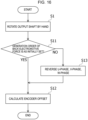
- FIG. 16 is a diagram illustrating an example of processing flow of processing of estimating the offset of the encoder by the estimation unit 13.
- the same processing as that in FIG. 15 is denoted by the same reference sign, and a description thereof will be omitted.
- FIG. 16 an example of processing of estimating the offset of the encoder by the estimation unit 13 will be described.
- the first reception unit 11 receives the back electromotive forces from the motor 3.
- the estimation unit 13 estimates the arrangement order of the U-phase coil 311, the V-phase coil 312, and the W-phase coil 313 based on a positive or negative of the other measurement line voltage at the zero cross point of a certain measurement line voltage. If the estimated arrangement order matches the arrangement order preset in the servo driver 2 (YES in S11), the arrangement order of the U-phase, the V-phase, and the W-phase is correctly set in the servo driver 2, and then the processing proceeds to S12. If the estimated arrangement order does not match the arrangement order preset in the servo driver 2 (NO in S11), then the processing proceeds to S13.
- the estimation unit 13 calculates the encoder offset of the encoder 32 for correcting the deviation between the dq-axis of the servo driver 2 and the dq-axis of the motor 3.
- the setting unit 14 causes the storage unit 16 to store the calculated encoder offset.
- the setting unit 14 changes the order of the U-phase, the V-phase, and the W-phase stored in advance in the storage unit 16 of the servo driver 2 to the reverse order and causes the storage unit 16 to store the reverse order. That is, the setting unit 14 causes the storage unit 16 to store the order of the U-phase, the V-phase, and the W-phase according to the generation order of the back electromotive forces acquired in S11.
- information related to the motor 3 is acquired and stored in the storage unit 16 by rotating the output shaft 33 by hand in the desired direction of the user.
- the control unit 15 can control the motor 3 by using the information stored in the storage unit 16. That is, according to the present embodiment, the information related to the motor 3 which is the three-phase AC motor can be stored in the storage unit 16 by a simple method.
- the arrangement order of the U-phase coil 311, the V-phase coil 312, and the W-phase coil 313 is estimated based on the time-series change in the back electromotive forces generated by rotating the output shaft 33 by hand, and the estimated arrangement order is stored in the storage unit 16.
- the control unit 15 can supply currents to the U-phase coil 311, the V-phase coil 312, and the W-phase coil 313 and can drive the motor 3 by referencing to the arrangement order stored in the storage unit 16.
- the estimation unit 13 determines whether the count value of the encoder indicating the rotation amount of the output shaft 33 has increased based on the feedback signal when the output shaft 33 is rotated by hand. When the count value decreases, the estimation unit 13 detects that the count-up direction stored in advance in the storage unit 16 is reversed to the count-up direction of the encoder 32. Then, the setting unit 14 can match the desired direction with the count-up direction by reversing the count-up direction stored in advance in the storage unit 16. The setting unit 14, the setting unit 14 may cause the storage unit 16 to store the information indicating that the count-up direction is reversed to the direction stored in advance in the storage unit 16.
- the encoder offset for correcting the deviation between the electrical angle of the motor 3 and the origin of the encoder 32 is estimated by the estimation unit 13.
- the servo driver 2 can correct the deviation to control the motor 3.
- the electrical angle of 0 degrees is present, for example, at a position of 10000 pulses, the servo driver 2 may set 10000 pulses as the encoder offset and control the motor 3.
- the arrangement order of the U-phase coil 311, the V-phase coil 312, and the W-phase coil 313 is estimated using the measurement line voltage generated when the output shaft 33 is rotated by hand.
- the arrangement order of the U-phase coil 311, the V-phase coil 312, and the W-phase coil 313 can also be estimated using, for example, a current generated when the output shaft 33 is rotated by hand.
- processing of estimating the arrangement order of the U-phase coil 311, the V-phase coil 312, and the W-phase coil 313 by using the current generated when the output shaft 33 is rotated by hand will be described.
- FIG. 17 is a diagram schematically illustrating measurement of a current input via the power line 7 from the motor 3 whose output shaft 33 is rotated by hand.
- the servo driver 2 includes ammeters 22a, 22b, and 22c.
- a current value of the U-phase, a current value of the V-phase, and a current value of the W-phase are measured by the voltmeter 22a, the ammeter 22b, and the ammeter 22c, respectively.
- the current value is measured, for example, the U-phase, the V-phase, and the W-phase are shortcircuited in the servo driver 2.
- FIG. 18 is a diagram showing current values generated when the electrical angular velocity illustrated in FIG. 9 is supplied.
- the vertical axis represents current (A) and the horizontal axis represents time (second).
- the arrangement order of the U-phase coil 311, the V-phase coil 312, and the W-phase coil 313 in the motor 3 and the encoder offset to be set in the servo driver 2 can also be estimated using the current similarly to the method described using the voltage with reference to FIGS. 12 and 13 .
- the estimation unit 13 can estimate the arrangement order of the U-phase coil 311, the V-phase coil 312, and the W-phase coil 313 of the motor 3 based on a positive or negative of the current value of the V-phase at the zero cross point of the current of the U-phase.
- the estimation unit 13 can estimate the encoder offset based on, for example, a positive or negative of the rate of change in the current value of the U-phase at the zero cross point of the current of the U-phase. As an example, the estimation unit 13 can estimate that when the rate of change in the current value of the U-phase at the zero cross point of the current of the U-phase is positive, the direction of the q-axis current is 270 degrees and the electrical angle (angle of the d-axis) is 180 degrees.
- a control device (2) that controls a three-phase AC motor (3) including an encoder (32) that outputs a feedback signal indicating a rotation state of an output shaft (33), a U-phase coil (311), a V-phase coil (312), and a W-phase coil (313), the control device (2) including:
Landscapes
- Engineering & Computer Science (AREA)
- Power Engineering (AREA)
- Control Of Electric Motors In General (AREA)
- Control Of Ac Motors In General (AREA)
Abstract
Description
- The present invention relates to a control device.
- A motor including a servo driver that performs servo control by receiving a feedback signal from a motor and an encoder that detects a rotation state of a motor shaft is used (for example, refer to
Patent Documents 1 to 3). -
- Patent Document 1:
JP 2018-061327 A - Patent Document 2:
JP 2018-191422 A - Patent Document 3:
JP 2010-057302 A - In a servo system, information related to motor control such as an arrangement order of three-phase coils disposed in an associated three-phase AC motor and information related to an encoder included in the three-phase AC motor is set in a servo driver. Then, the servo driver controls the three-phase AC motor by using the set information related to the motor control. Since the information related to the motor control is different for each model of the three-phase AC motor, it takes time to confirm the information related to the motor control by a manual or the like before the operation of the servo system and set the information in the servo driver.
- An object of one aspect of the disclosed technique is to provide a control device that can acquire information related to control of the three-phase AC motor by a simpler method.
- One aspect of the disclosed technique is exemplified by the following control device. The present control device is a control device that controls a three-phase AC motor including an encoder that outputs a feedback signal indicating a rotation state of an output shaft, a U-phase coil, a V-phase coil, and a W-phase coil. The control device includes a first acquisition unit configured to acquire information related to back electromotive forces generated in the U-phase coil, the V-phase coil, and the W-phase coil due to the output shaft being rotating in a desired direction by an external force, a second acquisition unit configured to acquire, from the encoder, the feedback signal including information related to rotation of the output shaft rotated by the external force, and a control unit configured to estimate information related to control of the three-phase AC motor based on the information related to the back electromotive forces and the feedback signal and control the three-phase AC motor by using the estimated information related to control of the three-phase AC motor.
- When the output shaft is rotated in a desired direction by an external force, back electromotive forces are generated in the U-phase coil, the V-phase coil and the W-phase coil, and a current caused by each of the back electromotive forces flows to the control device. When the output shaft is rotated in the desired direction by the external force, a feedback signal indicating the rotation is output to the control device. The control device estimates information related to control of the three-phase AC motor based on information related to the back electromotive forces generated in the U-phase coil, the V-phase coil, and the W-phase coil and the feedback signal, uses the estimated information related to control of the three-phase AC motor, and thus can control the three-phase AC motor. That is, the control device can set information related to the motor by a simple operation of rotating the output shaft in the desired direction by an external force.
- The control device may have the following feature. The control unit estimates the arrangement order of the U-phase coil, the V-phase coil, and the W-phase coil based on the information related to the back electromotive forces, and controls the three-phase AC motor by using the estimated arrangement order of the U-phase coil, the V-phase coil, and the W-phase coil. The control device having such a feature can supply currents to the U-phase coil, the V-phase coil, and the W-phase coil and can drive the three-phase AC motor by using the estimated arrangement order.
- The control device may have the following feature. The information related to the back electromotive forces includes a first correspondence relationship between a voltage and an electrical angle between any two phases of a U-phase, a V-phase, and a W-phase. The control unit acquires a positive or negative of a rate of a change in the voltage between the two phases when the voltage between the two phases is 0 in the first correspondence relationship and a first electrical angle when the voltage between the two phases is 0, determines an offset for correcting a deviation between an electrical angle of the three-phase AC motor and an origin of the encoder based on a second correspondence relationship between a voltage and an electrical angle of each of the U-phase, the V-phase, and the W-phase stored in advance in the storage unit, the positive or negative of the rate of the change in the voltage and the first electrical angle acquired, and the estimated arrangement order of the U-phase coil, the V-phase coil, and the W-phase coil, and controls the three-phase AC motor by also using the determined offset. With such a feature, even when a deviation occurs between the origin of the encoder and 0 degrees of the electrical angle of the motor, the control device can correct the deviation and control the three-phase AC motor. The offset may be determined using a current value instead of the voltage.
- The control device may have the following feature. The information related to control of the three-phase AC motor includes a parameter indicating a rotational direction of the output shaft notified through the feedback signal. The control unit controls the three-phase AC motor by causing the storage unit to store first information when the output shaft is rotated in the desired direction, and the parameter indicating the rotational direction of the output shaft notified through the feedback signal indicates a negative direction, and determining that the output shaft is rotated in a direction opposite to the rotational direction of the output shaft notified through the feedback signal when the first information is stored in the storage unit. With such a feature, the control device can control the three-phase AC motor with a desired direction as a positive direction.
- According to the disclosed technique, information related to control of the three-phase AC motor can be acquired by a simpler method.
-
-
FIG. 1 is a diagram illustrating a servo system according to an embodiment.FIG. 2 is a first diagram schematically illustrating an arrangement order of a U-phase, a V-phase, and a W-phase and a count-up direction of an encoder when amotor 3 is viewed from an axial direction of an output shaft. -
FIG. 3 is a second diagram schematically illustrating the arrangement order of the U-phase, the V-phase, and the W-phase and the count-up direction of the encoder when themotor 3 is viewed from the axial direction of the output shaft. -
FIG. 4 is a third diagram schematically illustrating the arrangement order of the U-phase, the V-phase, and the W-phase and the count-up direction of the encoder when themotor 3 is viewed from the axial direction of the output shaft. -
FIG. 5 is a fourth diagram schematically illustrating the arrangement order of the U-phase, the V-phase, and the W-phase and the count-up direction of the encoder when themotor 3 is viewed from the axial direction of the output shaft. -
FIG. 6 is a diagram illustrating a state in which the output shaft of the motor is rotated by hand. -
FIG. 7 is a diagram illustrating a schematic configuration of functional units included in a servo driver according to the present embodiment. -
FIG. 8 is a diagram showing a back electromotive force generated by the output shaft being rotated by hand. -
FIG. 9 is a diagram showing an electrical angular velocity by the output shaft being rotated by hand. -
FIG. 10 is a diagram schematically illustrating measurement of a voltage input via a power line from the motor whose output shaft is rotated by hand. -
FIG. 11 is a diagram showing a time-series change in a measurement line voltage. -
FIG. 12 is a first diagram showing a correspondence relationship between the measurement line voltage and an electrical angle recognized by aservo driver 2. -
FIG. 13 is a second diagram showing the correspondence relationship between the measurement line voltage and the electrical angle recognized by theservo driver 2. -
FIG. 14 is a diagram showing a correspondence relationship between a three-phase voltage measured from a neutral point and an electrical angle. -
FIG. 15 is a diagram illustrating an example of processing flow of processing of estimating a count-up direction of an encoder by an estimation unit. -
FIG. 16 is a diagram illustrating an example of processing flow of processing of estimating an offset of the encoder by the estimation unit. -
FIG. 17 is a diagram schematically illustrating measurement of a current input via a power line from a motor whose output shaft is rotated by hand. -
FIG. 18 is a diagram showing current values generated when the electrical angular velocity illustrated inFIG. 9 is supplied. - An embodiment will be described below with reference to the drawings.
FIG. 1 is a diagram illustrating aservo system 100 according to the embodiment. Theservo system 100 includes aPLC 1, aservo driver 2, amotor 3, and an industrial network N1. Themotor 3 includes amotor body 31, anencoder 32, and anoutput shaft 33. ThePLC 1 and theservo driver 2 are connected to each other by the industrial network N1. Theservo driver 2 and themotor body 31 are connected to each other by apower line 7. Theservo driver 2 and theencoder 32 are connected to each other by anencoder cable 8. - The
PLC 1 outputs a command signal to theservo driver 2 via the industrial network N1. ThePLC 1 functions as, for example, a monitoring device of theservo driver 2 by performing processing according to a prepared program. The industrial network N1 is, for example, a TCP/IP network. - The
servo driver 2 receives a command signal from thePLC 1 via the industrial network N1. Theservo driver 2 receives a feedback signal from theencoder 32 of thecorresponding motor 3 via theencoder cable 8. Theservo driver 2 supplies a drive current to themotor body 31 of themotor 3 via thepower line 7. In theservo driver 2, a servo system that performs feedback control using a speed detector, a torque detector, a power generator, and the like are formed. These signals are used to servo control and drive themotor 3. Theservo driver 2 is an example of a "control device". - The
motor 3 is, for example, a three-phase AC servo motor. Themotor 3 includes themotor body 31 and theencoder 32. Themotor body 31 receives a drive current from theservo driver 2 via thepower line 7. Theencoder 32 detects an operation of themotor body 31 by theservo driver 2 and generates a feedback signal indicating the detected operation. The feedback signal is output to theservo driver 2 via theencoder cable 8. The feedback signal includes information related to displacement of theoutput shaft 33, such as information relating to a rotational position (angle) of theoutput shaft 33 of themotor body 31, information relating to a rotational speed of theoutput shaft 33, and information relating to a rotation direction of theoutput shaft 33, for example. For example, known incremental-type signal generation unit or absolute-type signal generation unit can be used as the configuration of theencoder 32. Themotor 3 is an example of a "three-phase AC motor". -
FIGS. 2 to 5 are diagrams each schematically illustrating an arrangement order of a U-phase, a V-phase, and a W-phase and a count-up direction of the encoder 32when themotor 3 is viewed from the axial direction of theoutput shaft 33. InFIGS. 2 to 5 , an origin position when the encoder 32 counts the number of rotations of theencoder 32 is also illustrated. - In the
motor 3, aU-phase coil 311, a V-phase coil 312, and a W-phase coil 313 are arranged so as to surround arotor 310 to which theoutput shaft 33 is attached. Theencoder 32 determines that the rotation direction is a positive direction when theoutput shaft 33 rotates in the direction of the output shaft 331. The encoder 32 counts an amount of rotation of theoutput shaft 33 with reference to anencoder origin 320. - Here, when
FIGS. 2 and3 are compared, the arrangement orders of the V-phase coil 312 and the W-phase coil 313 are reversed. WhenFIGS. 2 and4 are compared, encoder count-updirections 321 are reversed. WhenFIGS. 2 and5 are compared, positions of theencoder origin 320 are different from each other. As described above, in themotor 3, the arrangement order of theU-phase coil 311, the V-phase coil 312, and the W-phase coil 313, the position of theencoder origin 320, and the encoder count-updirection 321 may be different for each model of themotor 3. Thus, in order to appropriately perform servo control of themotor 3 by theservo driver 2, the arrangement order of theU-phase coil 311, the V-phase coil 312, and the W-phase coil 313, the position of theencoder origin 320, and the encoder count-updirection 321 are preset with respect to theservo driver 2. - In the present embodiment, by using the back electromotive force generated by rotating the
output shaft 33 by hand in a direction desired to be set as the positive direction by a user of theservo system 100 and the feedback signal from theencoder 32, information on the arrangement order of theU-phase coil 311, the V-phase coil 312, and the W-phase coil 313, the position of theencoder origin 320, and the encoder count-updirection 321 are acquired, and the acquired information is set in theservo driver 2. The direction desired to be set as the positive direction by the user is an example of a "desired direction". -
FIG. 6 is a view illustrating a state in which theoutput shaft 33 of themotor 3 is rotated by hand. In the example ofFIG. 6 , theoutput shaft 33 is rotated in a counterclockwise direction when facing theoutput shaft 33. The back electromotive force generated by rotating theoutput shaft 33 is input to theservo driver 2 via thepower line 7. The feedback signal from theencoder 32 that detects the rotation of theoutput shaft 33 is input to theservo driver 2 via theencoder cable 8. -
FIG. 7 is a diagram illustrating a schematic configuration of functional units included in theservo driver 2 according to the present embodiment. Theservo driver 2 can be regarded as a computer including an arithmetic device and a storage device. The functional units illustrated inFIG. 7 are implemented by a predetermined program or the like being executed at theservo driver 2. Theservo driver 2 includes afirst reception unit 11, asecond reception unit 12, anestimation unit 13, asetting unit 14, acontrol unit 15, and astorage unit 16, and may include functional units other than these units. - The
first reception unit 11 acquires a back electromotive force from themotor body 31 via thepower line 7. As described with reference toFIG. 6 , when theoutput shaft 33 is rotated by hand, the back electromotive force is generated.FIG. 8 is a diagram showing the back electromotive force generated by theoutput shaft 33 being rotated by hand. InFIG. 8 , the vertical axis represents the back electromotive force, and the horizontal axis represents time. When theoutput shaft 33 is rotated by hand, the back electromotive force corresponding to the rotational speed of theoutput shaft 33 is generated in theU-phase coil 311, the V-phase coil 312, and the W-phase coil 313. Thefirst reception unit 11 causes thestorage unit 16 to store a time-series change in the received back electromotive force generated in each of theU-phase coil 311, the V-phase coil 312, and the W-phase coil 313. Thefirst reception unit 11 is an example of a "first acquisition unit". The time-series change in the back electromotive force is an example of "information related to the back electromotive force". - Referring back to
FIG. 7 , thesecond reception unit 12 acquires the feedback signal from theencoder 32 via theencoder cable 8.FIG. 9 is a diagram showing an electrical angular velocity by theoutput shaft 33 being rotated by hand. InFIG. 9 , the vertical axis represents electrical angular velocity (degree/second), and the horizontal axis represents time (second). When theoutput shaft 33 is rotated by hand, the rotation direction and the rotation speed of theoutput shaft 33 are detected by theencoder 32. Theencoder 32 outputs the feedback signal including information indicating the detected rotation direction and rotation speed of theoutput shaft 33 to theservo driver 2. Thesecond reception unit 12 causes thestorage unit 16 to store the time-series change in the rotation speed of theoutput shaft 33 indicated by the received feedback signal. Thesecond reception unit 12 is an example of a "second acquisition unit". - Referring back to
FIG. 7 , theestimation unit 13 estimates the arrangement order of theU-phase coil 311, the V-phase coil 312, and the W-phase coil 313, an encoder offset for correcting a deviation between an electrical angle of themotor 3 and the origin of the encoder 32 (in other words, a deviation between a dq-axis of theservo driver 2 and a dq-axis of the motor 3), and a direction in which theoutput shaft 33 counts up the number of rotations based on the information stored in thestorage unit 16 by thefirst reception unit 11 and thesecond reception unit 12. Theestimation unit 13 is an example of a "control unit". The encoder offset is an example of an "offset". - The
estimation unit 13 estimates the arrangement order of theU-phase coil 311, the V-phase coil 312, and the W-phase coil 313 based on, for example, the order in which the back electromotive force is generated. Theestimation unit 13 estimates a count-up direction of theencoder 32 based on, for example, a positive or negative of the rotation speed of theoutput shaft 33 indicated by the feedback signal. - An example of processing of estimating the arrangement order of the
U-phase coil 311, the V-phase coil 312, and the W-phase coil 313 by using the back electromotive forces will be described below.FIG. 10 is a diagram schematically illustrating measurement of a voltage input via thepower line 7 from themotor 3 whoseoutput shaft 33 is rotated by hand. Theservo driver 2 includes avoltmeter 21, and the voltage input from themotor 3 is measured by thevoltmeter 21. The following equation (1) is established, where ω is an electrical angular velocity, Ld and Lq are two phase inductances, R is a phase resistance, Ke is an induced voltage constant, id is a d-axis current, iq is a q-axis current, and p is a differential operator.
[Equation 1]
- Since the current state is a servo-off state, id = 0 and iq = 0, and thus the following equation (2) is established.
[Equation 2]
- When the electrical angular velocity illustrated in
FIG. 9 is supplied by theoutput shaft 33 being rotated by hand, the back electromotive force as illustrated inFIG. 8 is generated. Here, it is difficult to measure the back electromotive force by thevoltmeter 21. Thus, in the present embodiment, thefirst acquisition unit 11 may measure a measurement line voltage by thevoltmeter 21 instead of directly measuring the back electromotive force. Examples of the measurement line voltage include a voltage between the U-phase and the V-phase, a voltage between the W-phase and the V-phase, and a voltage between the U-phase and the W-phase.FIG. 11 is a diagram showing the time-series change in the measurement line voltage. InFIG. 11 , the vertical axis represents voltage (V) and the horizontal axis represents time (second). InFIG. 11 , the voltage between the W-phase and the V-phase and the voltage between the U-phase and the W-phase are shown. The measurement line voltage is an example of the "information related to the back electromotive force". - The
estimation unit 13 can estimate the arrangement order of theU-phase coil 311, the V-phase coil 312, and the W-phase coil 313 based on a positive or negative of the other measurement line voltages at a zero cross point of a certain measurement line voltage.FIGS. 12 and13 are diagrams each showing a correspondence relationship between the measurement line voltage and the electrical angle recognized by theservo driver 2. InFIGS. 12 and13 , the vertical axis represents voltage (V), and the horizontal axis represents electrical angle (degree).FIG. 12 illustrates a case where the arrangement order of theU-phase coil 311, the V-phase coil 312, and the W-phase coil 313, preset in theservo driver 2 matches the arrangement order of theU-phase coil 311, the V-phase coil 312, and the W-phase coil 313 in themotor 3.FIG. 13 illustrates a case where the arrangement order of theU-phase coil 311, the V-phase coil 312, and the W-phase coil 313, preset in theservo driver 2 is deferent from the arrangement order of theU-phase coil 311, the V-phase coil 312, and the W-phase coil 313 in themotor 3. - In the
servo driver 2, for example, a correspondence relationship between the change in the measurement line voltage acquired by thefirst acquisition unit 11 and the electrical angle indicated by the feedback signal acquired by the second acquisition unit is stored in thestorage unit 16. The correspondence relationship between the measurement line voltage and the electrical angle shown inFIGS. 12 and13 is an example of a "first correspondence relationship". - In
FIG. 12 , the voltage between the U-phase and the W-phase is 0 V at the electrical angle of 180 degrees. The voltage between the W-phase and the U-phase at the electrical angle of 180 degrees is positive. Thus, theestimation unit 13 estimates that the arrangement order of theU-phase coil 311, the V-phase coil 312, and the W-phase coil 313, preset matches the arrangement order of theU-phase coil 311, the V-phase coil 312, and the W-phase coil 313 arranged in themotor 3. Here, theestimation unit 13 estimates that theU-phase coil 311, the V-phase coil 312, and the W-phase coil 313 are arranged in this order with respect to the direction in which theoutput shaft 33 is rotated by hand. - In
FIG. 13 , the voltage between the U-phase and the W-phase is 0 V at the electrical angle of 180 degrees. The voltage between the W-phase and the U-phase at the electrical angle of 180 degrees is negative. Thus, theestimation unit 13 estimates that the arrangement order of theU-phase coil 311, the V-phase coil 312, and the W-phase coil 313, preset is reversed to the arrangement order of theU-phase coil 311, the V-phase coil 312, and the W-phase coil 313 arranged in themotor 3. Here, theestimation unit 13 estimates that theU-phase coil 311, the W-phase coil 313, and the V-phase coil 312 are arranged in this order with respect to the direction in which theoutput shaft 33 is rotated by hand. - Thus, when a certain measurement line voltage is 0 and the other measurement line voltage is positive, the
estimation unit 13 estimates that the arrangement order of theU-phase coil 311, the V-phase coil 312, and the W-phase coil 313, preset matches the arrangement order of theU-phase coil 311, the V-phase coil 312, and the W-phase coil 313, arranged in themotor 3. When a certain measurement line voltage is 0 and the other measurement line voltage is negative, theestimation unit 13 estimates that the arrangement order of theU-phase coil 311, the V-phase coil 312, and the W-phase coil 313, preset matches the arrangement order of theU-phase coil 311, the V-phase coil 312, and the W-phase coil 313 arranged in themotor 3. - Subsequently, the
estimation unit 13 estimates the encoder offset. Here, it is assumed that theestimation unit 13 estimates that theU-phase coil 311, the V-phase coil 312, and the W-phase coil 313 are arranged in this order with respect to the direction in which theoutput shaft 33 is rotated by hand. The zero cross point of the voltage between the U-phase and the W-phase inFIG. 12 is at the electrical angles of 60 degrees and 180 degrees. InFIG. 12 , the voltage between the U-phase and the W-phase decreases at a point at which the electrical angle is 60 degrees. In addition, inFIG. 12 , the voltage between the U-phase and the W-phase increases at a point at which the electrical angle is 180 degrees. That is, a rate of change in the voltage between the U-phase and the W-phase at the electrical angle of 180 degrees is positive. -
FIG. 14 is a diagram showing a correspondence relationship between a three-phase voltage measured from a neutral point and the electrical angle. It can be said thatFIG. 14 shows a true value of the electrical angle. The correspondence relationship between the three-phase voltage and the electrical angle shown inFIG. 14 may be stored in advance in thestorage unit 16 of theservo driver 2, for example. InFIG. 14 , it can be understood that the voltage of the U-phase and the voltage of the W-phase are equal to each other when the electrical angle is 30 degrees and 210 degrees. InFIG. 14 , at an electrical angle of 30 degrees, the voltage between the U-phase and the W-phase tends to decrease (the rate of change is negative), and at an electrical angle of 180 degrees, the voltage between the U-phase and the W-phase tends to increase (the rate of change is positive). - The point at which the voltage of the U-phase and the voltage of the W-phase are equal to each other corresponds to, for example, a zero cross point of the voltage between the U-phase and the W-phase in
FIG. 14 . Among the zero cross points of the voltage between the U-phase and the W-phase shown inFIG. 14 , the voltage between the U-phase and the W-phase at the electrical angle of 60 degrees tends to decrease, and the voltage between the U-phase and the W-phase at the electrical angle of 180 degrees tends to increase. The correspondence relationship between the three-phase voltage and the electrical angle shown inFIG. 14 is an example of a "second correspondence relationship". - That is, it can be understood that, among the zero cross points of the voltage between the U-phase and the W-phase shown in
FIG. 12 , the zero cross point at the electrical angle of 60 degrees corresponds to the electrical angle of 30 degrees inFIG. 14 . Further, it can be understood that among the zero cross points of the voltage between the U-phase and the W-phase shown inFIG. 12 , the zero cross point at the electrical angle of 180 degrees corresponds to the electrical angle of 210 degrees inFIG. 14 . - Here, the encoder offset to be set in the
servo driver 2 can be calculated by subtracting the electrical angle assumed by theservo driver 2 from the true value of the electrical angle. In the present embodiment, for example, at a point at which theservo driver 2 assumes that the electrical angle is 180 degrees, the true value of the electrical angle is 210 degrees. Thus, theestimation unit 13 can calculate the electrical angle of 30 degrees as the encoder offset by subtracting the electrical angle of 180 degrees assumed by theservo driver 2 from 210 degrees which is the true value of the electrical angle. - The setting
unit 14 causes theservo driver 2 to store each piece of information related to themotor 3 estimated by theestimation unit 13 in thestorage unit 16. When the information related to themotor 3 is stored in thestorage unit 16, theservo driver 2 can perform servo control of themotor 3 by using the information stored in thestorage unit 16. - The
control unit 15 performs feedback control of themotor 3 according to the command signal from thePLC 1 by using each piece of information related to themotor 3 stored in thestorage unit 16 by the settingunit 14. Thecontrol unit 15 is an example of a "control unit". - The
storage unit 16 stores information acquired by thefirst reception unit 11 and thesecond reception unit 12 and information related to processing performed by thefirst reception unit 11, thesecond reception unit 12, theestimation unit 13, the settingunit 14, and thecontrol unit 15. Thestorage unit 16 is, for example, an EEPROM. Thestorage unit 16 is an example of a "storage unit". -
FIG. 15 is a diagram illustrating an example of processing flow of processing of estimating the count-up direction of the encoder by theestimation unit 13. Hereinafter, with reference toFIG. 15 , an example of processing of estimating the count-up direction of the encoder by theestimation unit 13 will be described. - In S1, the
output shaft 33 of themotor 3 is rotated by hand toward a rotation direction desired to be set as the positive direction by the user of theservo system 100. In S2, thesecond reception unit 12 receives the feedback signal from theencoder 32. Theestimation unit 13 determines whether a count value of the encoder indicating the rotation direction of theoutput shaft 33 indicates the positive direction based on the feedback signal received by thesecond reception unit 12. If the positive direction is indicated (YES in S2), then the count-up direction is correctly set in theservo driver 2, and thus the processing is ended. If the direction is not the positive direction (if the direction is negative) (NO in S2), then the processing proceeds to S3. The count value of the encoder indicating the rotation direction of theoutput shaft 33 is an example of a "parameter indicating the rotation direction of the output shaft". - In S3, the
estimation unit 13 detects that the count-up direction stored in advance in thestorage unit 16 of theservo driver 2 is reversed to the count-up direction of theencoder 32. The settingunit 14 reverses the count-up direction stored in advance in thestorage unit 16 and causes thestorage unit 16 to store thereof. The settingunit 14 may cause thestorage unit 16 to store information indicating that the count-up direction is reverse to the direction stored in advance in thestorage unit 16. For example, when the information indicating the reverse direction is stored in thestorage unit 16, thecontrol unit 15 may count the rotation amount of theoutput shaft 33 on the assumption that the rotation amount of theoutput shaft 33 has increased by a decreased amount in the rotation amount of theoutput shaft 33 indicated by the feedback signal from theencoder 32. The information indicating the reverse direction is an example of "first information". -
FIG. 16 is a diagram illustrating an example of processing flow of processing of estimating the offset of the encoder by theestimation unit 13. InFIG. 16 , the same processing as that inFIG. 15 is denoted by the same reference sign, and a description thereof will be omitted. Hereinafter, with reference toFIG. 16 , an example of processing of estimating the offset of the encoder by theestimation unit 13 will be described. - In S11, the
first reception unit 11 receives the back electromotive forces from themotor 3. Theestimation unit 13 estimates the arrangement order of theU-phase coil 311, the V-phase coil 312, and the W-phase coil 313 based on a positive or negative of the other measurement line voltage at the zero cross point of a certain measurement line voltage. If the estimated arrangement order matches the arrangement order preset in the servo driver 2 (YES in S11), the arrangement order of the U-phase, the V-phase, and the W-phase is correctly set in theservo driver 2, and then the processing proceeds to S12. If the estimated arrangement order does not match the arrangement order preset in the servo driver 2 (NO in S11), then the processing proceeds to S13. - In S12, the
estimation unit 13 calculates the encoder offset of theencoder 32 for correcting the deviation between the dq-axis of theservo driver 2 and the dq-axis of themotor 3. The settingunit 14 causes thestorage unit 16 to store the calculated encoder offset. - In S13, the setting
unit 14 changes the order of the U-phase, the V-phase, and the W-phase stored in advance in thestorage unit 16 of theservo driver 2 to the reverse order and causes thestorage unit 16 to store the reverse order. That is, the settingunit 14 causes thestorage unit 16 to store the order of the U-phase, the V-phase, and the W-phase according to the generation order of the back electromotive forces acquired in S11. - In the present embodiment, information related to the
motor 3 is acquired and stored in thestorage unit 16 by rotating theoutput shaft 33 by hand in the desired direction of the user. Thecontrol unit 15 can control themotor 3 by using the information stored in thestorage unit 16. That is, according to the present embodiment, the information related to themotor 3 which is the three-phase AC motor can be stored in thestorage unit 16 by a simple method. - In the present embodiment, for example, the arrangement order of the
U-phase coil 311, the V-phase coil 312, and the W-phase coil 313 is estimated based on the time-series change in the back electromotive forces generated by rotating theoutput shaft 33 by hand, and the estimated arrangement order is stored in thestorage unit 16. Thecontrol unit 15 can supply currents to theU-phase coil 311, the V-phase coil 312, and the W-phase coil 313 and can drive themotor 3 by referencing to the arrangement order stored in thestorage unit 16. - In the present embodiment, the
estimation unit 13 determines whether the count value of the encoder indicating the rotation amount of theoutput shaft 33 has increased based on the feedback signal when theoutput shaft 33 is rotated by hand. When the count value decreases, theestimation unit 13 detects that the count-up direction stored in advance in thestorage unit 16 is reversed to the count-up direction of theencoder 32. Then, the settingunit 14 can match the desired direction with the count-up direction by reversing the count-up direction stored in advance in thestorage unit 16. The settingunit 14, the settingunit 14 may cause thestorage unit 16 to store the information indicating that the count-up direction is reversed to the direction stored in advance in thestorage unit 16. - In the present embodiment, the encoder offset for correcting the deviation between the electrical angle of the
motor 3 and the origin of theencoder 32 is estimated by theestimation unit 13. Thus, according to the present embodiment, even when a deviation occurs between the origin of theencoder motor 3, theservo driver 2 can correct the deviation to control themotor 3. When the electrical angle of 0 degrees is present, for example, at a position of 10000 pulses, theservo driver 2 may set 10000 pulses as the encoder offset and control themotor 3. - In the embodiment, the arrangement order of the
U-phase coil 311, the V-phase coil 312, and the W-phase coil 313 is estimated using the measurement line voltage generated when theoutput shaft 33 is rotated by hand. However, the arrangement order of theU-phase coil 311, the V-phase coil 312, and the W-phase coil 313 can also be estimated using, for example, a current generated when theoutput shaft 33 is rotated by hand. In a first modified example, processing of estimating the arrangement order of theU-phase coil 311, the V-phase coil 312, and the W-phase coil 313 by using the current generated when theoutput shaft 33 is rotated by hand will be described. -
FIG. 17 is a diagram schematically illustrating measurement of a current input via thepower line 7 from themotor 3 whoseoutput shaft 33 is rotated by hand. Theservo driver 2 includesammeters voltmeter 22a, theammeter 22b, and theammeter 22c, respectively. When the current value is measured, for example, the U-phase, the V-phase, and the W-phase are shortcircuited in theservo driver 2. - Here, it is assumed that the electrical angular velocity illustrated in
FIG. 9 is supplied by rotating theoutput shaft 33 by hand.FIG. 18 is a diagram showing current values generated when the electrical angular velocity illustrated inFIG. 9 is supplied. InFIG. 18 , the vertical axis represents current (A) and the horizontal axis represents time (second). - In the above equation (1), since Vd and Vq are 0, the following equation (3) is established.
[Equation 3]
- When the equation (3) is approximated and the differential term is regarded as 0, the following equation (4) can be obtained. Since ω2 is sufficiently small because the
output shaft 33 is rotated by hand, the term id can be ignored.
[Equation 4]
- The arrangement order of the
U-phase coil 311, the V-phase coil 312, and the W-phase coil 313 in themotor 3 and the encoder offset to be set in theservo driver 2 can also be estimated using the current similarly to the method described using the voltage with reference toFIGS. 12 and13 . For example, inFIG. 18 , theestimation unit 13 can estimate the arrangement order of theU-phase coil 311, the V-phase coil 312, and the W-phase coil 313 of themotor 3 based on a positive or negative of the current value of the V-phase at the zero cross point of the current of the U-phase. Theestimation unit 13 can estimate the encoder offset based on, for example, a positive or negative of the rate of change in the current value of the U-phase at the zero cross point of the current of the U-phase. As an example, theestimation unit 13 can estimate that when the rate of change in the current value of the U-phase at the zero cross point of the current of the U-phase is positive, the direction of the q-axis current is 270 degrees and the electrical angle (angle of the d-axis) is 180 degrees. - The above-described embodiment and modification can be combined.
- A control device (2) that controls a three-phase AC motor (3) including an encoder (32) that outputs a feedback signal indicating a rotation state of an output shaft (33), a U-phase coil (311), a V-phase coil (312), and a W-phase coil (313), the control device (2) including:
- a first acquisition unit (11) configured to acquire information related to back electromotive forces generated in the U-phase coil (311), the V-phase coil (312), and the W-phase coil (313) due to the output shaft (33) being rotated in a desired direction by an external force;
- a second acquisition unit (12) configured to acquire, from the encoder (32), the feedback signal including information related to rotation of the output shaft (33) rotated by the external force; and
- a control unit (13, 15) configured to estimate information related to control of the three-phase AC motor (3) based on the information related to the back electromotive forces and the feedback signal and to control the three-phase AC motor (3) by using the estimated information related to control of the three-phase AC motor (3).
-
- 1 PLC
- 2 Servo driver
- 3 Motor
- 7 Power line
- 8 Encoder cable
- 11 First reception unit
- 12 Second reception unit
- 13 Estimation unit
- 14 Setting unit
- 15 Control unit
- 16 Storage unit
- 21 Voltmeter
- 22a, 22b, 22c Ammeter
- 31 Motor body
- 32 Encoder
- 33 Output shaft
- 100 Servo system
- 310 Rotor
- 311 U-phase coil
- 312 V-phase coil
- 313 W-phase coil
- 320 Encoder origin
- 321 Encoder count-up direction
- 500 Arrow
Claims (5)
- A control device configured to control a three-phase AC motor including an encoder configured to output a feedback signal indicating a rotation state of an output shaft, a U-phase coil, a V-phase coil, and a W-phase coil, the control device comprising:a first acquisition unit configured to acquire information related to back electromotive forces generated in the U-phase coil, the V-phase coil, and the W-phase coil due to the output shaft being rotated in a desired direction by an external force;a second acquisition unit configured to acquire, from the encoder, the feedback signal including information related to rotation of the output shaft rotated by the external force; anda control unit configured to estimate information related to control of the three-phase AC motor based on the information related to the back electromotive forces and the feedback signal, and to control the three-phase AC motor by using the estimated information related to control of the three-phase AC motor.
- The control device according to claim 1, wherein
the control unit:estimates an arrangement order of the U-phase coil, the V-phase coil, and the W-phase coil based on the information related to the back electromotive forces; andcontrols the three-phase AC motor by using the estimated arrangement order of the U-phase coil, the V-phase coil, and the W-phase coil. - The control device according to claim 2, whereinthe information related to the back electromotive forces includes a first correspondence relationship between a voltage and an electrical angle between any two phases among a U-phase, a V-phase, and a W-phase, andthe control unit:acquires a positive or negative of a rate of a change in the voltage between the two phases when the voltage between the two phases is 0 in the first correspondence relationship, and a first electrical angle when the voltage between the two phases is 0;determines an offset configured to correct a deviation between an electrical angle of the three-phase AC motor and an origin of the encoder based on a second correspondence relationship between a voltage and an electrical angle of each of the U-phase, the V-phase, and the W-phase stored in advance in a storage unit, the positive or negative of the rate of the change in the voltage and the first electrical angle acquired, and the estimated arrangement order of the U-phase coil, the V-phase coil, and the W-phase coil; andcontrols the three-phase AC motor by also using the determined offset.
- The control device according to claim 2, whereinthe information related to the back electromotive forces includes a third correspondence relationship between a current value and an electrical angle between any two phases of a U-phase, a V-phase, and a W-phase, andthe control unit:acquires a positive or negative of a rate of a change in the current value when the current value is 0 in the third correspondence relationship, and a second electrical angle when the current value is 0;determines an offset configured to correct a deviation between an electrical angle of the three-phase AC motor and an origin of the encoder based on a fourth correspondence relationship between the current value and the electrical angle of each of the U-phase, the V-phase, and the W-phase stored in advance in a storage unit, the positive or negative of the rate of the change in the current value and the first electrical angle acquired, and the estimated arrangement order of the U-phase coil, the V-phase coil, and the W-phase coil; andcontrols the three-phase AC motor by also using the determined offset.
- The control device according to any one of claims 1 to 4, whereinthe information related to control of the three-phase AC motor includes a parameter indicating a rotational direction of the output shaft notified through the feedback signal, andthe control unit controls the three-phase AC motor:by causing the storage unit to store first information when the output shaft is rotated in the desired direction and the parameter indicating the rotational direction of the output shaft notified through the feedback signal indicates a negative direction, anddetermining that the output shaft is rotated in a direction opposite to the rotational direction of the output shaft notified through the feedback signal when the first information is stored in the storage unit.
Applications Claiming Priority (2)
| Application Number | Priority Date | Filing Date | Title |
|---|---|---|---|
| JP2022062017A JP2023152076A (en) | 2022-04-01 | 2022-04-01 | Control device |
| PCT/JP2023/008342 WO2023189241A1 (en) | 2022-04-01 | 2023-03-06 | Control device |
Publications (2)
| Publication Number | Publication Date |
|---|---|
| EP4482022A1 true EP4482022A1 (en) | 2024-12-25 |
| EP4482022A4 EP4482022A4 (en) | 2025-12-17 |
Family
ID=88201299
Family Applications (1)
| Application Number | Title | Priority Date | Filing Date |
|---|---|---|---|
| EP23779270.0A Pending EP4482022A4 (en) | 2022-04-01 | 2023-03-06 | CONTROL DEVICE |
Country Status (4)
| Country | Link |
|---|---|
| EP (1) | EP4482022A4 (en) |
| JP (1) | JP2023152076A (en) |
| CN (1) | CN118947057A (en) |
| WO (1) | WO2023189241A1 (en) |
Family Cites Families (15)
| Publication number | Priority date | Publication date | Assignee | Title |
|---|---|---|---|---|
| JP2002165480A (en) * | 2000-11-21 | 2002-06-07 | Sharp Corp | Control device for brushless motor and inverter washing machine having the same |
| JP2002354876A (en) * | 2001-05-21 | 2002-12-06 | Toyota Motor Corp | Apparatus and method for detecting deviation of sensor reference point, control apparatus and control method for electric motor, method for determining abnormality of electric motor, method for adjusting mounting position of sensor |
| US6640417B2 (en) * | 2001-12-13 | 2003-11-04 | Pitney Bowes Inc. | Method for determining correct phasing of a three-phase brushless DC motor |
| US7423396B2 (en) * | 2004-06-11 | 2008-09-09 | International Rectifier Corporation | Hall sensor alignment for BLDC motor |
| JP5253044B2 (en) | 2008-08-29 | 2013-07-31 | キヤノン株式会社 | Motor with encoder and positioning device |
| JP5282960B2 (en) * | 2009-03-31 | 2013-09-04 | アイシン・エィ・ダブリュ株式会社 | Drive device information management system and drive device manufacturing method |
| JP5974539B2 (en) * | 2012-02-28 | 2016-08-23 | 株式会社ジェイテクト | Inspection method and motor control device |
| JP6022951B2 (en) * | 2013-01-18 | 2016-11-09 | トヨタ自動車株式会社 | Electric power steering device |
| CN204008953U (en) * | 2014-04-24 | 2014-12-10 | 上海奥波电子有限公司 | A kind of detection system for motor stator winding |
| WO2017002257A1 (en) * | 2015-07-02 | 2017-01-05 | 富士機械製造株式会社 | Servomotor drive device |
| JP6725839B2 (en) | 2016-10-04 | 2020-07-22 | シンフォニアテクノロジー株式会社 | Motor controller |
| JP6772848B2 (en) * | 2017-01-13 | 2020-10-21 | 日本精工株式会社 | Motor control device, electric power steering device and vehicle |
| JP2018191422A (en) | 2017-05-01 | 2018-11-29 | キヤノン株式会社 | Motor controller and method for controlling the same |
| TWI683530B (en) * | 2018-05-25 | 2020-01-21 | 茂達電子股份有限公司 | Motor driving circuit and method thereof |
| JP2020096503A (en) * | 2018-12-04 | 2020-06-18 | アイシン精機株式会社 | Motor controller |
-
2022
- 2022-04-01 JP JP2022062017A patent/JP2023152076A/en active Pending
-
2023
- 2023-03-06 CN CN202380029985.8A patent/CN118947057A/en active Pending
- 2023-03-06 WO PCT/JP2023/008342 patent/WO2023189241A1/en not_active Ceased
- 2023-03-06 EP EP23779270.0A patent/EP4482022A4/en active Pending
Also Published As
| Publication number | Publication date |
|---|---|
| WO2023189241A1 (en) | 2023-10-05 |
| EP4482022A4 (en) | 2025-12-17 |
| JP2023152076A (en) | 2023-10-16 |
| CN118947057A (en) | 2024-11-12 |
Similar Documents
| Publication | Publication Date | Title |
|---|---|---|
| EP3007352B1 (en) | Device for detecting magnetic pole position of permanent magnet-type synchronous motor | |
| EP3185411B1 (en) | Method and apparatus for motor lock or stall detection | |
| EP0944164B1 (en) | Sensorless control method and apparatus of permanent magnet synchronous motor | |
| US7511448B2 (en) | Motor control device | |
| EP1852967B1 (en) | Apparatus for controlling high speed operation of motor and method thereof | |
| EP1998435B1 (en) | Method and system for estimating rotor angular position and rotor angular velocity at low speeds or standstill | |
| US20030222612A1 (en) | Motor abnormality detection apparatus and electric power steering control system | |
| EP3040690A1 (en) | Angle error correction device and angle error correction method for position detector | |
| CN105048921B (en) | Phase current measurement diagnostics | |
| EP2706659A1 (en) | System for correcting an estimated position of a rotor of an electrical machine | |
| EP3157162B1 (en) | Motor control device, and method for correcting torque constant in such motor control device | |
| CN102783012A (en) | Control device for permanent magnet synchronous motor (PMSM) | |
| JP6361450B2 (en) | Induction motor control device | |
| US10807640B2 (en) | Motor control apparatus and method of motor driven power steering system | |
| JP2010029028A (en) | Motor controller | |
| EP3358743B1 (en) | Power conversion device and auto-tuning method therefor | |
| JP5267848B2 (en) | Motor control device | |
| EP1493225B1 (en) | System and method for controlling a permanent magnet electric motor | |
| EP2493067B1 (en) | Method and apparatus for estimating rotor angle of synchronous reluctance motor | |
| US12199546B2 (en) | Motor control device and motor control method | |
| EP3157164A1 (en) | Ac-rotary-machine control device and electric power-steering system provided with ac-rotary-machine control device | |
| EP4482022A1 (en) | Control device | |
| EP2200174A1 (en) | Motor control device and magnetic pole position estimation method | |
| US20240240971A1 (en) | Method and device for determining an angle difference | |
| EP3309953B1 (en) | Power conversion device for induction machine, secondary time constant measurement method and speed control method |
Legal Events
| Date | Code | Title | Description |
|---|---|---|---|
| STAA | Information on the status of an ep patent application or granted ep patent |
Free format text: STATUS: THE INTERNATIONAL PUBLICATION HAS BEEN MADE |
|
| PUAI | Public reference made under article 153(3) epc to a published international application that has entered the european phase |
Free format text: ORIGINAL CODE: 0009012 |
|
| STAA | Information on the status of an ep patent application or granted ep patent |
Free format text: STATUS: REQUEST FOR EXAMINATION WAS MADE |
|
| 17P | Request for examination filed |
Effective date: 20240920 |
|
| AK | Designated contracting states |
Kind code of ref document: A1 Designated state(s): AL AT BE BG CH CY CZ DE DK EE ES FI FR GB GR HR HU IE IS IT LI LT LU LV MC ME MK MT NL NO PL PT RO RS SE SI SK SM TR |
|
| DAV | Request for validation of the european patent (deleted) | ||
| DAX | Request for extension of the european patent (deleted) | ||
| A4 | Supplementary search report drawn up and despatched |
Effective date: 20251117 |
|
| RIC1 | Information provided on ipc code assigned before grant |
Ipc: H02P 23/14 20060101AFI20251111BHEP Ipc: H02P 6/182 20160101ALI20251111BHEP Ipc: H02P 6/16 20160101ALI20251111BHEP |