EP4482000A1 - Rotating electric machine - Google Patents
Rotating electric machine Download PDFInfo
- Publication number
- EP4482000A1 EP4482000A1 EP22926059.1A EP22926059A EP4482000A1 EP 4482000 A1 EP4482000 A1 EP 4482000A1 EP 22926059 A EP22926059 A EP 22926059A EP 4482000 A1 EP4482000 A1 EP 4482000A1
- Authority
- EP
- European Patent Office
- Prior art keywords
- partition wall
- stator
- rotor
- stator core
- rotating device
- Prior art date
- Legal status (The legal status is an assumption and is not a legal conclusion. Google has not performed a legal analysis and makes no representation as to the accuracy of the status listed.)
- Pending
Links
Images



Classifications
-
- H—ELECTRICITY
- H02—GENERATION; CONVERSION OR DISTRIBUTION OF ELECTRIC POWER
- H02K—DYNAMO-ELECTRIC MACHINES
- H02K1/00—Details of the magnetic circuit
- H02K1/06—Details of the magnetic circuit characterised by the shape, form or construction
- H02K1/22—Rotating parts of the magnetic circuit
- H02K1/32—Rotating parts of the magnetic circuit with channels or ducts for flow of cooling medium
-
- H—ELECTRICITY
- H02—GENERATION; CONVERSION OR DISTRIBUTION OF ELECTRIC POWER
- H02K—DYNAMO-ELECTRIC MACHINES
- H02K5/00—Casings; Enclosures; Supports
- H02K5/04—Casings or enclosures characterised by the shape, form or construction thereof
- H02K5/10—Casings or enclosures characterised by the shape, form or construction thereof with arrangements for protection from ingress, e.g. water or fingers
-
- H—ELECTRICITY
- H02—GENERATION; CONVERSION OR DISTRIBUTION OF ELECTRIC POWER
- H02K—DYNAMO-ELECTRIC MACHINES
- H02K5/00—Casings; Enclosures; Supports
- H02K5/04—Casings or enclosures characterised by the shape, form or construction thereof
- H02K5/20—Casings or enclosures characterised by the shape, form or construction thereof with channels or ducts for flow of cooling medium
- H02K5/203—Casings or enclosures characterised by the shape, form or construction thereof with channels or ducts for flow of cooling medium specially adapted for liquids, e.g. cooling jackets
-
- H—ELECTRICITY
- H02—GENERATION; CONVERSION OR DISTRIBUTION OF ELECTRIC POWER
- H02K—DYNAMO-ELECTRIC MACHINES
- H02K9/00—Arrangements for cooling or ventilating
- H02K9/19—Arrangements for cooling or ventilating for machines with closed casing and closed-circuit cooling using a liquid cooling medium, e.g. oil
-
- H—ELECTRICITY
- H02—GENERATION; CONVERSION OR DISTRIBUTION OF ELECTRIC POWER
- H02K—DYNAMO-ELECTRIC MACHINES
- H02K9/00—Arrangements for cooling or ventilating
- H02K9/19—Arrangements for cooling or ventilating for machines with closed casing and closed-circuit cooling using a liquid cooling medium, e.g. oil
- H02K9/197—Arrangements for cooling or ventilating for machines with closed casing and closed-circuit cooling using a liquid cooling medium, e.g. oil in which the rotor or stator space is fluid-tight, e.g. to provide for different cooling media for rotor and stator
-
- Y—GENERAL TAGGING OF NEW TECHNOLOGICAL DEVELOPMENTS; GENERAL TAGGING OF CROSS-SECTIONAL TECHNOLOGIES SPANNING OVER SEVERAL SECTIONS OF THE IPC; TECHNICAL SUBJECTS COVERED BY FORMER USPC CROSS-REFERENCE ART COLLECTIONS [XRACs] AND DIGESTS
- Y02—TECHNOLOGIES OR APPLICATIONS FOR MITIGATION OR ADAPTATION AGAINST CLIMATE CHANGE
- Y02T—CLIMATE CHANGE MITIGATION TECHNOLOGIES RELATED TO TRANSPORTATION
- Y02T10/00—Road transport of goods or passengers
- Y02T10/60—Other road transportation technologies with climate change mitigation effect
- Y02T10/64—Electric machine technologies in electromobility
Definitions
- the present disclosure relates to an electrical rotating device.
- liquid coolant is filled around its stator and rotor, and the electrical rotating device is cooled by the liquid coolant.
- the rotations of the rotor agitate the liquid coolant, and, to prevent coil ends of the stator from being damaged by the agitated liquid coolant, a partition wall is provided on each inner side of the coil ends of the stator.
- the partition wall of the Patent Literature 1 is formed of a non-magnetic and electrically insulative material.
- Patent Literature 1 Japanese Patent Application Publication No. 2003-42155
- an object of the present disclosure is to provide an electrical rotating device having a structure that can suppress eddy current losses in a partition wall suitable for cooling a coil end of its stator with liquid coolant.
- An electrical rotating device includes a hollow cylindrical stator provided with a stator core and a stator coil, a rotor provided rotatably inside the stator, a case that houses the stator and the rotor, and a hollow cylindrical partition wall that is made of electrically conductive metal and partitions an interior space of the case into an inner space with respect to the stator and an accommodation space in which a coil end of the stator is accommodated and liquid coolant is circulated, wherein at least a portion of the partition wall close to the stator core is divided into plural small sections by forming plural slits or plural contact surfaces.
- the plural slits extending in an axial direction of a rotary shaft of the rotor is formed from an end edge of the partition wall closer to the stator core to segment the plural small sections in a circumferential direction of the partition wall.
- the portion of the partition wall close to the stator core may be configured of plural annular members that are aligned in an axial direction of a rotary shaft of the rotor and made in contact with each other to segment the plural small sections in the axial direction.
- the electrical rotating device 1 functions as an SPM (Surface Permanent Magnet) type electricity generator.
- the electrical rotating device 1 includes a stator 2 and a rotor 3.
- the rotor 3 is indicated by dotted lines.
- the electrical rotating device 1 is provided with a hollow cylindrical case 10.
- the case 10 houses the stator 2 and rotor 3. More specifically, the stator 2 is fixedly held in the case 10 with being contacted with an inner circumference of the case 10. Both ends of a rotary shaft 30 of the rotor 3 are supported by the case 10 via bearings, respectively.
- the electrical rotating device 1 is operated by magnetic flux acting between the stator 2 and the rotor 3. This magnetic flux also affects outer areas from the ends of the stator 2 and the rotor 3 in the axial direction. Therefore, the above-mentioned magnetic flux induces eddy currents inside the partition walls 11 made of electrically conductive metal, and thereby the eddy currents cause eddy current losses.
- the eddy current losses which are Joule heat losses, generate heat in the partition walls 11 and decrease the efficiency of the electrical rotating device 1.
- slits 110a are formed in the partition wall(s) 11 as shown in Fig. 3 to suppress the eddy current losses by reducing each size of eddies of the eddy currents inside the partition wall 11.
- the portion of the partition wall 11 close to the stator core 20 is divided into plural small sections 111a by forming the slits 110a, and thereby voltage (induced electromotive force) induced in the small section(s) 111a is made smaller.
- (eddy current) (induced electromotive force) ⁇ (resistance)
- magnitude of eddy currents is also affected by electrical resistance (conductivity of the material). Since eddy current loss is proportional to square of induced electromotive force and inversely proportional to resistance, the effect of the induced electromotive force is greater.
- the liquid coolant circulates in the accommodation space(s) Y and the supplemental space(s) Z as described above, but it is needed that they are liquid-sealed to prevent the liquid coolant from leaking into the inner space X. Since the slits 110a are formed in the partition wall 11, the liquid coolant will leak from the accommodation space Y to the inner space X through the slits 110a without liquid-sealing.
- an annular seal member 112 having a U-shaped cross section is attached to the end edge of the partition wall 11 close to the stator core 20.
- the liquid coolant in the left-side accommodation space Y is discharged from the discharge port 15 to the outside of the case 10.
- the liquid coolant flows in this manner but the liquid coolant does not leak out into the inner space X, because the accommodation spaces Y are isolated from the inner space X liquid-tightly by the partition walls 11 each having the seal member 112.
- the liquid coolant is also circulated through the coolant flow grooves 34 of the rotor 3 via the inside of the rotary shaft 30.
- the insulating film need not be provided. Since the electrical resistance will increase even when the contact surfaces 110b are simply brought into contact with each other with no insulating film nor the adhesive layer, each size of the eddies of the eddy currents can be reduced.
- FIG. 5 is also a drawing corresponding to Fig. 3 of the first embodiment.
- its partition walls 11 and its seal member 112 differ from the partition walls 11 and the seal member 112 of the first embodiment. Therefore, only the partition wall(s) 11 and the seal member(s) 112 will be described below.
- the seal member 112 for covering them is also made larger.
- the seal member 112 has a J-shaped cross section and covers all the small sections 111a, i.e., all the slits 110a, from the outer circumferential surface of the partition wall 11. Therefore, the seal member 112 prevents the liquid coolant from leaking through the slits 110a. Note that the seal member 112 covers only part of the small sections 111a, i.e., part of the slits 110a, from the inner circumferential surface of the partition wall 11.
- the seal member 112 since the free ends of the small sections 111a are covered by the seal member 112 from both the outer and inner circumferential surfaces, the rigidity of the partition wall 11 can be prevented from decreasing. It is same as the first embodiment that the seal member 112 is provided with the circumferential edge 113, and thereby the liquid coolant can be prevented from leaking out between the partition wall 11 and the stator core 20.
- the accommodation space Y in which the coil end 21b is accommodated and the liquid coolant is circulated is formed by the hollow cylindrical partition wall 11 made of electrically conductive metal. Therefore, the coil end 21b can be effectively cooled and the decrease in the efficiency of the electrical rotating device 1 can be suppressed.
- At least the portion of the partition wall 11 close to the stator core 20 is configured of the plural annular members 111b that are aligned in the axial direction of the rotary shaft 30 and made in contact with each other, and thereby the plural small sections 111b are segmented in the axial direction. Therefore, the annular members 111b, i.e., the small sections 111b, like these have an annular shape completely continuous over the entire circumference, so that they can effectively withstand the pressure of the liquid coolant in the accommodation space Y.
- the plural slits 110c extending in the circumferential direction of the partition wall 11 are formed at least at the portion of the partition wall 11 close to the stator core 20, so that the plural small sections 111c are divided in the axial direction of the rotary shaft 30.
- the slits 110c like these can be also easily formed by machine work. Since the small sections 111c can be formed integrally with the main body of the partition wall 11, the position shift of the small sections 111c can be minimized and thereby a shape change of the partition wall 11 can be effectively suppressed to prevent the liquid coolant effectively from leaking from the accommodation space Y. Furthermore, the small sections 111c have an annular shape completely continuous over the entire circumference, so that they can effectively withstand the pressure of the liquid coolant in the accommodation space Y.
- the leakage of the liquid coolant into the inner space X through the slits 110a or 110c is prevented by the seal member 112 that covers all the small sections 111a to 111c.
- the leakage may be prevented by filling resin only inside the slits 110a or 110c.
- the electrical rotating device 1 in the above embodiments is an SPM type electricity generator, but it may also be an IPM (Interior Permanent Magnet) type electricity generator.
- the electrical rotating device may function as an electric motor instead of an electricity generator.
- the electrical rotating device may be an induction type electrical rotating device including no permanent magnet.
Landscapes
- Engineering & Computer Science (AREA)
- Power Engineering (AREA)
- Iron Core Of Rotating Electric Machines (AREA)
- Motor Or Generator Cooling System (AREA)
Abstract
Description
- The present disclosure relates to an electrical rotating device.
- In an electrical rotating device disclosed in a Patent Literature 1 listed below, liquid coolant is filled around its stator and rotor, and the electrical rotating device is cooled by the liquid coolant. The rotations of the rotor agitate the liquid coolant, and, to prevent coil ends of the stator from being damaged by the agitated liquid coolant, a partition wall is provided on each inner side of the coil ends of the stator. By means of the partition walls, the coil ends of the stator are cooled by being immersed in the liquid coolant that is not agitated. The partition wall of the Patent Literature 1 is formed of a non-magnetic and electrically insulative material.
- Patent Literature 1:
Japanese Patent Application Publication No. 2003-42155 - In the electrical rotating device in the Patent Literature 1, the rotor is also immersed in the liquid coolant. However, immersing the rotor in the liquid coolant causes rotational resistance, and thereby the efficiency of the electrical rotating device is reduced. Therefore, it is desired to cool only the stator, especially the coil ends of the stator, with the liquid coolant. In such cases, it is also desired to make the partition walls separating the rotor from the liquid coolant by metal in order to use the electrical rotating device in a more severe environment. The partition walls disclosed in the above-mentioned Patent Literature 1 are formed of a non-magnetic and electrically insulative material, but, if the partition walls are formed of an inorganic material such as ceramic, for example, brittle fracture may occur due to its insufficient strength. On the other hand, if the partition walls are formed of an organic material such as plastic, its heat resistance may be insufficient. Therefore, it is desired to isolate accommodation spaces of the coil ends by metal partition walls, respectively, and then cool the coil ends with the liquid coolant.
- However, if the partition walls are formed of an electrically conductive material, eddy currents are induced inside the electrically conductive partition walls under the influence of magnetic flux between the stator and the rotor, and thereby eddy current losses may occur. As the result, heat generation in the partition walls and a decrease in the efficiency of the electrical rotating device may occur. Therefore, an object of the present disclosure is to provide an electrical rotating device having a structure that can suppress eddy current losses in a partition wall suitable for cooling a coil end of its stator with liquid coolant.
- An electrical rotating device according to the present disclosure includes a hollow cylindrical stator provided with a stator core and a stator coil, a rotor provided rotatably inside the stator, a case that houses the stator and the rotor, and a hollow cylindrical partition wall that is made of electrically conductive metal and partitions an interior space of the case into an inner space with respect to the stator and an accommodation space in which a coil end of the stator is accommodated and liquid coolant is circulated, wherein at least a portion of the partition wall close to the stator core is divided into plural small sections by forming plural slits or plural contact surfaces.
- The plural slits extending in an axial direction of a rotary shaft of the rotor is formed from an end edge of the partition wall closer to the stator core to segment the plural small sections in a circumferential direction of the partition wall.
- Or, the portion of the partition wall close to the stator core may be configured of plural annular members that are aligned in an axial direction of a rotary shaft of the rotor and made in contact with each other to segment the plural small sections in the axial direction.
- Or, the plural slits extending in a circumferential direction of the partition wall may be formed at least at the portion of the partition wall close to the stator core to segment the plural small sections in an axial direction of a rotary shaft of the rotor.
- Here, the electrical rotating device may further include a seal member that has an annular shape and covers all the small sections from at least one of outer and inner circumferential surfaces of the partition wall, wherein the seal member may have a circumferential edge that is sandwiched between an end edge of the partition wall close to the stator core and an end face of the stator core.
- According to the electrical rotating device in the present disclosure, it is possible to suppress eddy current losses in a partition wall suitable for cooling a coil end of its stator with liquid coolant.
-
- [
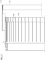
FIG. 1] Fig. 1 is a cross-sectional view taken on a cross-section including a rotation axis of an electrical rotating device according to a first embodiment. - [
FIG. 2] Fig. 2 is a cross-sectional view taken on a cross-section perpendicular to the rotation axis of the electrical rotating device. - [
FIG. 3] Fig. 3 is a partially exploded view of a partition wall in the electrical rotating device. - [
FIG. 4] Fig. 4 is a partially exploded view of a partition wall in an electrical rotating device according to a second embodiment. - [
FIG. 5] Fig. 5 is a partially exploded view of a partition wall in an electrical rotating device according to a third embodiment. - [
FIG. 6] Fig. 6 is a partially exploded view of a partition wall in an electrical rotating device according to a fourth embodiment. - Hereinafter, embodiments of an electrical rotating device 1 will be described with reference to the drawings.
- The electrical rotating device 1 according to a first embodiment will be described with reference to
Fig. 1 to Fig. 3 . As shown inFig. 1 , the electrical rotating device 1 functions as an SPM (Surface Permanent Magnet) type electricity generator. The electrical rotating device 1 includes astator 2 and arotor 3. InFig. 1 , therotor 3 is indicated by dotted lines. The electrical rotating device 1 is provided with a hollowcylindrical case 10. Thecase 10 houses thestator 2 androtor 3. More specifically, thestator 2 is fixedly held in thecase 10 with being contacted with an inner circumference of thecase 10. Both ends of arotary shaft 30 of therotor 3 are supported by thecase 10 via bearings, respectively. - The
rotor 3 is rotatably provided inside the hollowcylindrical stator 2. Therotor 3 is provided with therotary shaft 30, arotor core 31,permanent magnets 32, and asleeve 33. As shown inFig. 2 , therotor core 31 is fixed with therotary shaft 30. The pluralpermanent magnets 32 are fixed on an outer circumference of therotor core 31. Thepermanent magnets 32 are arranged in eight rows in a circumferential direction, and in each row, plural (e.g., four) of them are also aligned in an axial direction. - The
sleeve 33 is fixed on an outer side of thepermanent magnets 32 to prevent thepermanent magnets 32 from dropping out from therotor core 31 due to a centrifugal force caused by the rotations of therotor 3. Thesleeve 33 is formed of ferrous metal. On each outer surface of thepermanent magnets 32, pluralcoolant flow grooves 34 are formed in the axial direction. Thecoolant flow grooves 34 form liquid coolant flow passages between thepermanent magnets 32 and thesleeve 33. - On the other hand, the
stator 2 is provided with astator core 20 and astator coil 21. Thestator core 20 is configured of electromagnetic steel sheets laminated in the axial direction and has a hollowcylindrical yoke 20a and plural (e.g., twenty-four)teeth 20b protruding inwardly from thisyoke 20a in a radial direction of its hollow cylindrical shape. Aslot 20c is formed betweenadjacent teeth 20b. Thestator coil 21 is routed in theslot 20c. Thestator coil 21 is configured ofquadrangular wires 21a. A "quadrangular wire" has a quadrilateral cross section and is sometimes referred to as a flat wire or a rectangular wire. Thequadrangular wire 21a in the present embodiment has a trapezoidal cross section that narrows in its width inwardly in the radial direction in theslot 20c. - The
quadrangular wire 21a need not have the trapezoidal cross section atcoil ends 21b of the stator coil 21 (seeFig. 1 ), for example, it may have a rectangular cross section. Thecoil ends 21b are projected laterally outward from the ends of thestator core 20 in the direction of the rotation axis of therotor 3, respectively. - Each open end of the
teeth 20b is extended in the circumferential direction to form flanges. Each of theslots 20c has a trapezoidal cross section that is long in the radial direction. Each inner width of theslots 20c narrows toward the flanges, i.e., inwardly in the radial direction. Within each of theslots 20c, the fourquadrangular wires 21a with trapezoidal cross-sections are aligned in the radial direction. With respect to a circumferential width of thequadrangular wires 21a within theslots 20c, they gradually narrow inwardly in the radial direction in accordance with each width of theslots 20c. Radial heights of thequadrangular wires 21a in theslot 20c are gradually made larger as they go inward in the radial direction. Cross-sectional area of thequadrangular wires 21a in theslot 20c are approximately the same because of the widths and heights described above, and electrical resistance per length of thequadrangular wires 21a is approximately identical. - A
coolant flow groove 210 is formed on some of thequadrangular wires 21a, and thereby a flow passage for liquid coolant is formed between adjacentquadrangular wires 21a. The radially most inwardquadrangular wire 21a is received by the above-mentioned flanges at the open ends of theteeth 20b. Note that a gap is formed between opposed ends of the flanges, but this gap is closed by aceramic spacer 20d (seeFig. 2 ) that has a circular cross-section and extends in the axial direction. Thespacer 20d prevents later-described liquid coolant circulated inside thestator 2 from leaking into an inner space X where therotor 3 is accommodated. In the present embodiment, thespacer 20d is fixed to the teeth by adhesive. - The
stator core 20 is constructed from pluralcircumferential members 20X that form portions of theyoke 20a andradial members 20Y that form the remains of theyoke 20a and theteeth 20b. Since thestator core 20 is configured of the axially stacked electromagnetic steel sheets as described above, thecircumferential members 20X and theradial members 20Y are also configured of the axially stacked electromagnetic steel sheets. Thecircumferential members 20X and theradial members 20Y are arranged alternately in the circumferential direction to construct thestator core 20. Theyoke 20a is formed by thecircumferential members 20X and the outer circumferential portions of theradial members 20Y that are alternately arranged. Thecircumferential members 20X are located radially outside of theslots 20c and function as caps that retain thequadrangular wires 21a stored in theslots 20c from the outer side. - The
circumferential members 20X and theradial members 20Y, arranged alternately in the circumferential direction, are secured by thecase 10 from the outer side. On the outer circumference of thestator core 20,coolant flow grooves 23 through which the liquid coolant circulates are extended in the axial direction. Thecoolant flow grooves 23 form liquid coolant flow passages between thestator core 20 and thecase 10. - As shown in
Fig. 1 , the electrical rotating device 1 also includes a pair ofpartition walls 11 that partition an interior space of thecase 10 into the inner space X with respect to thestator 2 and accommodation spaces Y in which the coil ends 21b of thestator 2 are accommodated, respectively. Each of thepartition walls 11 is hollow cylindrical and made of electrically conductive metal. The accommodation spaces Y of the coil ends 21b are isolated by thepartition walls 11, and the two annular accommodation spaces Y are communicated with each other by the above-mentioned coolant flow grooves 210 (seeFig. 2 ).Supplemental partition walls 12 are also provided on a radially outer side of the accommodation spaces Y, respectively. The supplemental partition wall(s) 12 forms a supplemental space Z on the outer side of the accommodation space Y. The two annular supplemental spaces Z are communicated with each other by the above-mentioned coolant flow grooves 23 (seeFig. 2 ). - At one end of the
case 10, asupply port 16 is formed to supply the liquid coolant to the supplemental space Z. Plural throughholes 14 are formed on thesupplemental partition wall 12 at the other end of thecase 10 to allow the liquid coolant to flow from the other supplemental space Z to the accommodation space Y. The through holes 14 are spaced apart from one another in the circumferential direction. In addition, adischarge port 15 is formed at the one end of thecase 10 to discharge the liquid coolant from the accommodation space Y located at the one end. In the present embodiment, the liquid coolant is circulated in the accommodation spaces Y to suppress a decrease in efficiency of the electrical rotating device 1 due to high temperatures. Since the liquid coolant is not circulated or filled in the inner space X where therotor 3 is disposed, the liquid coolant does not generate a rotational resistance of therotor 3 and not cause the decrease in the efficiency of the electrical rotating device 1. Liquid sealing and circulation of the liquid coolant will be explained later. - The electrical rotating device 1 is operated by magnetic flux acting between the
stator 2 and therotor 3. This magnetic flux also affects outer areas from the ends of thestator 2 and therotor 3 in the axial direction. Therefore, the above-mentioned magnetic flux induces eddy currents inside thepartition walls 11 made of electrically conductive metal, and thereby the eddy currents cause eddy current losses. The eddy current losses, which are Joule heat losses, generate heat in thepartition walls 11 and decrease the efficiency of the electrical rotating device 1. In the present embodiment,slits 110a are formed in the partition wall(s) 11 as shown inFig. 3 to suppress the eddy current losses by reducing each size of eddies of the eddy currents inside thepartition wall 11. - Since a portion of the
partition wall 11 close to thestator 2 and therotor 3 is most affected by the magnetic flux, the portion of thepartition wall 11 close to thestator core 20 is divided into pluralsmall sections 111a by forming theslits 110a, and thereby voltage (induced electromotive force) induced in the small section(s) 111a is made smaller. It is known that (eddy current) = (induced electromotive force) × (resistance), so that magnitude of eddy currents is also affected by electrical resistance (conductivity of the material). Since eddy current loss is proportional to square of induced electromotive force and inversely proportional to resistance, the effect of the induced electromotive force is greater. Therefore, the formation of thesmall sections 111a reduces each size of eddies of the eddy currents and thereby the induced electromotive force is reduced, so that the eddy current loss can be effectively suppressed. Note thatFig. 3 shows a longitudinal cross-sectional view and only its upper half is illustrated. Its lower half is also symmetrically formed. - In the present embodiment, the
plural slits 110a extending in the axial direction of therotary shaft 30 are formed from the end edge of thepartition wall 11 close to thestator core 20 to segment the pluralsmall sections 111a in the circumferential direction of thepartition wall 11. Dividing the portion of thepartition wall 11, especially its portion susceptible to the magnetic flux, into the pluralsmall sections 111a in this manner can reduce each size of eddies of the eddy currents as indicated by an arrow EC inFig. 3 , and thereby the eddy current losses can be suppressed. As a result, the heat generated by the electrical resistance of thepartition wall 11 and the decrease in the efficiency of the electrical rotating device 1 can be suppressed. - Note that in the present embodiment, the
small sections 111a are divided so that their respective circumferential width is 2 to 15 mm. The eddy current losses can be suppressed by restricting each size of eddies of the eddy currents by dividing thesmall sections 111a to have such a size. - In addition, the liquid coolant circulates in the accommodation space(s) Y and the supplemental space(s) Z as described above, but it is needed that they are liquid-sealed to prevent the liquid coolant from leaking into the inner space X. Since the
slits 110a are formed in thepartition wall 11, the liquid coolant will leak from the accommodation space Y to the inner space X through theslits 110a without liquid-sealing. In the present embodiment, anannular seal member 112 having a U-shaped cross section is attached to the end edge of thepartition wall 11 close to thestator core 20. Theseal member 112 is made of rubber having elastic resilience and covers all thesmall sections 111a, i.e., all theslits 110a, from both the outer and inner circumferential surfaces of thepartition wall 11. However, theseal member 112 need only cover all thesmall sections 111a, i.e., all theslits 110a, from at least one of the outer and inner circumferential surfaces of thepartition wall 11. - The
seal member 112 prevents the liquid coolant from leaking through theslits 110a. Theseal member 112 in the present embodiment also has acircumferential edge 113 that is sandwiched between the end edge of thepartition wall 11 and the end face of thestator core 20. Thecircumferential edge 113 corresponds to a bent portion of the U-shaped cross section of theseal member 112. Thecircumferential edge 113 having elastic resilience is sandwiched between thepartition wall 11 and thestator core 20, and thereby the liquid coolant can be prevented from leaking out between thepartition wall 11 and thestator core 20. More particularly, thecircumferential edge 113 is pressed onto end faces of the teeth and thespacers 20d of thestator core 20 that are described above. - Note that the
seal member 112 need have the U-shaped cross-section as shown inFig. 3 at least in its installed state, and may have a flat sheet-shape before being installed on thepartition wall 11. In addition, theseal member 112 need have the annular form at least in its installed state, and may have a band shape having two ends before being installed. In such a case, theseal member 112 is attached to the end edge of thepartition wall 11 so that the two ends of the band shape are butted against each other so that no gap is created therebetween when being attached to the end edge of thepartition wall 11. - The circulation of the liquid coolant is described below. The liquid coolant is supplied from the
supply port 16 to the supplemental space Z on the left side inFig. 1 . The liquid coolant then flows through thecoolant flow grooves 23 to the supplemental space Z on the right side inFig. 1 while cooling thestator core 20. The liquid coolant then flows into the right-side accommodation space Y through the through holes 14. The right-side coil end 21b is cooled by the liquid coolant in the right-side accommodation space Y. Further, the liquid coolant flows to the accommodation space Y on the left side inFig. 1 through thecoolant flow grooves 210 while cooling thestator coil 21. Thestator core 20 is also cooled via thestator coil 21. The left-side coil end 21b is also cooled by the liquid coolant in the left-side accommodation space Y. - The liquid coolant in the left-side accommodation space Y is discharged from the
discharge port 15 to the outside of thecase 10. The liquid coolant flows in this manner but the liquid coolant does not leak out into the inner space X, because the accommodation spaces Y are isolated from the inner space X liquid-tightly by thepartition walls 11 each having theseal member 112. Although not explained in detail, the liquid coolant is also circulated through thecoolant flow grooves 34 of therotor 3 via the inside of therotary shaft 30. - Next, an electrical rotating device 1 according to a second embodiment will be described with reference to
Fig. 4. Fig. 4 is a drawing corresponding toFig. 3 of the first embodiment. In the electrical rotating device 1 according to the present embodiment, only itspartition walls 11 differ from thepartition walls 11 of the first embodiment. More specifically, only the divided form of the partition wall(s) 11 into thesmall sections 111b differs from the divided form into thesmall sections 111a in the first embodiment. Therefore, only the partition wall(s) 11 will be described below. The configurations other than the partition wall(s) 11 are the same as those in the first embodiment described above. - In the first embodiment, the portion of the
partition wall 11 close to thestator core 20 is divided into the pluralsmall sections 111a by forming theslits 110a. On the other hand, in the present embodiment, the portion of thepartition wall 11 close to thestator core 20 is divided into pluralsmall sections 111b by formingcontact surfaces 110b. More particularly, the portion of thepartition wall 11 close to thestator core 20 is formed by plural annular members that are aligned in the axial direction of the rotary shaft of therotor 3 and are in contact with each other, and thereby the pluralsmall sections 111b are segmented in the axial direction. That is, in the present embodiment, the annular members are thesmall sections 111b, so thereference number 111b is also used for the annular members. - Each of the
annular members 111b is coated with an insulating film to ensure electrical insulations between the main body of thepartition wall 11 and theannular member 111b and between adjacentannular members 111b. Therefore, each size of the eddies of the eddy currents can be reduced due to the restriction of the eddy currents within each width of the annular members 1 1 1b, and thereby the eddy current losses can be suppressed. As a result, the heat generated by the electrical resistance in thepartition wall 11 and thereby the decrease in the efficiency of the electrical rotating device 1 can be suppressed. In the present embodiment, the contact surfaces 110b between the main body of thepartition wall 11 and theannular member 111b and between the adjacentannular members 111b are bonded by an adhesive. If electrical insulation can be ensured by the adhesive, the insulating film need not be provided. Since the electrical resistance will increase even when the contact surfaces 110b are simply brought into contact with each other with no insulating film nor the adhesive layer, each size of the eddies of the eddy currents can be reduced. - Each width of the
annular members 111b in the present embodiment is about 0.1 to 15 mm. Also in the present embodiment, provided is theseal member 112 that covers all theannular members 111b as the small sections from both the outer and inner circumferential surfaces of thepartition wall 11, i.e., covers all the contact surfaces 110b. Theseal member 112 need only cover all thesmall sections 111b, i.e., cover all the contact surfaces 110b, from at least one of the outer and inner circumferential surfaces of thepartition wall 11. Therefore, theseal member 112 prevents the liquid coolant from leaking through the contact surfaces 110b. The liquid coolant can be prevented from leaking out between thepartition wall 11 and thestator core 20 by thecircumferential edge 113 of theseal member 112. - Next, an electrical rotating device 1 according to a third embodiment will be described with reference to
Fig. 5. Fig. 5 is also a drawing corresponding toFig. 3 of the first embodiment. In the electrical rotating device 1 according to the present embodiment, itspartition walls 11 and itsseal member 112 differ from thepartition walls 11 and theseal member 112 of the first embodiment. Therefore, only the partition wall(s) 11 and the seal member(s) 112 will be described below. - In the electrical rotating device 1 according to the present embodiment, each length of the
slits 110a differs from that in thepartition wall 11 of the first embodiment. As mentioned above, the portion of thepartition wall 11 close to thestator 2 and therotor 3 is most affected by the magnetic flux, but the eddy current loss can be more suppressed compared to the first embodiment by also dividing a portion far from thestator 2 and therotor 3 into thesmall sections 111a. As a result, the heat generated by the electrical resistance in thepartition wall 11 and the decrease in the efficiency of the electrical rotating device 1 can be more suppressed. - Since each of the
small sections 111a is made larger than that in the first embodiment, theseal member 112 for covering them is also made larger. In the present embodiment, theseal member 112 has a J-shaped cross section and covers all thesmall sections 111a, i.e., all theslits 110a, from the outer circumferential surface of thepartition wall 11. Therefore, theseal member 112 prevents the liquid coolant from leaking through theslits 110a. Note that theseal member 112 covers only part of thesmall sections 111a, i.e., part of theslits 110a, from the inner circumferential surface of thepartition wall 11. However, since the free ends of thesmall sections 111a are covered by theseal member 112 from both the outer and inner circumferential surfaces, the rigidity of thepartition wall 11 can be prevented from decreasing. It is same as the first embodiment that theseal member 112 is provided with thecircumferential edge 113, and thereby the liquid coolant can be prevented from leaking out between thepartition wall 11 and thestator core 20. - Next, an electrical rotating device 1 according to a fourth embodiment will be described with reference to
Fig. 6. Fig. 6 is also a drawing corresponding toFig. 3 of the first embodiment. Also in the electrical rotating device 1 according to the present embodiment, itspartition walls 11 differ from thepartition walls 11 of the first embodiment. Theseal member 112 is the same as theseal member 112 of the third embodiment. Therefore, only the partition wall(s) 11 will be described below. - In the above-described second embodiment, the portion of the
partition wall 11 is divided into the pluralsmall sections 111b by forming the contact surfaces 110b extending in the circumferential direction. In the present embodiment,plural slits 110c extending in the circumferential direction are formed over almost the entire of thepartition wall 11 along the axial direction, so that the plural small sections 111c are segmented in the axial direction of therotary shaft 30 of therotor 3. Each width of the small sections 111c in the present embodiment is about 0.1 to 15 mm. Note that theslits 110c should be formed at least at the portion of thepartition wall 11 closer to thestator core 20, which is susceptible to the magnetic flux as described above. - Each
slit 110c is formed only on approximately half circumference of thepartition wall 11 and theannular members 111b independent from each other like as in the second embodiment are not formed. In the present embodiment, the plural small sections 111c are monolithically jointed withjoint portions 114 in which theslits 110c are not formed. Thejoint portions 114 are provided at two opposite locations in the hollowcylindrical partition wall 11. Theseal member 112 has a J-shaped cross-section as in the third embodiment, and covers all the small sections 111c, i.e., all theslits 110c from the outer circumferential surface of thepartition wall 11. Theseal member 112 is also provided with thecircumferential edge 113. - According to the first to fourth embodiments, the accommodation space Y in which the
coil end 21b is accommodated and the liquid coolant is circulated is formed by the hollowcylindrical partition wall 11 made of electrically conductive metal. Therefore, thecoil end 21b can be effectively cooled and the decrease in the efficiency of the electrical rotating device 1 can be suppressed. - In addition, at least the portion of the
partition wall 11 close to thestator core 20 is divided into the pluralsmall sections 111a-111c by forming theslits partition wall 11 and the decrease in the efficiency of the electrical rotating device 1 can be suppressed. - Here, the
small sections 111a-111c are formed at least at the portion of thepartition wall 11 close to thestator core 20. Therefore, the eddy current losses can be effectively suppressed in such portion where the eddy currents are easily formed under the influence of magnetic flux. - According to the first and third embodiments, the
plural slits 110a extending in the axial direction of therotary shaft 30 are formed from the end edge of thepartition wall 11 close to thestator core 20 and thereby the pluralsmall sections 111a are divided in the circumferential direction of thepartition wall 11. Theslits 110a like these can be easily formed by machine work. Since thesmall sections 111a can be formed integrally with the main body of thepartition wall 11, the position shift of thesmall sections 111a can be minimized and thereby a shape change of thepartition wall 11 can be effectively suppressed. By the suppression of the shape change of thepartition wall 11, the liquid coolant can be effectively prevented from leaking from the accommodation space Y. - According to the second embodiment, at least the portion of the
partition wall 11 close to thestator core 20 is configured of the pluralannular members 111b that are aligned in the axial direction of therotary shaft 30 and made in contact with each other, and thereby the pluralsmall sections 111b are segmented in the axial direction. Therefore, theannular members 111b, i.e., thesmall sections 111b, like these have an annular shape completely continuous over the entire circumference, so that they can effectively withstand the pressure of the liquid coolant in the accommodation space Y. - According to the fourth embodiment, the
plural slits 110c extending in the circumferential direction of thepartition wall 11 are formed at least at the portion of thepartition wall 11 close to thestator core 20, so that the plural small sections 111c are divided in the axial direction of therotary shaft 30. Theslits 110c like these can be also easily formed by machine work. Since the small sections 111c can be formed integrally with the main body of thepartition wall 11, the position shift of the small sections 111c can be minimized and thereby a shape change of thepartition wall 11 can be effectively suppressed to prevent the liquid coolant effectively from leaking from the accommodation space Y. Furthermore, the small sections 111c have an annular shape completely continuous over the entire circumference, so that they can effectively withstand the pressure of the liquid coolant in the accommodation space Y. - In addition, according to the first to fourth embodiments, the electrical rotating device 1 further includes the
annular seal member 112 that covers all thesmall sections 111a to 111c from at least one of the outer and inner circumferential surfaces of thepartition wall 11. Therefore, the leakage of the liquid coolant through theslits seal member 112. Furthermore, theseal member 112 has thecircumferential edge 113 that is sandwiched between the edge of thepartition wall 11 and the end face of thestator core 20. Therefore, the liquid coolant can be reliably prevented from leaking out between thepartition wall 11 and thestator core 20 by thecircumferential edge 113 of theseal member 112. - Note that, in the first, third and fourth embodiments, the leakage of the liquid coolant into the inner space X through the
slits seal member 112 that covers all thesmall sections 111a to 111c. However, the leakage may be prevented by filling resin only inside theslits - The present application claims a priority based on a
Japanese Patent Application No. 2022-20442, file on February 14, 2022 -
- 1 electrical rotating device
- 2 stator
- 3 rotor
- 10 case
- 11 partition wall
- 20 stator core
- 21 stator core
- 21b coil end
- 30 rotary shaft (of the rotor 3)
- 110a, 110c slit
- 110b contact surface
- 111a-111c small section
- 111b annular member (as the small section)
- 112 seal member
- 113 circumferential edge
- X inner space
- Y accommodation space
Claims (5)
- An electrical rotating device comprising:a hollow cylindrical stator provided with a stator core and a stator coil;a rotor provided rotatably inside the stator;a case that houses the stator and the rotor; anda hollow cylindrical partition wall that is made of electrically conductive metal and partitions an interior space of the case into an inner space with respect to the stator and an accommodation space in which a coil end of the stator is accommodated and liquid coolant is circulated,wherein at least a portion of the partition wall close to the stator core is divided into a plurality of small sections by forming a plurality of slits or contact surfaces.
- The electrical rotating device according to claim 1, wherein
the plurality of slits extending in an axial direction of a rotary shaft of the rotor is formed from an end edge of the partition wall closer to the stator core to segment the plurality of small sections in a circumferential direction of the partition wall. - The electrical rotating device according to claim 1, wherein
the portion of the partition wall close to the stator core is configured of a plurality of annular members that are aligned in an axial direction of a rotary shaft of the rotor and made in contact with each other to segment the plurality of small sections in the axial direction. - The electrical rotating device according to claim 1, wherein
the plurality of slits extending in a circumferential direction of the partition wall is formed at least at the portion of the partition wall close to the stator core to segment the plurality of small sections in an axial direction of a rotary shaft of the rotor. - The electrical rotating device according to according to any one of claims 2 to 4, further comprisinga seal member that has an annular shape and covers all the small sections from at least one of outer and inner circumferential surfaces of the partition wall,wherein the seal member has a circumferential edge that is sandwiched between an end edge of the partition wall close to the stator core and an end face of the stator core.
Applications Claiming Priority (2)
| Application Number | Priority Date | Filing Date | Title |
|---|---|---|---|
| JP2022020442 | 2022-02-14 | ||
| PCT/JP2022/042962 WO2023153043A1 (en) | 2022-02-14 | 2022-11-21 | Rotating electric machine |
Publications (2)
| Publication Number | Publication Date |
|---|---|
| EP4482000A1 true EP4482000A1 (en) | 2024-12-25 |
| EP4482000A4 EP4482000A4 (en) | 2026-02-18 |
Family
ID=87564115
Family Applications (1)
| Application Number | Title | Priority Date | Filing Date |
|---|---|---|---|
| EP22926059.1A Pending EP4482000A4 (en) | 2022-02-14 | 2022-11-21 | ELECTRIC LATHE |
Country Status (5)
| Country | Link |
|---|---|
| US (1) | US20240243630A1 (en) |
| EP (1) | EP4482000A4 (en) |
| JP (1) | JP7816389B2 (en) |
| CA (1) | CA3235599A1 (en) |
| WO (1) | WO2023153043A1 (en) |
Families Citing this family (1)
| Publication number | Priority date | Publication date | Assignee | Title |
|---|---|---|---|---|
| WO2025203204A1 (en) * | 2024-03-26 | 2025-10-02 | ファナック株式会社 | Stator with cooling structure, and electric motor |
Family Cites Families (12)
| Publication number | Priority date | Publication date | Assignee | Title |
|---|---|---|---|---|
| JP2003042155A (en) | 2001-07-30 | 2003-02-13 | Shimadzu Corp | Magnetic bearing device |
| JP3815274B2 (en) * | 2001-08-08 | 2006-08-30 | 株式会社明電舎 | Can fixing method for high-speed rotating electric machine |
| US6933633B2 (en) * | 2001-10-03 | 2005-08-23 | Nissan Motor Co., Ltd. | Rotating electric machine and cooling structure for rotating electric machine |
| JP3823844B2 (en) * | 2002-02-22 | 2006-09-20 | 日産自動車株式会社 | Rotating electric machine and manufacturing method thereof |
| JP3896882B2 (en) * | 2002-03-28 | 2007-03-22 | 日産自動車株式会社 | Rotating electric machine |
| DE102009052932A1 (en) * | 2009-11-12 | 2011-06-01 | Siemens Aktiengesellschaft | Electrical machine, in particular canned electric motor |
| KR101475369B1 (en) * | 2010-12-22 | 2014-12-23 | 가부시키가이샤 아이에이치아이 | Rotary machine |
| EP2689515B1 (en) * | 2011-03-23 | 2020-06-24 | Nuovo Pignone S.p.A. | Elastic cone for hermetically sealed stator, corresponding motor and manfacturing method |
| CN105471131B (en) * | 2016-01-19 | 2023-08-25 | 凯博易控驱动(苏州)股份有限公司 | Cooling mechanism for stator in oil immersed motor |
| WO2019238365A1 (en) * | 2018-06-12 | 2019-12-19 | Magna powertrain gmbh & co kg | Rotating electrical machine, electric motor, vehicle having an electric drive, can and production method for same |
| JP7544521B2 (en) | 2020-07-20 | 2024-09-03 | Fdk株式会社 | Control device, battery pack and power supply device |
| EP3972095A1 (en) * | 2020-09-18 | 2022-03-23 | Siemens Aktiengesellschaft | Gap tube of a dynamo-electric machine |
-
2022
- 2022-11-21 WO PCT/JP2022/042962 patent/WO2023153043A1/en not_active Ceased
- 2022-11-21 EP EP22926059.1A patent/EP4482000A4/en active Pending
- 2022-11-21 CA CA3235599A patent/CA3235599A1/en active Pending
- 2022-11-21 JP JP2023580078A patent/JP7816389B2/en active Active
-
2024
- 2024-04-01 US US18/623,122 patent/US20240243630A1/en active Pending
Also Published As
| Publication number | Publication date |
|---|---|
| WO2023153043A1 (en) | 2023-08-17 |
| JPWO2023153043A1 (en) | 2023-08-17 |
| EP4482000A4 (en) | 2026-02-18 |
| JP7816389B2 (en) | 2026-02-18 |
| US20240243630A1 (en) | 2024-07-18 |
| CA3235599A1 (en) | 2023-08-17 |
Similar Documents
| Publication | Publication Date | Title |
|---|---|---|
| KR101475369B1 (en) | Rotary machine | |
| US10361597B2 (en) | Electric machine for a motor vehicle, coil carrier for an electric machine, and motor vehicle | |
| CN113224870B (en) | Rotating electric machines | |
| EP2853017B1 (en) | Stator of a rotating electric machine | |
| US12142982B2 (en) | Stator and rotary electric machine | |
| CN109075653B (en) | Rotary electric machines with optimized cooling | |
| WO2021229888A1 (en) | Electric motor stator and electric motor | |
| US20240243630A1 (en) | Electrical rotating device | |
| WO2019159522A1 (en) | Cooling structure for rotary electric machine | |
| US20240195242A1 (en) | Motor | |
| EP3518392B1 (en) | Motor | |
| WO2023106338A1 (en) | Motor | |
| CN116896185A (en) | Rotor and rotating electrical machine | |
| US20250309710A1 (en) | Rotor and rotary electric machine | |
| JP7767175B2 (en) | Cooling structure for rotating electrical machines | |
| EP4593256A1 (en) | Permanent magnet rotor for an electric machine | |
| JP7424439B1 (en) | rotating electric machine | |
| JP2023118449A (en) | Cooling structure in rotating electric machine | |
| JP2023061074A (en) | Buried-type magnetic motor | |
| CN116896184A (en) | Rotor and rotating electrical machine | |
| JP2024089799A (en) | Rotating Electric Machine | |
| CN116827009A (en) | Rotary electric machine |
Legal Events
| Date | Code | Title | Description |
|---|---|---|---|
| STAA | Information on the status of an ep patent application or granted ep patent |
Free format text: STATUS: THE INTERNATIONAL PUBLICATION HAS BEEN MADE |
|
| PUAI | Public reference made under article 153(3) epc to a published international application that has entered the european phase |
Free format text: ORIGINAL CODE: 0009012 |
|
| STAA | Information on the status of an ep patent application or granted ep patent |
Free format text: STATUS: REQUEST FOR EXAMINATION WAS MADE |
|
| 17P | Request for examination filed |
Effective date: 20240328 |
|
| AK | Designated contracting states |
Kind code of ref document: A1 Designated state(s): AL AT BE BG CH CY CZ DE DK EE ES FI FR GB GR HR HU IE IS IT LI LT LU LV MC ME MK MT NL NO PL PT RO RS SE SI SK SM TR |
|
| DAV | Request for validation of the european patent (deleted) | ||
| DAX | Request for extension of the european patent (deleted) | ||
| A4 | Supplementary search report drawn up and despatched |
Effective date: 20260115 |
|
| RIC1 | Information provided on ipc code assigned before grant |
Ipc: H02K 9/197 20060101AFI20260109BHEP Ipc: H02K 9/19 20060101ALI20260109BHEP Ipc: H02K 1/32 20060101ALI20260109BHEP Ipc: H02K 5/10 20060101ALI20260109BHEP Ipc: H02K 5/20 20060101ALI20260109BHEP |