EP4481976A1 - Bi-directional battery charging system for one or more transport refrigeration unit - Google Patents
Bi-directional battery charging system for one or more transport refrigeration unit Download PDFInfo
- Publication number
- EP4481976A1 EP4481976A1 EP24182228.7A EP24182228A EP4481976A1 EP 4481976 A1 EP4481976 A1 EP 4481976A1 EP 24182228 A EP24182228 A EP 24182228A EP 4481976 A1 EP4481976 A1 EP 4481976A1
- Authority
- EP
- European Patent Office
- Prior art keywords
- battery
- tru
- directional
- electrical power
- trus
- Prior art date
- Legal status (The legal status is an assumption and is not a legal conclusion. Google has not performed a legal analysis and makes no representation as to the accuracy of the status listed.)
- Pending
Links
Images




Classifications
-
- B—PERFORMING OPERATIONS; TRANSPORTING
- B60—VEHICLES IN GENERAL
- B60P—VEHICLES ADAPTED FOR LOAD TRANSPORTATION OR TO TRANSPORT, TO CARRY, OR TO COMPRISE SPECIAL LOADS OR OBJECTS
- B60P3/00—Vehicles adapted to transport, to carry or to comprise special loads or objects
- B60P3/20—Refrigerated goods vehicles
-
- H—ELECTRICITY
- H02—GENERATION; CONVERSION OR DISTRIBUTION OF ELECTRIC POWER
- H02J—ELECTRIC POWER NETWORKS; CIRCUIT ARRANGEMENTS OR SYSTEMS FOR SUPPLYING OR DISTRIBUTING ELECTRIC POWER; SYSTEMS FOR STORING ELECTRIC ENERGY
- H02J7/00—Circuit arrangements for charging or discharging batteries or for supplying loads from batteries
- H02J7/34—Parallel operation in networks using both storage and other DC sources, e.g. providing buffering
- H02J7/342—The other DC source being a battery actively interacting with the first one, i.e. battery to battery charging
-
- B—PERFORMING OPERATIONS; TRANSPORTING
- B60—VEHICLES IN GENERAL
- B60H—ARRANGEMENTS OF HEATING, COOLING, VENTILATING OR OTHER AIR-TREATING DEVICES SPECIALLY ADAPTED FOR PASSENGER OR GOODS SPACES OF VEHICLES
- B60H1/00—Heating, cooling or ventilating devices
- B60H1/32—Cooling devices
- B60H1/3204—Cooling devices using compression
- B60H1/3226—Self-contained devices, i.e. including own drive motor
-
- B—PERFORMING OPERATIONS; TRANSPORTING
- B60—VEHICLES IN GENERAL
- B60L—PROPULSION OF ELECTRICALLY-PROPELLED VEHICLES; SUPPLYING ELECTRIC POWER FOR AUXILIARY EQUIPMENT OF ELECTRICALLY-PROPELLED VEHICLES; ELECTRODYNAMIC BRAKE SYSTEMS FOR VEHICLES IN GENERAL; MAGNETIC SUSPENSION OR LEVITATION FOR VEHICLES; MONITORING OPERATING VARIABLES OF ELECTRICALLY-PROPELLED VEHICLES; ELECTRIC SAFETY DEVICES FOR ELECTRICALLY-PROPELLED VEHICLES
- B60L53/00—Methods of charging batteries, specially adapted for electric vehicles; Charging stations or on-board charging equipment therefor; Exchange of energy storage elements in electric vehicles
- B60L53/50—Charging stations characterised by energy-storage or power-generation means
- B60L53/57—Charging stations without connection to power networks
-
- B—PERFORMING OPERATIONS; TRANSPORTING
- B60—VEHICLES IN GENERAL
- B60L—PROPULSION OF ELECTRICALLY-PROPELLED VEHICLES; SUPPLYING ELECTRIC POWER FOR AUXILIARY EQUIPMENT OF ELECTRICALLY-PROPELLED VEHICLES; ELECTRODYNAMIC BRAKE SYSTEMS FOR VEHICLES IN GENERAL; MAGNETIC SUSPENSION OR LEVITATION FOR VEHICLES; MONITORING OPERATING VARIABLES OF ELECTRICALLY-PROPELLED VEHICLES; ELECTRIC SAFETY DEVICES FOR ELECTRICALLY-PROPELLED VEHICLES
- B60L53/00—Methods of charging batteries, specially adapted for electric vehicles; Charging stations or on-board charging equipment therefor; Exchange of energy storage elements in electric vehicles
- B60L53/60—Monitoring or controlling charging stations
- B60L53/67—Controlling two or more charging stations
-
- B—PERFORMING OPERATIONS; TRANSPORTING
- B60—VEHICLES IN GENERAL
- B60L—PROPULSION OF ELECTRICALLY-PROPELLED VEHICLES; SUPPLYING ELECTRIC POWER FOR AUXILIARY EQUIPMENT OF ELECTRICALLY-PROPELLED VEHICLES; ELECTRODYNAMIC BRAKE SYSTEMS FOR VEHICLES IN GENERAL; MAGNETIC SUSPENSION OR LEVITATION FOR VEHICLES; MONITORING OPERATING VARIABLES OF ELECTRICALLY-PROPELLED VEHICLES; ELECTRIC SAFETY DEVICES FOR ELECTRICALLY-PROPELLED VEHICLES
- B60L55/00—Arrangements for supplying energy stored within a vehicle to a power network, i.e. vehicle-to-grid [V2G] arrangements
-
- B—PERFORMING OPERATIONS; TRANSPORTING
- B60—VEHICLES IN GENERAL
- B60R—VEHICLES, VEHICLE FITTINGS, OR VEHICLE PARTS, NOT OTHERWISE PROVIDED FOR
- B60R16/00—Electric or fluid circuits specially adapted for vehicles and not otherwise provided for; Arrangement of elements of electric or fluid circuits specially adapted for vehicles and not otherwise provided for
- B60R16/02—Electric or fluid circuits specially adapted for vehicles and not otherwise provided for; Arrangement of elements of electric or fluid circuits specially adapted for vehicles and not otherwise provided for electric constitutive elements
- B60R16/03—Electric or fluid circuits specially adapted for vehicles and not otherwise provided for; Arrangement of elements of electric or fluid circuits specially adapted for vehicles and not otherwise provided for electric constitutive elements for supply of electrical power to vehicle subsystems or for
- B60R16/033—Electric or fluid circuits specially adapted for vehicles and not otherwise provided for; Arrangement of elements of electric or fluid circuits specially adapted for vehicles and not otherwise provided for electric constitutive elements for supply of electrical power to vehicle subsystems or for characterised by the use of electrical cells or batteries
-
- H—ELECTRICITY
- H02—GENERATION; CONVERSION OR DISTRIBUTION OF ELECTRIC POWER
- H02J—ELECTRIC POWER NETWORKS; CIRCUIT ARRANGEMENTS OR SYSTEMS FOR SUPPLYING OR DISTRIBUTING ELECTRIC POWER; SYSTEMS FOR STORING ELECTRIC ENERGY
- H02J3/00—Circuit arrangements for AC mains or AC distribution networks
- H02J3/28—Arrangements for balancing of the load in networks by storage of energy
- H02J3/32—Arrangements for balancing of the load in networks by storage of energy using batteries or super capacitors with converting means
-
- H—ELECTRICITY
- H02—GENERATION; CONVERSION OR DISTRIBUTION OF ELECTRIC POWER
- H02J—ELECTRIC POWER NETWORKS; CIRCUIT ARRANGEMENTS OR SYSTEMS FOR SUPPLYING OR DISTRIBUTING ELECTRIC POWER; SYSTEMS FOR STORING ELECTRIC ENERGY
- H02J3/00—Circuit arrangements for AC mains or AC distribution networks
- H02J3/28—Arrangements for balancing of the load in networks by storage of energy
- H02J3/32—Arrangements for balancing of the load in networks by storage of energy using batteries or super capacitors with converting means
- H02J3/322—Arrangements for balancing of the load in networks by storage of energy using batteries or super capacitors with converting means the battery being on-board an electric or hybrid vehicle, e.g. vehicle to grid arrangements [V2G], power aggregation, use of the battery for network load balancing, coordinated or cooperative battery charging
-
- H—ELECTRICITY
- H02—GENERATION; CONVERSION OR DISTRIBUTION OF ELECTRIC POWER
- H02J—ELECTRIC POWER NETWORKS; CIRCUIT ARRANGEMENTS OR SYSTEMS FOR SUPPLYING OR DISTRIBUTING ELECTRIC POWER; SYSTEMS FOR STORING ELECTRIC ENERGY
- H02J7/00—Circuit arrangements for charging or discharging batteries or for supplying loads from batteries
- H02J7/02—Circuit arrangements for charging or discharging batteries or for supplying loads from batteries for charging batteries from AC mains by converters
-
- H—ELECTRICITY
- H02—GENERATION; CONVERSION OR DISTRIBUTION OF ELECTRIC POWER
- H02J—ELECTRIC POWER NETWORKS; CIRCUIT ARRANGEMENTS OR SYSTEMS FOR SUPPLYING OR DISTRIBUTING ELECTRIC POWER; SYSTEMS FOR STORING ELECTRIC ENERGY
- H02J7/00—Circuit arrangements for charging or discharging batteries or for supplying loads from batteries
- H02J7/02—Circuit arrangements for charging or discharging batteries or for supplying loads from batteries for charging batteries from AC mains by converters
- H02J7/04—Regulation of charging current or voltage
-
- H—ELECTRICITY
- H02—GENERATION; CONVERSION OR DISTRIBUTION OF ELECTRIC POWER
- H02J—ELECTRIC POWER NETWORKS; CIRCUIT ARRANGEMENTS OR SYSTEMS FOR SUPPLYING OR DISTRIBUTING ELECTRIC POWER; SYSTEMS FOR STORING ELECTRIC ENERGY
- H02J7/00—Circuit arrangements for charging or discharging batteries or for supplying loads from batteries
- H02J7/60—Circuit arrangements for charging or discharging batteries or for supplying loads from batteries including safety or protection arrangements
- H02J7/61—Circuit arrangements for charging or discharging batteries or for supplying loads from batteries including safety or protection arrangements against overcharge
-
- H—ELECTRICITY
- H02—GENERATION; CONVERSION OR DISTRIBUTION OF ELECTRIC POWER
- H02J—ELECTRIC POWER NETWORKS; CIRCUIT ARRANGEMENTS OR SYSTEMS FOR SUPPLYING OR DISTRIBUTING ELECTRIC POWER; SYSTEMS FOR STORING ELECTRIC ENERGY
- H02J7/00—Circuit arrangements for charging or discharging batteries or for supplying loads from batteries
- H02J7/60—Circuit arrangements for charging or discharging batteries or for supplying loads from batteries including safety or protection arrangements
- H02J7/62—Circuit arrangements for charging or discharging batteries or for supplying loads from batteries including safety or protection arrangements against overcurrent
-
- H—ELECTRICITY
- H02—GENERATION; CONVERSION OR DISTRIBUTION OF ELECTRIC POWER
- H02J—ELECTRIC POWER NETWORKS; CIRCUIT ARRANGEMENTS OR SYSTEMS FOR SUPPLYING OR DISTRIBUTING ELECTRIC POWER; SYSTEMS FOR STORING ELECTRIC ENERGY
- H02J7/00—Circuit arrangements for charging or discharging batteries or for supplying loads from batteries
- H02J7/60—Circuit arrangements for charging or discharging batteries or for supplying loads from batteries including safety or protection arrangements
- H02J7/64—Circuit arrangements for charging or discharging batteries or for supplying loads from batteries including safety or protection arrangements against overvoltage
-
- H—ELECTRICITY
- H02—GENERATION; CONVERSION OR DISTRIBUTION OF ELECTRIC POWER
- H02J—ELECTRIC POWER NETWORKS; CIRCUIT ARRANGEMENTS OR SYSTEMS FOR SUPPLYING OR DISTRIBUTING ELECTRIC POWER; SYSTEMS FOR STORING ELECTRIC ENERGY
- H02J7/00—Circuit arrangements for charging or discharging batteries or for supplying loads from batteries
- H02J7/60—Circuit arrangements for charging or discharging batteries or for supplying loads from batteries including safety or protection arrangements
- H02J7/65—Circuit arrangements for charging or discharging batteries or for supplying loads from batteries including safety or protection arrangements against overtemperature
-
- H—ELECTRICITY
- H02—GENERATION; CONVERSION OR DISTRIBUTION OF ELECTRIC POWER
- H02J—ELECTRIC POWER NETWORKS; CIRCUIT ARRANGEMENTS OR SYSTEMS FOR SUPPLYING OR DISTRIBUTING ELECTRIC POWER; SYSTEMS FOR STORING ELECTRIC ENERGY
- H02J7/00—Circuit arrangements for charging or discharging batteries or for supplying loads from batteries
- H02J7/80—Circuit arrangements for charging or discharging batteries or for supplying loads from batteries including monitoring or indicating arrangements
-
- H—ELECTRICITY
- H02—GENERATION; CONVERSION OR DISTRIBUTION OF ELECTRIC POWER
- H02J—ELECTRIC POWER NETWORKS; CIRCUIT ARRANGEMENTS OR SYSTEMS FOR SUPPLYING OR DISTRIBUTING ELECTRIC POWER; SYSTEMS FOR STORING ELECTRIC ENERGY
- H02J7/00—Circuit arrangements for charging or discharging batteries or for supplying loads from batteries
- H02J7/80—Circuit arrangements for charging or discharging batteries or for supplying loads from batteries including monitoring or indicating arrangements
- H02J7/82—Control of state of charge [SOC]
-
- H—ELECTRICITY
- H02—GENERATION; CONVERSION OR DISTRIBUTION OF ELECTRIC POWER
- H02J—ELECTRIC POWER NETWORKS; CIRCUIT ARRANGEMENTS OR SYSTEMS FOR SUPPLYING OR DISTRIBUTING ELECTRIC POWER; SYSTEMS FOR STORING ELECTRIC ENERGY
- H02J7/00—Circuit arrangements for charging or discharging batteries or for supplying loads from batteries
- H02J7/865—Battery or charger load switching, e.g. concurrent charging and load supply
-
- B—PERFORMING OPERATIONS; TRANSPORTING
- B60—VEHICLES IN GENERAL
- B60H—ARRANGEMENTS OF HEATING, COOLING, VENTILATING OR OTHER AIR-TREATING DEVICES SPECIALLY ADAPTED FOR PASSENGER OR GOODS SPACES OF VEHICLES
- B60H1/00—Heating, cooling or ventilating devices
- B60H1/32—Cooling devices
- B60H2001/3286—Constructional features
- B60H2001/3292—Compressor drive is electric only
-
- B—PERFORMING OPERATIONS; TRANSPORTING
- B60—VEHICLES IN GENERAL
- B60L—PROPULSION OF ELECTRICALLY-PROPELLED VEHICLES; SUPPLYING ELECTRIC POWER FOR AUXILIARY EQUIPMENT OF ELECTRICALLY-PROPELLED VEHICLES; ELECTRODYNAMIC BRAKE SYSTEMS FOR VEHICLES IN GENERAL; MAGNETIC SUSPENSION OR LEVITATION FOR VEHICLES; MONITORING OPERATING VARIABLES OF ELECTRICALLY-PROPELLED VEHICLES; ELECTRIC SAFETY DEVICES FOR ELECTRICALLY-PROPELLED VEHICLES
- B60L2200/00—Type of vehicles
- B60L2200/36—Vehicles designed to transport cargo, e.g. trucks
-
- H—ELECTRICITY
- H02—GENERATION; CONVERSION OR DISTRIBUTION OF ELECTRIC POWER
- H02J—ELECTRIC POWER NETWORKS; CIRCUIT ARRANGEMENTS OR SYSTEMS FOR SUPPLYING OR DISTRIBUTING ELECTRIC POWER; SYSTEMS FOR STORING ELECTRIC ENERGY
- H02J2207/00—Details of circuit arrangements for charging or discharging batteries or supplying loads from batteries
- H02J2207/20—Charging or discharging characterised by the power electronics converter
Definitions
- This invention relates to transport refrigeration units and battery management systems.
- Transport refrigeration units may be used to conserve and maintain the temperature of perishable goods during transportation.
- Battery-powered TRUs may generally be employed for storing and transporting perishable goods while restricting emissions and lowering environmental impact.
- the battery associated with a battery-powered TRU may run low, which may affect the stored goods.
- the charging system of existing battery-powered TRU may allow the battery to recharge only through an external power supply which may not be available at all places.
- a first transport refrigeration unit comprising a bi-directional battery charging system.
- the bi-directional battery charging system comprises a bi-directional charger operatively connected to a controller and a battery associated with the first TRU, wherein the bi-directional charger is configured to be electrically connected to an external electrical component selected from the group consisting of an electrical grid, a battery associated with a second TRU, a battery associated with a vehicle, and combinations thereof.
- a bi-directional battery charging system for a first transport refrigeration unit (TRU), the bi-directional battery charging system comprising: a bi-directional charger operatively connected to a controller and a battery associated with the first TRU, wherein the bi-directional charger is configured to be electrically connected to an external electrical component selected from the group of an electrical grid, a battery associated with a second TRU, a battery associated with vehicles, and a combination thereof.
- TRU transport refrigeration unit
- the bi-directional charger enables supply of electrical power from the external electrical component to the battery associated with the first TRU.
- the bi-directional charger enables supply of electrical power from the battery associated with the first TRU to the external electrical component.
- the bi-directional charger comprises an AC to DC (ADC) converter configured to convert AC electrical power received from the external electrical component into DC electrical power for the battery associated with the first TRU, and a DC to AC (DAC) converter configured to convert DC electrical power supplied by the battery associated with the first TRU into AC electrical power for the external electrical component.
- ADC AC to DC
- DAC DC to AC
- the bi-directional charger comprises one or more AC to AC converters configured to convert AC electrical power having first electrical attributes received from the external electrical component into AC electrical power having second electrical attributes for the battery associated with the first TRU, and convert AC electrical power having the second electrical attributes supplied by the battery associated with the first TRU into AC electrical power having first electrical attributes for the external electrical component.
- the bi-directional charger comprises one or more DC to DC converters configured to convert DC electrical power having first electrical attributes being received from the external electrical component into DC electrical power having second electrical attributes for the battery associated with the first TRU, and convert DC electrical power having the second electrical attributes supplied by the battery associated with the first TRU into DC electrical power having first electrical attributes for the external electrical component.
- the bi-directional battery charging system comprises a battery management system (BMS) associated with the TRU, wherein the BMS comprises a DAC converter configured to convert DC electrical power supplied by the bi-directional charger into AC electrical power for one or more components of the first TRU and the battery associated with the first TRU.
- BMS battery management system
- the BMS comprises an ADC converter to convert AC electrical power supplied by the bi-directional charger into DC electrical power for one or more components of the TRU and the battery associated with the first TRU.
- the BMS comprises one or more sensors to: monitor a battery level of the battery associated with the first TRU; monitor a battery level of a battery associated with the external electrical component when electrically connected to the bi-directional charger of the TRU; or monitor both battery levels.
- the BMS of the TRU is communicatively coupled to a first human-machine interface (HMI) device associated with a user of the first TRU, wherein the first HMI device enables the user of the first TRU to: monitor the battery level of the battery associated with the first TRU: monitor a battery level of a battery associated with the external electrical component when electrically connected to the bi-directional charger of the TRU; and switch the bi-directional charger between the first mode and the second mode.
- HMI human-machine interface
- the first HMI device enables the user of the first TRU (the first user) to transmit to a second HMI device associated with a user of the external electrical component (the second user), a first set of signals pertaining to a request for supplying electrical power from the external electrical component to the battery associated with the first TRU, and/or receive, from the second HMI device, a second set of signals pertaining to a request for supplying electrical power from the battery associated with the first TRU to the external electrical component.
- a system for enabling bi-directional charging in two or more transport refrigeration units comprises a server, and two or more TRUs, each comprising a battery, a controller, and a bi-directional charger operatively connected to the battery and the controller, wherein the controller associated with each of the two or more TRUs is in communication with the server, wherein the bi-directional charger associated with each of the two or more TRUs is configured to be electrically connected to the bi-directional charger associated with remaining TRUs.
- the bi-directional charger of each of the two or more TRUs is configured to be electrically connected to an external electrical component selected from the group consisting of an electrical grid, a battery associated with a vehicle, and a combination thereof.
- the server is configured to operate the bi-directional charger of the two or more TRUs in a first mode, wherein the bi-directional charger enables the battery of the corresponding TRU to receive electrical power from the external electrical component, the battery associated with any of the remaining TRUs, or both.
- the server is configured to operate the bi-directional charger of the two or more TRUs in a second mode, wherein the bi-directional charger enables the battery of the corresponding TRU to supply electrical power to the external electrical component, the battery associated with any of the remaining TRUs, or both.
- the server is in communication with a battery management system of the TRU and configured to monitor a battery level associated with each of the two or more TRUs, wherein the server enables the transfer of electrical power between the two or more TRUs at a charging station, based on the battery level associated with each of the one or more TRUs.
- the server enables a first HMI device associated with a user of a first set of TRUs among the two or more TRUs having a battery level above a first level to transmit, to a second HMI device of a user associated with a second set of TRUs among the two or more TRUs having a battery level below the first level, a first set of signals pertaining to a location of the corresponding first TRU, and a request for supplying the electrical power from the battery of the corresponding first TRU to the battery of the corresponding second TRU.
- the server enables the second HMI device associated with the second set of TRUs, to transmit a second set of signals pertaining to a location of the corresponding second TRU, and a confirmation for supplying the electrical power in response to the request.
- the server enables the first HMI device associated with the first set of TRUs to transmit, to one or more third HMI devices associated with the external electrical component, a third set of signals pertaining to a request for supplying electrical power from the external electrical component to the battery associated with the first set of TRUs, and/or receive, from the one or more third HMI devices, a fourth set of signals pertaining to a location of the external electrical component and a confirmation for supplying the electrical power in response to the request.
- TRUs Trailer refrigeration units
- containers or trailers may be employed with containers or trailers to supply conditioned air within the corresponding container for maintaining a conditioned environment inside the storage space of the container.
- Various goods including but not limited to pharmaceutical and nutraceutical products, and perishable items such as foods and beverages may be stored and transported in the containers equipped with the TRU.
- Battery-powered TRUs may be employed for conserving and transporting goods, lowering emissions and the environmental impact that may be caused by diesel-powered TRUs, and the like.
- the battery associated with battery-powered TRU may run low, which may affect the stored goods.
- the charging system of existing battery-powered TRU may allow the battery to recharge only through an external power source that may not be available at all places. Accordingly, there is a need to provide a system for more versatile charging option for the battery of a TRU.
- This invention addresses the aforementioned needs of battery-powered TRUs, by providing an improved, cost-effective, and efficient battery charging system for battery-powered TRUs, which enables the TRU to receive electrical power from an electrical grid as well as from a battery associated with other TRUs and non-TRU equipped vehicles. Additionally, the battery charging system further allows the TRU to resell or supply the electrical power (stored in the battery) to the electric grid, and/or to a battery associated with other TRUs and non-TRU vehicles.
- a bi-directional battery charging system 100 for a battery-powered transport refrigeration unit (TRU) 102 (also referred to as first TRU, herein) is disclosed.
- the TRU 102 may be installed on a container or trailer 104-1 associated with a vehicle 104.
- the TRU 102 may include a battery 106 to operate/run the TRU 102 for maintaining a conditioned environment in an enclosed (storage or conservation) space within the container/trailer 104-1.
- Various products including but not limited to pharmaceutical and nutraceutical products, and perishable items such as foods and beverages, and the like may be stored and transported in the container/trailer 104-1.
- the TRU 102 may maintain the environment of the storage space at a specific or user-defined temperature and/or humidity, based on the stored products, to keep the stored products in a desired condition while transporting and comply with product compliance regulations.
- the TRU 102 may be installed on the container/trailer 104 associated with one or more vehicles 104 including but not limited to an electric truck, a semi-electric truck, and a non-electric truck such that the TRU 102 remains fluidically connected to the ambient and further remains fluidically connected to the storage space of the container/trailer 104-1.
- the TRU 102 of the vehicles 104 may be battery-powered, which may receive electrical power from the battery 106. Accordingly, based on the environment to be maintained in the storage space or based on the products to be transported, the TRU 102 may be operated to adjust its cooling capacity and supply conditioned air within the storage space.
- the container/trailer 104-1 may be coupled to a rear end of a cab or truck 104-2 associated with the cargo truck/vehicle 104 such that a gap remains therebetween.
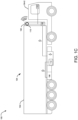
- the TRU 102 may be coupled to the front end (F) of the container/trailer 104-1 in the gap area between the cab 104-2 and container/trailer 104-1 as shown in FIGs. 1A and 1C , with the outlet port in fluidic communication with the storage space of the container/trailer and the inlet port in fluidic communication with the ambient or the storage space.
- the TRU 102 may be configured on top of the container 104-1 or cab 104-2 associated with the vehicle 104 as shown in FIG.
- the TRU 102 can be coupled to a prescribed position on a side or more than one side of the container/trailer 104-1.
- a plurality of TRUs can be coupled to a single container/trailer.
- a single TRU can be coupled to a plurality of containers/trailers.
- the bi-directional battery charging system 100 may include an existing battery management system 108 associated with the vehicle 104 or TRU 102.
- the battery 106 of the TRU 102 may be electrically coupled to the one or more components of the TRU 102 via the BMS 108.
- the BMS 108 may be configured to monitor the battery level of the TRU 102 and further control the charging of the battery 106 as well as the supply of electrical power from the battery 106 to the one or more components of the TRU 102 or vehicle 104.
- the TRU 102 may further include a controller 110 in communication with the battery 106, the BMS 108, and a vapor compression system/refrigeration circuit of the TRU 102.
- the controller 110 may be a control unit of the TRU 102. Further, in some embodiments, the controller 110 may be in communication with a control unit associated with the TRU 102 or the BMS 108. The controller 110 may be configured to control the vapor compression system or the refrigeration circuit and/or fans associated with the TRU 102 to adjust the cooling capacity of the TRU 102, based on products being transported and the real-time environment of the storage space, thereby maintaining a conditioned environment across the storage space.
- the bi-directional battery charging system 100 of the first TRU 102 may include a bi-directional charger 112 operatively connected to the controller 110 and the battery) 106 associated with the first TRU 102.
- the bi-directional charger 112 may be adapted to be electrically connected to an external electrical component selected from a group comprising an electrical grid 114 associated with one or more electrical power entities, a battery 120 associated with second TRU 118 associated with second vehicles 116, and a battery associated with non-TRU vehicles (not shown).
- the bi-directional charger 112 may enable the supply of electrical power from the external electrical component such as the electrical grid 114 associated with electrical power entities, battery 120 associated with the second TRU 118 (associated with the second vehicle 116), a battery associated with non-TRU vehicles or a combination thereof to the battery 106 associated with TRU 102, thereby enabling the charging of the battery 106 associated with TRU 102.
- the external electrical component such as the electrical grid 114 associated with electrical power entities, battery 120 associated with the second TRU 118 (associated with the second vehicle 116), a battery associated with non-TRU vehicles or a combination thereof to the battery 106 associated with TRU 102, thereby enabling the charging of the battery 106 associated with TRU 102.
- the bi-directional charger 112 may enable the supply of electrical power from the battery 106 associated with TRU 102 to the electrical grid 114, the battery 120 associated with the second TRU 118, the battery associated with non-TRU vehicles, and a combination thereof.
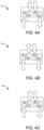
- the bi-directional charger 112 may include an AC to DC (ADC) converter that may be configured to convert AC electrical power received from the external electrical component (the electrical grid 114, the battery 120 of the second TRU 118, and the battery of the vehicle) into DC electrical power for the battery associated with the first TRU 106 when the bi-directional charger 112 of the TRU 102 is operating in the first mode.
- ADC AC to DC
- the bi-directional charger 112 may further include a DC to AC (DAC) converter that may be configured to convert DC electrical power supplied by the battery associated with the first TRU 106 into AC electrical power for the external electrical component (electrical grid 114, the battery 120 of second TRU 118, and the battery of the vehicle when the bi-directional charger 112 of the TRU 102 is operating in the second mode.
- DAC DC to AC
- the bi-directional charger 112 may include one or more AC to AC converters configured to convert AC electrical power having first electrical attributes being received from the external electrical component into AC electrical power having second electrical attributes for the battery associated with the first TRU 106 when the bi-directional charger 112 of the TRU 102 is operating in the first mode.
- the AC to AC converter may further convert AC electrical power having the second electrical attributes supplied by the battery associated with the first TRU 106 into AC electrical power having first electrical attributes for the external electrical component when the bi-directional charger 112 of the TRU 102 is operating in the second mode.
- the bi-directional charger 112 may include one or more DC to DC converters configured to convert DC electrical power having first electrical attributes being received from the external electrical component into DC electrical power having second electrical attributes for the battery associated with the first TRU 106 when the bi-directional charger 112 of the TRU 102 is operating in the first mode.
- the DC to DC converter may further convert DC electrical power having the second electrical attributes supplied by the battery associated with the first TRU 106 into DC electrical power having first electrical attributes for the external electrical component when the bi-directional charger 112 of the TRU 102 is operating in the second mode.
- the bi-directional charger 112 may be a power electronic device comprising power electronics semiconductor devices forming one or more of an inverter, a rectifier, a power converter, and the like to create one or more of the ADC converter, DAC converter, AC to AC converter, and DC to DC converter for the bi-directional charger 112.
- the bi-directional charger 112 may further include connection interfaces such as but not limited to connectors and cables that may physically and electrically connect the bi-directional charger 112 of the TRU 102 to the electrical grid 114, the second battery 120 of second TRUs 118, and battery of other non-TRU vehicles.
- the bi-directional charger 112 may further include fuses, circuit breakers, and other protective devices.
- the protective devices may include but are not limited to an over-charging protection module, an over-heating protection module, a surge protection module, an overcurrent protection module, and an over-voltage protection module.
- the BMS 108 may include a DAC converter configured to convert DC electrical power supplied through the bi-directional charger 112 into AC electrical power for one or more components of the TRU 102 and the battery associated with the first TRU 106. Further, in one or more embodiments, the BMS 108 may include an ADC converter to convert AC electrical power supplied through the bi-directional charger 112 into DC electrical power for one or more components of the TRU 102 and the battery associated with the first TRU 106.
- the BMS 108 and/or the bi-directional charger 112 may include one or more electrical sensors including a current sensor, voltage sensor, power sensor, and the like, to monitor the battery level of the battery associated with the first TRU 106 and also monitor the battery level of the second battery 120 and/or the third battery of the second TRUs 118 and/or the vehicle, respectively, when electrically connected to the bi-directional charger 112 of the TRU 102.
- one or more electrical sensors including a current sensor, voltage sensor, power sensor, and the like, to monitor the battery level of the battery associated with the first TRU 106 and also monitor the battery level of the second battery 120 and/or the third battery of the second TRUs 118 and/or the vehicle, respectively, when electrically connected to the bi-directional charger 112 of the TRU 102.
- the BMS 108 or the bi-directional charger 112 may be adapted to be communicatively coupled to a human-machine interface (HMI) device 122 (first HMI device) associated with a user (first user) of the TRU 102.
- the first HMI device 122 may enable the first user to monitor the battery level of the battery associated with the first TRU 106 and monitor the battery level of the second battery 120, and/or the third battery when electrically connected to the bi-directional charger 112 of the first TRU 102. Further, the first HMI device 122 may allow the first user to switch the bi-directional charger 112 between the first mode and the second mode.
- the system 200 may include a central server 202 and two or more TRUs 102-1 to 102-N (collectively referred to as TRU 102, herein) where each TRU 102 comprises a battery 106, a BMS 108, a controller 110, and a bi-directional charger 112 operatively connected to the BMS 108 and the controller 110 as explained in the above-mentioned paragraphs.
- the TRUs 102-1 to 102-N may be installed in containers/trailers 104-1 to 104-N (collectively referred to as containers or trailers 104, herein).
- the controller 110 associated with each of the TRUs 102 may be in communication with the server 202 via a network. Further, the bi-directional charger 112 associated with each of the TRUs 102 may be adapted to be electrically connected to the bi-directional charger 112 or the BMS 108 associated with the remaining TRUs. Furthermore, in one or more embodiments, the bi-directional charger 112 of the TRU 102 may be adapted to be electrically connected to an external electrical component selected from a group comprising an electrical grid 114 associated with one or more electrical power entities, and an external battery associated with other non-TRU equipped vehicles.
- the server 202 may be configured to operate the bi-directional charger 112 of the TRUs 102 in a first mode or a second mode.
- the bi-directional charger 112 of the TRU 102 may enable the battery 106 of the corresponding TRU 102 to receive electrical power from one or more of the electrical grid 114, the battery 106 associated with any of the remaining TRUs 102, and the external battery.
- the bi-directional charger 112 of the TRU 102 may enable the battery 106 of the corresponding TRU 102 to supply electrical power to one or more of the electrical grid 114, the battery 106 associated with any of the remaining TRUs 102, and the external battery. For instance, as shown in FIGs.
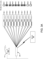
- the bi-directional charger 112 associated with any of the TRU 102-2, 102-5, 102-6 may be electrically connected to the battery 106 or bi-directional charger 112 of any of the TRU 102-1, 102-9. Accordingly, the TRU 102-2, 102-5, 102-6 may be operated in the first mode and the TRU 102-1, 102-9 may be operated in the second mode to enable the transfer of electrical power from the TRU 102-2, 102-5, 102-6 to TRU 102-1, 102-9.
- the bi-directional charger 112 associated with the TRUs 102 of the system 100 may be adapted to be operatively connected to one or more legacy TRUs that may include only a BMS and/or a unidirectional charger (without any bi-directional charger 112).
- the TRUs 102 having the bi-directional charger 112 may be configured to transfer electrical power from the battery 106 of the corresponding TRU 102 to the battery of the legacy TRUs, however, the TRUs 102 having the bi-directional charger 112 may not receive electrical power from the battery of the legacy TRUs.
- the non-TRU vehicles may include a unidirectional charger.
- the bi-directional charger 112 of the TRU 102 may be able to supply electrical power to the unidirectional charger or the external/third battery of the non-TRU vehicles, however, the unidirectional charger of the non-TRU vehicles may not be able to supply electrical power to the battery 106 of the TRUs 102.
- the non-TRU vehicles may also include a bi-directional charger.
- the bi-directional charger 112 of the TRU 102 may be configured to supply electrical power to the external/third battery of the non-TRU vehicles and the bi-directional charger of the non-TRU vehicles may also be configured to supply electrical power to the battery 106 of the TRUs 102.
- the BMS 108 of the TRUs 102 may be configured to monitor the battery level of the corresponding TRU 102 and transmit the monitored data to the server 202 in real-time. Further, in one or more embodiments, when the TRU 102 or containers 104 equipped with the TRU 102 are at a docking station with their battery 106 or the bi-directional charger 112 connected to a common charging station 204, the server 202 and the charging station 204 may enable the transfer of electrical power between the batteries of the TRUs 102, based on the battery level associated with each of the TRU 102, thereby creating a balance between the battery level of the TRUs 102 as shown in FIG. 3B .
- the common charging station 204 may be further electrically connected to the electric grid 114, which may allow the server 202 to enable the transfer of electrical power between each of the batteries of the TRUs 102 as well as between the batteries of the TRUs 102 and the electrical grid 114.
- the system 100 may further include one or more human-machine interface (HMI) devices 122 associated with users of the TRUs 102, the non-TRU vehicles, and the electrical power entities.
- HMI human-machine interface
- the HMI device 122 may be a mobile phone, a handheld device comprising an input device and a display device, a computing device comprising an input device and a display device, and a touchscreen-enabled computing device, but is not limited to the like.
- the HMI device 122, the controller 110 of the TRUs 102, the non-TRU vehicles, and the server 202 may include a communication module to communicatively couple the HMI device 122 to the controller 110 and BMS 108 of the TRU 102 and further communicatively couple the HMI device 122 to the server 202 via the network.
- the first HMI device 122 associated with the first users of the TRUs 102 may enable the first users to monitor the battery level of the battery associated with the first TRU 106 of their TRU 102 (first TRU 102) and further monitor the battery level of the second battery 120 associated with other TRUs 118 (second TRU 118) and/or the third battery of the vehicles when the second battery 120 or the third battery are electrically connected to the bi-directional charger 112 of the first TRU 102. Further, the first HMI device 122 may allow the first users to switch the bi-directional charger 112 of their first TRU 102 between the first mode and the second mode.
- the TRUs 102 having a battery level below a first level or operating in the first mode may be designated as a first set of TRUs 102. Further, the TRUs 102 having a battery level above the first level operating in the second mode may be designated as the second set of TRUs 102, herein. As illustrated in FIG. 3A , the TRUs 102-2 to 102-8 may be the second set of TRUs, and the TRUs 102-1, 102-9, and 102-N may be the first set of TRUs.
- the server 202 may enable the first users associated with the first set of TRUs 102-1, 102-9, and 102-N to transmit, using the first HMI device 122, a first set of signals to a second HMI device of second users associated with the second set of TRU 102-2 to 102-8.
- the first set of signals may be indicative of the location of the corresponding first TRU 102-1, 102-9, and 102-N and a request for supplying the electrical power from the battery 106-1, 106-9, 106-N of the corresponding first TRU 102-1, 102-9, and 102-N to the battery 106-2 to 106-8 of the corresponding second TRU 102-2 to 102-8.
- the server 202 may further enable the second users to transmit, using the second HMI device, a second set of signals to the first HMI device 122.
- the second set of signals may be indicative of the location of the corresponding second TRU 102-2 to 102-8 and confirmation for supplying the electrical power in response to the request. Accordingly, either the first user may bring the first TRU 102-1, 102-9, and 102-N to the location of any of the second users/second TRUs 102-2 to 102-8 to get the battery associated with the first TRU 106 charged, or the first user may request the second user to reach the location of the first users/first TRU 102-1, 102-9, and 102-N to charge the battery associated with the first TRU 106-1, 106-9, and 106-N.
- the server 202 may enable the first users associated with the first set of TRUs 102-1, 102-9, and 102-N to transmit, using the first HMI device 122, a third set of signals to one or more third HMI devices associated with the one or more electrical power entities and a third user associated with the one or more non-TRU vehicles.
- the third set of signals may be indicative of a request for supplying electrical power from the electrical grid 114 and/or the external battery of the non-TRU vehicles to the battery associated with the first TRU 106-1, 106-9, and 106-N of the TRUs 102-1, 102-9, and 102-N.
- the server 202 may further enable the electrical power entities and/or the third users associated with the vehicles to transmit, using third HMI devices, a fourth set of signals to the first HMI device 122 of the first TRU 102-1, 102-9, and 102-N.
- the third set of signals may be indicative of the location of the electrical grid 114 and/or the vehicle, and confirmation for supplying the electrical power in response to the request.
- the first user may bring the first TRU 102-1, 102-9, and 102-N to the electric grid 114 or the location of any of the third user/non-TRU vehicle to get the battery associated with the first TRU 106-1, 106-9, and 106-N charged, or the first user may request the third user to reach the location of the first user/first TRU 102-1, 102-9, and 102-N to charge the battery associated with the first TRU 106-1, 106-9, and 106-N
- this invention overcomes the drawbacks, and limitations associated with the existing battery-powered TRUs, by providing an improved, cost-effective, and efficient battery charging system for battery-powered TRUs, which enables the TRU to receive electrical power from an electrical grid as well as the battery associated with other TRUs and non-TRU vehicles.
- the invention further allows the TRU to resell or supply the electrical power (stored in the battery) to the electric grid and/or the battery associated with other TRUs and non-TRU vehicles.
Landscapes
- Engineering & Computer Science (AREA)
- Power Engineering (AREA)
- Mechanical Engineering (AREA)
- Transportation (AREA)
- Physics & Mathematics (AREA)
- Thermal Sciences (AREA)
- Health & Medical Sciences (AREA)
- Public Health (AREA)
- Charge And Discharge Circuits For Batteries Or The Like (AREA)
Abstract
A bi-directional battery charging system (100) for a first transport refrigeration unit (TRU) (102) is disclosed. The bi-directional battery charging system (100) comprises a bi-directional charger (112) operatively connected to a controller (110) and a battery (106) associated with the first TRU (102), wherein the bi-directional charger (112) is configured to be electrically connected to an external electrical component selected from the group of an electrical grid (114), a battery (120) associated with second TRUs (118), and a battery associated with vehicles.
Description
- This patent application claims the benefit of
US Provisional Patent Application No. 63/508,689, filed on Jun 16, 2023 - This invention relates to transport refrigeration units and battery management systems.
- Transport refrigeration units (TRUs) may be used to conserve and maintain the temperature of perishable goods during transportation. Battery-powered TRUs may generally be employed for storing and transporting perishable goods while restricting emissions and lowering environmental impact. However, the battery associated with a battery-powered TRU may run low, which may affect the stored goods. Moreover, the charging system of existing battery-powered TRU may allow the battery to recharge only through an external power supply which may not be available at all places.
- According to a first aspect of the invention there is provideda first transport refrigeration unit (TRU) comprising a bi-directional battery charging system. The bi-directional battery charging system comprises a bi-directional charger operatively connected to a controller and a battery associated with the first TRU, wherein the bi-directional charger is configured to be electrically connected to an external electrical component selected from the group consisting of an electrical grid, a battery associated with a second TRU, a battery associated with a vehicle, and combinations thereof.
- According to a second aspect of the invention there is provided a bi-directional battery charging system for a first transport refrigeration unit (TRU), the bi-directional battery charging system comprising: a bi-directional charger operatively connected to a controller and a battery associated with the first TRU, wherein the bi-directional charger is configured to be electrically connected to an external electrical component selected from the group of an electrical grid, a battery associated with a second TRU, a battery associated with vehicles, and a combination thereof.
- Optionally, in a first mode, the bi-directional charger enables supply of electrical power from the external electrical component to the battery associated with the first TRU.
- Optionally, in a second mode, the bi-directional charger enables supply of electrical power from the battery associated with the first TRU to the external electrical component.
- Optionally, the bi-directional charger comprises an AC to DC (ADC) converter configured to convert AC electrical power received from the external electrical component into DC electrical power for the battery associated with the first TRU, and a DC to AC (DAC) converter configured to convert DC electrical power supplied by the battery associated with the first TRU into AC electrical power for the external electrical component.
- Optionally, the bi-directional charger comprises one or more AC to AC converters configured to convert AC electrical power having first electrical attributes received from the external electrical component into AC electrical power having second electrical attributes for the battery associated with the first TRU, and convert AC electrical power having the second electrical attributes supplied by the battery associated with the first TRU into AC electrical power having first electrical attributes for the external electrical component.
- Optionally, the bi-directional charger comprises one or more DC to DC converters configured to convert DC electrical power having first electrical attributes being received from the external electrical component into DC electrical power having second electrical attributes for the battery associated with the first TRU, and convert DC electrical power having the second electrical attributes supplied by the battery associated with the first TRU into DC electrical power having first electrical attributes for the external electrical component.
- Optionally, the bi-directional battery charging system comprises a battery management system (BMS) associated with the TRU, wherein the BMS comprises a DAC converter configured to convert DC electrical power supplied by the bi-directional charger into AC electrical power for one or more components of the first TRU and the battery associated with the first TRU.
- Optionally, the BMS comprises an ADC converter to convert AC electrical power supplied by the bi-directional charger into DC electrical power for one or more components of the TRU and the battery associated with the first TRU.
- In one or more embodiments, the BMS comprises one or more sensors to: monitor a battery level of the battery associated with the first TRU; monitor a battery level of a battery associated with the external electrical component when electrically connected to the bi-directional charger of the TRU; or monitor both battery levels.
- Optionally, the BMS of the TRU is communicatively coupled to a first human-machine interface (HMI) device associated with a user of the first TRU, wherein the first HMI device enables the user of the first TRU to: monitor the battery level of the battery associated with the first TRU: monitor a battery level of a battery associated with the external electrical component when electrically connected to the bi-directional charger of the TRU; and switch the bi-directional charger between the first mode and the second mode.
- Optionally, the first HMI device enables the user of the first TRU (the first user) to transmit to a second HMI device associated with a user of the external electrical component (the second user), a first set of signals pertaining to a request for supplying electrical power from the external electrical component to the battery associated with the first TRU, and/or receive, from the second HMI device, a second set of signals pertaining to a request for supplying electrical power from the battery associated with the first TRU to the external electrical component.
- According to a third aspect of the invention there is provided a system for enabling bi-directional charging in two or more transport refrigeration units (TRUs). The system comprises a server, and two or more TRUs, each comprising a battery, a controller, and a bi-directional charger operatively connected to the battery and the controller, wherein the controller associated with each of the two or more TRUs is in communication with the server, wherein the bi-directional charger associated with each of the two or more TRUs is configured to be electrically connected to the bi-directional charger associated with remaining TRUs.
- Optionally, the bi-directional charger of each of the two or more TRUs is configured to be electrically connected to an external electrical component selected from the group consisting of an electrical grid, a battery associated with a vehicle, and a combination thereof.
- Optionally, the server is configured to operate the bi-directional charger of the two or more TRUs in a first mode, wherein the bi-directional charger enables the battery of the corresponding TRU to receive electrical power from the external electrical component, the battery associated with any of the remaining TRUs, or both.
- Optionally, the server is configured to operate the bi-directional charger of the two or more TRUs in a second mode, wherein the bi-directional charger enables the battery of the corresponding TRU to supply electrical power to the external electrical component, the battery associated with any of the remaining TRUs, or both.
- Optionally, the server is in communication with a battery management system of the TRU and configured to monitor a battery level associated with each of the two or more TRUs, wherein the server enables the transfer of electrical power between the two or more TRUs at a charging station, based on the battery level associated with each of the one or more TRUs.
- Optionally, the server enables a first HMI device associated with a user of a first set of TRUs among the two or more TRUs having a battery level above a first level to transmit, to a second HMI device of a user associated with a second set of TRUs among the two or more TRUs having a battery level below the first level, a first set of signals pertaining to a location of the corresponding first TRU, and a request for supplying the electrical power from the battery of the corresponding first TRU to the battery of the corresponding second TRU.
- Optionally, the server enables the second HMI device associated with the second set of TRUs, to transmit a second set of signals pertaining to a location of the corresponding second TRU, and a confirmation for supplying the electrical power in response to the request.
- Optionally, the server enables the first HMI device associated with the first set of TRUs to transmit, to one or more third HMI devices associated with the external electrical component, a third set of signals pertaining to a request for supplying electrical power from the external electrical component to the battery associated with the first set of TRUs, and/or receive, from the one or more third HMI devices, a fourth set of signals pertaining to a location of the external electrical component and a confirmation for supplying the electrical power in response to the request.
- The foregoing summary is illustrative only and is not intended to be in any way limiting. In addition to the illustrative aspects, embodiments, and features described above, further aspects, embodiments, features, and techniques of the invention will become more apparent from the following description taken in conjunction with the drawings.
- The accompanying drawings are included to provide a further understanding of the invention by way of example only and are incorporated in and constitute a part of this specification. The drawings illustrate exemplary embodiments of the invention and, together with the description, serve to explain the principles of the invention.
- In the drawings, similar components and/or features may have the same reference label. Further, various components of the same type may be distinguished by following the reference label with a second label that distinguishes among the similar components. If only the first reference label is used in the specification, the description is applicable to any one of the similar components having the same first reference label irrespective of the second reference label.
-
FIGs. 1A to 1C show a bi-directional charging system implemented in a transport refrigeration unit (TRU) associated with a cargo truck or vehicle. -
FIGs. 2 ,3A , and3B show the network architecture of a system for enabling bi-directional charging between one or more TRUs and an electric grid. -
FIGs. 4A to 4C show a block diagram of one or more bi-directional charger associated with the bi-directional charging system. - The following is a detailed description of embodiments of the invention depicted in the accompanying drawings. The embodiments are in such detail as to clearly communicate the invention. However, the amount of detail offered is not intended to limit the anticipated variations of embodiments; on the contrary, the intention is to cover all modifications and alternatives falling within the scope of the invention as set out in the appended claims.
- Various terms are used herein. To the extent a term used in a claim is not defined below, it should be given the broadest definition persons in the pertinent art have given that term as reflected in printed publications and issued patents at the time of filing.
- In the specification, reference may be made to the spatial relationships between various components and to the spatial orientation of various aspects of components as the devices are depicted in the attached drawings. However, as will be recognized by those skilled in the art after a complete reading of the disclosure, the components described herein may be positioned in any desired orientation. Thus, the use of terms such as "above," "below," "upper," "lower," "first", "second" or other like terms to describe a spatial relationship between various components or to describe the spatial orientation of aspects of such components should be understood to describe a relative relationship between the components or a spatial orientation of aspects of such components.
- Trailer refrigeration units (TRUs) may be employed with containers or trailers to supply conditioned air within the corresponding container for maintaining a conditioned environment inside the storage space of the container. Various goods including but not limited to pharmaceutical and nutraceutical products, and perishable items such as foods and beverages may be stored and transported in the containers equipped with the TRU. Battery-powered TRUs may be employed for conserving and transporting goods, lowering emissions and the environmental impact that may be caused by diesel-powered TRUs, and the like. However, the battery associated with battery-powered TRU may run low, which may affect the stored goods. Moreover, the charging system of existing battery-powered TRU may allow the battery to recharge only through an external power source that may not be available at all places. Accordingly, there is a need to provide a system for more versatile charging option for the battery of a TRU.
- This invention addresses the aforementioned needs of battery-powered TRUs, by providing an improved, cost-effective, and efficient battery charging system for battery-powered TRUs, which enables the TRU to receive electrical power from an electrical grid as well as from a battery associated with other TRUs and non-TRU equipped vehicles. Additionally, the battery charging system further allows the TRU to resell or supply the electrical power (stored in the battery) to the electric grid, and/or to a battery associated with other TRUs and non-TRU vehicles.
- Referring to
FIGs. 1A to 2 , a bi-directionalbattery charging system 100 for a battery-powered transport refrigeration unit (TRU) 102 (also referred to as first TRU, herein) is disclosed. The TRU 102 may be installed on a container or trailer 104-1 associated with avehicle 104. The TRU 102 may include abattery 106 to operate/run the TRU 102 for maintaining a conditioned environment in an enclosed (storage or conservation) space within the container/trailer 104-1. Various products including but not limited to pharmaceutical and nutraceutical products, and perishable items such as foods and beverages, and the like may be stored and transported in the container/trailer 104-1. TheTRU 102 may maintain the environment of the storage space at a specific or user-defined temperature and/or humidity, based on the stored products, to keep the stored products in a desired condition while transporting and comply with product compliance regulations. - The
TRU 102 may be installed on the container/trailer 104 associated with one ormore vehicles 104 including but not limited to an electric truck, a semi-electric truck, and a non-electric truck such that theTRU 102 remains fluidically connected to the ambient and further remains fluidically connected to the storage space of the container/trailer 104-1. However, theTRU 102 of thevehicles 104 may be battery-powered, which may receive electrical power from thebattery 106. Accordingly, based on the environment to be maintained in the storage space or based on the products to be transported, theTRU 102 may be operated to adjust its cooling capacity and supply conditioned air within the storage space. - In one or more embodiments, the container/trailer 104-1 may be coupled to a rear end of a cab or truck 104-2 associated with the cargo truck/
vehicle 104 such that a gap remains therebetween. TheTRU 102 may be coupled to the front end (F) of the container/trailer 104-1 in the gap area between the cab 104-2 and container/trailer 104-1 as shown inFIGs. 1A and1C , with the outlet port in fluidic communication with the storage space of the container/trailer and the inlet port in fluidic communication with the ambient or the storage space. In some embodiments, theTRU 102 may be configured on top of the container 104-1 or cab 104-2 associated with thevehicle 104 as shown inFIG. 1B such that the outlet port ofTRU 102 remains in fluidic communication with the storage space of the container/trailer 104-1 and the inlet port in fluidic communication with the ambient or the storage space. Alternatively, (not shown) theTRU 102 can be coupled to a prescribed position on a side or more than one side of the container/trailer 104-1. Moreover, (not shown) a plurality of TRUs can be coupled to a single container/trailer. Alternatively, a single TRU can be coupled to a plurality of containers/trailers. - In one or more embodiments, the bi-directional
battery charging system 100 may include an existingbattery management system 108 associated with thevehicle 104 orTRU 102. Thebattery 106 of theTRU 102 may be electrically coupled to the one or more components of theTRU 102 via theBMS 108. TheBMS 108 may be configured to monitor the battery level of theTRU 102 and further control the charging of thebattery 106 as well as the supply of electrical power from thebattery 106 to the one or more components of theTRU 102 orvehicle 104. TheTRU 102 may further include acontroller 110 in communication with thebattery 106, theBMS 108, and a vapor compression system/refrigeration circuit of theTRU 102. - In one or more embodiments, the
controller 110 may be a control unit of theTRU 102. Further, in some embodiments, thecontroller 110 may be in communication with a control unit associated with theTRU 102 or theBMS 108. Thecontroller 110 may be configured to control the vapor compression system or the refrigeration circuit and/or fans associated with theTRU 102 to adjust the cooling capacity of theTRU 102, based on products being transported and the real-time environment of the storage space, thereby maintaining a conditioned environment across the storage space. - The bi-directional
battery charging system 100 of thefirst TRU 102 may include abi-directional charger 112 operatively connected to thecontroller 110 and the battery) 106 associated with thefirst TRU 102. Thebi-directional charger 112 may be adapted to be electrically connected to an external electrical component selected from a group comprising anelectrical grid 114 associated with one or more electrical power entities, abattery 120 associated withsecond TRU 118 associated withsecond vehicles 116, and a battery associated with non-TRU vehicles (not shown). - In one or more embodiments, in a first (charging) mode, the
bi-directional charger 112 may enable the supply of electrical power from the external electrical component such as theelectrical grid 114 associated with electrical power entities,battery 120 associated with the second TRU 118 (associated with the second vehicle 116), a battery associated with non-TRU vehicles or a combination thereof to thebattery 106 associated withTRU 102, thereby enabling the charging of thebattery 106 associated withTRU 102. Further, in one or more embodiments, in a second (energy reselling) mode, thebi-directional charger 112 may enable the supply of electrical power from thebattery 106 associated withTRU 102 to theelectrical grid 114, thebattery 120 associated with thesecond TRU 118, the battery associated with non-TRU vehicles, and a combination thereof. - In one or more embodiments, referring to
FIG. 4A , thebi-directional charger 112 may include an AC to DC (ADC) converter that may be configured to convert AC electrical power received from the external electrical component (theelectrical grid 114, thebattery 120 of thesecond TRU 118, and the battery of the vehicle) into DC electrical power for the battery associated with thefirst TRU 106 when thebi-directional charger 112 of theTRU 102 is operating in the first mode. Thebi-directional charger 112 may further include a DC to AC (DAC) converter that may be configured to convert DC electrical power supplied by the battery associated with thefirst TRU 106 into AC electrical power for the external electrical component (electrical grid 114, thebattery 120 ofsecond TRU 118, and the battery of the vehicle when thebi-directional charger 112 of theTRU 102 is operating in the second mode. - In one or more embodiments, referring to
FIG. 4B , thebi-directional charger 112 may include one or more AC to AC converters configured to convert AC electrical power having first electrical attributes being received from the external electrical component into AC electrical power having second electrical attributes for the battery associated with thefirst TRU 106 when thebi-directional charger 112 of theTRU 102 is operating in the first mode. The AC to AC converter may further convert AC electrical power having the second electrical attributes supplied by the battery associated with thefirst TRU 106 into AC electrical power having first electrical attributes for the external electrical component when thebi-directional charger 112 of theTRU 102 is operating in the second mode. - In one or more embodiments, referring to
FIG. 4C , thebi-directional charger 112 may include one or more DC to DC converters configured to convert DC electrical power having first electrical attributes being received from the external electrical component into DC electrical power having second electrical attributes for the battery associated with thefirst TRU 106 when thebi-directional charger 112 of theTRU 102 is operating in the first mode. The DC to DC converter may further convert DC electrical power having the second electrical attributes supplied by the battery associated with thefirst TRU 106 into DC electrical power having first electrical attributes for the external electrical component when thebi-directional charger 112 of theTRU 102 is operating in the second mode. - In one or more embodiments, the
bi-directional charger 112 may be a power electronic device comprising power electronics semiconductor devices forming one or more of an inverter, a rectifier, a power converter, and the like to create one or more of the ADC converter, DAC converter, AC to AC converter, and DC to DC converter for thebi-directional charger 112. Thebi-directional charger 112 may further include connection interfaces such as but not limited to connectors and cables that may physically and electrically connect thebi-directional charger 112 of theTRU 102 to theelectrical grid 114, thesecond battery 120 ofsecond TRUs 118, and battery of other non-TRU vehicles. Thebi-directional charger 112 may further include fuses, circuit breakers, and other protective devices. In one or more embodiments, the protective devices may include but are not limited to an over-charging protection module, an over-heating protection module, a surge protection module, an overcurrent protection module, and an over-voltage protection module. - In one or more embodiments, the
BMS 108 may include a DAC converter configured to convert DC electrical power supplied through thebi-directional charger 112 into AC electrical power for one or more components of theTRU 102 and the battery associated with thefirst TRU 106. Further, in one or more embodiments, theBMS 108 may include an ADC converter to convert AC electrical power supplied through thebi-directional charger 112 into DC electrical power for one or more components of theTRU 102 and the battery associated with thefirst TRU 106. - In one or more embodiments, the
BMS 108 and/or thebi-directional charger 112 may include one or more electrical sensors including a current sensor, voltage sensor, power sensor, and the like, to monitor the battery level of the battery associated with thefirst TRU 106 and also monitor the battery level of thesecond battery 120 and/or the third battery of thesecond TRUs 118 and/or the vehicle, respectively, when electrically connected to thebi-directional charger 112 of theTRU 102. - The
BMS 108 or thebi-directional charger 112 may be adapted to be communicatively coupled to a human-machine interface (HMI) device 122 (first HMI device) associated with a user (first user) of theTRU 102. Thefirst HMI device 122 may enable the first user to monitor the battery level of the battery associated with thefirst TRU 106 and monitor the battery level of thesecond battery 120, and/or the third battery when electrically connected to thebi-directional charger 112 of thefirst TRU 102. Further, thefirst HMI device 122 may allow the first user to switch thebi-directional charger 112 between the first mode and the second mode. - Referring to
FIGs. 2 to 3B , asystem 200 for enabling bi-directional charging in two or more transport refrigeration units is disclosed. Thesystem 200 may include acentral server 202 and two or more TRUs 102-1 to 102-N (collectively referred to asTRU 102, herein) where eachTRU 102 comprises abattery 106, aBMS 108, acontroller 110, and abi-directional charger 112 operatively connected to theBMS 108 and thecontroller 110 as explained in the above-mentioned paragraphs. The TRUs 102-1 to 102-N may be installed in containers/trailers 104-1 to 104-N (collectively referred to as containers ortrailers 104, herein). Thecontroller 110 associated with each of theTRUs 102 may be in communication with theserver 202 via a network. Further, thebi-directional charger 112 associated with each of theTRUs 102 may be adapted to be electrically connected to thebi-directional charger 112 or theBMS 108 associated with the remaining TRUs. Furthermore, in one or more embodiments, thebi-directional charger 112 of theTRU 102 may be adapted to be electrically connected to an external electrical component selected from a group comprising anelectrical grid 114 associated with one or more electrical power entities, and an external battery associated with other non-TRU equipped vehicles. - The
server 202 may be configured to operate thebi-directional charger 112 of theTRUs 102 in a first mode or a second mode. In the first mode, thebi-directional charger 112 of theTRU 102 may enable thebattery 106 of thecorresponding TRU 102 to receive electrical power from one or more of theelectrical grid 114, thebattery 106 associated with any of the remainingTRUs 102, and the external battery. Further, in the second mode, thebi-directional charger 112 of theTRU 102 may enable thebattery 106 of thecorresponding TRU 102 to supply electrical power to one or more of theelectrical grid 114, thebattery 106 associated with any of the remainingTRUs 102, and the external battery. For instance, as shown inFIGs. 3A and3B , thebi-directional charger 112 associated with any of the TRU 102-2, 102-5, 102-6 may be electrically connected to thebattery 106 orbi-directional charger 112 of any of the TRU 102-1, 102-9. Accordingly, the TRU 102-2, 102-5, 102-6 may be operated in the first mode and the TRU 102-1, 102-9 may be operated in the second mode to enable the transfer of electrical power from the TRU 102-2, 102-5, 102-6 to TRU 102-1, 102-9. - In one or more embodiments, the
bi-directional charger 112 associated with theTRUs 102 of thesystem 100 may be adapted to be operatively connected to one or more legacy TRUs that may include only a BMS and/or a unidirectional charger (without any bi-directional charger 112). In such embodiments, theTRUs 102 having thebi-directional charger 112 may be configured to transfer electrical power from thebattery 106 of thecorresponding TRU 102 to the battery of the legacy TRUs, however, theTRUs 102 having thebi-directional charger 112 may not receive electrical power from the battery of the legacy TRUs. - In one or more embodiments, the non-TRU vehicles (having the external/third battery) may include a unidirectional charger. In such embodiments, the
bi-directional charger 112 of theTRU 102 may be able to supply electrical power to the unidirectional charger or the external/third battery of the non-TRU vehicles, however, the unidirectional charger of the non-TRU vehicles may not be able to supply electrical power to thebattery 106 of theTRUs 102. However, in one or more embodiments, the non-TRU vehicles (having the external/third battery) may also include a bi-directional charger. In such embodiments, thebi-directional charger 112 of theTRU 102 may be configured to supply electrical power to the external/third battery of the non-TRU vehicles and the bi-directional charger of the non-TRU vehicles may also be configured to supply electrical power to thebattery 106 of theTRUs 102. - In one or more embodiments, the
BMS 108 of theTRUs 102 may be configured to monitor the battery level of thecorresponding TRU 102 and transmit the monitored data to theserver 202 in real-time. Further, in one or more embodiments, when theTRU 102 orcontainers 104 equipped with theTRU 102 are at a docking station with theirbattery 106 or thebi-directional charger 112 connected to acommon charging station 204, theserver 202 and the chargingstation 204 may enable the transfer of electrical power between the batteries of theTRUs 102, based on the battery level associated with each of theTRU 102, thereby creating a balance between the battery level of theTRUs 102 as shown inFIG. 3B . In addition, in one or more embodiments, thecommon charging station 204 may be further electrically connected to theelectric grid 114, which may allow theserver 202 to enable the transfer of electrical power between each of the batteries of theTRUs 102 as well as between the batteries of theTRUs 102 and theelectrical grid 114. - The
system 100 may further include one or more human-machine interface (HMI)devices 122 associated with users of theTRUs 102, the non-TRU vehicles, and the electrical power entities. In one or more embodiments, theHMI device 122 may be a mobile phone, a handheld device comprising an input device and a display device, a computing device comprising an input device and a display device, and a touchscreen-enabled computing device, but is not limited to the like. TheHMI device 122, thecontroller 110 of theTRUs 102, the non-TRU vehicles, and theserver 202 may include a communication module to communicatively couple theHMI device 122 to thecontroller 110 andBMS 108 of theTRU 102 and further communicatively couple theHMI device 122 to theserver 202 via the network. - In one or more embodiments, the
first HMI device 122 associated with the first users of theTRUs 102 may enable the first users to monitor the battery level of the battery associated with thefirst TRU 106 of their TRU 102 (first TRU 102) and further monitor the battery level of thesecond battery 120 associated with other TRUs 118 (second TRU 118) and/or the third battery of the vehicles when thesecond battery 120 or the third battery are electrically connected to thebi-directional charger 112 of thefirst TRU 102. Further, thefirst HMI device 122 may allow the first users to switch thebi-directional charger 112 of theirfirst TRU 102 between the first mode and the second mode. TheTRUs 102 having a battery level below a first level or operating in the first mode may be designated as a first set ofTRUs 102. Further, theTRUs 102 having a battery level above the first level operating in the second mode may be designated as the second set ofTRUs 102, herein. As illustrated inFIG. 3A , the TRUs 102-2 to 102-8 may be the second set of TRUs, and the TRUs 102-1, 102-9, and 102-N may be the first set of TRUs. - In one or more embodiments, the
server 202 may enable the first users associated with the first set of TRUs 102-1, 102-9, and 102-N to transmit, using thefirst HMI device 122, a first set of signals to a second HMI device of second users associated with the second set of TRU 102-2 to 102-8. The first set of signals may be indicative of the location of the corresponding first TRU 102-1, 102-9, and 102-N and a request for supplying the electrical power from the battery 106-1, 106-9, 106-N of the corresponding first TRU 102-1, 102-9, and 102-N to the battery 106-2 to 106-8 of the corresponding second TRU 102-2 to 102-8. Theserver 202 may further enable the second users to transmit, using the second HMI device, a second set of signals to thefirst HMI device 122. The second set of signals may be indicative of the location of the corresponding second TRU 102-2 to 102-8 and confirmation for supplying the electrical power in response to the request. Accordingly, either the first user may bring the first TRU 102-1, 102-9, and 102-N to the location of any of the second users/second TRUs 102-2 to 102-8 to get the battery associated with thefirst TRU 106 charged, or the first user may request the second user to reach the location of the first users/first TRU 102-1, 102-9, and 102-N to charge the battery associated with the first TRU 106-1, 106-9, and 106-N. - In one or more embodiments, the
server 202 may enable the first users associated with the first set of TRUs 102-1, 102-9, and 102-N to transmit, using thefirst HMI device 122, a third set of signals to one or more third HMI devices associated with the one or more electrical power entities and a third user associated with the one or more non-TRU vehicles. The third set of signals may be indicative of a request for supplying electrical power from theelectrical grid 114 and/or the external battery of the non-TRU vehicles to the battery associated with the first TRU 106-1, 106-9, and 106-N of the TRUs 102-1, 102-9, and 102-N. Theserver 202 may further enable the electrical power entities and/or the third users associated with the vehicles to transmit, using third HMI devices, a fourth set of signals to thefirst HMI device 122 of the first TRU 102-1, 102-9, and 102-N. The third set of signals may be indicative of the location of theelectrical grid 114 and/or the vehicle, and confirmation for supplying the electrical power in response to the request. Accordingly, either the first user may bring the first TRU 102-1, 102-9, and 102-N to theelectric grid 114 or the location of any of the third user/non-TRU vehicle to get the battery associated with the first TRU 106-1, 106-9, and 106-N charged, or the first user may request the third user to reach the location of the first user/first TRU 102-1, 102-9, and 102-N to charge the battery associated with the first TRU 106-1, 106-9, and 106-N - Thus, this invention overcomes the drawbacks, and limitations associated with the existing battery-powered TRUs, by providing an improved, cost-effective, and efficient battery charging system for battery-powered TRUs, which enables the TRU to receive electrical power from an electrical grid as well as the battery associated with other TRUs and non-TRU vehicles. The invention further allows the TRU to resell or supply the electrical power (stored in the battery) to the electric grid and/or the battery associated with other TRUs and non-TRU vehicles.
- While the invention has been described with reference to exemplary embodiments, it will be understood by those skilled in the art that various changes may be made without departing from the scope of the invention as set out in the appended claims. Modifications may be made to adopt a particular situation or material to the teachings of the inveniton without departing from the scope thereof. Therefore, it is intended that the invention not be limited to the particular embodiment disclosed, but that the invention includes all embodiments falling within the scope of the invention as set out in the appended claims.
- In interpreting the specification, all terms should be interpreted in the broadest possible manner consistent with the context. In particular, the terms "comprises" and "comprising" should be interpreted as referring to elements, components, or steps in a non-exclusive manner, indicating that the referenced elements, components, or steps may be present, or utilized, or combined with other elements, components, or steps that are not expressly referenced. Where the specification claims refer to at least one of something selected from the group consisting of A, B, C ....and N, the text should be interpreted as requiring only one element from the group, not A plus N, or B plus N, etc.
Claims (15)
- A bi-directional battery charging system (100) for a first transport refrigeration unit (TRU) (102), the bi-directional battery charging system comprising:a bi-directional charger (112) operatively connected to a controller (110) and a battery (106) associated with the first TRU,wherein the bi-directional charger is configured to be electrically connected to an external electrical component selected from the group of an electrical grid (114), a battery (120) associated with a second TRU (118), a battery associated with vehicles, and a combination thereof.
- The bi-directional battery charging system (100) of claim 1, wherein, in a first mode, the bi-directional charger (112) enables supply of electrical power from the external electrical component to the battery (106) associated with the first TRU (102); and/or
wherein, in a second mode, the bi-directional charger (112) enables supply of electrical power from the battery (106) associated with the first TRU (102) to the external electrical component. - The bi-directional battery charging system (100) of any of claims 1 and 2, wherein the bi-directional charger (112) comprises:an AC to DC (ADC) converter configured to convert AC electrical power received from the external electrical component into DC electrical power for the battery (106) associated with the first TRU (102); anda DC to AC (DAC) converter configured to convert DC electrical power supplied by the battery associated with the first TRU into AC electrical power for the external electrical component.
- The bi-directional battery charging system (100) of any preceding claim, wherein the bi-directional charger (112) comprises one or more AC to AC converters configured to:convert AC electrical power having first electrical attributes being received from the external electrical component into AC electrical power having second electrical attributes for the battery (106) associated with the first TRU (102); andconvert AC electrical power having the second electrical attributes supplied by the battery associated with the first TRU into AC electrical power having first electrical attributes for the external electrical component.
- The bi-directional battery charging system (100) of any preceding claim, wherein the bi-directional charger (112) comprises one or more DC to DC converters configured to:convert DC electrical power having first electrical attributes being received from the external electrical component into DC electrical power having second electrical attributes for the battery (106) associated with the first TRU (102); andconvert DC electrical power having the second electrical attributes supplied by the battery associated with the first TRU into DC electrical power having first electrical attributes for the external electrical component.
- The bi-directional battery charging system (100) of any preceding claim, wherein the bi-directional battery charging system comprises a battery management system BMS (108) associated with the TRU (102), wherein the BMS comprises a DAC converter configured to convert DC electrical power supplied by the bi-directional charger (112) into AC electrical power for one or more components of the first TRU and the battery (106) associated with the first TRU.
- The bi-directional battery charging system (100) of claim 6, wherein the BMS (108) comprises an ADC converter to convert AC electrical power supplied by the bi-directional charger (112) into DC electrical power for one or more components of the TRU (102) and the battery (106) associated with the first TRU; and/or
wherein the BMS (108) comprises one or more sensors to:monitor a battery level of the battery associated with the first TRU (102); andmonitor a battery level of the battery associated with the external electrical component when electrically connected to the bi-directional charger (112) of the TRU. - The bi-directional battery charging system (100) of any of claims 6 and 7, wherein the BMS (108) of the TRU (102) is communicatively coupled to a first human-machine interface HMI device (122) associated with a user of the first TRU, wherein the first HMI device enables the user of the first TRU to:
monitor the battery level of the battery (106) associated with the first TRU:monitor the battery level of the external electrical component; andswitch the bi-directional charger (112) between the first mode and the second mode. - The bi-directional battery charging system (100) of claim 8, wherein the first HMI device (122) enables the user of the first TRU (102) to:transmit, to a second HMI device associated with a user of the external electrical component, a first set of signals pertaining to a request for supplying electrical power from the external electrical component to the battery associated with the first TRU; and/orreceive, from the second HMI device, a second set of signals pertaining to a request for supplying electrical power from the battery associated with the first TRU to the external electrical component.
- A system (200) for enabling bi-directional charging in two or more transport refrigeration units TRUs (102), the system comprising:a server (202); andtwo or more TRUs, each comprising a battery (106), a controller (110), and a bi-directional charger (112) operatively connected to the battery and the controller, wherein the controller associated with each of the two or more TRUs is in communication with the server,wherein the bi-directional charger associated with each of the two or more TRUs is configured to be electrically connected to the bi-directional charger associated with the remaining TRUs.
- The system (200) of claim 10, wherein the bi-directional charger (112) of each of the two or more TRUs (102) is configured to be electrically connected to an external electrical component selected from an electrical grid (114), a battery (106) associated with a vehicle, and a combination thereof.
- The system (200) of any of claims 10 and 11, wherein the server (202) is configured to operate the bi-directional charger (112) of the two or more TRUs (102) in a first mode, wherein the bi-directional charger enables the battery (106) of the corresponding TRU to receive electrical power from the external electrical component, the battery associated with any of the remaining TRUs, or both; and/or
wherein the server (202) is configured to operate the bi-directional charger (112) of the two or more TRUs (102) in a second mode, wherein the bi-directional charger enables the battery (106) of the corresponding TRU to supply electrical power to the external electrical component, the battery associated with any of the remaining TRUs, or both. - The system (200) of any of claims 10 to 12, wherein the server (202) is in communication with a battery management system (108) of the TRU (102) and configured to monitor battery level associated with each of the two or more TRUs,
wherein the server enables the transfer of electrical power between the two or more TRUs at a charging station (204), based on the battery level associated with each of the two or more TRUs. - The system (200) of any of claims 10 to 13, wherein the server (202) enables a first HMI device (122) associated with a user of a first set of TRUs (102) among the two or more TRUs having the battery level above a first level to:transmit, to a second HMI device of a user associated with a second set of TRUs among the two or more TRUs having the battery level below the first level, a first set of signals pertaining to a location of the corresponding first TRU, and a request for supplying the electrical power from the battery of the corresponding first TRU to the battery of the corresponding second TRU,optionally wherein the server (202) enables the second HMI device associated with the second set of TRUs, to transmit a second set of signals pertaining to a location of the corresponding second TRU, and a confirmation for supplying the electrical power in response to the request.
- The system (200) of claim 14, wherein the server (202) enables the first HMI device (122) associated with the first set of TRUs (102) to:transmit, to one or more third HMI devices associated with the external electrical component, a third set of signals pertaining to a request for supplying electrical power from the external electrical component to the battery (106) associated with the first TRU; and/orreceive, from the one or more third HMI devices, a fourth set of signals pertaining to a location of the external electrical component and a confirmation for supplying the electrical power in response to the request.
Applications Claiming Priority (1)
| Application Number | Priority Date | Filing Date | Title |
|---|---|---|---|
| US202363508689P | 2023-06-16 | 2023-06-16 |
Publications (1)
| Publication Number | Publication Date |
|---|---|
| EP4481976A1 true EP4481976A1 (en) | 2024-12-25 |
Family
ID=91580882
Family Applications (1)
| Application Number | Title | Priority Date | Filing Date |
|---|---|---|---|
| EP24182228.7A Pending EP4481976A1 (en) | 2023-06-16 | 2024-06-14 | Bi-directional battery charging system for one or more transport refrigeration unit |
Country Status (3)
| Country | Link |
|---|---|
| US (1) | US20240421627A1 (en) |
| EP (1) | EP4481976A1 (en) |
| CN (1) | CN119154467A (en) |
Citations (3)
| Publication number | Priority date | Publication date | Assignee | Title |
|---|---|---|---|---|
| US10723295B2 (en) * | 2018-03-15 | 2020-07-28 | Thermo King Corporation | Methods and systems for managing bi-directional converter based battery modules |
| US20220169139A1 (en) * | 2020-11-30 | 2022-06-02 | Wobben Properties Gmbh | Method for controlling an exchange power between a charging infrastructure and an electrical supply network |
| US20230025134A1 (en) * | 2021-07-23 | 2023-01-26 | Hyundai Motor Company | Apparatus and Method for Controlling Bidirectional On Board Charger of Electric Vehicle |
-
2024
- 2024-06-04 US US18/732,965 patent/US20240421627A1/en active Pending
- 2024-06-14 CN CN202410765266.9A patent/CN119154467A/en active Pending
- 2024-06-14 EP EP24182228.7A patent/EP4481976A1/en active Pending
Patent Citations (3)
| Publication number | Priority date | Publication date | Assignee | Title |
|---|---|---|---|---|
| US10723295B2 (en) * | 2018-03-15 | 2020-07-28 | Thermo King Corporation | Methods and systems for managing bi-directional converter based battery modules |
| US20220169139A1 (en) * | 2020-11-30 | 2022-06-02 | Wobben Properties Gmbh | Method for controlling an exchange power between a charging infrastructure and an electrical supply network |
| US20230025134A1 (en) * | 2021-07-23 | 2023-01-26 | Hyundai Motor Company | Apparatus and Method for Controlling Bidirectional On Board Charger of Electric Vehicle |
Also Published As
| Publication number | Publication date |
|---|---|
| US20240421627A1 (en) | 2024-12-19 |
| CN119154467A (en) | 2024-12-17 |
Similar Documents
| Publication | Publication Date | Title |
|---|---|---|
| US12470077B2 (en) | Active container with data bridging | |
| US9381822B2 (en) | Refuelable battery powered electric vehicle | |
| US10800279B2 (en) | Portable charging system and charging method | |
| US20190051947A1 (en) | System and method for maximizing battery life | |
| US9059447B2 (en) | Scalable intelligent power supply system and method | |
| KR102233848B1 (en) | Charging Station for Battery Exchange and Fabricating Method Thereof | |
| US20230182621A1 (en) | System and method for analyzing temperature changes in supercapacitor battery storage for electric vehicle | |
| JP7124056B2 (en) | Active container with data bridge | |
| EP3790157A1 (en) | Optimized power distribution to transport climate control systems amongst one or more electric supply equipment stations | |
| US20230326268A1 (en) | System and method for user-defined electric vehicle supercapacitor batteries | |
| WO2023150226A1 (en) | Supercapacitor and electrochemical hybrid battery with dynamic impedance matching capability | |
| WO2013122073A1 (en) | Power charging and supplying device, power charging and supplying management device, energy management system, and power charging and supplying management method | |
| US20210394635A1 (en) | Extended functionality sleep manager module for electric vehicles, related systems and methods | |
| CN112650295B (en) | Control method for transfer transportation of unmanned aerial vehicle | |
| US20240421627A1 (en) | Bi-directional battery charging system for one or more transport refrigeration unit | |
| CN113904065A (en) | Stackable battery assembly and method of use | |
| EP4618367A1 (en) | System and method for power supply management in a transport refrigeration unit | |
| US20260008322A1 (en) | System and method for power supply management in a vehicle with a transport refrigeration unit | |
| US12277523B2 (en) | Materials delivery container with battery system therein | |
| EP4613520A2 (en) | Power supply management in a transport refrigeration unit | |
| JP2020188644A (en) | Power storage module and fast charging station for electrical device equipped with the same | |
| KR20230023850A (en) | External battery apparatus for drone | |
| CN219394470U (en) | Portable direct current mobile power supply vehicle | |
| Shankavaram et al. | Modular and swappable 48V battery systems for emerging markets |
Legal Events
| Date | Code | Title | Description |
|---|---|---|---|
| PUAI | Public reference made under article 153(3) epc to a published international application that has entered the european phase |
Free format text: ORIGINAL CODE: 0009012 |
|
| STAA | Information on the status of an ep patent application or granted ep patent |
Free format text: STATUS: THE APPLICATION HAS BEEN PUBLISHED |
|
| AK | Designated contracting states |
Kind code of ref document: A1 Designated state(s): AL AT BE BG CH CY CZ DE DK EE ES FI FR GB GR HR HU IE IS IT LI LT LU LV MC ME MK MT NL NO PL PT RO RS SE SI SK SM TR |
|
| STAA | Information on the status of an ep patent application or granted ep patent |
Free format text: STATUS: REQUEST FOR EXAMINATION WAS MADE |
|
| 17P | Request for examination filed |
Effective date: 20250624 |