EP4481967A1 - Split ring wire bundle seal sleeve and assembly process - Google Patents
Split ring wire bundle seal sleeve and assembly process Download PDFInfo
- Publication number
- EP4481967A1 EP4481967A1 EP24179497.3A EP24179497A EP4481967A1 EP 4481967 A1 EP4481967 A1 EP 4481967A1 EP 24179497 A EP24179497 A EP 24179497A EP 4481967 A1 EP4481967 A1 EP 4481967A1
- Authority
- EP
- European Patent Office
- Prior art keywords
- split
- snap
- sleeve
- latch mechanism
- putty
- Prior art date
- Legal status (The legal status is an assumption and is not a legal conclusion. Google has not performed a legal analysis and makes no representation as to the accuracy of the status listed.)
- Pending
Links
Images





Classifications
-
- H—ELECTRICITY
- H02—GENERATION; CONVERSION OR DISTRIBUTION OF ELECTRIC POWER
- H02G—INSTALLATION OF ELECTRIC CABLES OR LINES, OR OF COMBINED OPTICAL AND ELECTRIC CABLES OR LINES
- H02G3/00—Installations of electric cables or lines or protective tubing therefor in or on buildings, equivalent structures or vehicles
- H02G3/22—Installations of cables or lines through walls, floors or ceilings, e.g. into buildings
-
- B—PERFORMING OPERATIONS; TRANSPORTING
- B60—VEHICLES IN GENERAL
- B60R—VEHICLES, VEHICLE FITTINGS, OR VEHICLE PARTS, NOT OTHERWISE PROVIDED FOR
- B60R16/00—Electric or fluid circuits specially adapted for vehicles and not otherwise provided for; Arrangement of elements of electric or fluid circuits specially adapted for vehicles and not otherwise provided for
- B60R16/02—Electric or fluid circuits specially adapted for vehicles and not otherwise provided for; Arrangement of elements of electric or fluid circuits specially adapted for vehicles and not otherwise provided for electric constitutive elements
- B60R16/0207—Wire harnesses
- B60R16/0215—Protecting, fastening and routing means therefor
- B60R16/0222—Grommets
-
- H—ELECTRICITY
- H02—GENERATION; CONVERSION OR DISTRIBUTION OF ELECTRIC POWER
- H02G—INSTALLATION OF ELECTRIC CABLES OR LINES, OR OF COMBINED OPTICAL AND ELECTRIC CABLES OR LINES
- H02G15/00—Cable fittings
- H02G15/013—Sealing means for cable inlets
-
- F—MECHANICAL ENGINEERING; LIGHTING; HEATING; WEAPONS; BLASTING
- F16—ENGINEERING ELEMENTS AND UNITS; GENERAL MEASURES FOR PRODUCING AND MAINTAINING EFFECTIVE FUNCTIONING OF MACHINES OR INSTALLATIONS; THERMAL INSULATION IN GENERAL
- F16L—PIPES; JOINTS OR FITTINGS FOR PIPES; SUPPORTS FOR PIPES, CABLES OR PROTECTIVE TUBING; MEANS FOR THERMAL INSULATION IN GENERAL
- F16L5/00—Devices for use where pipes, cables or protective tubing pass through walls or partitions
- F16L5/02—Sealing
- F16L5/10—Sealing by using sealing rings or sleeves only
Definitions
- the present disclosure relates generally to wiring, such as wiring within the interior of transportation equipment. More particularly, the present disclosure relates to bulkhead feedthrough wiring in vehicles. Still more particularly, the present disclosure relates to methods and apparatus for air pressure tight sealing a split sleeve around wiring passing through a cabin pressure bulkhead. The description provides a disclosure of sealing process allowing for repair or replacement of feedthroughs without removal or disassembly of cabin monuments within a vehicle.
- feedthroughs are costly to remove or move, such as during owner renovation or reconfiguration. There is a need for a more feedthrough flexible technology.
- the split ring wire bundle seal sleeve can operate as an internal component to compression seal fittings that pass electrical wiring through a pressure bulkhead.
- the two-piece, snap-together sleeve is assembled around wiring that has been treated with a sealant putty.
- the action of squeezing the sleeve halves together compresses the putty and creates a pressure resistant seal between the wires.
- the sleeve's latching mechanism maintains compression of the sealant while the sleeves internal ridges retain the putty and prevent air pressure from forcing it out of the sleeve.
- the wire sleeve can be manufactured in multiple configurations that are compatible with various wire bundle diameters and seal fitting design. Sealant retaining features, latch design, sleeve retaining features, length and diameter can be adapted to the application.
- the split wire sleeve is manufactured from a durable, non hygroscopic, glass fiber reinforced plastic.
- An example of the present disclosure provides a method of assembling a split wire sleeve for a pressure bulkhead wire feedthrough seal fitting, comprising: placing a charge of sealant putty around a set of wires; pre-assembling a split wire sleeve around the charge of sealant putty and wires, wherein the split wire sleeve comprises: an inner surface comprising a plurality of sealant putty gripping ridges; an outer surface comprising a sleeve retaining ridge; a first edge comprising a first snap-fit latch mechanism; and a second edge comprising a second snap-fit latch mechanism configured to snap-fit engage the first snap-fit latch mechanism; and assembling the split wire sleeve comprising squeezing the first edge toward the second edge, compressing the charge of sealant putty until the first snap-fit latch mechanism and the second snap-fit latch mechanism engage together, and creating a pressure resistant seal between the set of wires.
- the method may further comprise placing the split wire sleeve, the compressed charge of sealant putty and at least a segment of the set of wires within a conduit of a split compression seal grommet.
- the method further comprises assembling a split compression seal fitting around the split compression seal grommet, and optionally installing the assembled split compression seal fitting on a pressure bulkhead.
- a split wire sleeve for a pressure bulkhead wire feedthrough seal fitting comprises: a split sleeve having a first end and a second end, the split sleeve comprising: an inner surface comprising a plurality of sealant putty gripping ridges; an outer surface comprising a sleeve retaining ridge located at the first end; a first edge comprising a first snap-fit latch mechanism; and a second edge comprising a second snap-fit latch mechanism configured to snap-fit engage the first snap-fit latch mechanism.
- the first snap-fit latch mechanism and the second snap-fit latch mechanism may together cooperatively form a keyed interface to maintain consistent, longitudinal, and circumferential coupling when snap-fit engaged.
- the plurality of sealant putty gripping ridges comprise triangular cross-section shaped sealant putty gripping ridges.
- the plurality of sealant putty gripping ridges comprise quadrilateral cross-section shaped sealant putty gripping ridges.
- the plurality of sealant putty gripping ridges comprise hemi-cylindrical cross-section shaped sealant putty gripping ridges.
- the plurality of sealant putty gripping ridges comprise a plurality of different cross-section shaped sealant putty gripping ridges, wherein optionally the plurality of different cross-section shaped sealant putty gripping ridges are arranged in repeating pattern sets, and further optionally wherein the plurality of different cross-section shaped sealant putty gripping ridges are arranged in repeating pattern sets defining a repeating pattern pitch interval selected from the group consisting of 3, 4, 5, 6 or 7.
- the outer surface may further comprise a plurality of sleeve retaining ridges to mitigate sleeve migration when installed in a compression seal grommet.
- the split wire sleeve may further comprise a set of wires mechanically coupled to and passing through both the split wire sleeve and the sealant putty.
- the split wire sleeve may further comprise a compression seal grommet mechanically coupled to the split wire sleeve.
- the split wire sleeve further comprises a compression seal fitting mechanically coupled to the compression seal grommet, and optionally a compression seal fitting mechanically coupled to the compression seal grommet, and further optionally a pressure bulkhead mechanically coupled to the compression seal fitting.
- a kit of parts for assembling a pressure bulkhead wire feedthrough seal fitting comprises: a split sleeve, preferably having a first end and a second end, comprising a non-hygroscopic, glass fiber reinforced plastic, the split sleeve comprising: an inner surface comprising a plurality of sealant putty gripping ridges; an outer surface comprising a sleeve retaining ridge, preferably located at the first end; a first edge comprising a first snap-fit latch mechanism; and a second edge comprising a second snap-fit latch mechanism configured to snap-fit engage the first snap-fit latch mechanism; a source of sealant putty; and a compression seal grommet.
- the kit of parts may further comprise a compression seal fitting.
- Figures 1A-1F and Figures 2A-2E illustrate a split ring wire sleeve and a sealing process depicted in accordance with an illustrative example.
- the split ring's diameter is controlled by the tolerances on the molds used to make it. It has no human induced variability.
- the split rings can be placed in a hand-held press that is used to squeeze out the partially cured sealant tape during snap ring installation. This ensures enough partially cured sealant tape is present to make a wire bundle seal.
- Sealant tape is a type, form, species or manifestation of sealant putty. Tape is typically formed on a web; putty is normally shipped and sold in a pot. It is the sealant properties of the materials that will lead one to the next working example; not form.
- the split ring process takes 52 minutes less time than the existing one to install the partially cured sealant tape. Furthermore, it eliminates the repetitive guess and check process inherent in the existing design; and eliminates the strap wrench and electrical tape winding steps entirely. It also eliminates the need to measure and mark the seal zone; as the snap ring is the seal zone.
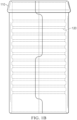
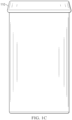
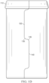
- Figures 1A-1F show various views of a split ring wire bundle seal sleeve 100.
- Examples include sleeve retaining ridge 110. Examples include multiple options and numbers of sleeve retaining ridges.
- examples can include retaining ridges 111 in addition to sleeve retaining ridge 110.
- examples include sealant gripping ridges 120. Examples include multiple options and number of shapes for sealant gripping ridges.
- the sealant gripping ridges can include triangular ridges 121.
- the sealant gripping ridges can include quadrilateral ridges 122.
- the sealant gripping ridges can include semi-cylindrical ridges 123.
- This one piece example is based on an elongated split ring including a first edge 130 comprising a first snap-fit latch mechanism 135.
- This example includes a second edge 140 comprising a second snap-fit latch mechanism 145.
- a two piece example can be based on exact matching parts interlocking to create a cylinder.
- a latching mechanism to keep cylinder from decoupling.
- This can include a keyed interface between the sleeve halves maintaining consistent, longitudinal and circumferential coupling.
- the external cylinder structure resists compression forces of assembled seal fittings.
- Outer surface of sleeve has ridges to mitigate sleeve migration when installed in flexible grommet.
- End of sleeve has a ridge to prevent longitudinal migration.
- the hard plastic split ring described herein improves the quality of the aerospace industry standard fuselage pressure bulkhead wire bundle seal via removing human induced variability from the manufacturing process. Examples save time. Examples are portable and easily deployed to point of use when and where needed.
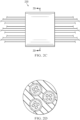
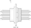
- Figures 2A-2E show steps for a split wire sleeve assembly process for use in pressure bulkhead seal fitting applications.
- Figure 2A shows a step 1 210.
- the goal of step 1 is to place sealant putty on the wires.
- Figure 2B shows a step 2 220.
- the goal of step 2 is to assemble the split wire sleeve around the putty and wires. Compressing the putty until the two halves of the wire sleeve snap together is advisable.
- Figure 2C shows a step 3 230.
- the goal of step 3 is to place assembled wire bundles inside the split compression seal grommet.
- the pressure grommets and the pressure seal fitting can be of multiple designs and still use the same wire sleeves.
- Figure 2D shows cross section AA.
- Figure 2E shows a step 4 240.
- the goal of step 4 is to assemble the split compression seal fitting around the grommet and then install the assembly on the pressure bolt feedthrough kit.
- Examples can include two hard plastic rings with a controlled outer diameter. These rings can be pressed around wire bundles, squeezing out any extra partially cured sealant tape between the wires to create a sealed section of the wire bundle.
- the rings will ideally contain snap features to hold them in place. They also include features to ensure correct alignment.
- each ring can optionally be held together by flag marker tape placed at each end; so that the seals would not be broken if mishandled by final assembly.
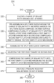
- Figure 3 shows a flowchart of a process 300 for assembling a split wire sleeve for a pressure bulkhead wire feedthrough seal fitting.
- the process begins at start operation 310.
- the process includes placing a charge of sealant putty around a set of wires.
- the process includes pre-assembling a split wire sleeve around the charge of sealant putty and wires, wherein the split wire sleeve comprises: an inner surface comprising a plurality of sealant putty gripping ridges; an outer surface comprising a sleeve retaining ridge; a first edge comprising a first snap-fit latch mechanism; and a second edge comprising a second snap-fit latch mechanism configured to snap-fit engage the first snap-fit latch mechanism.
- the process includes assembling the split wire sleeve.
- the process includes squeezing the first edge toward the second edge.
- the process includes compressing the charge of sealant putty until the first snap-fit latch mechanism and the second snap-fit latch mechanism engage together.
- the process includes creating a pressure resistant seal between the set of wires. The process terminates at stop operation 380.
- aircraft manufacturing and service method 400 may include specification and design 402 of aircraft 500 in Figure 5 and material procurement 404.
- aircraft 500 in Figure 5 During production, component and subassembly manufacturing 406 and system integration 408 of aircraft 500 in Figure 5 takes place. Thereafter, aircraft 500 in Figure 5 can go through certification and delivery 410 in order to be placed in service 412. While in service 412 by a customer, aircraft 500 in Figure 5 is scheduled for routine maintenance and service 414, which may include modification, reconfiguration, refurbishment, and other maintenance or service.
- Each of the processes of aircraft manufacturing and service method 400 may be performed or carried out by a system integrator, a third party, an operator, or some combination thereof.
- the operator may be a customer.
- a system integrator may include, without limitation, any number of aircraft manufacturers and major-system subcontractors
- a third party may include, without limitation, any number of vendors, subcontractors, and suppliers
- an operator may be an airline, a leasing company, a military entity, a service organization, and so on.
- aircraft 500 is produced by aircraft manufacturing and service method 400 in Figure 4 and may include airframe 502 with plurality of systems 504 and interior 506.
- systems 504 include one or more of propulsion system 508, electrical system 510, hydraulic system 512, and environmental system 514. Any number of other systems may be included.
- propulsion system 508 include one or more of propulsion system 508, electrical system 510, hydraulic system 512, and environmental system 514. Any number of other systems may be included.
- an aerospace example is shown, different illustrative examples may be applied to other industries, such as the automotive industry.
- Apparatuses and methods embodied herein may be employed during at least one of the stages of aircraft manufacturing and service method 400 in Figure 4 .
- components or subassemblies produced in component and subassembly manufacturing 406 in Figure 4 can be fabricated or manufactured in a manner similar to components or subassemblies produced while aircraft 500 is in service 412 in Figure 4 .
- one or more apparatus examples, method examples, or a combination thereof can be utilized during production stages, such as component and subassembly manufacturing 406 and system integration 408 in Figure 4 .
- One or more apparatus examples, method examples, or a combination thereof may be utilized while aircraft 500 is in service 412, during maintenance and service 414 in Figure 4 , or both.
- the use of a number of the different illustrative examples may substantially expedite the assembly of aircraft 500, reduce the cost of aircraft 500, or both expedite the assembly of aircraft 500 and reduce the cost of aircraft 500.
- a number of when used with reference to items, means one or more items.
- a number of different types of networks is one or more different types of networks.
- the phrase "at least one of,” when used with a list of items, means different combinations of one or more of the listed items can be used, and only one of each item in the list may be needed. In other words, “at least one of” means any combination of items and number of items may be used from the list, but not all of the items in the list are required.
- the item can be a particular object, a thing, or a category.
- At least one of item A, item B, or item C may include item A, item A and item B, or item B. This example also may include item A, item B, and item C or item B and item C. Of course, any combinations of these items can be present. In some illustrative examples, "at least one of” can be, for example, without limitation, two of item A; one of item B; and ten of item C; four of item B and seven of item C; or other suitable combinations.
- a component can be configured to perform the action or operation described.
- the component can have a configuration or design for a structure that provides the component an ability to perform the action or operation that is described in the illustrative examples as being performed by the component.
Landscapes
- Engineering & Computer Science (AREA)
- Architecture (AREA)
- Civil Engineering (AREA)
- Structural Engineering (AREA)
- Mechanical Engineering (AREA)
- Installation Of Indoor Wiring (AREA)
- Insulating Bodies (AREA)
- Electrical Discharge Machining, Electrochemical Machining, And Combined Machining (AREA)
Abstract
The present disclosure includes a split ring wire bundle seal sleeve and an assembly technology for pressurized electrical feedthroughs. A kit of parts is also described.
Description
- The present disclosure relates generally to wiring, such as wiring within the interior of transportation equipment. More particularly, the present disclosure relates to bulkhead feedthrough wiring in vehicles. Still more particularly, the present disclosure relates to methods and apparatus for air pressure tight sealing a split sleeve around wiring passing through a cabin pressure bulkhead. The description provides a disclosure of sealing process allowing for repair or replacement of feedthroughs without removal or disassembly of cabin monuments within a vehicle.
- Prior approaches to electrical feedthroughs in aircraft have too much human induced variability to result in a consistently acceptable product. Typically hand fitted together within an airframe, the feedthroughs can be complex machines.
- Prior approaches to feedthroughs also take an excessive amount of time. Trial and error results in the same operation being performed multiple times, and each operation requires a significant amount of time.
- Prior approaches can also create major problems for final assembly. Discovery of out of tolerance wire bundle diameters can occur as late as when both the plane and the wires are ready to be installed together on the plane.
- Another issue with feedthroughs is that they are costly to remove or move, such as during owner renovation or reconfiguration. There is a need for a more feedthrough flexible technology.
- Therefore, it would be desirable to have methods and apparatus that take into account a solution to at least some of the issues discussed above, as well as other possible issues. For example, it would be desirable to have methods and apparatus that overcome technical problems with sealing wire bundles passing through electrical feedthroughs in aircraft.
- The split ring wire bundle seal sleeve can operate as an internal component to compression seal fittings that pass electrical wiring through a pressure bulkhead. In examples, the two-piece, snap-together sleeve is assembled around wiring that has been treated with a sealant putty. The action of squeezing the sleeve halves together compresses the putty and creates a pressure resistant seal between the wires. The sleeve's latching mechanism maintains compression of the sealant while the sleeves internal ridges retain the putty and prevent air pressure from forcing it out of the sleeve. The wire sleeve can be manufactured in multiple configurations that are compatible with various wire bundle diameters and seal fitting design. Sealant retaining features, latch design, sleeve retaining features, length and diameter can be adapted to the application. The split wire sleeve is manufactured from a durable, non hygroscopic, glass fiber reinforced plastic.
- An example of the present disclosure provides a method of assembling a split wire sleeve for a pressure bulkhead wire feedthrough seal fitting, comprising:
placing a charge of sealant putty around a set of wires; pre-assembling a split wire sleeve around the charge of sealant putty and wires, wherein the split wire sleeve comprises: an inner surface comprising a plurality of sealant putty gripping ridges; an outer surface comprising a sleeve retaining ridge; a first edge comprising a first snap-fit latch mechanism; and a second edge comprising a second snap-fit latch mechanism configured to snap-fit engage the first snap-fit latch mechanism; and assembling the split wire sleeve comprising squeezing the first edge toward the second edge, compressing the charge of sealant putty until the first snap-fit latch mechanism and the second snap-fit latch mechanism engage together, and creating a pressure resistant seal between the set of wires. - The method may further comprise placing the split wire sleeve, the compressed charge of sealant putty and at least a segment of the set of wires within a conduit of a split compression seal grommet. Preferably, the method further comprises assembling a split compression seal fitting around the split compression seal grommet, and optionally installing the assembled split compression seal fitting on a pressure bulkhead.
- In another example of the present disclosure, a split wire sleeve for a pressure bulkhead wire feedthrough seal fitting comprises: a split sleeve having a first end and a second end, the split sleeve comprising: an inner surface comprising a plurality of sealant putty gripping ridges; an outer surface comprising a sleeve retaining ridge located at the first end; a first edge comprising a first snap-fit latch mechanism; and a second edge comprising a second snap-fit latch mechanism configured to snap-fit engage the first snap-fit latch mechanism.
- The first snap-fit latch mechanism and the second snap-fit latch mechanism may together cooperatively form a keyed interface to maintain consistent, longitudinal, and circumferential coupling when snap-fit engaged. Preferably, the plurality of sealant putty gripping ridges comprise triangular cross-section shaped sealant putty gripping ridges. Further preferably, the plurality of sealant putty gripping ridges comprise quadrilateral cross-section shaped sealant putty gripping ridges. Even further preferably, the plurality of sealant putty gripping ridges comprise hemi-cylindrical cross-section shaped sealant putty gripping ridges. Even further preferably, the plurality of sealant putty gripping ridges comprise a plurality of different cross-section shaped sealant putty gripping ridges, wherein optionally the plurality of different cross-section shaped sealant putty gripping ridges are arranged in repeating pattern sets, and further optionally wherein the plurality of different cross-section shaped sealant putty gripping ridges are arranged in repeating pattern sets defining a repeating pattern pitch interval selected from the group consisting of 3, 4, 5, 6 or 7.
- The outer surface may further comprise a plurality of sleeve retaining ridges to mitigate sleeve migration when installed in a compression seal grommet.
- The split wire sleeve may further comprise a set of wires mechanically coupled to and passing through both the split wire sleeve and the sealant putty.
- The split wire sleeve may further comprise a compression seal grommet mechanically coupled to the split wire sleeve. Preferably, the split wire sleeve further comprises a compression seal fitting mechanically coupled to the compression seal grommet, and optionally a compression seal fitting mechanically coupled to the compression seal grommet, and further optionally a pressure bulkhead mechanically coupled to the compression seal fitting.
- In another example of the present disclosure, a kit of parts for assembling a pressure bulkhead wire feedthrough seal fitting, comprises: a split sleeve, preferably having a first end and a second end, comprising a non-hygroscopic, glass fiber reinforced plastic, the split sleeve comprising: an inner surface comprising a plurality of sealant putty gripping ridges; an outer surface comprising a sleeve retaining ridge, preferably located at the first end; a first edge comprising a first snap-fit latch mechanism; and a second edge comprising a second snap-fit latch mechanism configured to snap-fit engage the first snap-fit latch mechanism; a source of sealant putty; and a compression seal grommet.
- The kit of parts may further comprise a compression seal fitting.
- The features and functions can be achieved independently in various examples of the present disclosure or may be combined in yet other examples in which further details can be seen with reference to the following description and drawings.
- The novel features believed characteristic of the illustrative examples are set forth in the appended claims. The illustrative examples, however, as well as a preferred mode of use, further objectives and features thereof, will best be understood by reference to the following detailed description of an illustrative example of the present disclosure when read in conjunction with the accompanying drawings, wherein:
-
Figures 1A-1F are illustrations a split wire sleeve in accordance with an illustrative example; -
Figures 2A-2E are illustration of a series of steps for assembly of a split wire sleeve in structural context in accordance with an illustrative example; -
Figure 3 is an illustration of a flowchart of a process of assembling a split wire sleeve for a pressure bulkhead wire feedthrough seal fitting in accordance with an illustrative example; -
Figure 4 is an illustration of an aircraft manufacturing and service method in accordance with an illustrative example; and -
Figure 5 is an illustration of a block diagram of an aircraft upon which an illustrative example may be implemented. - The illustrative examples recognize and take into account one or more different considerations as described below. For example,
Figures 1A-1F andFigures 2A-2E illustrate a split ring wire sleeve and a sealing process depicted in accordance with an illustrative example. 1) The split ring's diameter is controlled by the tolerances on the molds used to make it. It has no human induced variability. Optionally, the split rings can be placed in a hand-held press that is used to squeeze out the partially cured sealant tape during snap ring installation. This ensures enough partially cured sealant tape is present to make a wire bundle seal. - Sealant tape is a type, form, species or manifestation of sealant putty. Tape is typically formed on a web; putty is normally shipped and sold in a pot. It is the sealant properties of the materials that will lead one to the next working example; not form.
- The split ring process takes 52 minutes less time than the existing one to install the partially cured sealant tape. Furthermore, it eliminates the repetitive guess and check process inherent in the existing design; and eliminates the strap wrench and electrical tape winding steps entirely. It also eliminates the need to measure and mark the seal zone; as the snap ring is the seal zone.
-
Figures 1A-1F show various views of a split ring wire bundle seal sleeve 100. Examples includesleeve retaining ridge 110. Examples include multiple options and numbers of sleeve retaining ridges. Referring toFigure 1E , examples can include retainingridges 111 in addition tosleeve retaining ridge 110. Examples includesealant gripping ridges 120. Examples include multiple options and number of shapes for sealant gripping ridges. Referring toFigure 1F , the sealant gripping ridges can includetriangular ridges 121. The sealant gripping ridges can includequadrilateral ridges 122. The sealant gripping ridges can includesemi-cylindrical ridges 123. - This one piece example is based on an elongated split ring including a
first edge 130 comprising a first snap-fit latch mechanism 135. This example includes asecond edge 140 comprising a second snap-fit latch mechanism 145. - A two piece example can be based on exact matching parts interlocking to create a cylinder. In particular, a latching mechanism to keep cylinder from decoupling. This can include a keyed interface between the sleeve halves maintaining consistent, longitudinal and circumferential coupling. Circumferential ridges on inner surface grip sealant putty and prevent wires from migrating while seal fitting is under pressure. The ridges are designed so that they do not damage the wires.
- The external cylinder structure resists compression forces of assembled seal fittings. Outer surface of sleeve has ridges to mitigate sleeve migration when installed in flexible grommet. End of sleeve has a ridge to prevent longitudinal migration.
- The hard plastic split ring described herein improves the quality of the aerospace industry standard fuselage pressure bulkhead wire bundle seal via removing human induced variability from the manufacturing process. Examples save time. Examples are portable and easily deployed to point of use when and where needed.
-
Figures 2A-2E show steps for a split wire sleeve assembly process for use in pressure bulkhead seal fitting applications.Figure 2A shows astep 1 210. The goal ofstep 1 is to place sealant putty on the wires.Figure 2B shows a step 2 220. The goal of step 2 is to assemble the split wire sleeve around the putty and wires. Compressing the putty until the two halves of the wire sleeve snap together is advisable.Figure 2C shows a step 3 230. The goal of step 3 is to place assembled wire bundles inside the split compression seal grommet. The pressure grommets and the pressure seal fitting can be of multiple designs and still use the same wire sleeves.Figure 2D shows cross section AA.Figure 2E shows a step 4 240. The goal of step 4 is to assemble the split compression seal fitting around the grommet and then install the assembly on the pressure bolt feedthrough kit. - Examples can include two hard plastic rings with a controlled outer diameter. These rings can be pressed around wire bundles, squeezing out any extra partially cured sealant tape between the wires to create a sealed section of the wire bundle. The rings will ideally contain snap features to hold them in place. They also include features to ensure correct alignment. Finally, each ring can optionally be held together by flag marker tape placed at each end; so that the seals would not be broken if mishandled by final assembly.
-
Figure 3 shows a flowchart of aprocess 300 for assembling a split wire sleeve for a pressure bulkhead wire feedthrough seal fitting. The process begins atstart operation 310. Atoperation 320 the process includes placing a charge of sealant putty around a set of wires. Atoperation 330 the process includes pre-assembling a split wire sleeve around the charge of sealant putty and wires, wherein the split wire sleeve comprises: an inner surface comprising a plurality of sealant putty gripping ridges; an outer surface comprising a sleeve retaining ridge; a first edge comprising a first snap-fit latch mechanism; and a second edge comprising a second snap-fit latch mechanism configured to snap-fit engage the first snap-fit latch mechanism. Atoperation 340 the process includes assembling the split wire sleeve. Atoperation 350 the process includes squeezing the first edge toward the second edge. Atoperation 360 the process includes compressing the charge of sealant putty until the first snap-fit latch mechanism and the second snap-fit latch mechanism engage together. Atoperation 370 the process includes creating a pressure resistant seal between the set of wires. The process terminates atstop operation 380. - Illustrative examples of the disclosure may be described in the context of aircraft manufacturing and
service method 400 as shown inFigure 4 andaircraft 500 as shown inFigure 5 . Turning first toFigure 4 , an illustration of an aircraft manufacturing and service method is depicted in accordance with an illustrative example. During pre-production, aircraft manufacturing andservice method 400 may include specification anddesign 402 ofaircraft 500 inFigure 5 andmaterial procurement 404. - During production, component and
subassembly manufacturing 406 andsystem integration 408 ofaircraft 500 inFigure 5 takes place. Thereafter,aircraft 500 inFigure 5 can go through certification anddelivery 410 in order to be placed inservice 412. While inservice 412 by a customer,aircraft 500 inFigure 5 is scheduled for routine maintenance andservice 414, which may include modification, reconfiguration, refurbishment, and other maintenance or service. - Each of the processes of aircraft manufacturing and
service method 400 may be performed or carried out by a system integrator, a third party, an operator, or some combination thereof. In these examples, the operator may be a customer. For the purposes of this description, a system integrator may include, without limitation, any number of aircraft manufacturers and major-system subcontractors; a third party may include, without limitation, any number of vendors, subcontractors, and suppliers; and an operator may be an airline, a leasing company, a military entity, a service organization, and so on. - With reference now to
Figure 5 , an illustration of an aircraft is depicted in which an illustrative example may be implemented. In this example,aircraft 500 is produced by aircraft manufacturing andservice method 400 inFigure 4 and may includeairframe 502 with plurality ofsystems 504 and interior 506. Examples ofsystems 504 include one or more ofpropulsion system 508,electrical system 510,hydraulic system 512, andenvironmental system 514. Any number of other systems may be included. Although an aerospace example is shown, different illustrative examples may be applied to other industries, such as the automotive industry. - Apparatuses and methods embodied herein may be employed during at least one of the stages of aircraft manufacturing and
service method 400 inFigure 4 . - In one illustrative example, components or subassemblies produced in component and
subassembly manufacturing 406 inFigure 4 can be fabricated or manufactured in a manner similar to components or subassemblies produced whileaircraft 500 is inservice 412 inFigure 4 . As yet another example, one or more apparatus examples, method examples, or a combination thereof can be utilized during production stages, such as component andsubassembly manufacturing 406 andsystem integration 408 inFigure 4 . One or more apparatus examples, method examples, or a combination thereof may be utilized whileaircraft 500 is inservice 412, during maintenance andservice 414 inFigure 4 , or both. The use of a number of the different illustrative examples may substantially expedite the assembly ofaircraft 500, reduce the cost ofaircraft 500, or both expedite the assembly ofaircraft 500 and reduce the cost ofaircraft 500. - As used herein, "a number of" when used with reference to items, means one or more items. For example, "a number of different types of networks" is one or more different types of networks.
- Further, the phrase "at least one of," when used with a list of items, means different combinations of one or more of the listed items can be used, and only one of each item in the list may be needed. In other words, "at least one of" means any combination of items and number of items may be used from the list, but not all of the items in the list are required. The item can be a particular object, a thing, or a category.
- For example, without limitation, "at least one of item A, item B, or item C" may include item A, item A and item B, or item B. This example also may include item A, item B, and item C or item B and item C. Of course, any combinations of these items can be present. In some illustrative examples, "at least one of" can be, for example, without limitation, two of item A; one of item B; and ten of item C; four of item B and seven of item C; or other suitable combinations.
- The description of the different illustrative examples has been presented for purposes of illustration and description and is not intended to be exhaustive or limited to the examples in the form disclosed. The different illustrative examples describe components that perform actions or operations. In an illustrative example, a component can be configured to perform the action or operation described. For example, the component can have a configuration or design for a structure that provides the component an ability to perform the action or operation that is described in the illustrative examples as being performed by the component. Further, To the extent that terms "includes", "including", "has", "contains", and variants thereof are used herein, such terms are intended to be inclusive in a manner similar to the term "comprises" as an open transition word without precluding any additional or other elements.
- Many modifications and variations will be apparent to those of ordinary skill in the art. Further, different illustrative examples may provide different features as compared to other desirable examples. The example or examples selected are chosen and described in order to best explain the principles of the examples, the practical application, and to enable others of ordinary skill in the art to understand the disclosure for various examples with various modifications as are suited to the particular use contemplated.
Claims (15)
- A split wire sleeve for a pressure bulkhead wire feedthrough seal fitting, comprising:
a split sleeve having a first end and a second end, the split sleeve comprising:an inner surface comprising a plurality of sealant putty gripping ridges (111);an outer surface comprising a sleeve retaining ridge (110) located at the first end;a first edge (130) comprising a first snap-fit latch mechanism (135); anda second edge (140) comprising a second snap-fit latch mechanism (145) configured to snap-fit engage the first snap-fit latch mechanism. - The split wire sleeve of claim 1, wherein the first snap-fit latch mechanism and the second snap-fit latch mechanism together cooperatively form a keyed interface to maintain consistent, longitudinal, and circumferential coupling when snap-fit engaged.
- The split wire sleeve of claim 2, wherein the plurality of sealant putty gripping ridges (111) comprise triangular cross-section shaped sealant putty gripping ridges.
- The split wire sleeve of claim 2 or 3, wherein the plurality of sealant putty gripping ridges (111) comprise quadrilateral cross-section shaped sealant putty gripping ridges.
- The split wire sleeve of any one of claims 2-4, wherein the plurality of sealant putty gripping ridges (111) comprise hemi-cylindrical cross-section shaped sealant putty gripping ridges.
- The split wire sleeve of any one of claims 2-5, wherein the plurality of sealant putty gripping ridges (111) comprise a plurality of different cross-section shaped sealant putty gripping ridges.
- The split wire sleeve of claim 6, wherein the plurality of different cross-section shaped sealant putty gripping ridges (111) are arranged in repeating pattern sets, preferably wherein
the plurality of different cross-section shaped sealant putty gripping ridges (111) are arranged in repeating pattern sets defining a repeating pattern pitch interval selected from the group consisting of 3, 4, 5, 6 or 7. - The split wire sleeve of any one of claims 1-7, wherein:the outer surface further comprises a plurality of sleeve retaining ridges (110) to mitigate sleeve migration when installed in a compression seal grommet; and/orthe split wire sleeve further comprises a set of wires mechanically coupled to and passing through both the split wire sleeve and the sealant putty.
- The split wire sleeve of any one of claims 1-8, further comprising a compression seal grommet mechanically coupled to the split wire sleeve.
- The split wire sleeve of claim 9, further comprising a compression seal fitting mechanically coupled to the compression seal grommet, and preferably further comprising:
a compression seal fitting mechanically coupled to the compression seal grommet, and further preferably further comprising:
a pressure bulkhead mechanically coupled to the compression seal fitting. - A method of assembling a split wire sleeve for a pressure bulkhead wire feedthrough seal fitting, comprising:placing a charge of sealant putty around a set of wires;pre-assembling a split wire sleeve around the charge of sealant putty and wires, wherein the split wire sleeve comprises:an inner surface comprising a plurality of sealant putty gripping ridges;an outer surface comprising a sleeve retaining ridge (110);a first edge (130) comprising a first snap-fit latch mechanism (135); anda second edge (140) comprising a second snap-fit latch mechanism (145) configured to snap-fit engage the first snap-fit latch mechanism (135); andassembling the split wire sleeve comprising squeezing the first edge (130) toward the second edge (140), compressing the charge of sealant putty until the first snap-fit latch mechanism (135) and the second snap-fit latch mechanism (145) engage together, and creating a pressure resistant seal between the set of wires.
- The method of claim 11, further comprising placing the split wire sleeve, the compressed charge of sealant putty and at least a segment of the set of wires within a conduit of a split compression seal grommet.
- The method of claim 12, further comprising assembling a split compression seal fitting around the split compression seal grommet, and preferably further comprising:
installing the assembled split compression seal fitting on a pressure bulkhead. - A kit of parts for assembling a pressure bulkhead wire feedthrough seal fitting, comprising:a split sleeve comprising a non-hygroscopic, glass fiber reinforced plastic, the split sleeve comprising:an inner surface comprising a plurality of sealant putty gripping ridges (111);an outer surface comprising a sleeve retaining ridge (110);a first edge (130) comprising a first snap-fit latch mechanism (135); anda second edge (140) comprising a second snap-fit latch mechanism (145) configured to snap-fit engage the first snap-fit latch mechanism (135);a source of sealant putty; anda compression seal grommet.
- The kit of parts of claim 14, further comprising a compression seal fitting.
Applications Claiming Priority (1)
| Application Number | Priority Date | Filing Date | Title |
|---|---|---|---|
| US18/339,028 US12463409B2 (en) | 2023-06-21 | 2023-06-21 | Split ring wire bundle seal sleeve and assembly process |
Publications (1)
| Publication Number | Publication Date |
|---|---|
| EP4481967A1 true EP4481967A1 (en) | 2024-12-25 |
Family
ID=91376033
Family Applications (1)
| Application Number | Title | Priority Date | Filing Date |
|---|---|---|---|
| EP24179497.3A Pending EP4481967A1 (en) | 2023-06-21 | 2024-06-03 | Split ring wire bundle seal sleeve and assembly process |
Country Status (3)
| Country | Link |
|---|---|
| US (1) | US12463409B2 (en) |
| EP (1) | EP4481967A1 (en) |
| CA (1) | CA3242494A1 (en) |
Families Citing this family (3)
| Publication number | Priority date | Publication date | Assignee | Title |
|---|---|---|---|---|
| USD1086863S1 (en) * | 2024-04-30 | 2025-08-05 | Gaatu Inc | Fastener for mesh closet rack |
| USD1119549S1 (en) * | 2024-05-28 | 2026-03-24 | Hangzhou Maoqi Import and Export Trade Co. | Chair clamp |
| US20250327536A1 (en) * | 2025-07-01 | 2025-10-23 | Fan Jiang | Faucet Raw Material Silicone Sleeve |
Citations (4)
| Publication number | Priority date | Publication date | Assignee | Title |
|---|---|---|---|---|
| JPH08335419A (en) * | 1995-06-07 | 1996-12-17 | Sumitomo Wiring Syst Ltd | Grommet installation structure |
| US6218625B1 (en) * | 1998-10-02 | 2001-04-17 | Lear Automotive Dearborn, Inc. | Grommet |
| FR2991114A1 (en) * | 2012-05-25 | 2013-11-29 | Renault Sa | Device for penetration of electrical loom by opening in partition in car, has half-shells that are ready to close itself around loom, and rigid material parts surrounding two half-shells, where parts are assembled in water-tight manner |
| JP2021166417A (en) * | 2020-04-06 | 2021-10-14 | 株式会社ブレスト工業研究所 | Cover for cable lead-in port and construction method of cover |
Family Cites Families (15)
| Publication number | Priority date | Publication date | Assignee | Title |
|---|---|---|---|---|
| GB2186440B (en) * | 1986-02-11 | 1990-03-14 | Hawke Cable Glands Ltd | Improved transit for cables and pipes |
| US5545854A (en) * | 1993-12-29 | 1996-08-13 | Yazaki Corporation | Grommet for wire sealing |
| JPH07245030A (en) * | 1994-03-07 | 1995-09-19 | Sumitomo Wiring Syst Ltd | Grommet |
| JP3427949B2 (en) * | 1994-07-19 | 2003-07-22 | 住友電装株式会社 | Grommet |
| US6180882B1 (en) * | 1999-01-19 | 2001-01-30 | Thomas & Betts, International | Single and dual cable seal system |
| NL1016703C2 (en) * | 2000-11-24 | 2002-05-27 | Beele Eng Bv | Feeding device. |
| JP3940308B2 (en) * | 2002-03-27 | 2007-07-04 | 矢崎総業株式会社 | Harness fixture |
| US7534965B1 (en) * | 2008-01-29 | 2009-05-19 | Thompson David M | Cable grommet with ball and socket |
| GB2478777B (en) * | 2010-03-18 | 2015-05-20 | Cable Man Products Ltd | Barrier for a barrier connector |
| US9365170B2 (en) * | 2012-08-23 | 2016-06-14 | Yazaki North America, Inc. | Grommet assembly |
| ES2626753T3 (en) * | 2012-08-30 | 2017-07-25 | Beele Engineering B.V. | Sealing system for an annular space |
| US10113669B2 (en) * | 2016-01-15 | 2018-10-30 | The Boeing Company | Pass-through bulkhead seal fitting |
| US11056867B2 (en) * | 2017-04-18 | 2021-07-06 | Oblamatik Ag | Installation apparatus consisting of a wall plug and a holder which can be screwed therein for installing flush-mounted devices |
| US9944239B1 (en) * | 2017-05-19 | 2018-04-17 | Newfrey Llc | Fluid and dust resistant split grommet |
| US11848547B1 (en) * | 2022-05-27 | 2023-12-19 | Richard Burant | Cable protection sleeve |
-
2023
- 2023-06-21 US US18/339,028 patent/US12463409B2/en active Active
-
2024
- 2024-06-03 EP EP24179497.3A patent/EP4481967A1/en active Pending
- 2024-06-20 CA CA3242494A patent/CA3242494A1/en active Pending
Patent Citations (4)
| Publication number | Priority date | Publication date | Assignee | Title |
|---|---|---|---|---|
| JPH08335419A (en) * | 1995-06-07 | 1996-12-17 | Sumitomo Wiring Syst Ltd | Grommet installation structure |
| US6218625B1 (en) * | 1998-10-02 | 2001-04-17 | Lear Automotive Dearborn, Inc. | Grommet |
| FR2991114A1 (en) * | 2012-05-25 | 2013-11-29 | Renault Sa | Device for penetration of electrical loom by opening in partition in car, has half-shells that are ready to close itself around loom, and rigid material parts surrounding two half-shells, where parts are assembled in water-tight manner |
| JP2021166417A (en) * | 2020-04-06 | 2021-10-14 | 株式会社ブレスト工業研究所 | Cover for cable lead-in port and construction method of cover |
Also Published As
| Publication number | Publication date |
|---|---|
| US20240429694A1 (en) | 2024-12-26 |
| CA3242494A1 (en) | 2025-06-09 |
| US12463409B2 (en) | 2025-11-04 |
Similar Documents
| Publication | Publication Date | Title |
|---|---|---|
| US12463409B2 (en) | Split ring wire bundle seal sleeve and assembly process | |
| US10399283B2 (en) | Method and device for producing contoured composite laminate stiffeners with reduced wrinkling | |
| US8691137B2 (en) | Method of molding partus using a tool sleeve for mold die | |
| US10850489B2 (en) | Systems and methods for constructing complex composite structures | |
| US7518058B1 (en) | Powerfeeder spacer | |
| US8511359B2 (en) | Layup mandrel having changeable shape and method of using the same | |
| US20100139857A1 (en) | Bagging process and mandrel for fabrication of elongated composite structure | |
| US20210260795A1 (en) | Methods and systems for forming curved composite charges for stringers | |
| CN110077014A (en) | Composite construction and method | |
| US10286998B2 (en) | Mechanical fastening system and associated structural assembly and method | |
| JP2021151771A (en) | Method and device for supporting a variety of different pre-cured composite stringers | |
| US20150190836A1 (en) | Masking Plug | |
| EP2818307B1 (en) | Fuselage mandrel insert and method using it | |
| AU2018236869B2 (en) | Layup tools that facilitate transfer of laminates to cure tools | |
| US20140377076A1 (en) | Joint assembly and method of forming thereof | |
| US10040536B2 (en) | Wing structure, stringer structure, and related apparatus and methods of assembly | |
| US8376337B2 (en) | Elliptical locating apparatus | |
| US8622109B2 (en) | Pressure debulking system and method | |
| CN105905311B (en) | Method, system and apparatus for assembling composite wing skins with stiffeners | |
| WO2010138250A1 (en) | Angled locating apparatus | |
| CN113800002B (en) | Flexible truss system and method of transferring flexible composite parts using such a system | |
| EP4721960A1 (en) | Composite stringer packages and systems and methods for constructing composite stringer packages | |
| EP3023231B1 (en) | Systems and methods for compacting a charge of composite material | |
| EP3741545B1 (en) | Method of applying stiffener assemblies to a mandrel | |
| AU2021202851B2 (en) | Flexible truss systems and methods of transferring flexible composite parts using such systems |
Legal Events
| Date | Code | Title | Description |
|---|---|---|---|
| PUAI | Public reference made under article 153(3) epc to a published international application that has entered the european phase |
Free format text: ORIGINAL CODE: 0009012 |
|
| STAA | Information on the status of an ep patent application or granted ep patent |
Free format text: STATUS: THE APPLICATION HAS BEEN PUBLISHED |
|
| AK | Designated contracting states |
Kind code of ref document: A1 Designated state(s): AL AT BE BG CH CY CZ DE DK EE ES FI FR GB GR HR HU IE IS IT LI LT LU LV MC ME MK MT NL NO PL PT RO RS SE SI SK SM TR |
|
| STAA | Information on the status of an ep patent application or granted ep patent |
Free format text: STATUS: REQUEST FOR EXAMINATION WAS MADE |
|
| 17P | Request for examination filed |
Effective date: 20250624 |