EP4481946A1 - Flexible liquid metal microfiber system and method of controlling a flexible liquid metal microfiber system - Google Patents
Flexible liquid metal microfiber system and method of controlling a flexible liquid metal microfiber system Download PDFInfo
- Publication number
- EP4481946A1 EP4481946A1 EP23181314.8A EP23181314A EP4481946A1 EP 4481946 A1 EP4481946 A1 EP 4481946A1 EP 23181314 A EP23181314 A EP 23181314A EP 4481946 A1 EP4481946 A1 EP 4481946A1
- Authority
- EP
- European Patent Office
- Prior art keywords
- liquid metal
- flexible liquid
- metal microfiber
- section
- microfiber
- Prior art date
- Legal status (The legal status is an assumption and is not a legal conclusion. Google has not performed a legal analysis and makes no representation as to the accuracy of the status listed.)
- Pending
Links
Images

Classifications
-
- H—ELECTRICITY
- H01—ELECTRIC ELEMENTS
- H01Q—ANTENNAS, i.e. RADIO AERIALS
- H01Q9/00—Electrically-short antennas having dimensions not more than twice the operating wavelength and consisting of conductive active radiating elements
- H01Q9/04—Resonant antennas
- H01Q9/30—Resonant antennas with feed to end of elongated active element, e.g. unipole
- H01Q9/32—Vertical arrangement of element
-
- H—ELECTRICITY
- H01—ELECTRIC ELEMENTS
- H01Q—ANTENNAS, i.e. RADIO AERIALS
- H01Q21/00—Antenna arrays or systems
- H01Q21/06—Arrays of individually energised antenna units similarly polarised and spaced apart
- H01Q21/08—Arrays of individually energised antenna units similarly polarised and spaced apart the units being spaced along or adjacent to a rectilinear path
-
- H—ELECTRICITY
- H01—ELECTRIC ELEMENTS
- H01Q—ANTENNAS, i.e. RADIO AERIALS
- H01Q3/00—Arrangements for changing or varying the orientation or the shape of the directional pattern of the waves radiated from an antenna or antenna system
- H01Q3/01—Arrangements for changing or varying the orientation or the shape of the directional pattern of the waves radiated from an antenna or antenna system varying the shape of the antenna or antenna system
-
- H—ELECTRICITY
- H01—ELECTRIC ELEMENTS
- H01Q—ANTENNAS, i.e. RADIO AERIALS
- H01Q3/00—Arrangements for changing or varying the orientation or the shape of the directional pattern of the waves radiated from an antenna or antenna system
- H01Q3/26—Arrangements for changing or varying the orientation or the shape of the directional pattern of the waves radiated from an antenna or antenna system varying the relative phase or relative amplitude of energisation between two or more active radiating elements; varying the distribution of energy across a radiating aperture
- H01Q3/2682—Time delay steered arrays
Definitions
- the invention relates to a flexible liquid metal microfiber system. Further, the invention relates to a method of controlling a flexible liquid metal microfiber system.
- antennas are known that typically have at least one antenna element with a fixed length, resulting in a fixed resonance frequency of the respective antenna.
- the length of the respective antenna element has to be set accordingly, namely by trimming the length to equal a quarter wavelength associated with the desired resonance frequency.
- two antenna elements are used, each having a length that equals a quarter wavelength associated with the desired resonance frequency.
- the antenna only has a single antenna element that is located above a ground plane, wherein the length of the single antenna element equals a quarter wavelength at the desired resonance frequency.
- the at least one antenna element is typically made of a solid metal rod such that no further adjustment is possible anymore once the length of the antenna element has been set. Accordingly, an adaption of the resonance frequency is not possible anymore.
- the antenna can also be operated outside of its resonance frequency, but the efficiency is lowered since the antenna does not work in its optimized operational range.
- one side of an antenna line is attached to the lower end of the first flexible liquid metal microfiber section, whereas the other side is attached to the ground plane.
- the flexible liquid metal microfiber is a single strand of microfiber that comprises the two flexible liquid metal microfiber sections, namely the first flexible liquid metal microfiber section that acts as an antenna element as well as the second flexible liquid metal microfiber section.
- the flexible liquid metal microfiber system comprises an actuating element that is interconnected between the first adjustment device and the second end of the first flexible liquid metal microfiber section.
- the first adjustment device is configured to pull or release the actuating element, thereby initiating a movement of the actuating element which transfers the action initiated by the adaption device to the first flexible liquid metal microfiber section, thereby adapting the length of the first flexible liquid metal microfiber section.
- the first flexible liquid metal microfiber section is stretched in case the first adjustment device pulls the actuating element.
- the first flexible liquid metal microfiber section tries to get back into its original state due to its inherent elastic characteristics.
- the flexible liquid metal microfiber is reversibly elastic.
- the flexible liquid metal microfiber, particularly the first flexible liquid metal microfiber section gets back into its original state once no stretching force is applied, e.g. once a releasing takes place.
- the actuating element is a string that is guided along at least one pulley.
- the pulley may be part of a radiofrequency inert structure, for instance a cantilever.
- the radiofrequency inert structure may have an L-shape, wherein two separately formed pulleys may be provided, particularly one at the edge at which the long part and the short part merge into each other and/or another one at the free end of the short part.
- the radiofrequency inert structure having the L-shape may be connected via the free end of the long part to the ground plane.
- the pulleys guide the actuating element, namely the string, along the radiofrequency inert structure.
- the adjustment device may be configured to adapt the length of the first flexible liquid metal microfiber section, thereby tuning a resonance frequency.
- the first flexible liquid metal microfiber section may act as the antenna element of an antenna, particularly a monopole antenna, the resonance frequency of which is adapted accordingly by adapting the length of the antenna element, namely the first flexible liquid metal microfiber section.
- the second flexible liquid metal microfiber section is fixed via a first end to the ground plane, particularly in an electrically-isolated manner. Therefore, both flexible liquid metal microfiber sections are fixed to the same ground plane via their first ends.
- the single strand of microfiber namely the flexible liquid metal microfiber having the first and the second flexible liquid metal microfiber sections, may be portioned into both sections by the ground plane.
- the ground plane particularly the fixation of the flexible liquid metal microfiber to the ground plane, ensures that only the first flexible liquid metal microfiber section may be adapted with respect to its length, whereas the second flexible liquid metal microfiber section remains at its length.
- a second end of the second flexible liquid metal microfiber section is connected with a second adjustment device that is configured to adapt the length of the second flexible liquid metal microfiber section.
- the length of the second flexible liquid metal microfiber section may also be adapted by means of the second adjustment device.
- the lengths of both sections namely the first flexible liquid metal microfiber section and the second flexible liquid metal microfiber section, may be adapted independently of each other since both sections are fixed to the ground plane via their first ends and to the respective adjustment devices via their second ends.
- the first adjustment device and the second adjustment device may be integrated within a common housing, thereby establishing an adjustment box. Both adjustment devices may relate to stretchers that are capable of stretching the respective flexible liquid metal microfiber section (independently).
- the second flexible liquid metal microfiber section acts as a phase shifter.
- a phase shifter has a trombone line that, however, is replaced by the second flexible liquid metal microfiber section.
- the second flexible liquid metal microfiber section may be connected to an output line, e.g. via an electrical contact associated with the second end of the second flexible liquid metal microfiber.
- the second flexible liquid metal microfiber ensures that a reconfigurable phase shifter is obtained that is light and easy to set.
- the second flexible liquid metal microfiber section is used as a delay line in order to introduce a delay, thereby shifting the phase of a signal in the radio frequency domain.
- a different delay is introduced by adapting the length of the second flexible liquid metal microfiber section, thereby adapting the properties of the liquid metal of the second flexible liquid metal microfiber section.
- a unique property of the second flexible liquid metal microfiber section is used for setting the delay introduced by the second flexible liquid metal microfiber section so as to shift the phase.
- a different delay is introduced, thereby shifting the phase of the respective signal processed by the second flexible liquid metal microfiber section differently in a defined manner
- the second flexible liquid metal microfiber section and the first flexible liquid metal microfiber section are electrically connected with each other, as they are part of the same microfiber strand.
- a continuous electrical conductor is provided by the flexible liquid metal microfiber having both the first flexible liquid metal microfiber section and the second flexible liquid metal microfiber section.
- the first flexible liquid metal microfiber section and the second flexible liquid metal microfiber section merge into each other or rather are connected with each other in an uninterruptible manner.
- both sections have different functions, namely tuning and phase shifting.
- the first flexible liquid metal microfiber section provides the tunable antenna element and the second flexible liquid metal microfiber section provides the phase shifter.
- the second flexible liquid metal microfiber section is housed within a shielded box.
- the shielded box may be connected to the ground member.
- the shielded box may be made of an electrically conductive material.
- the shielded box is (electrically) connected with the ground plane, the shielded box is electrically grounded.
- the shielded box ensures that the second flexible liquid metal microfiber section is not exposed to the surrounding air contrary to the first flexible liquid metal microfiber section. This ensures that the second flexible liquid metal microfiber section does not act as a radiating element, e.g. an antenna element.
- the first flexible liquid metal microfiber section and the second flexible liquid metal microfiber section may be located on opposite sides with respect to the ground plane.
- the first flexible liquid metal microfiber section and the second flexible liquid metal microfiber section may be located in two planes that are perpendicular with respect to each other. Therefore, a compact flexible liquid metal microfiber system, particularly a compact antenna, with regard to one dimension, e.g. length or rather height, is ensured as both flexible liquid metal microfiber sections are oriented towards different directions, namely perpendicular directions.
- first flexible liquid metal microfiber section and the second flexible liquid metal microfiber section together may establish a flexible liquid metal microfiber dual function unit.
- the flexible liquid metal microfiber dual function unit is established by the single microfiber strand having the two sections with different functions, particularly due to their different arrangements.
- the respective flexible liquid metal microfiber sections act as an antenna element and a phase shifter, thereby providing the two different functions.
- the flexible liquid metal microfiber namely the single microfiber strand, simultaneously acts as the antenna element and the phase shifter.
- the flexible liquid metal microfiber system comprises several flexible liquid metal microfiber dual function units, e.g. several flexible liquid metal microfibers, namely several microfiber strands.
- the several flexible liquid metal microfiber dual function units are arranged in an array.
- the flexible liquid metal microfiber system is transformed into a beam forming system.
- the several flexible liquid metal microfiber dual function units ensure that the flexible liquid metal microfiber system establishes a beam forming system or rather an antenna with directional characteristics, for instance for direction finding.
- the several flexible liquid metal microfiber dual function units are spaced from each other by a distance that corresponds to a half wavelength.
- the several flexible liquid metal microfiber dual function units may be arranged on a bar in a displaceable manner such that the relative positions can be varied, thereby adapting the distances among the flexible liquid metal microfiber dual function units, e.g. adapting the relative distances to the intended operation frequency.
- the respective second flexible liquid metal microfiber sections of the several flexible liquid metal microfiber dual function units may be coupled to a common second adjustment device, particularly a common displacement member actuated by the single common second adjustment device.
- the common displacement member may be pivoted about a pivot point in order to adapt the lengths of the second flexible liquid metal microfiber sections.
- the pivoting of the common displacement member ensures that the lengths of the second flexible liquid metal microfiber sections are adapted simultaneously, but differently.
- the common displacement member causes a dependent length adaption of the respective second flexible liquid metal microfiber sections.
- each of the several flexible liquid metal microfiber dual function units is connected an own second adjustment device. This setup ensures an independent length adaption of the respective second flexible liquid metal microfiber sections.
- the flexible liquid metal microfiber system comprises a first operation mode in which the flexible liquid metal microfiber system acts as a tunable monopole antenna as well as a second operation mode in which the flexible liquid metal microfiber system acts as a directional antenna or a beam steering device.
- the first flexible liquid metal microfiber section may be adapted with respect to its length, thereby tuning the resonance frequency of the antenna accordingly.
- a phase shift may be introduced.
- beam steering operations can be performed.
- antenna and phase shifter are integrated into one system, namely a single system, which is established by the flexible liquid metal microfiber system, particularly the single flexible liquid metal microfiber having the two sections that can be stretched independently of each other.
- one flexible liquid metal microfiber is provided that is partitioned into dual functions, namely the sections.
- One section behaves as the tunable antenna and the remaining section as the phase shifter.
- each of the sections may be fixed to the ground plane. Consequently, each of the sections can be adapted in its length individually and independently of each other. Particularly, each of the sections is connected to a corresponding adjustment device.
- the respective adjustment device may be a programmable device, e.g. a programmable stretcher.
- the invention also provides a method of controlling a flexible liquid metal microfiber system that comprises a ground member and a flexible liquid metal microfiber having a first flexible liquid metal microfiber section and a second flexible liquid metal microfiber section.
- the first section flexible liquid metal microfiber section is fixed via a first end to the ground member.
- a length of the first flexible liquid metal microfiber section is adapted by means of a first adjustment device that is connected to a second end of the first flexible liquid metal microfiber section, thereby tuning a resonance frequency.
- An aspect provides that a length of the second flexible liquid metal microfibers adapted by means of a second adjustment device that is connected to a second end of the second flexible liquid metal microfiber, thereby shifting a phase.
- the phrase "at least one of A, B, and C", for example, means (A), (B), (C), (A and B), (A and C), (B and C), or (A, B, and C), including all further possible permutations when more than three elements are listed.
- the term “at least one of A and B” generally means “A and/or B", namely "A” alone, “B” alone or "A and B”.
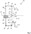
- a flexible liquid metal microfiber system 10 that comprises a ground plane 12 that is established by an electrically conductive part.
- the flexible liquid metal microfiber system 10 comprises a single flexible liquid metal microfiber 13 that has a first flexible liquid metal microfiber section 14 as well as a second flexible liquid metal microfiber section 16.
- both flexible liquid metal microfiber sections 14, 16 are fixed to the ground plane 12 via respective first ends 18, 20, namely at a fixation point 21. The fixation is done in an electrically isolated manner. Both flexible liquid metal microfiber sections 14, 16 are located at opposite sides of the ground plane 12.
- the flexible liquid metal microfiber sections 14, 16 each comprise a second end 22, 24 that are connected to a respective actuating element 26, 28.
- Each of the actuating elements 26, 28 is connected to a respective adjustment device 30, 32.
- the adjustment devices 30, 32 may be commonly housed in a housing, also called adjustment box.
- first flexible liquid metal microfiber section 14 is connected to the first adjustment device 30 via the first actuating element 26.
- the second flexible liquid metal microfiber section 16 is connected to the second adjustment device 32 via the second actuating element 28.
- the actuating elements 26, 28 are each established by (nylon) strings that are guided via pulleys 34.
- the respective pulleys 34 are located at the respective free end of the short part of the radiofrequency inert structures 36 as well as the points at which the respective long part and the respective short part merge into each other. Hence, the actuating elements 26, 28 are guided about the edges of the L-shaped radiofrequency inert structures 36.
- the actuating elements 26, 28 are actuated by the adjustment devices 30, 32 such that the respective flexible liquid metal microfiber section 14, 16 connected with the respective actuating element 26, 28 is released or stressed, which depends on the actuation initiated by the adjustment devices 30, 32.
- both sections 14, 16 namely the first flexible liquid metal microfiber section 14 and the second flexible liquid metal microfiber section 16 can be adapted independently of each other since both sections 14, 16 are fixed to the ground plane 12 via their respective first end 18, 20 and to the respective adjustment devices 30, 32 via their respective second end 22, 24.
- the length of the second flexible liquid metal microfiber section 16 can be adapted in a similar manner by means of the second adjustment device 32 and the corresponding actuating element 28.
- the lengths of the first flexible liquid metal microfiber section 14 and the second flexible liquid metal microfiber section 16 can be adapted independently of each other, as the flexible liquid metal microfiber 13 is fixedly connected to the ground plane 12 at the fixation point 21. Hence, the flexible liquid metal microfiber 13 is portioned into the first flexible liquid metal microfiber section 14 and the second flexible liquid metal microfiber section 16 by means of the fixation to the ground plane 12.
- the first flexible liquid metal microfiber section 14 Since the first flexible liquid metal microfiber section 14 is exposed to the surrounding air, the first flexible liquid metal microfiber section 14 acts as an antenna element 44.
- a resonance frequency of an antenna having the antenna element 44 is adapted.
- the adaption of the length of the first flexible liquid metal microfiber section 14 relates to an adaption of the length of the antenna element 44, thereby adapting or rather tuning the resonance frequency of the antenna.
- the second flexible liquid metal microfiber section 16 is not exposed to the surrounding air, as a shielded box 46 is provided that surrounds the second flexible liquid metal microfiber section 16.
- the shielded box 46 may be made of an electrically conductive material, e.g. a metal. Moreover, the shielded box 46 may be electrically connected to the ground plane 12.
- the second flexible liquid metal microfiber section 16 housed in the shielded box 46 does not contribute to the radiation pattern of the antenna. Actually, the second flexible liquid metal microfiber section 16 acts as a phase shifter 48 when adapting its length by means of the second adjustment device 32.
- the second end of the second flexible liquid metal microfiber section 16, namely the one having the electrical contact 42, is connected with a line 50 that may be connected to a transmitter, a receiver or a transceiver. Accordingly, a radio frequency signal may be transmitted or rather received by means of the flexible liquid metal microfiber system 10.
- the flexible liquid metal microfiber system 10 shown in Figure 1 has two different operation modes, as it can be operated as a tunable monopole antenna as well as a directional antenna due to the phase shifting.
- the first flexible liquid metal microfiber section 14 relates to the monopole of the tunable monopole antenna, namely the antenna element 44, whereas the second flexible liquid metal microfiber section 16 relates to the phase shifter 48. Since both sections 14, 16 are part of the flexible liquid metal microfiber 13, namely the single microfiber strand, which has two functions.
- first flexible liquid metal microfiber section 14 as well as the second flexible liquid metal microfiber section 16 together form a flexible liquid metal microfiber dual function unit 52, e.g. the flexible liquid metal microfiber 13, namely the single microfiber strand, which provides the respective two functions described above.
- first flexible liquid metal microfiber section 14 and the second flexible liquid metal microfiber section 16 are illustrated to run along the same direction, it is also possible that the first flexible liquid metal microfiber section 14 and the second flexible liquid metal microfiber section 16 are located in two planes being perpendicular with respect to each other. Therefore, a compact flexible liquid metal microfiber system 10, particularly a compact antenna, with regard to one dimension, e.g. length or rather height, is ensured.
- the flexible liquid metal microfiber system 10 can be controlled such that the length of the first flexible liquid metal microfiber section 14 is adapted by means of the first adjustment device 30 that is connected to the second end 22 of the first flexible liquid metal microfiber section 14, thereby tuning the resonance frequency of the antenna having the antenna element 44, namely the first flexible liquid metal microfiber section 14 acting as the antenna element 44.
- the length of the second flexible liquid metal microfiber section 16 is adapted by means of the second adjustment device 42 that is connected to the second end 24 of the second flexible liquid metal microfiber section 16, thereby shifting a phase of a signal processed by the flexible liquid metal microfiber 13, particularly the second flexible liquid metal microfiber section 16.
- the flexible liquid metal microfiber system 10 according to a second embodiment is shown that comprises several flexible liquid metal microfiber dual function units 52 which ensure that the entire flexible liquid metal microfiber system 10 can be used as a beam steering device 53.
- the several flexible liquid metal microfiber dual function units 52 are spaced from each other by a distance d that corresponds to a half wavelength.
- the second flexible liquid metal microfiber sections 16 relate to phase shifters 48 that may introduce a delay that depends on the respective length of the second flexible liquid metal microfiber sections 16.
- the second ends 24 of the respective second flexible liquid metal microfiber sections 16 are connected to a common displacement member 54 that can be pivoted about a pivot point 56, thereby adapting the respective lengths of the second flexible liquid metal microfiber sections 16.
- the common displacement member 54 can be pivoted about the pivot point 56 such that all second flexible liquid metal microfiber sections 16 are altered with regard to their length.
- the respective minimum and maximum stretch limits are indicated by dashed lines with regard to the position(s) of the common displacement member 54.
- the beam forming obtained is illustrated depending on the length adaptions of the second flexible liquid metal microfiber sections 16.
- the beam forming device 53 comprises a summer 58 that is connected with the second ends 24 of the second flexible liquid metal microfiber sections 16, particularly the electrical contacts 42, in order to sum up signals received that are forwarded to an output line 60.
- the second flexible liquid metal microfiber sections 16 may be adapted with respect to the length individually. Hence, each of the second flexible liquid metal microfiber sections 16 is connected to its own second adjustment device 32, particularly as illustrated in Figure 1 .
- first flexible liquid metal microfiber sections 14 relate to antenna elements 44, whereas the second flexible liquid metal microfiber sections 16 relate to the phase shifters 48.
- the resonance frequency of the antennas having the respective antenna elements 44 may be adapted by adapting the length of the first flexible liquid metal microfiber sections 14, particularly as discussed previously with respect to the first embodiment shown in Figure 1 . Even though not shown in Figure 3 , the length adaption may be done in the same manner as discussed previously.
- one flexible liquid metal microfiber 13 is provided that is partitioned into dual functions, namely by the sections 14, 16 that can be adapted with regard to their length individually and independently of each other.
- the first section 14 contributes to the tunable monopole antenna, whereas the second section 16 acts as the phase shifter 48.
- one strand of microfiber has two functionalities simultaneously, namely an antenna functionality (first section 14 over the ground plane 12 exposed to the surrounding air) and a phase shifter functionality (second section 16 shielded from surrounding air by shielded box 46).
- the single device namely the monopole antenna / phase shifter unit, has an omnidirectional antenna response.
- the phase shifter 48 will transform the omnidirectional response into a directional one and the adjustable antenna element 44 can be adjusted for optimum match and radiation at the frequency of interest.
- circuitry e.g., one or more circuits
- circuitry operably couple two or more components, generate information, process information, analyze information, generate signals, encode/decode signals, convert signals, transmit and/or receive signals, control other devices, etc.
- Circuitry of any type can be used.
- circuitry includes, among other things, one or more computing devices such as a processor (e.g., a microprocessor), a central processing unit (CPU), a digital signal processor (DSP), an application-specific integrated circuit (ASIC), a field-programmable gate array (FPGA), a system on a chip (SoC), or the like, or any combinations thereof, and can include discrete digital or analog circuit elements or electronics, or combinations thereof.
- a processor e.g., a microprocessor
- CPU central processing unit
- DSP digital signal processor
- ASIC application-specific integrated circuit
- FPGA field-programmable gate array
- SoC system on a chip
- circuitry includes hardware circuit implementations (e.g., implementations in analog circuitry, implementations in digital circuitry, and the like, and combinations thereof).
- circuitry includes combinations of circuits and computer program products having software or firmware instructions stored on one or more computer readable memories that work together to cause a device to perform one or more protocols, methodologies or technologies described herein.
- circuitry includes circuits, such as, for example, microprocessors or portions of microprocessor, that require software, firmware, and the like for operation.
- circuitry includes one or more processors or portions thereof and accompanying software, firmware, hardware, and the like.
- the present application may reference quantities and numbers. Unless specifically stated, such quantities and numbers are not to be considered restrictive, but exemplary of the possible quantities or numbers associated with the present application. Also in this regard, the present application may use the term “plurality” to reference a quantity or number. In this regard, the term “plurality” is meant to be any number that is more than one, for example, two, three, four, five, etc. The terms “about”, “approximately”, “near” etc., mean plus or minus 5% of the stated value.
Landscapes
- Details Of Aerials (AREA)
Abstract
The invention relates to a flexible liquid metal microfiber system (10) with a ground plane (12) and a flexible liquid metal microfiber (13) having a first flexible liquid metal microfiber section (14) and a second flexible liquid metal microfiber section (16). The first flexible liquid metal microfiber section (14) acts an antenna element (44). The first flexible liquid metal microfiber section (14) is fixed via a first end (18) to the ground plane (12). A second end (22) of the first flexible liquid metal microfiber section (14) is connected with a first adjustment device (30) that is configured to adapt the length of the first flexible liquid metal microfiber section (14). Further, a method of controlling a flexible liquid metal microfiber system (10) is described.
Description
- The invention relates to a flexible liquid metal microfiber system. Further, the invention relates to a method of controlling a flexible liquid metal microfiber system.
- In the state of the art, antennas are known that typically have at least one antenna element with a fixed length, resulting in a fixed resonance frequency of the respective antenna. For obtaining the desired resonance frequency, the length of the respective antenna element has to be set accordingly, namely by trimming the length to equal a quarter wavelength associated with the desired resonance frequency. In case of a dipole antenna, two antenna elements are used, each having a length that equals a quarter wavelength associated with the desired resonance frequency. In case of a monopole antenna, the antenna only has a single antenna element that is located above a ground plane, wherein the length of the single antenna element equals a quarter wavelength at the desired resonance frequency.
- In any case, the at least one antenna element is typically made of a solid metal rod such that no further adjustment is possible anymore once the length of the antenna element has been set. Accordingly, an adaption of the resonance frequency is not possible anymore.
- However, the antenna can also be operated outside of its resonance frequency, but the efficiency is lowered since the antenna does not work in its optimized operational range.
- In addition, it is known to use broadband antennas which however are usually more complex with regard to its manufacturing, particularly in comparison to a monopole antenna, which results in higher costs.
- Accordingly, there is a need for a possibility to provide a high-efficient antenna in a cost-efficient manner.
- The invention provides a flexible liquid metal microfiber system that comprises a ground plane and a flexible liquid metal microfiber having a first flexible liquid metal microfiber section and a second flexible liquid metal microfiber section. The first flexible liquid metal microfiber section acts an antenna element. The first flexible liquid metal microfiber section is fixed via a first end to the ground plane. A second end of the first flexible liquid metal microfiber section is connected with a first adjustment device that is configured to adapt the length of the first flexible liquid metal microfiber.
- The main idea of the invention is providing a reconfigurable length of the first flexible liquid metal microfiber (FLMM) section that acts an antenna element such that an adaption of the resonance frequency is possible. In other words, the respective length can be optimized for best match and best radiation efficiency within a broad range of operating frequency.
- Generally, a flexible liquid metal microfiber has electrical contacts at its ends, e.g. metal contacts. In addition, the flexible liquid metal microfiber comprises a flexible plastic core material for the liquid metal such that the liquid metal is confined by the flexible plastic core material. The electrical contacts are in connection with the liquid metal confined, thereby ensuring a continuous line, namely a continuous conductor. The flexible plastic core material is elastic, thereby ensuring that the flexible liquid metal microfiber can be adapted with regard to its length in a reversible manner. Once no force is applied to the flexible liquid metal microfiber, the flexible liquid metal microfiber gets back into its original state due to its elastically reversible properties. The flexible liquid metal microfiber, particularly the first flexible liquid metal microfiber section, may be stretched and/or released in order to adapt its length. When releasing the flexible liquid metal microfiber, particularly the first flexible liquid metal microfiber section, no external force is applied anymore such that the flexible liquid metal microfiber, particularly the first flexible liquid metal microfiber section, is able to get back into its original state.
- Actually, a solid metal rod typically used is replaced by the flexible liquid metal microfiber that can be stretched, particularly the first flexible liquid metal microfiber section. Therefore, the first flexible liquid metal microfiber section acting as the antenna element can be adapted with regard to its length such that a resonance frequency can be tuned, namely within the stretchable limits of the flexible liquid metal microfiber, particularly its first section. The (stretched) length of the first flexible liquid metal microfiber section defines the resonance frequency, as the length corresponds to a quarter wavelength.
- Generally, the first flexible liquid metal microfiber section is exposed to surrounding air, thereby ensuring that the first flexible liquid metal microfiber section, acting as the antenna element, contributes to a monopole antenna.
- The first flexible liquid metal microfiber section may be arranged perpendicularly over the ground plane, namely its surface. Generally, the ground plane may be some type of electrically conductive surface.
- In case of a transmitting monopole antenna, a driving signal of the monopole antenna, e.g. from a transmitter, is applied between a lower end of the first flexible liquid metal microfiber section, namely the monopole, and the ground plane.
- In case of a receiving monopole antenna, an output signal to a receiver is taken between the lower end of the first flexible liquid metal microfiber section, namely the monopole, and the ground plane.
- The lower end of the first flexible liquid metal microfiber section relates to the first end that is fixed to the ground plane, particularly in an electrically-isolated manner.
- Accordingly, one side of an antenna line is attached to the lower end of the first flexible liquid metal microfiber section, whereas the other side is attached to the ground plane.
- An aspect provides that the flexible liquid metal microfiber is a single strand of microfiber that comprises the two flexible liquid metal microfiber sections, namely the first flexible liquid metal microfiber section that acts as an antenna element as well as the second flexible liquid metal microfiber section.
- According to another aspect, the flexible liquid metal microfiber system comprises an actuating element that is interconnected between the first adjustment device and the second end of the first flexible liquid metal microfiber section. The first adjustment device is configured to pull or release the actuating element, thereby initiating a movement of the actuating element which transfers the action initiated by the adaption device to the first flexible liquid metal microfiber section, thereby adapting the length of the first flexible liquid metal microfiber section. Actually, the first flexible liquid metal microfiber section is stretched in case the first adjustment device pulls the actuating element. When the first adjustment device releases the actuating element, the first flexible liquid metal microfiber section tries to get back into its original state due to its inherent elastic characteristics.
- In fact, the flexible liquid metal microfiber is reversibly elastic. Hence, the flexible liquid metal microfiber, particularly the first flexible liquid metal microfiber section, gets back into its original state once no stretching force is applied, e.g. once a releasing takes place.
- Particularly, the actuating element is a string that is guided along at least one pulley. The pulley may be part of a radiofrequency inert structure, for instance a cantilever. The radiofrequency inert structure may have an L-shape, wherein two separately formed pulleys may be provided, particularly one at the edge at which the long part and the short part merge into each other and/or another one at the free end of the short part. Hence, the radiofrequency inert structure having the L-shape may be connected via the free end of the long part to the ground plane. Generally, the pulleys guide the actuating element, namely the string, along the radiofrequency inert structure.
- In fact, the first adjustment device may relate to a stretcher that is capable of pulling or rather releasing the actuating element which is connected with the second end of the first flexible liquid metal microfiber section, thereby stretching the first flexible liquid metal microfiber section such that the length of the first flexible liquid metal microfiber section is adapted.
- Accordingly, the adjustment device may be configured to adapt the length of the first flexible liquid metal microfiber section, thereby tuning a resonance frequency. As mentioned above, the first flexible liquid metal microfiber section may act as the antenna element of an antenna, particularly a monopole antenna, the resonance frequency of which is adapted accordingly by adapting the length of the antenna element, namely the first flexible liquid metal microfiber section.
- According to another aspect, the second flexible liquid metal microfiber section is fixed via a first end to the ground plane, particularly in an electrically-isolated manner. Therefore, both flexible liquid metal microfiber sections are fixed to the same ground plane via their first ends. In other words, the single strand of microfiber, namely the flexible liquid metal microfiber having the first and the second flexible liquid metal microfiber sections, may be portioned into both sections by the ground plane. The ground plane, particularly the fixation of the flexible liquid metal microfiber to the ground plane, ensures that only the first flexible liquid metal microfiber section may be adapted with respect to its length, whereas the second flexible liquid metal microfiber section remains at its length.
- Particularly, a second end of the second flexible liquid metal microfiber section is connected with a second adjustment device that is configured to adapt the length of the second flexible liquid metal microfiber section. The length of the second flexible liquid metal microfiber section may also be adapted by means of the second adjustment device. In fact, the lengths of both sections, namely the first flexible liquid metal microfiber section and the second flexible liquid metal microfiber section, may be adapted independently of each other since both sections are fixed to the ground plane via their first ends and to the respective adjustment devices via their second ends.
- The first adjustment device and the second adjustment device may be integrated within a common housing, thereby establishing an adjustment box. Both adjustment devices may relate to stretchers that are capable of stretching the respective flexible liquid metal microfiber section (independently).
- For instance, the second flexible liquid metal microfiber section acts as a phase shifter. Typically, a phase shifter has a trombone line that, however, is replaced by the second flexible liquid metal microfiber section. The second flexible liquid metal microfiber section may be connected to an output line, e.g. via an electrical contact associated with the second end of the second flexible liquid metal microfiber. In fact, the second flexible liquid metal microfiber ensures that a reconfigurable phase shifter is obtained that is light and easy to set.
- Actually, the second flexible liquid metal microfiber section is used as a delay line in order to introduce a delay, thereby shifting the phase of a signal in the radio frequency domain. A different delay is introduced by adapting the length of the second flexible liquid metal microfiber section, thereby adapting the properties of the liquid metal of the second flexible liquid metal microfiber section. Hence, a unique property of the second flexible liquid metal microfiber section is used for setting the delay introduced by the second flexible liquid metal microfiber section so as to shift the phase. Depending on the amount of length adaption, a different delay is introduced, thereby shifting the phase of the respective signal processed by the second flexible liquid metal microfiber section differently in a defined manner
- Generally, the second flexible liquid metal microfiber section and the first flexible liquid metal microfiber section are electrically connected with each other, as they are part of the same microfiber strand. In other words, a continuous electrical conductor is provided by the flexible liquid metal microfiber having both the first flexible liquid metal microfiber section and the second flexible liquid metal microfiber section. Actually, the first flexible liquid metal microfiber section and the second flexible liquid metal microfiber section merge into each other or rather are connected with each other in an uninterruptible manner.
- However, both sections have different functions, namely tuning and phase shifting. Actually, the first flexible liquid metal microfiber section provides the tunable antenna element and the second flexible liquid metal microfiber section provides the phase shifter.
- Particularly, the second flexible liquid metal microfiber section is housed within a shielded box. The shielded box may be connected to the ground member. The shielded box may be made of an electrically conductive material. Provided that the shielded box is (electrically) connected with the ground plane, the shielded box is electrically grounded. The shielded box ensures that the second flexible liquid metal microfiber section is not exposed to the surrounding air contrary to the first flexible liquid metal microfiber section. This ensures that the second flexible liquid metal microfiber section does not act as a radiating element, e.g. an antenna element.
- The first flexible liquid metal microfiber section and the second flexible liquid metal microfiber section may be located on opposite sides with respect to the ground plane. Alternatively, the first flexible liquid metal microfiber section and the second flexible liquid metal microfiber section may be located in two planes that are perpendicular with respect to each other. Therefore, a compact flexible liquid metal microfiber system, particularly a compact antenna, with regard to one dimension, e.g. length or rather height, is ensured as both flexible liquid metal microfiber sections are oriented towards different directions, namely perpendicular directions.
- Even though both sections are part of the single microfiber strand, the perpendicular arrangement is possible since the flexible liquid metal microfiber is flexible.
- In fact, the first flexible liquid metal microfiber section and the second flexible liquid metal microfiber section together may establish a flexible liquid metal microfiber dual function unit. The flexible liquid metal microfiber dual function unit is established by the single microfiber strand having the two sections with different functions, particularly due to their different arrangements. As discussed above, the respective flexible liquid metal microfiber sections act as an antenna element and a phase shifter, thereby providing the two different functions. Put differently, the flexible liquid metal microfiber, namely the single microfiber strand, simultaneously acts as the antenna element and the phase shifter.
- According to another aspect, the flexible liquid metal microfiber system comprises several flexible liquid metal microfiber dual function units, e.g. several flexible liquid metal microfibers, namely several microfiber strands. The several flexible liquid metal microfiber dual function units are arranged in an array. Hence, the flexible liquid metal microfiber system is transformed into a beam forming system. In other words, the several flexible liquid metal microfiber dual function units ensure that the flexible liquid metal microfiber system establishes a beam forming system or rather an antenna with directional characteristics, for instance for direction finding.
- Particularly, the several flexible liquid metal microfiber dual function units are spaced from each other by a distance that corresponds to a half wavelength. For instance, the several flexible liquid metal microfiber dual function units may be arranged on a bar in a displaceable manner such that the relative positions can be varied, thereby adapting the distances among the flexible liquid metal microfiber dual function units, e.g. adapting the relative distances to the intended operation frequency.
- The respective second flexible liquid metal microfiber sections of the several flexible liquid metal microfiber dual function units may be coupled to a common second adjustment device, particularly a common displacement member actuated by the single common second adjustment device. The common displacement member may be pivoted about a pivot point in order to adapt the lengths of the second flexible liquid metal microfiber sections. The pivoting of the common displacement member ensures that the lengths of the second flexible liquid metal microfiber sections are adapted simultaneously, but differently. The common displacement member causes a dependent length adaption of the respective second flexible liquid metal microfiber sections.
- Alternatively, each of the several flexible liquid metal microfiber dual function units is connected an own second adjustment device. This setup ensures an independent length adaption of the respective second flexible liquid metal microfiber sections.
- According to a further aspect, the flexible liquid metal microfiber system comprises a first operation mode in which the flexible liquid metal microfiber system acts as a tunable monopole antenna as well as a second operation mode in which the flexible liquid metal microfiber system acts as a directional antenna or a beam steering device. In fact, the first flexible liquid metal microfiber section may be adapted with respect to its length, thereby tuning the resonance frequency of the antenna accordingly. In case the flexible liquid metal microfiber system adapts the length of the second flexible liquid metal microfiber section, a phase shift may be introduced. Provided that several of the flexible liquid metal microfiber dual function units are provided, beam steering operations can be performed.
- In other words, antenna and phase shifter are integrated into one system, namely a single system, which is established by the flexible liquid metal microfiber system, particularly the single flexible liquid metal microfiber having the two sections that can be stretched independently of each other.
- Hence, one flexible liquid metal microfiber is provided that is partitioned into dual functions, namely the sections. One section behaves as the tunable antenna and the remaining section as the phase shifter.
- The merging point of both sections may be fixed to the ground plane. Consequently, each of the sections can be adapted in its length individually and independently of each other. Particularly, each of the sections is connected to a corresponding adjustment device.
- The respective adjustment device may be a programmable device, e.g. a programmable stretcher.
- The invention also provides a method of controlling a flexible liquid metal microfiber system that comprises a ground member and a flexible liquid metal microfiber having a first flexible liquid metal microfiber section and a second flexible liquid metal microfiber section. The first section flexible liquid metal microfiber section is fixed via a first end to the ground member. A length of the first flexible liquid metal microfiber section is adapted by means of a first adjustment device that is connected to a second end of the first flexible liquid metal microfiber section, thereby tuning a resonance frequency. The above mentioned characteristics and advantages also apply to the method in a similar manner.
- An aspect provides that a length of the second flexible liquid metal microfibers adapted by means of a second adjustment device that is connected to a second end of the second flexible liquid metal microfiber, thereby shifting a phase.
- Further aspects and advantages of the claimed subject matter will become more readily appreciated as the same become better understood by reference to the following detailed description, when taken in conjunction with the accompanying drawings. In the drawings,
-
Figure 1 schematically shows a flexible liquid metal microfiber system according to a first embodiment of the invention, -
Figure 2 schematically shows an overview of a flexible liquid metal microfiber in three different states, which is used by the flexible liquid metal microfiber system shown inFigure 1 , and -
Figure 3 schematically shows a second embodiment of the flexible liquid metal microfiber system according to the invention. - The detailed description set forth below in connection with the appended drawings, where like numerals reference like elements, is intended as a description of various embodiments of the disclosed subject matter and is not intended to represent the only embodiments. Each embodiment described in this disclosure is provided merely as an example or illustration and should not be construed as preferred or advantageous over other embodiments. The illustrative examples provided herein are not intended to be exhaustive or to limit the claimed subject matter to the precise forms disclosed.
- For the purposes of the present disclosure, the phrase "at least one of A, B, and C", for example, means (A), (B), (C), (A and B), (A and C), (B and C), or (A, B, and C), including all further possible permutations when more than three elements are listed. In other words, the term "at least one of A and B" generally means "A and/or B", namely "A" alone, "B" alone or "A and B".
- In
Figure 1 , a flexible liquidmetal microfiber system 10 is shown that comprises aground plane 12 that is established by an electrically conductive part. - In addition, the flexible liquid
metal microfiber system 10 comprises a single flexibleliquid metal microfiber 13 that has a first flexible liquidmetal microfiber section 14 as well as a second flexible liquidmetal microfiber section 16. - In the shown embodiment, both flexible liquid
metal microfiber sections ground plane 12 via respective first ends 18, 20, namely at afixation point 21. The fixation is done in an electrically isolated manner. Both flexible liquidmetal microfiber sections ground plane 12. - The flexible liquid
metal microfiber sections second end respective actuating element actuating elements respective adjustment device adjustment devices - In other words, the first flexible liquid
metal microfiber section 14 is connected to thefirst adjustment device 30 via thefirst actuating element 26. The second flexible liquidmetal microfiber section 16 is connected to thesecond adjustment device 32 via thesecond actuating element 28. - In the shown embodiment, the
actuating elements pulleys 34. - The
pulleys 34 are connected to radiofrequencyinert structures 36, for instance cantilevers. The radiofrequencyinert structures 36 each have an L-shape such that they comprise a long part and short part. - The radiofrequency
inert structures 36 are connected with their free ends of the long part to theground plane 12. The respective free end of the short part is neighbored to the respective second ends 22, 24 of the flexible liquidmetal microfiber sections - The respective pulleys 34 are located at the respective free end of the short part of the radiofrequency
inert structures 36 as well as the points at which the respective long part and the respective short part merge into each other. Hence, theactuating elements inert structures 36. - The
actuating elements adjustment devices metal microfiber section respective actuating element adjustment devices - In fact, the lengths of both
sections metal microfiber section 14 and the second flexible liquidmetal microfiber section 16, can be adapted independently of each other since bothsections ground plane 12 via their respectivefirst end respective adjustment devices second end - The flexible
liquid metal microfiber 13 having the flexible liquidmetal microfiber sections Figure 2 in more detail. The flexibleliquid metal microfiber 13, particularly its first flexible liquidmetal microfiber section 14, is shown in three different lengths, e.g. a released state (A), a first stretched state (B), and a second stretched state (C). The released state (A) corresponds to the initial state or rather original state. - The flexible
liquid metal microfiber 13 comprises a flexibleplastic core material 38 that encompasses aliquid metal conductor 40 that is connected with at least oneelectrical contact 42 atsecond end 24 of the second flexible liquidmetal microfiber section 16. - The respective states shown in
Figure 2 , namely the released state and the stretched state(s) of the first flexible liquidmetal microfiber section 14, are obtained by using thefirst adjustment device 30 that pulls or rather releases via thefirst actuating element 26 thesecond end 22 of the first flexible liquidmetal microfiber section 14, thereby adapting the length of the first flexible liquidmetal microfiber section 14. - The length of the second flexible liquid
metal microfiber section 16 can be adapted in a similar manner by means of thesecond adjustment device 32 and the correspondingactuating element 28. - As discussed above, the lengths of the first flexible liquid
metal microfiber section 14 and the second flexible liquidmetal microfiber section 16 can be adapted independently of each other, as the flexibleliquid metal microfiber 13 is fixedly connected to theground plane 12 at thefixation point 21. Hence, the flexibleliquid metal microfiber 13 is portioned into the first flexible liquidmetal microfiber section 14 and the second flexible liquidmetal microfiber section 16 by means of the fixation to theground plane 12. - Even though the single flexible
liquid metal microfiber 13 is portioned by means of the fixation to theground plane 12, a continuouselectrical conductor 40 is provided that runs along bothsections - Since the first flexible liquid
metal microfiber section 14 is exposed to the surrounding air, the first flexible liquidmetal microfiber section 14 acts as anantenna element 44. - When adapting the length of the first flexible liquid
metal microfiber section 14, a resonance frequency of an antenna having theantenna element 44 is adapted. In other words, the adaption of the length of the first flexible liquidmetal microfiber section 14 relates to an adaption of the length of theantenna element 44, thereby adapting or rather tuning the resonance frequency of the antenna. - In contrast thereto, the second flexible liquid
metal microfiber section 16 is not exposed to the surrounding air, as a shieldedbox 46 is provided that surrounds the second flexible liquidmetal microfiber section 16. The shieldedbox 46 may be made of an electrically conductive material, e.g. a metal. Moreover, the shieldedbox 46 may be electrically connected to theground plane 12. - The second flexible liquid
metal microfiber section 16 housed in the shieldedbox 46 does not contribute to the radiation pattern of the antenna. Actually, the second flexible liquidmetal microfiber section 16 acts as aphase shifter 48 when adapting its length by means of thesecond adjustment device 32. - The second end of the second flexible liquid
metal microfiber section 16, namely the one having theelectrical contact 42, is connected with aline 50 that may be connected to a transmitter, a receiver or a transceiver. Accordingly, a radio frequency signal may be transmitted or rather received by means of the flexible liquidmetal microfiber system 10. - Actually, the flexible liquid
metal microfiber system 10 shown inFigure 1 has two different operation modes, as it can be operated as a tunable monopole antenna as well as a directional antenna due to the phase shifting. - In fact, the first flexible liquid
metal microfiber section 14 relates to the monopole of the tunable monopole antenna, namely theantenna element 44, whereas the second flexible liquidmetal microfiber section 16 relates to thephase shifter 48. Since bothsections liquid metal microfiber 13, namely the single microfiber strand, which has two functions. - In other words, the first flexible liquid
metal microfiber section 14 as well as the second flexible liquidmetal microfiber section 16 together form a flexible liquid metal microfiberdual function unit 52, e.g. the flexibleliquid metal microfiber 13, namely the single microfiber strand, which provides the respective two functions described above. - Even though the first flexible liquid
metal microfiber section 14 and the second flexible liquidmetal microfiber section 16 are illustrated to run along the same direction, it is also possible that the first flexible liquidmetal microfiber section 14 and the second flexible liquidmetal microfiber section 16 are located in two planes being perpendicular with respect to each other. Therefore, a compact flexible liquidmetal microfiber system 10, particularly a compact antenna, with regard to one dimension, e.g. length or rather height, is ensured. - Generally, the flexible liquid
metal microfiber system 10 can be controlled such that the length of the first flexible liquidmetal microfiber section 14 is adapted by means of thefirst adjustment device 30 that is connected to thesecond end 22 of the first flexible liquidmetal microfiber section 14, thereby tuning the resonance frequency of the antenna having theantenna element 44, namely the first flexible liquidmetal microfiber section 14 acting as theantenna element 44. - Alternatively or additionally, the length of the second flexible liquid
metal microfiber section 16 is adapted by means of thesecond adjustment device 42 that is connected to thesecond end 24 of the second flexible liquidmetal microfiber section 16, thereby shifting a phase of a signal processed by the flexibleliquid metal microfiber 13, particularly the second flexible liquidmetal microfiber section 16. - In
Figure 3 , the flexible liquidmetal microfiber system 10 according to a second embodiment is shown that comprises several flexible liquid metal microfiberdual function units 52 which ensure that the entire flexible liquidmetal microfiber system 10 can be used as abeam steering device 53. - The several flexible liquid metal microfiber
dual function units 52 are spaced from each other by a distance d that corresponds to a half wavelength. - In fact, the second flexible liquid
metal microfiber sections 16 relate to phaseshifters 48 that may introduce a delay that depends on the respective length of the second flexible liquidmetal microfiber sections 16. - In the shown embodiment, the second ends 24 of the respective second flexible liquid
metal microfiber sections 16 are connected to a common displacement member 54 that can be pivoted about apivot point 56, thereby adapting the respective lengths of the second flexible liquidmetal microfiber sections 16. - As indicated in
Figure 3 , the common displacement member 54 can be pivoted about thepivot point 56 such that all second flexible liquidmetal microfiber sections 16 are altered with regard to their length. The respective minimum and maximum stretch limits are indicated by dashed lines with regard to the position(s) of the common displacement member 54. Moreover, the beam forming obtained is illustrated depending on the length adaptions of the second flexible liquidmetal microfiber sections 16. - In addition, the
beam forming device 53 comprises asummer 58 that is connected with the second ends 24 of the second flexible liquidmetal microfiber sections 16, particularly theelectrical contacts 42, in order to sum up signals received that are forwarded to an output line 60. - Alternatively to the shown embodiment, the second flexible liquid
metal microfiber sections 16 may be adapted with respect to the length individually. Hence, each of the second flexible liquidmetal microfiber sections 16 is connected to its ownsecond adjustment device 32, particularly as illustrated inFigure 1 . - As discussed above, the first flexible liquid
metal microfiber sections 14 relate toantenna elements 44, whereas the second flexible liquidmetal microfiber sections 16 relate to thephase shifters 48. - Generally, the resonance frequency of the antennas having the
respective antenna elements 44 may be adapted by adapting the length of the first flexible liquidmetal microfiber sections 14, particularly as discussed previously with respect to the first embodiment shown inFigure 1 . Even though not shown inFigure 3 , the length adaption may be done in the same manner as discussed previously. - Accordingly, one flexible
liquid metal microfiber 13 is provided that is partitioned into dual functions, namely by thesections first section 14 contributes to the tunable monopole antenna, whereas thesecond section 16 acts as thephase shifter 48. - In other words, one strand of microfiber has two functionalities simultaneously, namely an antenna functionality (
first section 14 over theground plane 12 exposed to the surrounding air) and a phase shifter functionality (second section 16 shielded from surrounding air by shielded box 46). - The single device, namely the monopole antenna / phase shifter unit, has an omnidirectional antenna response. The
phase shifter 48 will transform the omnidirectional response into a directional one and theadjustable antenna element 44 can be adjusted for optimum match and radiation at the frequency of interest. - Certain embodiments disclosed herein, particularly the respective module(s), utilize circuitry (e.g., one or more circuits) in order to implement standards, protocols, methodologies or technologies disclosed herein, operably couple two or more components, generate information, process information, analyze information, generate signals, encode/decode signals, convert signals, transmit and/or receive signals, control other devices, etc. Circuitry of any type can be used.
- In an embodiment, circuitry includes, among other things, one or more computing devices such as a processor (e.g., a microprocessor), a central processing unit (CPU), a digital signal processor (DSP), an application-specific integrated circuit (ASIC), a field-programmable gate array (FPGA), a system on a chip (SoC), or the like, or any combinations thereof, and can include discrete digital or analog circuit elements or electronics, or combinations thereof. In an embodiment, circuitry includes hardware circuit implementations (e.g., implementations in analog circuitry, implementations in digital circuitry, and the like, and combinations thereof).
- In an embodiment, circuitry includes combinations of circuits and computer program products having software or firmware instructions stored on one or more computer readable memories that work together to cause a device to perform one or more protocols, methodologies or technologies described herein. In an embodiment, circuitry includes circuits, such as, for example, microprocessors or portions of microprocessor, that require software, firmware, and the like for operation. In an embodiment, circuitry includes one or more processors or portions thereof and accompanying software, firmware, hardware, and the like.
- The present application may reference quantities and numbers. Unless specifically stated, such quantities and numbers are not to be considered restrictive, but exemplary of the possible quantities or numbers associated with the present application. Also in this regard, the present application may use the term "plurality" to reference a quantity or number. In this regard, the term "plurality" is meant to be any number that is more than one, for example, two, three, four, five, etc. The terms "about", "approximately", "near" etc., mean plus or minus 5% of the stated value.
Claims (15)
- A flexible liquid metal microfiber system (10), wherein the flexible liquid metal microfiber system (10) comprises a ground plane (12) and a flexible liquid metal microfiber (13) having a first flexible liquid metal microfiber section (14) and a second flexible liquid metal microfiber section (16), wherein the first flexible liquid metal microfiber section (14) acts an antenna element (44), wherein the first flexible liquid metal microfiber section (14) is fixed via a first end (18) to the ground plane (12), and wherein a second end (22) of the first flexible liquid metal microfiber section (14) is connected with a first adjustment device (30) that is configured to adapt the length of the first flexible liquid metal microfiber section (14).
- The flexible liquid metal microfiber system (10) according to claim 1, wherein the flexible liquid metal microfiber (13) is a single strand of microfiber.
- The flexible liquid metal microfiber system (10) according to any of the preceding claims, wherein the flexible liquid metal microfiber system (10) comprises an actuating element (26) that is interconnected between the first adjustment device (30) and the second end (22) of the first flexible liquid metal microfiber section (14), and wherein the first adjustment device (30) is configured to pull or release the actuating element (26), thereby adapting the length of the first flexible liquid metal microfiber section (14), in particular wherein the actuating element (26) is a string guided along at least one pulley (34).
- The flexible liquid metal microfiber system (10) according to any of the preceding claims, wherein the first adjustment device (30) is configured to adapt the length of the first flexible liquid metal microfiber section (14), thereby tuning a resonance frequency.
- The flexible liquid metal microfiber system (10) according to any of the preceding claims, wherein the second flexible liquid metal microfiber section (16) is fixed via a first end (20) to the ground plane (12).
- The flexible liquid metal microfiber system (10) according to claim 5, wherein a second end (24) of the second flexible liquid metal microfiber section (16) is connected with a second adjustment device (32) that is configured to adapt the length of the second flexible liquid metal microfiber section (16).
- The flexible liquid metal microfiber system (10) according to claim 5 or 6, wherein the first adjustment device (30) and the second adjustment device (32) are integrated within a common housing, thereby establishing an adjustment box.
- The flexible liquid metal microfiber system (10) according to any one of claims 5 to 7, wherein the second flexible liquid metal microfiber section (16) acts as a phase shifter (48).
- The flexible liquid metal microfiber system (10) according to any one of claims 5 to 8, wherein the second flexible liquid metal microfiber section (16) is housed within a shielded box (46).
- The flexible liquid metal microfiber system (10) according to any one of claims 5 to 9, wherein the first flexible liquid metal microfiber section (14) and the second flexible liquid metal microfiber section (16) are located on opposite sides with respect to the ground plane (12) or wherein the first flexible liquid metal microfiber section (14) and the second flexible liquid metal microfiber section (16) are located in two planes that are perpendicular with respect to each other.
- The flexible liquid metal microfiber system (10) according to any one of claims 5 to 10, wherein the first flexible liquid metal microfiber section (14) and the second flexible liquid metal microfiber section (16) together establish a flexible liquid metal microfiber dual function unit (52).
- The flexible liquid metal microfiber system (10) according to claim 11, wherein the flexible liquid metal microfiber system (10) comprises several flexible liquid metal microfiber dual function units (52).
- The flexible liquid metal microfiber system (10) according to any of the preceding claims, wherein the flexible liquid metal microfiber system (10) comprises a first operation mode in which the flexible liquid metal microfiber system (10) acts as a tunable monopole antenna as well as a second operation mode in which the flexible liquid metal microfiber system (10) acts as a directional antenna or a beam steering device (53).
- A method of controlling a flexible liquid metal microfiber system (10) that comprises a ground plane (12) and a flexible liquid metal microfiber (13) having a first flexible liquid metal microfiber section (14) and a second flexible liquid metal microfiber section (16), wherein the first flexible liquid metal microfiber section (14) is fixed via a first end (18) to the ground plane (12), wherein a length of the first flexible liquid metal microfiber section (14) is adapted by means of a first adjustment device (30) that is connected to a second end (22) of the first flexible liquid metal microfiber section (14), thereby tuning a resonance frequency.
- The method of claim 14, wherein a length of the second flexible liquid metal microfiber section (16) is adapted by means of a second adjustment device (32) that is connected to a second end (24) of the second flexible liquid metal microfiber section (16), thereby shifting a phase.
Priority Applications (1)
| Application Number | Priority Date | Filing Date | Title |
|---|---|---|---|
| EP23181314.8A EP4481946A1 (en) | 2023-06-23 | 2023-06-23 | Flexible liquid metal microfiber system and method of controlling a flexible liquid metal microfiber system |
Applications Claiming Priority (1)
| Application Number | Priority Date | Filing Date | Title |
|---|---|---|---|
| EP23181314.8A EP4481946A1 (en) | 2023-06-23 | 2023-06-23 | Flexible liquid metal microfiber system and method of controlling a flexible liquid metal microfiber system |
Publications (1)
| Publication Number | Publication Date |
|---|---|
| EP4481946A1 true EP4481946A1 (en) | 2024-12-25 |
Family
ID=87047861
Family Applications (1)
| Application Number | Title | Priority Date | Filing Date |
|---|---|---|---|
| EP23181314.8A Pending EP4481946A1 (en) | 2023-06-23 | 2023-06-23 | Flexible liquid metal microfiber system and method of controlling a flexible liquid metal microfiber system |
Country Status (1)
| Country | Link |
|---|---|
| EP (1) | EP4481946A1 (en) |
-
2023
- 2023-06-23 EP EP23181314.8A patent/EP4481946A1/en active Pending
Non-Patent Citations (2)
| Title |
|---|
| HENSLEY DAVID M ET AL: "A Reconfigurable Stretchable Liquid metal Antenna, Phase Shifter, and Array for Wideband Applications", 31 May 2021 (2021-05-31), XP093108283, Retrieved from the Internet <URL:https://digitalrepository.unm.edu/cgi/viewcontent.cgi?article=1549&context=ece_etds> [retrieved on 20231204] * |
| MORISHITA ANDY M ET AL: "A Liquid-Metal Monopole Array With Tunable Frequency, Gain, and Beam Steering", IEEE ANTENNAS AND WIRELESS PROPAGATION LETTERS, vol. 12, 23 October 2013 (2013-10-23), pages 1388 - 1391, XP011531439, ISSN: 1536-1225, [retrieved on 20131101], DOI: 10.1109/LAWP.2013.2286544 * |
Similar Documents
| Publication | Publication Date | Title |
|---|---|---|
| JP3324243B2 (en) | Antenna device and antenna system | |
| JP5260633B2 (en) | Multimode antenna structure | |
| JP3903991B2 (en) | Antenna device | |
| US5173715A (en) | Antenna with curved dipole elements | |
| DE60310852T2 (en) | Sector antenna and vehicle-mounted transceiver | |
| US7215284B2 (en) | Passive self-switching dual band array antenna | |
| CN100433453C (en) | Antenna device | |
| EP0361417B1 (en) | Microstrip antenna system with multiple frequency elements | |
| US12199349B2 (en) | Cavity phase shifter and base station antenna | |
| US7102586B2 (en) | Antenna and antenna array | |
| US6573874B1 (en) | Antenna and radio device | |
| US6313716B1 (en) | Slow wave meander line having sections of alternating impedance relative to a conductive plate | |
| US6600455B2 (en) | M-shaped antenna apparatus provided with at least two M-shaped antenna elements | |
| JP2001185947A (en) | Linear antenna | |
| KR100902496B1 (en) | Polarization Antenna and Communication Device | |
| US3286268A (en) | Log periodic antenna with parasitic elements interspersed in log periodic manner | |
| US6208222B1 (en) | Electromechanical phase shifter for a microstrip microwave transmission line | |
| CN119651143A (en) | A reconfigurable antenna with directivity pattern switching feeding by MEMS switch | |
| KR20060064626A (en) | Antenna and receiving device using it | |
| EP0431764A2 (en) | Antenna with curved dipole elements | |
| CN117501546A (en) | Patch array antenna, antenna device, radar device | |
| US5883603A (en) | Method for adjusting radiation direction of antenna | |
| KR101507502B1 (en) | Multiband antenna array | |
| RU2264009C1 (en) | Linear phased dipole array | |
| EP0434866A1 (en) | Dual mode log periodic dipole antenna |
Legal Events
| Date | Code | Title | Description |
|---|---|---|---|
| PUAI | Public reference made under article 153(3) epc to a published international application that has entered the european phase |
Free format text: ORIGINAL CODE: 0009012 |
|
| STAA | Information on the status of an ep patent application or granted ep patent |
Free format text: STATUS: THE APPLICATION HAS BEEN PUBLISHED |
|
| AK | Designated contracting states |
Kind code of ref document: A1 Designated state(s): AL AT BE BG CH CY CZ DE DK EE ES FI FR GB GR HR HU IE IS IT LI LT LU LV MC ME MK MT NL NO PL PT RO RS SE SI SK SM TR |
|
| STAA | Information on the status of an ep patent application or granted ep patent |
Free format text: STATUS: REQUEST FOR EXAMINATION WAS MADE |
|
| 17P | Request for examination filed |
Effective date: 20250604 |