EP4481934A1 - Electrode tab jig assembly and electrode tab welding device comprising same - Google Patents
Electrode tab jig assembly and electrode tab welding device comprising same Download PDFInfo
- Publication number
- EP4481934A1 EP4481934A1 EP23756570.0A EP23756570A EP4481934A1 EP 4481934 A1 EP4481934 A1 EP 4481934A1 EP 23756570 A EP23756570 A EP 23756570A EP 4481934 A1 EP4481934 A1 EP 4481934A1
- Authority
- EP
- European Patent Office
- Prior art keywords
- pressing member
- electrode tab
- electrode
- adjustment part
- jig assembly
- Prior art date
- Legal status (The legal status is an assumption and is not a legal conclusion. Google has not performed a legal analysis and makes no representation as to the accuracy of the status listed.)
- Granted
Links
Images




Classifications
-
- B—PERFORMING OPERATIONS; TRANSPORTING
- B23—MACHINE TOOLS; METAL-WORKING NOT OTHERWISE PROVIDED FOR
- B23K—SOLDERING OR UNSOLDERING; WELDING; CLADDING OR PLATING BY SOLDERING OR WELDING; CUTTING BY APPLYING HEAT LOCALLY, e.g. FLAME CUTTING; WORKING BY LASER BEAM
- B23K20/00—Non-electric welding by applying impact or other pressure, with or without the application of heat, e.g. cladding or plating
- B23K20/10—Non-electric welding by applying impact or other pressure, with or without the application of heat, e.g. cladding or plating making use of vibrations, e.g. ultrasonic welding
-
- B—PERFORMING OPERATIONS; TRANSPORTING
- B23—MACHINE TOOLS; METAL-WORKING NOT OTHERWISE PROVIDED FOR
- B23K—SOLDERING OR UNSOLDERING; WELDING; CLADDING OR PLATING BY SOLDERING OR WELDING; CUTTING BY APPLYING HEAT LOCALLY, e.g. FLAME CUTTING; WORKING BY LASER BEAM
- B23K37/00—Auxiliary devices or processes, not specially adapted for a procedure covered by only one of the other main groups of this subclass
- B23K37/04—Auxiliary devices or processes, not specially adapted for a procedure covered by only one of the other main groups of this subclass for holding or positioning work
- B23K37/0426—Fixtures for other work
- B23K37/0435—Clamps
- B23K37/0443—Jigs
-
- H—ELECTRICITY
- H01—ELECTRIC ELEMENTS
- H01M—PROCESSES OR MEANS, e.g. BATTERIES, FOR THE DIRECT CONVERSION OF CHEMICAL ENERGY INTO ELECTRICAL ENERGY
- H01M10/00—Secondary cells; Manufacture thereof
- H01M10/04—Construction or manufacture in general
- H01M10/0404—Machines for assembling batteries
-
- H—ELECTRICITY
- H01—ELECTRIC ELEMENTS
- H01M—PROCESSES OR MEANS, e.g. BATTERIES, FOR THE DIRECT CONVERSION OF CHEMICAL ENERGY INTO ELECTRICAL ENERGY
- H01M50/00—Constructional details or processes of manufacture of the non-active parts of electrochemical cells other than fuel cells, e.g. hybrid cells
- H01M50/50—Current conducting connections for cells or batteries
- H01M50/531—Electrode connections inside a battery casing
- H01M50/536—Electrode connections inside a battery casing characterised by the method of fixing the leads to the electrodes, e.g. by welding
-
- H—ELECTRICITY
- H01—ELECTRIC ELEMENTS
- H01M—PROCESSES OR MEANS, e.g. BATTERIES, FOR THE DIRECT CONVERSION OF CHEMICAL ENERGY INTO ELECTRICAL ENERGY
- H01M50/00—Constructional details or processes of manufacture of the non-active parts of electrochemical cells other than fuel cells, e.g. hybrid cells
- H01M50/50—Current conducting connections for cells or batteries
- H01M50/531—Electrode connections inside a battery casing
- H01M50/54—Connection of several leads or tabs of plate-like electrode stacks, e.g. electrode pole straps or bridges
-
- H—ELECTRICITY
- H01—ELECTRIC ELEMENTS
- H01M—PROCESSES OR MEANS, e.g. BATTERIES, FOR THE DIRECT CONVERSION OF CHEMICAL ENERGY INTO ELECTRICAL ENERGY
- H01M50/00—Constructional details or processes of manufacture of the non-active parts of electrochemical cells other than fuel cells, e.g. hybrid cells
- H01M50/50—Current conducting connections for cells or batteries
- H01M50/543—Terminals
- H01M50/552—Terminals characterised by their shape
- H01M50/553—Terminals adapted for prismatic, pouch or rectangular cells
- H01M50/557—Plate-shaped terminals
-
- H—ELECTRICITY
- H01—ELECTRIC ELEMENTS
- H01M—PROCESSES OR MEANS, e.g. BATTERIES, FOR THE DIRECT CONVERSION OF CHEMICAL ENERGY INTO ELECTRICAL ENERGY
- H01M50/00—Constructional details or processes of manufacture of the non-active parts of electrochemical cells other than fuel cells, e.g. hybrid cells
- H01M50/50—Current conducting connections for cells or batteries
- H01M50/543—Terminals
- H01M50/564—Terminals characterised by their manufacturing process
- H01M50/566—Terminals characterised by their manufacturing process by welding, soldering or brazing
-
- B—PERFORMING OPERATIONS; TRANSPORTING
- B23—MACHINE TOOLS; METAL-WORKING NOT OTHERWISE PROVIDED FOR
- B23K—SOLDERING OR UNSOLDERING; WELDING; CLADDING OR PLATING BY SOLDERING OR WELDING; CUTTING BY APPLYING HEAT LOCALLY, e.g. FLAME CUTTING; WORKING BY LASER BEAM
- B23K2101/00—Articles made by soldering, welding or cutting
- B23K2101/36—Electric or electronic devices
-
- B—PERFORMING OPERATIONS; TRANSPORTING
- B23—MACHINE TOOLS; METAL-WORKING NOT OTHERWISE PROVIDED FOR
- B23K—SOLDERING OR UNSOLDERING; WELDING; CLADDING OR PLATING BY SOLDERING OR WELDING; CUTTING BY APPLYING HEAT LOCALLY, e.g. FLAME CUTTING; WORKING BY LASER BEAM
- B23K2101/00—Articles made by soldering, welding or cutting
- B23K2101/36—Electric or electronic devices
- B23K2101/38—Conductors
-
- Y—GENERAL TAGGING OF NEW TECHNOLOGICAL DEVELOPMENTS; GENERAL TAGGING OF CROSS-SECTIONAL TECHNOLOGIES SPANNING OVER SEVERAL SECTIONS OF THE IPC; TECHNICAL SUBJECTS COVERED BY FORMER USPC CROSS-REFERENCE ART COLLECTIONS [XRACs] AND DIGESTS
- Y02—TECHNOLOGIES OR APPLICATIONS FOR MITIGATION OR ADAPTATION AGAINST CLIMATE CHANGE
- Y02E—REDUCTION OF GREENHOUSE GAS [GHG] EMISSIONS, RELATED TO ENERGY GENERATION, TRANSMISSION OR DISTRIBUTION
- Y02E60/00—Enabling technologies; Technologies with a potential or indirect contribution to GHG emissions mitigation
- Y02E60/10—Energy storage using batteries
Definitions
- the present invention relates to a jig assembly for electrode tabs, which gathers the electrode tabs and a welding device for the electrode tabs, which includes the same.
- secondary batteries refer to chargeable and dischargeable, unlike primary batteries that are not chargeable.
- the secondary batteries are being widely used for mobile phones, notebook computers, and camcorders, electric vehicles, and the like.
- the secondary batteries are classified into a can-type secondary battery, in which an electrode assembly is embedded in a metal can, and a pouch-type secondary battery in which an electrode assembly is embedded in a pouch.
- the can-type secondary battery includes an electrode assembly, a can accommodating the electrode assembly, and a cap assembly mounted on an opening of the can.
- the pouch-type secondary battery includes an electrode assembly, a pouch accommodating the electrode assembly, and an electrode lead connected to an electrode assembly and lead out of the pouch.
- the electrode assembly has a structure in which a plurality of electrodes and a plurality of separators are alternately stacked, and the electrode tab is provided on an end of each of the electrodes. That is, the electrode tabs are provided at ends of the plurality of electrodes. In addition, the electrode tabs are coupled to an electrode lead in a bundled state.
- the plurality of electrodes may be a positive electrode and a negative electrode. That is, the electrode assembly has a structure in which the positive electrode and the negative electrode are alternately disposed with a separator interposed therebetween.
- the electrode tabs and the electrode lead are coupled to each other through a welding device, and the welding device includes a guide jig that gathers the electrode tabs together, and a horn and anvil for welding the electrode tabs to the electrode lead.
- the guide jig includes first and second pressing members that press the upper and lower portions of the electrode tabs to gather the electrode tabs together.
- the guide jig has a problem in that the electrode tabs are damaged or deformed by pressing force of the first and second pressing members.
- pressing force applied to electrode tabs may be adjusted by spacing first and second pressing members apart from each other so as to be maintained at a predetermined distance or more, thereby preventing the electrode tabs from being damaged and deformed.
- an object of the present invention is to provide a jig assembly for an electrode tab, in which an interval between first and second pressing members is easily adjusted to improve work efficiency, and a welding device for the electrode tab, which includes the same.
- the present invention may relate to a jig assembly for an electrode tab, which includes: a first pressing member and a second pressing member, which are configured to press electrode tab provided on a plurality of electrode parts so that the electrode tabs are gathered to be bundled; and an adjustment jig configured to space the first pressing member and the second pressing member apart from each other so that an interval between the first pressing member and the second pressing member is maintained at a set interval or more so as to adjust pressing force applied to the electrode tabs.
- the adjustment jig may include an adjustment part provided between the first pressing member and the second pressing member to space the first pressing member and the second pressing member apart from each other so that the interval between the first pressing member and the second pressing member is maintained at the set interval or more.
- the first pressing member and the second pressing member may be provided to extend to be elongated in a full-width direction of the electrode tabs, and the adjustment part may be provided between an end of the first pressing member and an end of the second pressing member, which extend to the outside of the electrode tabs.
- a pressing surface of each of the first pressing member and the second pressing member, which press the electrode tabs, may be provided as a horizontal plane, and the adjustment part may have a square block shape to be in close surface contact with the pressing surface of each of the first pressing member and the second pressing member.
- the set interval may be a thickness of the adjustment part, and the thickness of the adjustment part may be less than that of the bundled electrode tabs.
- the adjustment jig may further include a fixing part provided on each of both ends of one surface of the adjustment part disposed in a full-length direction of the electrode tabs to support each of both surfaces of the first pressing member.
- the fixing part and the adjustment part may be provided to be integrated with each other.
- One fixing part of the fixing parts may be integrally provided on an end of one side of the adjustment part, and the other fixing part may be coupled to an end of the other side of the adjustment part so as to be slidably movable toward the first pressing member.
- a guide groove extending toward the first pressing member may be defined in an end of one side of the adjustment part, and a guide protrusion slidably coupled to the guide groove may be disposed on the other fixing part.
- the adjustment jig may further include a support part provided on one end of the other surface of the adjustment part disposed in a full-length direction of the electrode tabs so as to be supported on a surface of the second pressing member.
- the support part and the adjustment part may be provided to be integrated with each other.
- a protective film having elasticity may be further provided on a surface of the adjustment part on which the first pressing member and the second pressing member are supported.
- Each of the first pressing member and the second pressing member may be made of a metal material, and one surface of the adjustment part may have magnetism to be attached to the first pressing member.
- the jig assembly for the electrode tab may further include an inspection member configured to measure an interval between the first pressing member and the second pressing member, which are spaced apart from each other by the adjustment part, wherein, if the measured interval is within a range of an input set interval, it may be determined as being normal, and if the measured interval is out of the range of the set interval, it may be determined as being defective.
- a welding device for an electrode tab according to the present invention may include the jig assembly for the electrode tab.
- the jig assembly for the electrode tab according to the present invention may include the adjustment jig so that the interval between the first and second pressing members are spaced apart from each other so as to be maintained at the set distance or more from, and thus, the pressing force applied to the electrode tabs may be adjusted to prevent the electrode tabs from being damaged and deformed. Particularly, since the interval between the first and second pressing members may be easily adjusted to improve the work efficiency.
- the plurality of electrodes may be positive and negative electrodes. That is, the electrode assembly has a structure in which the positive electrode and the negative electrode are alternately disposed with a separator interposed therebetween.
- an electrode tab is provided on an end of the electrode. That is, a plurality of electrode tabs 1 (hereinafter, referred to as electrode tabs) are provided on ends of the plurality of electrodes. In addition, the electrode leads 2 are coupled to the electrode tabs 1.
- the electrode tabs 1 have to be gathered together, and at this time, the jig assembly 10 for the electrode tabs according to the first embodiment of the present invention is used.
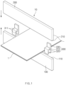
- FIG. 1 is an exploded perspective view illustrating a jig assembly for an electrode tab according to a first embodiment of the present invention
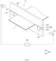
- FIG. 2 is an assembled perspective view illustrating the jig assembly for the electrode tab according to the first embodiment of the present invention
- FIG. 3 is a front view of FIG. 2
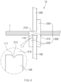
- FIG. 4 is a side view of FIG. 2 .
- the jig assembly 10 for the electrode tabs includes a first pressing member 100, a second pressing member 200, and an adjustment jig 300.
- the first pressing member 100 and the second pressing member 200 press the electrode tabs 1 to gather the electrode tabs 1 together. That is, referring to FIG. 1 , the first pressing member 100 and the second pressing member 200 has a structure, in which the first pressing member 100 and the second pressing member 200 are symmetrically provided on the uppermost and lowermost ends of the electrode tabs 1, respectively, and press the electrode tabs 1 so that the electrode tabs 1 are bundled to be gathered.
- the first pressing member 100 is disposed on the lowermost end of the electrode tabs 1, and the second pressing member 200 is disposed to be movable toward the first pressing member 100 by a hydraulic device (not shown) in a state of being disposed at the uppermost end of the electrode tabs 1.
- a hydraulic device not shown
- the electrode tabs 1 are gathered by the first and second pressing members 100 and 200.
- Each of a pressing surface 110 of the first pressing member 100 and a pressing surface 210 of the second pressing member 200, which press the electrode tabs 1, may be provided as a horizontal plane to increase in adhesion.
- the adjustment jig 300 includes an adjustment part 310.
- the adjustment part 310 is provided between the first pressing member 100 and the second pressing member 200 to support the first pressing member 100 and the second pressing member 200.
- the adjustment part 310 may be disposed between the pressing surface 110 of the first pressing member 100 and the pressing surface 210 of the second pressing member 200, and thus, the first pressing member 100 and the second pressing member 200 may be maintained to be spaced a set interval or more from each other.
- the adjustment part 310 may space the first pressing member 100 and the second pressing member 200 apart from each other so that the first pressing member 100 and the second pressing member 200 are maintained at a set distance or more, and thus, the electrode tabs pressed by the first pressing member 100 and the second pressing member 200 may be adjusted so as not to be pressed to be spaced the set interval or less from each other, thereby preventing the electrode tabs 1 from being damaged and deformed.
- the first pressing member 100 and the second pressing member 200 may be provided to be elongated in a full-width direction of the electrode tabs 1 (left and right direction when viewed in FIG. 3 ).
- the adjustment part 310 may be provided between an end of the first pressing member 100 and an end of the second pressing member 200, which extend to the outside of the electrode tabs 1.
- the adjustment part 310 may be provided between both the ends of the first pressing member 100 and both the ends of the second pressing member 200, and thus, the first pressing member 100 and the second pressing member 200 may be stably supported.
- the adjustment part 310 may have a square block shape so that the pressing surfaces 210 of the first pressing member 100 and the second pressing member 200 are in close surface contact with each other.
- the adjustment part 310 may be made of the same material as that of each of the first pressing member 100 and the second pressing member 200. Thus, it is possible to prevent the adjustment part 310 or the first pressing member 100 and the second pressing member 200 from being easily worn out.
- An adhesive layer may be further provided between the adjustment part and the first pressing member.
- adhesion between the adjustment part and the first pressing member may increase.
- a 'V'-shaped coupling groove 111 may be defined in the pressing surface 110 of the first pressing member 100 in a longitudinal direction
- a 'V'-shaped coupling protrusion 313 may be defined in the adjustment part 310 so as to be movable along the coupling groove 111. This may prevent fixing force and shaking of the adjustment part.
- the set interval may be a thickness of the adjustment part 310.
- the thickness of the adjustment part 310 may be equal to or less than a thickness of the bundled electrode tabs 1.
- the thickness of the adjustment part is less that the thickness of the bundled electrode tabs.
- the adjustment jig 300 may further include a fixing part 320.
- the fixing part 320 may be provided on each of both ends (both ends of a bottom surface of the adjustment part 310 when viewed in FIG. 1 ) of one surface of the adjustment part 310 disposed in a full-length direction of the electrode tabs 1 (i.e., the lengthwise direction of the electrode tabs) and may be supported on both surfaces of the first pressing member 100.
- the adjustment part 310 may be disposed so as not to move on the pressing surface 110 of the first pressing member 100.
- the fixing part 320 and the adjustment part 310 may be integrally provided. That is, the fixing part 320 and the adjustment part 310, which are integrated with each other, may have a " " shape. Thus, ease of the manufacture may be improved.
- the adjustment jig 300 may further include a support part 330.
- the support part 330 is provided on one end of the other surface of the adjustment part 310 (rear end of a top surface of the adjustment part 310 when viewed in FIG. 1 ) disposed in the full-length direction of the electrode tabs 1 and is supported on the second pressing member 200. That is, the support part 330 guides the second pressing member 200 to be supported on the top surface of the adjustment part 310.
- the support part 330 and the adjustment part 310 may be integrally provided. Thus, ease of the manufacture may be improved.
- the jig assembly 10 for an electrode tab according to the first embodiment of the present invention may further include an inspection member 400.
- the inspection member 400 is configured to measure the interval between the first pressing member 100 and the second pressing member 200. That is, the inspection member 400 measures the interval between the first pressure member 100 and the second pressure member 200, which are spaced apart from each other by the adjustment part 310, and if the measured interval is within a range of an input set interval, it is determined as being normal, and if the measured interval is out of the range of the set interval, it is determined as being defective.
- the inspection member 400 includes an infrared camera 410 that measures the interval between the first pressing member 100 and the second pressing member 200 and an inspection part 420 that measures the interval between the first pressing member 100 and the second pressing member 200 through an image photographed by the infrared camera 410 to inspect whether the measured interval is within the range of the input set interval.
- the jig assembly 10 for the electrode tab according to the first embodiment of the present invention may further include the inspection member 400 to easily check whether the interval between the first pressing member 100 and the second pressing member 200 is reduced below the set interval or more.
- FIG. 5 is a side view illustrating a welding device for an electrode tab according to a second embodiment of the present invention.
- a welding device for an electrode tab according to a second embodiment of the present invention has a structure including a jig assembly for an electrode tab that is described above.
- the welding device for the electrode tab includes a jig assembly for the electrode tab that presses electrode tabs 1 provided on ends of a plurality of electrodes to gather the electrode tabs 1, an anvil 20 supporting a bottom surface of a welding part in which the electrode tabs and an electrode lead 2 overlap each other, and a horn 30 disposed on a top surface of the welding part to weld the electrode tabs 1 to the electrode lead 2 using ultrasonic waves in a state of pressing the electrode tab 1 together with the anvil 20.
- the jig assembly for the electrode tab has the same configuration as the jig assembly for the electrode tab described in the first embodiment, and thus, duplicated descriptions are omitted.
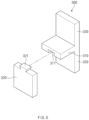
- FIG. 6 is a perspective view illustrating a jig assembly for an electrode tab according to a third embodiment of the present invention.
- a jig assembly for an electrode tab according to a third embodiment of the present invention includes an adjustment jig 300, and the adjustment jig 300 includes a fixing part 320 provided on each of both ends of a bottom surface of the adjustment part 310.
- a guide groove 311 extending toward the first pressing member 100 is defined in one end of the adjustment part 310, and a guide protrusion 321 slidably coupled to the guide groove 311 is disposed on the other fixing part 320.
- an interval between the fixing part 320 provided on each of both the ends of the adjustment part 310 and the fixing part 320 may be adjusted.
- the fixing part that is fixed in position may be fixed to the adjustment part through a fixing means such as a bolt.
- the jig assembly for the electrode tab according to the third embodiment of the present invention may be used to be compatible with the first pressing member 100 having various thicknesses.
- the adjustment jig may be compressed to the first pressing member 100 by adjusting the interval between the fixing part 320 and the fixing part 320 to prevent the adjustment jig 300 from being separated from the first pressing member 100.
- FIG. 7 is a side view illustrating a welding device for an electrode tab according to a fourth embodiment of the present invention.
- a jig assembly for an electrode tab includes an adjustment part 310 supporting a first pressing member 100 and a second pressing member 200.
- a protective film having elasticity is provided on a surface of the adjustment part 310 on which the first pressing member 100 and the second pressing member 200 are supported.
- the protective film may be made of a synthetic resin material.
- a welding device for the electrode tab may prevent impact force and noise between the first pressing member 100 and the adjustment part 310 or between the second pressing member 200 and the adjustment part 310 from occurring, and particularly, may significantly prevent abrasion from occurring.
- the protective film may have a thickness of 1 ⁇ m to 10 ⁇ m and may be replaced every set time.
- FIG. 8 is a side view illustrating a welding device for an electrode tab according to a fifth embodiment of the present invention.
- each of a first pressing member 100 and a second pressing member 200 is made of a metal material, and one surface of an adjustment part 310 (bottom surface of the adjustment part 310 when viewed in FIG. 8 ) has magnetic force to be attached to the first pressing member 100. That is, one surface of the adjustment part 310 may be provided as a magnet surface 312.
- the adjustment part 310 may be stably attached and fixed to the first pressing member 100 without a separate member.
Landscapes
- Chemical & Material Sciences (AREA)
- Chemical Kinetics & Catalysis (AREA)
- Electrochemistry (AREA)
- General Chemical & Material Sciences (AREA)
- Engineering & Computer Science (AREA)
- Mechanical Engineering (AREA)
- Physics & Mathematics (AREA)
- Optics & Photonics (AREA)
- Manufacturing & Machinery (AREA)
- Connection Of Batteries Or Terminals (AREA)
Abstract
Description
- The present application claims the benefit of the priority of
Korean Patent Application Nos. 10-2022-0019800, filed on February 15, 2022 10-2023-0014730, filed on February 03, 2023 - The present invention relates to a jig assembly for electrode tabs, which gathers the electrode tabs and a welding device for the electrode tabs, which includes the same.
- In general, secondary batteries refer to chargeable and dischargeable, unlike primary batteries that are not chargeable. The secondary batteries are being widely used for mobile phones, notebook computers, and camcorders, electric vehicles, and the like.
- The secondary batteries are classified into a can-type secondary battery, in which an electrode assembly is embedded in a metal can, and a pouch-type secondary battery in which an electrode assembly is embedded in a pouch. The can-type secondary battery includes an electrode assembly, a can accommodating the electrode assembly, and a cap assembly mounted on an opening of the can. In addition, the pouch-type secondary battery includes an electrode assembly, a pouch accommodating the electrode assembly, and an electrode lead connected to an electrode assembly and lead out of the pouch.
- Also, the electrode assembly has a structure in which a plurality of electrodes and a plurality of separators are alternately stacked, and the electrode tab is provided on an end of each of the electrodes. That is, the electrode tabs are provided at ends of the plurality of electrodes. In addition, the electrode tabs are coupled to an electrode lead in a bundled state.
- The plurality of electrodes may be a positive electrode and a negative electrode. That is, the electrode assembly has a structure in which the positive electrode and the negative electrode are alternately disposed with a separator interposed therebetween.
- Here, the electrode tabs and the electrode lead are coupled to each other through a welding device, and the welding device includes a guide jig that gathers the electrode tabs together, and a horn and anvil for welding the electrode tabs to the electrode lead. The guide jig includes first and second pressing members that press the upper and lower portions of the electrode tabs to gather the electrode tabs together.
- However, the guide jig has a problem in that the electrode tabs are damaged or deformed by pressing force of the first and second pressing members.
- According to the present invention, pressing force applied to electrode tabs may be adjusted by spacing first and second pressing members apart from each other so as to be maintained at a predetermined distance or more, thereby preventing the electrode tabs from being damaged and deformed. Particularly, an object of the present invention is to provide a jig assembly for an electrode tab, in which an interval between first and second pressing members is easily adjusted to improve work efficiency, and a welding device for the electrode tab, which includes the same.
- The present invention may relate to a jig assembly for an electrode tab, which includes: a first pressing member and a second pressing member, which are configured to press electrode tab provided on a plurality of electrode parts so that the electrode tabs are gathered to be bundled; and an adjustment jig configured to space the first pressing member and the second pressing member apart from each other so that an interval between the first pressing member and the second pressing member is maintained at a set interval or more so as to adjust pressing force applied to the electrode tabs.
- The adjustment jig may include an adjustment part provided between the first pressing member and the second pressing member to space the first pressing member and the second pressing member apart from each other so that the interval between the first pressing member and the second pressing member is maintained at the set interval or more.
- The first pressing member and the second pressing member may be provided to extend to be elongated in a full-width direction of the electrode tabs, and the adjustment part may be provided between an end of the first pressing member and an end of the second pressing member, which extend to the outside of the electrode tabs.
- A pressing surface of each of the first pressing member and the second pressing member, which press the electrode tabs, may be provided as a horizontal plane, and the adjustment part may have a square block shape to be in close surface contact with the pressing surface of each of the first pressing member and the second pressing member.
- The set interval may be a thickness of the adjustment part, and the thickness of the adjustment part may be less than that of the bundled electrode tabs.
- The adjustment jig may further include a fixing part provided on each of both ends of one surface of the adjustment part disposed in a full-length direction of the electrode tabs to support each of both surfaces of the first pressing member.
- The fixing part and the adjustment part may be provided to be integrated with each other.
- One fixing part of the fixing parts may be integrally provided on an end of one side of the adjustment part, and the other fixing part may be coupled to an end of the other side of the adjustment part so as to be slidably movable toward the first pressing member.
- A guide groove extending toward the first pressing member may be defined in an end of one side of the adjustment part, and a guide protrusion slidably coupled to the guide groove may be disposed on the other fixing part.
- The adjustment jig may further include a support part provided on one end of the other surface of the adjustment part disposed in a full-length direction of the electrode tabs so as to be supported on a surface of the second pressing member.
- The support part and the adjustment part may be provided to be integrated with each other.
- A protective film having elasticity may be further provided on a surface of the adjustment part on which the first pressing member and the second pressing member are supported.
- Each of the first pressing member and the second pressing member may be made of a metal material, and one surface of the adjustment part may have magnetism to be attached to the first pressing member.
- The jig assembly for the electrode tab may further include an inspection member configured to measure an interval between the first pressing member and the second pressing member, which are spaced apart from each other by the adjustment part, wherein, if the measured interval is within a range of an input set interval, it may be determined as being normal, and if the measured interval is out of the range of the set interval, it may be determined as being defective.
- A welding device for an electrode tab according to the present invention may include the jig assembly for the electrode tab.
- The jig assembly for the electrode tab according to the present invention may include the adjustment jig so that the interval between the first and second pressing members are spaced apart from each other so as to be maintained at the set distance or more from, and thus, the pressing force applied to the electrode tabs may be adjusted to prevent the electrode tabs from being damaged and deformed. Particularly, since the interval between the first and second pressing members may be easily adjusted to improve the work efficiency.
-
-
FIG. 1 is an exploded perspective view illustrating a jig assembly for an electrode tab according to a first embodiment of the present invention. -
FIG. 2 is an assembled perspective view illustrating the jig assembly for the electrode tab according to the first embodiment of the present invention. -
FIG. 3 is a front view ofFIG. 2 . -
FIG. 4 is a side view ofFIG. 2 . -
FIG. 5 is a side view illustrating a welding device for an electrode tab according to a second embodiment of the present invention. -
FIG. 6 is a perspective view illustrating a jig assembly for an electrode tab according to a third embodiment of the present invention. -
FIG. 7 is a side view illustrating a welding device for an electrode tab according to a fourth embodiment of the present invention. -
FIG. 8 is a side view illustrating a welding device for an electrode tab according to a fifth embodiment of the present invention. - Hereinafter, embodiments of the present invention will be described in detail with reference to the accompanying drawings in such a manner that the technical idea of the present invention may easily be carried out by a person with ordinary skill in the art to which the invention pertains. The present invention may, however, be embodied in different forms and should not be construed as limited to the embodiments set forth herein. In the drawings, anything unnecessary for describing the present invention will be omitted for clarity, and also like reference numerals in the drawings denote like elements.
- A secondary battery includes an electrode assembly and a pouch accommodating the electrode assembly. The electrode assembly has a structure in which a plurality of electrodes and a plurality of separators are alternately disposed. In addition, the pouch includes an accommodation part accommodating the electrode assembly and a sealing part sealing the accommodation part.
- The plurality of electrodes may be positive and negative electrodes. That is, the electrode assembly has a structure in which the positive electrode and the negative electrode are alternately disposed with a separator interposed therebetween.
- Referring to
FIG. 1 , an electrode tab is provided on an end of the electrode. That is, a plurality of electrode tabs 1 (hereinafter, referred to as electrode tabs) are provided on ends of the plurality of electrodes. In addition, theelectrode leads 2 are coupled to theelectrode tabs 1. - Here, in order to couple the electrode tabs to the
electrode lead 2, theelectrode tabs 1 have to be gathered together, and at this time, thejig assembly 10 for the electrode tabs according to the first embodiment of the present invention is used. -
FIG. 1 is an exploded perspective view illustrating a jig assembly for an electrode tab according to a first embodiment of the present invention,FIG. 2 is an assembled perspective view illustrating the jig assembly for the electrode tab according to the first embodiment of the present invention,FIG. 3 is a front view ofFIG. 2 , andFIG. 4 is a side view ofFIG. 2 . - As illustrated in
FIGS. 1 to 4 , ajig assembly 10 for electrode tabs according to a first embodiment of the present invention is configured to gatherelectrode tabs 1 provided on ends of a plurality of electrodes. - That is, the
jig assembly 10 for the electrode tabs according to the first embodiment of the present invention includes a first pressingmember 100, a secondpressing member 200, and anadjustment jig 300. - The first
pressing member 100 and the second pressingmember 200 press theelectrode tabs 1 to gather theelectrode tabs 1 together. That is, referring toFIG. 1 , the first pressingmember 100 and the second pressingmember 200 has a structure, in which the first pressingmember 100 and the second pressingmember 200 are symmetrically provided on the uppermost and lowermost ends of theelectrode tabs 1, respectively, and press theelectrode tabs 1 so that theelectrode tabs 1 are bundled to be gathered. - For example, the first pressing
member 100 is disposed on the lowermost end of theelectrode tabs 1, and the second pressingmember 200 is disposed to be movable toward the first pressingmember 100 by a hydraulic device (not shown) in a state of being disposed at the uppermost end of theelectrode tabs 1. Thus, theelectrode tabs 1 are gathered by the first and secondpressing members - Each of a
pressing surface 110 of the first pressingmember 100 and apressing surface 210 of the second pressingmember 200, which press theelectrode tabs 1, may be provided as a horizontal plane to increase in adhesion. - The
adjustment jig 300 spaces the first pressingmember 100 and the second pressingmember 200 apart from each other so that the first pressingmember 100 and the second pressingmember 200 are maintained at a set interval or more, thereby adjusting pressing force applied to theelectrode tabs 1. In other words, the adjustment jig may space the first pressingmember 100 and the second pressingmember 200 so that the first pressingmember 100 and the second pressingmember 200 is not spaced a set interval or less from each other. - For example, the
adjustment jig 300 includes anadjustment part 310. Theadjustment part 310 is provided between the first pressingmember 100 and the second pressingmember 200 to support the first pressingmember 100 and the second pressingmember 200. - That is, the
adjustment part 310 may be disposed between thepressing surface 110 of the first pressingmember 100 and thepressing surface 210 of the second pressingmember 200, and thus, the first pressingmember 100 and the second pressingmember 200 may be maintained to be spaced a set interval or more from each other. In other words, theadjustment part 310 may space the first pressingmember 100 and the second pressingmember 200 apart from each other so that the first pressingmember 100 and the second pressingmember 200 are maintained at a set distance or more, and thus, the electrode tabs pressed by the first pressingmember 100 and the second pressingmember 200 may be adjusted so as not to be pressed to be spaced the set interval or less from each other, thereby preventing theelectrode tabs 1 from being damaged and deformed. - The first
pressing member 100 and the second pressingmember 200 may be provided to be elongated in a full-width direction of the electrode tabs 1 (left and right direction when viewed inFIG. 3 ). In addition, theadjustment part 310 may be provided between an end of the first pressingmember 100 and an end of the second pressingmember 200, which extend to the outside of theelectrode tabs 1. Thus, it is possible to prevent an interference between theadjustment part 310 and theelectrode tabs 1, and as a result, it is possible to prevent an electrode tab part from being damaged by theadjustment part 310. Particularly, theadjustment part 310 may be provided between both the ends of the first pressingmember 100 and both the ends of the second pressingmember 200, and thus, the first pressingmember 100 and the second pressingmember 200 may be stably supported. - The
adjustment part 310 may have a square block shape so that thepressing surfaces 210 of the first pressingmember 100 and the second pressingmember 200 are in close surface contact with each other. Particularly, theadjustment part 310 may be made of the same material as that of each of the first pressingmember 100 and the second pressingmember 200. Thus, it is possible to prevent theadjustment part 310 or the first pressingmember 100 and the second pressingmember 200 from being easily worn out. - An adhesive layer may be further provided between the adjustment part and the first pressing member. Thus, adhesion between the adjustment part and the first pressing member may increase. Referring to the enlarged view of
FIG. 4 , a 'V'-shapedcoupling groove 111 may be defined in thepressing surface 110 of the first pressingmember 100 in a longitudinal direction, and a 'V'-shapedcoupling protrusion 313 may be defined in theadjustment part 310 so as to be movable along thecoupling groove 111. This may prevent fixing force and shaking of the adjustment part. - The set interval may be a thickness of the
adjustment part 310. In addition, the thickness of theadjustment part 310 may be equal to or less than a thickness of the bundledelectrode tabs 1. Preferably, the thickness of the adjustment part is less that the thickness of the bundled electrode tabs. Thus, theelectrode tabs 1 may be effectively pressed by the first pressingmember 100 and the second pressingmember 200, and thus, theelectrode tabs 1 may be gathered to be bundled. - The
adjustment jig 300 may further include a fixingpart 320. The fixingpart 320 may be provided on each of both ends (both ends of a bottom surface of theadjustment part 310 when viewed inFIG. 1 ) of one surface of theadjustment part 310 disposed in a full-length direction of the electrode tabs 1 (i.e., the lengthwise direction of the electrode tabs) and may be supported on both surfaces of the first pressingmember 100. Thus, theadjustment part 310 may be disposed so as not to move on thepressing surface 110 of the first pressingmember 100. - The fixing
part 320 and theadjustment part 310 may be integrally provided. That is, the fixingpart 320 and theadjustment part 310, which are integrated with each other, may have a "" shape. Thus, ease of the manufacture may be improved.
- The
adjustment jig 300 may further include asupport part 330. Thesupport part 330 is provided on one end of the other surface of the adjustment part 310 (rear end of a top surface of theadjustment part 310 when viewed inFIG. 1 ) disposed in the full-length direction of theelectrode tabs 1 and is supported on the second pressingmember 200. That is, thesupport part 330 guides the second pressingmember 200 to be supported on the top surface of theadjustment part 310. - The
support part 330 and theadjustment part 310 may be integrally provided. Thus, ease of the manufacture may be improved. - Therefore, the
jig assembly 10 for the electrode tabs according to the first embodiment of the present invention may adjust the pressing force applied to theelectrode tabs 1 by providing theadjustment jig 300, and as a result, theelectrode tabs 1 may be prevented from being damaged and deformed. Particularly, since the interval between the first and secondpressing members 200 may be easily adjusted to improve the work efficiency. - The
jig assembly 10 for an electrode tab according to the first embodiment of the present invention may further include an inspection member 400. - Referring to
FIG. 2 , the inspection member 400 is configured to measure the interval between the first pressingmember 100 and the second pressingmember 200. That is, the inspection member 400 measures the interval between thefirst pressure member 100 and thesecond pressure member 200, which are spaced apart from each other by theadjustment part 310, and if the measured interval is within a range of an input set interval, it is determined as being normal, and if the measured interval is out of the range of the set interval, it is determined as being defective. - The inspection member 400 includes an
infrared camera 410 that measures the interval between the first pressingmember 100 and the second pressingmember 200 and aninspection part 420 that measures the interval between the first pressingmember 100 and the second pressingmember 200 through an image photographed by theinfrared camera 410 to inspect whether the measured interval is within the range of the input set interval. - Therefore, the
jig assembly 10 for the electrode tab according to the first embodiment of the present invention may further include the inspection member 400 to easily check whether the interval between the first pressingmember 100 and the second pressingmember 200 is reduced below the set interval or more. - Hereinafter, in describing another embodiment of the present invention, the same reference numerals are used for the same components as those of the above-described embodiment, and duplicated descriptions will be omitted.
-
FIG. 5 is a side view illustrating a welding device for an electrode tab according to a second embodiment of the present invention. - A welding device for an electrode tab according to a second embodiment of the present invention has a structure including a jig assembly for an electrode tab that is described above.
- For example, as illustrated in
FIG. 5 , the welding device for the electrode tab according to the second embodiment of the present invention includes a jig assembly for the electrode tab that presseselectrode tabs 1 provided on ends of a plurality of electrodes to gather theelectrode tabs 1, ananvil 20 supporting a bottom surface of a welding part in which the electrode tabs and anelectrode lead 2 overlap each other, and ahorn 30 disposed on a top surface of the welding part to weld theelectrode tabs 1 to theelectrode lead 2 using ultrasonic waves in a state of pressing theelectrode tab 1 together with theanvil 20. - The jig assembly for the electrode tab has the same configuration as the jig assembly for the electrode tab described in the first embodiment, and thus, duplicated descriptions are omitted.
- Therefore, the welding device for electrode tab according to the second embodiment of the present invention may stably weld the electrode tabs to the
electrode lead 2 without damaging or deforming theelectrode tabs 1. -
FIG. 6 is a perspective view illustrating a jig assembly for an electrode tab according to a third embodiment of the present invention. - A jig assembly for an electrode tab according to a third embodiment of the present invention includes an
adjustment jig 300, and theadjustment jig 300 includes a fixingpart 320 provided on each of both ends of a bottom surface of theadjustment part 310. - Here, one fixing
part 320 of the fixingparts 320 is integrally provided on one end of anadjustment part 310, and the other fixingpart 320 is coupled to the other end of theadjustment part 310. Here, the other fixingpart 320 is coupled to be slidably movable toward the first pressingmember 100. - For example, a
guide groove 311 extending toward the first pressingmember 100 is defined in one end of theadjustment part 310, and aguide protrusion 321 slidably coupled to theguide groove 311 is disposed on the other fixingpart 320. Thus, an interval between the fixingpart 320 provided on each of both the ends of theadjustment part 310 and the fixingpart 320 may be adjusted. The fixing part that is fixed in position may be fixed to the adjustment part through a fixing means such as a bolt. - Therefore, the jig assembly for the electrode tab according to the third embodiment of the present invention may be used to be compatible with the first pressing
member 100 having various thicknesses. Particularly, the adjustment jig may be compressed to the first pressingmember 100 by adjusting the interval between the fixingpart 320 and the fixingpart 320 to prevent theadjustment jig 300 from being separated from the first pressingmember 100. -
FIG. 7 is a side view illustrating a welding device for an electrode tab according to a fourth embodiment of the present invention. - As illustrated in
FIG. 7 , a jig assembly for an electrode tab according to a fourth embodiment of the present invention includes anadjustment part 310 supporting a first pressingmember 100 and a secondpressing member 200. - Here, a protective film having elasticity is provided on a surface of the
adjustment part 310 on which the first pressingmember 100 and the second pressingmember 200 are supported. The protective film may be made of a synthetic resin material. - Therefore, a welding device for the electrode tab according to the fourth embodiment of the present invention may prevent impact force and noise between the first pressing
member 100 and theadjustment part 310 or between the second pressingmember 200 and theadjustment part 310 from occurring, and particularly, may significantly prevent abrasion from occurring. - The protective film may have a thickness of 1 µm to 10 µm and may be replaced every set time.
-
FIG. 8 is a side view illustrating a welding device for an electrode tab according to a fifth embodiment of the present invention. - As illustrated in
FIG. 8 , in a jig assembly for an electrode tab according to a fifth embodiment of the present invention, each of a first pressingmember 100 and a secondpressing member 200 is made of a metal material, and one surface of an adjustment part 310 (bottom surface of theadjustment part 310 when viewed inFIG. 8 ) has magnetic force to be attached to the first pressingmember 100. That is, one surface of theadjustment part 310 may be provided as amagnet surface 312. - Therefore, in the welding device for the electrode tab according to the fifth embodiment of the present invention, the
adjustment part 310 may be stably attached and fixed to the first pressingmember 100 without a separate member. - Accordingly, the scope of the present invention is defined by the appended claims more than the foregoing description and the exemplary embodiments described therein. Various modifications made within the meaning of an equivalent of the claims of the invention and within the claims are to be regarded to be in the scope of the present invention.
-
- 1: Electrode tab
- 2: Electrode lead
- 10: Jig assembly for electrode tab
- 20: Anvil
- 30: Horn
- 100: First pressing member
- 110: Pressing surface
- 111: Coupling groove
- 200: Second pressing member
- 210: Pressing surface
- 300: Adjustment jig
- 310: Adjustment part
- 311: Guide groove
- 312: Magnet surface
- 313: Coupling protrusion
- 320: Fixing part
- 321: Guide protrusion
- 330: Support part
- 400: Inspection member
Claims (15)
- A jig assembly for an electrode tab, comprising:a first pressing member and a second pressing member, which are configured to press electrode tab provided on a plurality of electrode parts so that the electrode tabs are gathered to be bundled; andan adjustment jig configured to space the first pressing member and the second pressing member apart from each other so that an interval between the first pressing member and the second pressing member is maintained at a set interval or more so as to adjust pressing force applied to the electrode tabs.
- The jig assembly for the electrode tab of claim 1, wherein the adjustment jig comprises an adjustment part provided between the first pressing member and the second pressing member to space the first pressing member and the second pressing member apart from each other so that the interval between the first pressing member and the second pressing member is maintained at the set interval or more.
- The jig assembly for the electrode tab of claim 2, wherein the first pressing member and the second pressing member are provided to extend to be elongated in a full-width direction of the electrode tabs, and
the adjustment part is provided between an end of the first pressing member and an end of the second pressing member, which extend to the outside of the electrode tabs. - The jig assembly for the electrode tab of claim 2, wherein a pressing surface of each of the first pressing member and the second pressing member, which press the electrode tabs, is provided as a horizontal plane, and
the adjustment part has a square block shape to be in close surface contact with the pressing surface of each of the first pressing member and the second pressing member. - The jig assembly for the electrode tab of claim 2, wherein the set interval is a thickness of the adjustment part, and
the thickness of the adjustment part is less than that of the bundled electrode tabs. - The jig assembly for the electrode tab of claim 2, wherein the adjustment jig further comprises a fixing part provided on each of both ends of one surface of the adjustment part disposed in a full-length direction of the electrode tabs to support each of both surfaces of the first pressing member.
- The jig assembly for the electrode tab of claim 6, wherein the fixing part and the adjustment part are provided to be integrated with each other.
- The jig assembly for the electrode tab of claim 6, wherein one fixing part of the fixing parts is integrally provided on an end of one side of the adjustment part, and the other fixing part is coupled to an end of the other side of the adjustment part so as to be slidably movable toward the first pressing member.
- The jig assembly for the electrode tab of claim 8, wherein a guide groove extending toward the first pressing member is defined in an end of one side of the adjustment part, and
a guide protrusion slidably coupled to the guide groove is disposed on the other fixing part. - The jig assembly for the electrode tab of claim 2, wherein the adjustment jig further comprises a support part provided on one end of the other surface of the adjustment part disposed in a full-length direction of the electrode tabs so as to be supported on a surface of the second pressing member.
- The jig assembly for the electrode tab of claim 10, wherein the support part and the adjustment part are provided to be integrated with each other.
- The jig assembly for the electrode tab of claim 2, further comprising a protective film having elasticity is further provided on a surface of the adjustment part on which the first pressing member and the second pressing member are supported.
- The jig assembly for the electrode tab of claim 2, wherein each of the first pressing member and the second pressing member is made of a metal material, and
one surface of the adjustment part has magnetism to be attached to the first pressing member. - The jig assembly for the electrode tab of claim 2, wherein the jig assembly for the electrode tab further comprises an inspection member configured to measure an interval between the first pressing member and the second pressing member, which are spaced apart from each other by the adjustment part,
wherein, if the measured interval is within a range of an input set interval, it is determined as being normal, and if the measured interval is out of the range of the set interval, it is determined as being defective. - A welding device for an electrode tab, comprising the jig assembly for the electrode tab of claim 1.
Applications Claiming Priority (3)
| Application Number | Priority Date | Filing Date | Title |
|---|---|---|---|
| KR20220019800 | 2022-02-15 | ||
| KR1020230014730A KR20230122984A (en) | 2022-02-15 | 2023-02-03 | Jig assembly for electrode tab and welding apparatus for electrode tab including the same |
| PCT/KR2023/001944 WO2023158157A1 (en) | 2022-02-15 | 2023-02-09 | Electrode tab jig assembly and electrode tab welding device comprising same |
Publications (3)
| Publication Number | Publication Date |
|---|---|
| EP4481934A1 true EP4481934A1 (en) | 2024-12-25 |
| EP4481934A4 EP4481934A4 (en) | 2025-06-11 |
| EP4481934B1 EP4481934B1 (en) | 2026-04-01 |
Family
ID=87578564
Family Applications (1)
| Application Number | Title | Priority Date | Filing Date |
|---|---|---|---|
| EP23756570.0A Active EP4481934B1 (en) | 2022-02-15 | 2023-02-09 | Electrode tab jig assembly and electrode tab welding device comprising same |
Country Status (4)
| Country | Link |
|---|---|
| US (1) | US20250114881A1 (en) |
| EP (1) | EP4481934B1 (en) |
| JP (1) | JP7749909B2 (en) |
| WO (1) | WO2023158157A1 (en) |
Family Cites Families (9)
| Publication number | Priority date | Publication date | Assignee | Title |
|---|---|---|---|---|
| KR101763980B1 (en) * | 2013-08-30 | 2017-08-01 | 주식회사 엘지화학 | Sealiing tool of pouch type secondary battery |
| KR102234993B1 (en) * | 2016-12-21 | 2021-04-01 | 주식회사 엘지화학 | Battery Cell and Manufacturing Method thereof |
| KR102647221B1 (en) * | 2016-12-22 | 2024-03-14 | 에스케이온 주식회사 | Sealing Device for Secondary Battery |
| KR102105665B1 (en) * | 2018-04-04 | 2020-05-29 | 주식회사 엘지화학 | A pressing jig for pressing a bus bar and a battery module manufacturing system comprising the same |
| JP2019207794A (en) * | 2018-05-29 | 2019-12-05 | 株式会社豊田自動織機 | Method for manufacturing power storage device |
| KR102043114B1 (en) * | 2019-04-25 | 2019-11-27 | 백영진 | Welding guide device for electrode lead of secondary battery cell and welding guide system using the same |
| US10862712B1 (en) | 2019-06-17 | 2020-12-08 | Savant Systems, Inc. | Battery-assisted power-over-ethernet powered device |
| CN113880809B (en) | 2020-07-03 | 2022-10-18 | 盛世泰科生物医药技术(苏州)有限公司 | Pyrimidine derivative and preparation method and application thereof |
| KR102716986B1 (en) * | 2020-07-20 | 2024-10-15 | 주식회사 엘지에너지솔루션 | Ultrasonic welding device and method for secondary battery |
-
2023
- 2023-02-09 EP EP23756570.0A patent/EP4481934B1/en active Active
- 2023-02-09 JP JP2024543279A patent/JP7749909B2/en active Active
- 2023-02-09 US US18/726,211 patent/US20250114881A1/en active Pending
- 2023-02-09 WO PCT/KR2023/001944 patent/WO2023158157A1/en not_active Ceased
Also Published As
| Publication number | Publication date |
|---|---|
| JP7749909B2 (en) | 2025-10-07 |
| EP4481934B1 (en) | 2026-04-01 |
| JP2025503776A (en) | 2025-02-04 |
| WO2023158157A1 (en) | 2023-08-24 |
| EP4481934A4 (en) | 2025-06-11 |
| US20250114881A1 (en) | 2025-04-10 |
Similar Documents
| Publication | Publication Date | Title |
|---|---|---|
| EP2337106B1 (en) | Rechargeable battery | |
| CN110998902B (en) | Battery module and method of manufacturing the same | |
| KR102303828B1 (en) | Flexible electrochemical device including electrode assemblies electrically connected to each other | |
| US8771863B2 (en) | Battery module and manufacturing method of battery module | |
| KR102249894B1 (en) | Rechargeable battery | |
| US20250353102A1 (en) | Electrode Tab Welding Device, Electrode Tab Welding Method, and Electrode Assembly | |
| CN111373589B (en) | Electrode assembly having improved safety in use by outermost electrode structure and current collector material, and lithium ion secondary battery having the same | |
| CN103443958B (en) | Battery pack | |
| US9431636B2 (en) | Rechargeable battery | |
| JP7767572B2 (en) | Voltage detection device and battery module | |
| US20200287195A1 (en) | Metal tab for flexible battery | |
| KR102161627B1 (en) | Secondary battery | |
| KR20160109947A (en) | Rechargeable battery | |
| EP3386019B1 (en) | Secondary battery | |
| EP4481934A1 (en) | Electrode tab jig assembly and electrode tab welding device comprising same | |
| US20210288365A1 (en) | Rechargeable battery | |
| JPWO2018163479A1 (en) | Battery pack and method of manufacturing battery pack | |
| KR20230122984A (en) | Jig assembly for electrode tab and welding apparatus for electrode tab including the same | |
| JPWO2018163481A1 (en) | Battery pack and method of manufacturing battery pack | |
| US9123947B2 (en) | Secondary battery | |
| US20070009792A1 (en) | Battery | |
| US20070037052A1 (en) | Battery module and method of making the same | |
| KR20190060963A (en) | Secondary battery | |
| CN118402133A (en) | Clamp assembly for electrode tab and welding device for electrode tab comprising same | |
| EP4614629A1 (en) | Battery pack |
Legal Events
| Date | Code | Title | Description |
|---|---|---|---|
| STAA | Information on the status of an ep patent application or granted ep patent |
Free format text: STATUS: THE INTERNATIONAL PUBLICATION HAS BEEN MADE |
|
| PUAI | Public reference made under article 153(3) epc to a published international application that has entered the european phase |
Free format text: ORIGINAL CODE: 0009012 |
|
| STAA | Information on the status of an ep patent application or granted ep patent |
Free format text: STATUS: REQUEST FOR EXAMINATION WAS MADE |
|
| 17P | Request for examination filed |
Effective date: 20240613 |
|
| AK | Designated contracting states |
Kind code of ref document: A1 Designated state(s): AL AT BE BG CH CY CZ DE DK EE ES FI FR GB GR HR HU IE IS IT LI LT LU LV MC ME MK MT NL NO PL PT RO RS SE SI SK SM TR |
|
| DAV | Request for validation of the european patent (deleted) | ||
| DAX | Request for extension of the european patent (deleted) | ||
| A4 | Supplementary search report drawn up and despatched |
Effective date: 20250513 |
|
| RIC1 | Information provided on ipc code assigned before grant |
Ipc: H01M 50/54 20210101ALI20250507BHEP Ipc: H01M 50/536 20210101ALI20250507BHEP Ipc: B23K 101/38 20060101ALI20250507BHEP Ipc: H01M 10/04 20060101ALI20250507BHEP Ipc: H01M 50/566 20210101ALI20250507BHEP Ipc: H01M 50/557 20210101ALI20250507BHEP Ipc: H01M 50/543 20210101ALI20250507BHEP Ipc: B23K 37/04 20060101ALI20250507BHEP Ipc: B23K 20/10 20060101ALI20250507BHEP Ipc: H01M 50/564 20210101AFI20250507BHEP |
|
| GRAP | Despatch of communication of intention to grant a patent |
Free format text: ORIGINAL CODE: EPIDOSNIGR1 |
|
| STAA | Information on the status of an ep patent application or granted ep patent |
Free format text: STATUS: GRANT OF PATENT IS INTENDED |
|
| RIC1 | Information provided on ipc code assigned before grant |
Ipc: H01M 50/564 20210101AFI20250828BHEP Ipc: B23K 20/10 20060101ALI20250828BHEP Ipc: B23K 37/04 20060101ALI20250828BHEP Ipc: H01M 50/543 20210101ALI20250828BHEP Ipc: H01M 50/557 20210101ALI20250828BHEP Ipc: H01M 50/566 20210101ALI20250828BHEP Ipc: H01M 10/04 20060101ALI20250828BHEP Ipc: B23K 101/38 20060101ALI20250828BHEP Ipc: H01M 50/536 20210101ALI20250828BHEP Ipc: H01M 50/54 20210101ALI20250828BHEP |
|
| INTG | Intention to grant announced |
Effective date: 20250910 |
|
| P01 | Opt-out of the competence of the unified patent court (upc) registered |
Free format text: CASE NUMBER: UPC_APP_9452_4481934/2025 Effective date: 20251009 |
|
| GRAS | Grant fee paid |
Free format text: ORIGINAL CODE: EPIDOSNIGR3 |
|
| GRAA | (expected) grant |
Free format text: ORIGINAL CODE: 0009210 |
|
| STAA | Information on the status of an ep patent application or granted ep patent |
Free format text: STATUS: THE PATENT HAS BEEN GRANTED |
|
| AK | Designated contracting states |
Kind code of ref document: B1 Designated state(s): AL AT BE BG CH CY CZ DE DK EE ES FI FR GB GR HR HU IE IS IT LI LT LU LV MC ME MK MT NL NO PL PT RO RS SE SI SK SM TR |
|
| REG | Reference to a national code |
Ref country code: CH Ref legal event code: F10 Free format text: ST27 STATUS EVENT CODE: U-0-0-F10-F00 (AS PROVIDED BY THE NATIONAL OFFICE) Effective date: 20260401 Ref country code: GB Ref legal event code: FG4D |
|
| REG | Reference to a national code |
Ref country code: IE Ref legal event code: FG4D |
|
| REG | Reference to a national code |
Ref country code: DE Ref legal event code: R096 Ref document number: 602023014590 Country of ref document: DE |