EP4481914A1 - Rack assembly and battery pack including the same - Google Patents
Rack assembly and battery pack including the same Download PDFInfo
- Publication number
- EP4481914A1 EP4481914A1 EP24166376.4A EP24166376A EP4481914A1 EP 4481914 A1 EP4481914 A1 EP 4481914A1 EP 24166376 A EP24166376 A EP 24166376A EP 4481914 A1 EP4481914 A1 EP 4481914A1
- Authority
- EP
- European Patent Office
- Prior art keywords
- tray
- rack
- bus bar
- battery cells
- deck
- Prior art date
- Legal status (The legal status is an assumption and is not a legal conclusion. Google has not performed a legal analysis and makes no representation as to the accuracy of the status listed.)
- Pending
Links
Images







Classifications
-
- H—ELECTRICITY
- H01—ELECTRIC ELEMENTS
- H01M—PROCESSES OR MEANS, e.g. BATTERIES, FOR THE DIRECT CONVERSION OF CHEMICAL ENERGY INTO ELECTRICAL ENERGY
- H01M50/00—Constructional details or processes of manufacture of the non-active parts of electrochemical cells other than fuel cells, e.g. hybrid cells
- H01M50/20—Mountings; Secondary casings or frames; Racks, modules or packs; Suspension devices; Shock absorbers; Transport or carrying devices; Holders
- H01M50/204—Racks, modules or packs for multiple batteries or multiple cells
-
- H—ELECTRICITY
- H01—ELECTRIC ELEMENTS
- H01M—PROCESSES OR MEANS, e.g. BATTERIES, FOR THE DIRECT CONVERSION OF CHEMICAL ENERGY INTO ELECTRICAL ENERGY
- H01M50/00—Constructional details or processes of manufacture of the non-active parts of electrochemical cells other than fuel cells, e.g. hybrid cells
- H01M50/20—Mountings; Secondary casings or frames; Racks, modules or packs; Suspension devices; Shock absorbers; Transport or carrying devices; Holders
- H01M50/244—Secondary casings; Racks; Suspension devices; Carrying devices; Holders characterised by their mounting method
-
- H—ELECTRICITY
- H01—ELECTRIC ELEMENTS
- H01M—PROCESSES OR MEANS, e.g. BATTERIES, FOR THE DIRECT CONVERSION OF CHEMICAL ENERGY INTO ELECTRICAL ENERGY
- H01M50/00—Constructional details or processes of manufacture of the non-active parts of electrochemical cells other than fuel cells, e.g. hybrid cells
- H01M50/20—Mountings; Secondary casings or frames; Racks, modules or packs; Suspension devices; Shock absorbers; Transport or carrying devices; Holders
- H01M50/204—Racks, modules or packs for multiple batteries or multiple cells
- H01M50/207—Racks, modules or packs for multiple batteries or multiple cells characterised by their shape
- H01M50/209—Racks, modules or packs for multiple batteries or multiple cells characterised by their shape adapted for prismatic or rectangular cells
-
- H—ELECTRICITY
- H01—ELECTRIC ELEMENTS
- H01M—PROCESSES OR MEANS, e.g. BATTERIES, FOR THE DIRECT CONVERSION OF CHEMICAL ENERGY INTO ELECTRICAL ENERGY
- H01M50/00—Constructional details or processes of manufacture of the non-active parts of electrochemical cells other than fuel cells, e.g. hybrid cells
- H01M50/20—Mountings; Secondary casings or frames; Racks, modules or packs; Suspension devices; Shock absorbers; Transport or carrying devices; Holders
- H01M50/249—Mountings; Secondary casings or frames; Racks, modules or packs; Suspension devices; Shock absorbers; Transport or carrying devices; Holders specially adapted for aircraft or vehicles, e.g. cars or trains
-
- H—ELECTRICITY
- H01—ELECTRIC ELEMENTS
- H01M—PROCESSES OR MEANS, e.g. BATTERIES, FOR THE DIRECT CONVERSION OF CHEMICAL ENERGY INTO ELECTRICAL ENERGY
- H01M50/00—Constructional details or processes of manufacture of the non-active parts of electrochemical cells other than fuel cells, e.g. hybrid cells
- H01M50/20—Mountings; Secondary casings or frames; Racks, modules or packs; Suspension devices; Shock absorbers; Transport or carrying devices; Holders
- H01M50/251—Mountings; Secondary casings or frames; Racks, modules or packs; Suspension devices; Shock absorbers; Transport or carrying devices; Holders specially adapted for stationary devices, e.g. power plant buffering or backup power supplies
-
- H—ELECTRICITY
- H01—ELECTRIC ELEMENTS
- H01M—PROCESSES OR MEANS, e.g. BATTERIES, FOR THE DIRECT CONVERSION OF CHEMICAL ENERGY INTO ELECTRICAL ENERGY
- H01M50/00—Constructional details or processes of manufacture of the non-active parts of electrochemical cells other than fuel cells, e.g. hybrid cells
- H01M50/20—Mountings; Secondary casings or frames; Racks, modules or packs; Suspension devices; Shock absorbers; Transport or carrying devices; Holders
- H01M50/258—Modular batteries; Casings provided with means for assembling
-
- H—ELECTRICITY
- H01—ELECTRIC ELEMENTS
- H01M—PROCESSES OR MEANS, e.g. BATTERIES, FOR THE DIRECT CONVERSION OF CHEMICAL ENERGY INTO ELECTRICAL ENERGY
- H01M50/00—Constructional details or processes of manufacture of the non-active parts of electrochemical cells other than fuel cells, e.g. hybrid cells
- H01M50/20—Mountings; Secondary casings or frames; Racks, modules or packs; Suspension devices; Shock absorbers; Transport or carrying devices; Holders
- H01M50/289—Mountings; Secondary casings or frames; Racks, modules or packs; Suspension devices; Shock absorbers; Transport or carrying devices; Holders characterised by spacing elements or positioning means within frames, racks or packs
-
- H—ELECTRICITY
- H01—ELECTRIC ELEMENTS
- H01M—PROCESSES OR MEANS, e.g. BATTERIES, FOR THE DIRECT CONVERSION OF CHEMICAL ENERGY INTO ELECTRICAL ENERGY
- H01M50/00—Constructional details or processes of manufacture of the non-active parts of electrochemical cells other than fuel cells, e.g. hybrid cells
- H01M50/20—Mountings; Secondary casings or frames; Racks, modules or packs; Suspension devices; Shock absorbers; Transport or carrying devices; Holders
- H01M50/289—Mountings; Secondary casings or frames; Racks, modules or packs; Suspension devices; Shock absorbers; Transport or carrying devices; Holders characterised by spacing elements or positioning means within frames, racks or packs
- H01M50/291—Mountings; Secondary casings or frames; Racks, modules or packs; Suspension devices; Shock absorbers; Transport or carrying devices; Holders characterised by spacing elements or positioning means within frames, racks or packs characterised by their shape
-
- H—ELECTRICITY
- H01—ELECTRIC ELEMENTS
- H01M—PROCESSES OR MEANS, e.g. BATTERIES, FOR THE DIRECT CONVERSION OF CHEMICAL ENERGY INTO ELECTRICAL ENERGY
- H01M50/00—Constructional details or processes of manufacture of the non-active parts of electrochemical cells other than fuel cells, e.g. hybrid cells
- H01M50/50—Current conducting connections for cells or batteries
- H01M50/502—Interconnectors for connecting terminals of adjacent batteries; Interconnectors for connecting cells outside a battery casing
-
- H—ELECTRICITY
- H01—ELECTRIC ELEMENTS
- H01M—PROCESSES OR MEANS, e.g. BATTERIES, FOR THE DIRECT CONVERSION OF CHEMICAL ENERGY INTO ELECTRICAL ENERGY
- H01M50/00—Constructional details or processes of manufacture of the non-active parts of electrochemical cells other than fuel cells, e.g. hybrid cells
- H01M50/50—Current conducting connections for cells or batteries
- H01M50/502—Interconnectors for connecting terminals of adjacent batteries; Interconnectors for connecting cells outside a battery casing
- H01M50/503—Interconnectors for connecting terminals of adjacent batteries; Interconnectors for connecting cells outside a battery casing characterised by the shape of the interconnectors
-
- H—ELECTRICITY
- H01—ELECTRIC ELEMENTS
- H01M—PROCESSES OR MEANS, e.g. BATTERIES, FOR THE DIRECT CONVERSION OF CHEMICAL ENERGY INTO ELECTRICAL ENERGY
- H01M50/00—Constructional details or processes of manufacture of the non-active parts of electrochemical cells other than fuel cells, e.g. hybrid cells
- H01M50/50—Current conducting connections for cells or batteries
- H01M50/502—Interconnectors for connecting terminals of adjacent batteries; Interconnectors for connecting cells outside a battery casing
- H01M50/507—Interconnectors for connecting terminals of adjacent batteries; Interconnectors for connecting cells outside a battery casing comprising an arrangement of two or more busbars within a container structure, e.g. busbar modules
-
- Y—GENERAL TAGGING OF NEW TECHNOLOGICAL DEVELOPMENTS; GENERAL TAGGING OF CROSS-SECTIONAL TECHNOLOGIES SPANNING OVER SEVERAL SECTIONS OF THE IPC; TECHNICAL SUBJECTS COVERED BY FORMER USPC CROSS-REFERENCE ART COLLECTIONS [XRACs] AND DIGESTS
- Y02—TECHNOLOGIES OR APPLICATIONS FOR MITIGATION OR ADAPTATION AGAINST CLIMATE CHANGE
- Y02E—REDUCTION OF GREENHOUSE GAS [GHG] EMISSIONS, RELATED TO ENERGY GENERATION, TRANSMISSION OR DISTRIBUTION
- Y02E60/00—Enabling technologies; Technologies with a potential or indirect contribution to GHG emissions mitigation
- Y02E60/10—Energy storage using batteries
Definitions
- the technology and implementations disclosed in this patent document generally relate to a rack assembly and a battery pack including the same.
- the disclosed technology relates to a rack assembly, in which battery cells are easily replaced, and a battery pack including the same.
- ESS battery pack or energy storage system
- Patent Document 1 US 11502363 B2
- the disclosed technology can be implemented in some embodiments to address the above-described and other problems.
- the disclosed technology can also be implemented in some embodiments to provide a rack assembly, that is easy to load a plurality of battery cells, and a battery pack including the same.
- the disclosed technology can also be implemented in some embodiments to provide a rack assembly, that is easy to replace a plurality of battery cells, and a battery pack including the same.
- a rack assembly may comprise a rack frame including a rack scaffold and a rack deck, the rack deck coupled to the rack scaffold; and a tray coupled to the rack deck, wherein the rack deck is elongated in a front-rear direction, wherein the tray includes a tray body facing the rack deck, the tray body positioned above the rack deck; and a tray wall extending upward from an edge of the tray body, wherein the edge of the tray body extends rearward from a front end of the tray body and leads to a rear end of the tray body.
- a battery pack may comprise a rack assembly including a rack frame and a tray coupled to the rack frame; a plurality of battery cells loaded on the tray and stacked in a front-rear direction; and a bus bar assembly coupled to the plurality of battery cells, wherein the rack frame includes a rack scaffold and a rack deck coupled to the rack scaffold, wherein the rack deck is elongated in the front-rear direction, wherein the tray includes a tray body facing the rack deck, the tray body positioned above the rack deck; a tray coupler extending from the tray body, the tray coupler coupled to the rack deck; and a tray wall extending upward from an edge of the tray body, wherein the edge of the tray body extends rearward from a front end of the tray body and leads to a rear end of the tray body.
- a rack assembly that is easy to load a plurality of battery cells, and a battery pack including the same can be provided.
- a rack assembly that is easy to replace a plurality of battery cells, and a battery pack including the same can be provided.
- FIG. 1 illustrates a rack frame of a rack assembly based on an embodiment of the disclosed technology.
- a rack assembly 300 may include a rack frame 310.
- the rack frame 310 may include a rack scaffold 311.
- the rack scaffold 311 may form a skeleton of the rack frame 310.
- the rack scaffold 311 may form a bottom of the rack frame 310.
- the rack scaffold 311 may form a top of the rack frame 310.
- the rack scaffold 311 may form a pillar of the rack frame 310.
- the rack frame 310 may include a rack deck 312.
- the rack deck 312 may form the shape of a board or plate.
- the rack deck 312 may form an upper surface and a lower surface.
- the rack deck 312 may be coupled or fastened to the rack scaffold 311.
- the rack deck 312 may serve as a shelf. For example, a plurality of battery cells may be loaded on the rack deck 312.
- the rack deck 312 may extend or form an elongated shape in one direction.
- the rack deck 312 may extend or form an elongated shape in a front-rear direction.
- a longitudinal direction of the rack deck 312 may be the front-rear direction.
- a plurality of rack decks 312 may be provided.
- the rack frame 310 may include a plurality of rack decks 312. At least a portion of the plurality of rack decks 312 may be arranged to be spaced apart up and down.
- a lower surface of the rack deck 312 disposed above may face an upper surface of the rack deck 312 disposed below.
- the rack frame 310 may have rigidity.
- the rack frame 310 may be formed of a material containing metal.
- the rack frame 310 may be electrically conductive.
- FIG. 2 illustrates a tray based on an embodiment of the disclosed technology.
- FIG. 3 illustrates a tray illustrated in FIG. 2 when viewed from another angle.
- a tray 320 may be formed of a material containing an electrical insulating material.
- the tray 320 may be formed of a material containing a polymer compound or plastic.
- the tray 320 may include a tray body 321.
- the tray body 321 may form the shape of a board or plate.
- the tray body 321 may form two surfaces.
- the tray body 321 may form an upper surface and a lower surface.
- a thickness of the tray body 321 may be a distance between the upper surface and the lower surface of the tray body 321.
- the tray body 321 may extend or form an elongated shape in one direction.
- the direction in which the tray body 321 is extended or elongated may be a longitudinal direction of the tray body 321.
- the longitudinal direction of the tray body 321 may be the front-rear direction.
- An edge and another edge of the tray body 321 may be positioned opposite to each other.
- the edge and the another edge of the tray body 321 may extend in the longitudinal direction of the tray body 321.
- a width direction of the tray body 321 may be parallel to a direction from the edge of the tray body 321 to the another edge of the tray body 321.
- the tray 320 may include a tray wall 322.
- the tray wall 322 may extend from the edge of the tray body 321.
- the tray wall 322 may extend rearward from a side of a front end of the tray body 321 and lead to a side of a rear end of the tray body 321.
- the tray wall 322 may extend upward from the edge of the tray body 321.
- the tray wall 322 may form a height relative to the tray body 321.
- the tray 320 may include a tray partition 323.
- the tray partition 323 may be positioned or disposed on one surface of the tray body 321.
- the tray partition 323 may protrude from the upper surface of the tray body 321.
- the tray partition 323 may extend or form an elongated shape in the width direction of the tray body 321.
- an end of the tray partition 323 may be connected or adjacent to the tray wall 322, and another end of the tray partition 323 may be connected or adjacent to the another end of the tray body 321.
- a plurality of tray partitions 323 may be provided.
- the tray 320 may include a plurality of tray partitions 323.
- the plurality of tray partitions 323 may be arranged in the longitudinal direction of the tray body 321.
- the plurality of tray partitions 323 may be arranged in the front-rear direction.
- the plurality of tray partitions 323 may be spaced apart from each other. For example, a distance between two adjacent tray partitions 323 of the plurality of tray partitions 323 may be based on a size of the battery cell mounted on the tray 320.
- the tray 320 may include a tray contactor 325.
- the tray contactor 325 may be connected or coupled to or formed on the tray wall 322.
- the tray contactor 325 may protrude from the tray wall 322.
- the tray contactor 325 may protrude from the tray wall 322 toward the another edge of the tray body 321.
- the tray 320 may include a tray saddle 326.
- the tray saddle 326 may be positioned on or coupled or connected to the upper surface of the tray body 321.
- the tray saddle 326 may protrude from the upper surface of the tray body 321.
- the tray saddle 326 may be adjacent to the tray wall 322.
- a plurality of tray saddles 326 may be provided.
- the tray 320 may include a plurality of tray saddles 326.
- the plurality of tray saddles 326 may be arranged in the longitudinal direction of the tray body 321.
- the plurality of tray saddles 326 and the plurality of tray partitions 323 may be arranged in the longitudinal direction of the tray body 321 and may be alternately disposed.
- one tray partition 323 of the plurality of tray partitions 323 may be disposed between two adjacent tray saddles 326 of the plurality of tray saddles 326.
- the tray 320 may include a tray seat 327.
- the tray seat 327 may be formed on or coupled to the upper surface of the tray body 321.
- the tray seat 327 may protrude from the upper surface of the tray body 321.
- the tray seat 327 may be positioned on or connected or adjacent to the another edge of the tray body 321.
- the tray seat 327 may be positioned opposite the tray saddle 326.
- a plurality of tray seats 327 may be provided.
- the tray 320 may include a plurality of tray seats 327.
- the plurality of tray seats 327 may respectively correspond to the plurality of tray saddles 326.
- the tray seat 327, the tray body 321, and the tray saddle 326 may form a concave upward shape.
- the tray seat 327 and the tray saddle 326 may be in contact with the battery cell, and the tray body 321 may be spaced apart from the battery cell.
- a refrigerant gas can flow through a gap between the battery cell and the tray body 321, and thus the battery cell can be effectively cooled.
- the gap between the battery cell and the tray body 321 can accommodate the swollen battery cell.
- the tray 320 may include a tray stopper 328.
- the tray stopper 328 may be positioned at or adjacent or connected to the another end of the tray body 321.
- the tray stopper 328 may be positioned on or coupled to the upper surface of the tray seat 327.
- the tray stopper 328 may protrude upward from the tray seat 327.
- the battery cell When the battery cell is mounted on the tray 320, the battery cell may be disposed between the tray stopper 328 and the tray contactor 325.
- the tray stopper 328 and the tray contactor 325 can prevent movement of the battery cell.
- the tray stopper 328 and the tray contactor 325 can prevent the battery cell from moving in the width direction of the tray body 321.
- the tray 320 may be coupled or fastened to the rack frame 310 (see FIG. 1 ).
- the tray 320 may include a tray coupler 324.
- the tray coupler 324 may be positioned on or coupled or connected to the tray body 321.
- the tray coupler 324 may protrude downward from the lower surface of the tray body 321.
- the tray coupler 324 may be coupled or fastened to the rack frame 310 (see FIG. 1 ).
- the tray coupler 324 may form a hook shape.
- the tray coupler 324 may be coupled or fastened to the rack deck 312 (see FIG. 1 ).
- FIG. 4 illustrates a rack assembly including a tray and a rack frame.
- the tray 320 may be coupled to the rack frame 310.
- the tray 320 may be coupled to the rack deck 312.
- each of the upper surface and the lower surface of the rack deck 312 may be coupled to the tray 320.
- one rack deck 312 may be coupled to two trays 320.
- the two trays 320 may be disposed between two rack decks 312 adjacent to each other in the up-down direction.
- the tray 320 may be coupled or fastened to the one surface of the one rack deck 312.
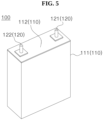
- FIG. 5 illustrates a battery cell based on an embodiment of the disclosed technology.
- a battery cell 100 may include a cell body 110.
- the cell body 110 may include a cell case 111.
- the cell case 111 may form at least a portion of an external appearance of the cell body 110.
- the cell case 111 may form a space inside.
- the space formed in the cell case 111 may be open toward or from one side.
- the cell case 111 may form an open space facing upward.
- the space formed in the cell case 111 may be open at a top of the cell case 111.
- the cell body 110 may include an electrode assembly (not shown).
- the electrode assembly may include an anode, a cathode, and a separator.
- the cell case 111 may accommodate the electrode assembly.
- the cell case 111 may accommodate an electrolyte.
- the cell body 110 may include a cap assembly 112.
- the cap assembly 112 may be coupled or connected or fastened to the cell case 111.
- the cap assembly 112 may form another portion of the external appearance of the cell body 110.
- the cap assembly 112 may form the shape of a board or plate.
- the cap assembly 112 may form one surface of the cell body 110.
- the cap assembly 112 may form an upper surface of the cell body 110.
- the cap assembly 112 may block the open space formed in the cell case 111.
- the battery cell 100 may include an electrode lead 120.
- the electrode lead 120 may be connected to the electrode assembly (not shown).
- the electrode lead 120 may extend from the electrode assembly (not shown).
- the electrode lead 120 may protrude from the cell body 110.
- the electrode lead 120 may protrude from the cap assembly 112.
- the electrode lead 120 may protrude outward from an outer surface of the cap assembly 112.
- the electrode lead 120 may form a pillar shape.
- the electrode lead 120 may have a cylindrical shape.
- a plurality of electrode leads 120 may be provided.
- the electrode lead 120 may include a first electrode lead 121 and a second electrode lead 122.
- the first electrode lead 121 and the second electrode lead 122 may be spaced apart from each other.
- the first electrode lead 121 and the second electrode lead 122 may be positioned on or coupled to the cap assembly 112.
- the space formed in the cell case 111 may be open on both sides.
- the space formed in the cell case 111 may be open upward and downward.
- two cap assemblies 112 may be provided.
- the upper cap assembly 112 may be coupled to the top of the cell case 111
- the lower cap assembly 112 may be coupled to a bottom of the cell case 111.
- the first electrode lead 121 may be coupled to or positioned on the upper cap assembly 112
- the second electrode lead 122 may be coupled to or positioned on the lower cap assembly 112.
- FIG. 5 illustrates that the battery cell 100 is positioned so that the cap assembly 112 faces upward, but a posture of the battery cell 100 loaded on the rack assembly 300 (see FIG. 4 ) is not limited to that illustrated in FIG. 5 .
- the cap assembly 112 may face toward a horizontal direction, and the cell case 111 may face the rack deck 312 (see FIG. 1 ).
- FIG. 6 illustrates a battery pack based on an embodiment of the disclosed technology. Only a portion of a battery pack 10 may be illustrated in FIG. 6 for convenience of explanation.
- the plurality of battery cells 100 may be stacked in one direction.
- the plurality of battery cells 100 may be arranged in the horizontal direction between the two rack decks 312 that are adjacent to each other in the up-down direction.
- the plurality of battery cells 100 may be arranged back and forth between the two rack decks 312 that are adjacent to each other in the up-down direction.
- the battery cells 100 may be sandwiched between the two rack decks 312 adjacent to each other in the up-down direction. For example, when the battery cells 100 move in a direction facing toward the surface positioned opposite the cap assembly 112 among the surfaces of the cell case 111, the battery cells 100 may be sandwiched between the two rack decks 312 adjacent to each other in the up-down direction.
- the battery cells 100 When the battery cells 100 move in the direction toward which the cap assembly 112 faces, the battery cells 100 sandwiched between the two rack decks 312 adjacent to each other in the up-down direction may be separated from the rack assembly 300. In this way, the battery cells 100 can be easily coupled to or separated from the rack assembly 300.
- FIG. 7 partially illustrates the battery cell and the tray illustrated in FIG. 6 .
- FIG. 8 illustrates the battery cell and the tray illustrated in FIG. 7 when viewed from another angle.
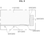
- FIG. 9 illustrates an area 'A' illustrated in FIG. 8 .
- the tray 320 may include a lower tray 320x and an upper tray 320y.
- the lower tray 320x and the upper tray 320y may be arranged symmetrically.
- the plurality of battery cells 100 may be positioned between the two trays 320.
- the plurality of battery cells 100 may be arranged in one direction.
- the plurality of battery cells 100 may be arranged between the lower tray 320x and the upper tray 320y in the front-rear direction.
- the plurality of battery cells 100 may include a front battery cell 100c and a rear battery cell 100d.
- the front battery cell 100c may be positioned at the most front among the plurality of battery cells 100.
- the rear battery cell 100d may be positioned at the most rear among the plurality of battery cells 100.
- the lower tray 320x may be positioned below the plurality of battery cells 100.
- the lower tray 320x may support the plurality of battery cells 100.
- the lower tray 320x may face or contact the lower surfaces of the plurality of battery cells 100.
- the lower tray 320x may face or contact one surfaces of the cell cases 111 of the plurality of battery cells 100.
- the upper tray 320y may be positioned above the plurality of battery cells 100.
- the upper tray 320y may face or contact the upper surfaces of the plurality of battery cells 100.
- the upper tray 320y may face or contact other surfaces of the cell cases 111 of the plurality of battery cells 100.
- the cap assemblies 112 of the plurality of battery cells 100 may be arranged back and forth.
- the cap assemblies 112 of the plurality of battery cells 100 may face or be directed toward one direction.
- the cap assemblies 112 of the plurality of battery cells 100 may face or be directed toward the horizontal direction.
- the cap assembly 112 of each of the plurality of battery cells 100 may extend or form an elongated shape in one direction.
- the cap assembly 112 of each of the plurality of battery cells 100 may extend or form an elongated shape in the up-down direction.
- the cap assembly 112 of each of the plurality of battery cells 100 may extend upward from the lower tray 320x and lead to the upper tray 320y.
- the first electrode lead 121 and the second electrode lead 122 of each of the plurality of battery cells 100 may be arranged up and down.
- the first electrode lead 121 may be positioned above or below the second electrode lead 122.
- the first electrode lead 121 of the preceding battery cell 100 may be positioned in front of the second electrode lead 122 of the subsequent battery cell 100.
- the second electrode lead 122 of the preceding battery cell 100 may be positioned in front of the first electrode lead 121 of the subsequent battery cell 100.
- the tray partition 323 may be positioned between the two adjacent battery cells 100 of the plurality of battery cells 100.
- Each of the plurality of tray seats 327 may be coupled to or in contact with each corresponding battery cell 100 of the plurality of battery cells 100.
- Each of the plurality of tray saddles 326 may be coupled to or in contact with each corresponding battery cell 100 of the plurality of battery cells 100.
- Each of the plurality of tray contactors 325 may be coupled to or in contact with each corresponding battery cell 100 of the plurality of battery cells 100.
- Each of the plurality of tray stoppers 328 may be coupled to or in contact with each corresponding battery cell 100 of the plurality of battery cells 100.
- the tray contactor 325 may support the battery cell 100.
- the tray contactor 325 may support the battery cell 100 on the opposite side of the cap assembly 112 or on the opposite side of the electrode lead 120.
- the tray contactor 325 may be convex toward the battery cell 100.
- one surface of the tray contactor 325 may be inclined with respect to the battery cell 100.
- an area of the surface where the tray contactor 325 and the battery cell 100 contact each other may be relatively small.
- the tray seat 327 and the tray saddle 326 may support the battery cell 100.
- the tray seats 327 and the tray saddles 326 of the lower tray 320x may support the battery cells 100 below the battery cells 100.
- the tray seats 327 and the tray saddles 326 of the upper tray 320y may support the battery cells 100 above the battery cells 100.
- a gap may be formed between the tray body 321 and the battery cell 100.
- the tray seat 327, the tray body 321, and the tray saddle 326 may be concave toward the battery cell 100. Even if the battery cell 100 swells, at least a portion of an increased volume of the battery cell 100 may be accommodated between the tray seat 327 and the tray saddle 326.
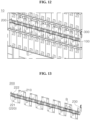
- FIG. 10 illustrates a portion of a cross section of the battery pack illustrated in FIG. 6 .
- FIG. 11 illustrates in detail the rack deck illustrated in FIG. 10 . From FIGS. 10 and 11 , a cross section of the rack deck 312 and the battery cell 100 cut perpendicular to the longitudinal direction of the rack deck 312 may be observed.
- the longitudinal direction of the rack deck 312 may be the front-rear direction.
- the longitudinal direction of the rack deck 312 may be a direction in which the plurality of battery cells 100 are stacked.
- the rack deck 312 may be coupled or fastened to the rack scaffold 311 (see FIG. 1 ).
- the rack scaffold 311 (see FIG. 1 ) may support the rack deck 312.
- a front end and a rear end of the rack deck 312 may be coupled or fastened to the rack scaffold 311 (see FIG. 1 ).
- the rack deck 312 may include a rack deck core 3121.
- the rack deck core 3121 may form the center of the rack deck 312.
- the rack deck core 3121 may form an upward convex shape.
- the rack deck core 3121 may be elongated or extended in the longitudinal direction of the rack deck 312.
- the rack deck 312 may include a rack deck concave portion 3122.
- the rack deck concave portion 3122 may extend from the rack deck core 3121.
- the rack deck concave portion 3122 may extend from the rack deck core 3121 in a width direction of the rack deck 312.
- the rack deck concave portion 3122 may extend in both directions from the rack deck core 3121.
- a first width direction and a second width direction may be parallel to the width direction of the rack deck 312.
- the first width direction and the second width direction may be opposite directions.
- the rack deck concave portion 3122 may include a first rack deck concave portion 3122t extending from the rack deck core 3121 in the first width direction.
- the rack deck concave portion 3122 may include a second rack deck concave portion 3122u extending from the rack deck core 3121 in the second width direction.
- the first width direction may be a direction from the rack deck core 3121 toward the first rack deck concave portion 3122t.
- the second width direction may be a direction from the rack deck core 3121 toward the second rack deck concave portion 3122u.
- the rack deck concave portion 3122 may include or indicate at least one of the first rack deck concave portion 3122t or the second rack deck concave portion 3122u.
- the rack deck concave portion 3122 may be convex downward.
- the rack deck concave portion 3122 may be concave upward.
- the rack deck 312 may include a rack deck convex portion 3123.
- the rack deck convex portion 3123 may extend from the rack deck concave portion 3122.
- the rack deck convex portion 3123 may extend from the rack deck concave portion 3122 in the width direction of the rack deck 312.
- the rack deck convex portion 3123 may include a first rack deck convex portion 3123t extending from the first rack deck concave portion 3122t in the first width direction.
- the rack deck convex portion 3123 may include a second rack deck convex portion 3123u extending from the second rack deck concave portion 3122u in the second width direction.
- the rack deck convex portion 3123 may include or indicate at least one of the first rack deck convex portion 3123t or the second rack deck convex portion 3123u.
- the rack deck convex portion 3123 may be convex upward.
- the rack deck convex portion 3123 may be concave downward.
- the rack deck 312 may include a rack deck end 3124.
- the rack deck end 3124 may be formed to extend downward from the rack deck convex portion 3123.
- the rack deck end 3124 may be formed to extend downward from an end of the rack deck convex portion 3123 and bend and extend toward the rack deck core 3121.
- the rack deck end 3124 may include a first rack deck end 3124t extending downward from the first rack deck convex portion 3123t.
- the rack deck end 3124 may include a second rack deck end 3124u extending downward from the second rack deck convex portion 3123u.
- the rack deck end 3124 may include or indicate at least one of the first rack deck end 3124t or the second rack deck end 3124u.
- the rack deck end 3124 may face downward.
- the rack deck end 3124 may be concave toward the rack deck core 3121.
- the rack deck concave portion 3122 and the rack deck convex portion 3123 may be concave or convex toward different directions.
- the rack deck 312 may have elasticity.
- the rack deck 312 may be formed of a material containing metal. Because the rack deck 312 has the elasticity, the battery cell 100 can be easily loaded on the rack assembly 300 (see FIG. 1 ) or easily separated from the rack assembly 300 (see FIG. 1 ).
- the battery cell 100 may be disposed between the two rack decks 312 adjacent to each other in the up-down direction.
- a lower rack deck 312x may be positioned below the battery cell 100.
- an upper rack deck 312y may be positioned above the battery cell 100.
- the tray 320 may be coupled to the rack deck 312.
- the lower tray 320x may be disposed above the lower rack deck 312x and coupled to the lower rack deck 312x.
- the lower tray 320x may be coupled to the rack deck convex portion 3123 of the lower rack deck 312x.
- the rack deck convex portion 3123 of the lower rack deck 312x below the lower tray 320x may support the lower tray 320x.
- the upper tray 320y may be disposed below the upper rack deck 312y and coupled to the upper rack deck 312y.
- the upper tray 320y may be coupled to the rack deck concave portion 3122 of the upper rack deck 312y.
- the rack deck concave portion 3122 of the upper rack deck 312y above the upper tray 320y may support the upper tray 320y.
- the plurality of trays 320 may be disposed on both sides of the rack deck 312 based on the width direction of the rack deck 312.
- a first tray 320t may be coupled to the first rack deck concave portion 3122t or the first rack deck convex portion 3123t.
- a first lower tray 320tx may be coupled to the first rack deck convex portion 3123t of the lower rack deck 312x.
- a first upper tray 320ty may be coupled to the first rack deck concave portion 3122t of the upper rack deck 312y.
- the first tray 320t may include or indicate at least one of the first lower tray 320tx or the first upper tray 320ty.
- a second tray 320u may be coupled to the second rack deck concave portion 3122u or the second rack deck convex portion 3123u.
- a second lower tray 320ux may be coupled to the second rack deck convex portion 3123u of the lower rack deck 312x.
- a second upper tray 320uy may be coupled to the second rack deck concave portion 3122u of the upper rack deck 312y.
- the second tray 320u may include or indicate at least one of the second lower tray 320ux or the second upper tray 320uy.
- the lower tray 320x may include or indicate at least one of the first lower tray 320tx or the second lower tray 320ux.
- the upper tray 320y may include or indicate at least one of the first upper tray 320ty or the second upper tray 320uy.
- the battery cell 100 may include a first battery cell 100t and a second battery cell 100u.
- the battery cell 100 may include or indicate at least one of the first battery cell 100t or the second battery cell 100u.
- the first battery cell 100t may be positioned between the first lower tray 320tx and the first upper tray 320ty.
- the second battery cell 100u may be positioned between the second lower tray 320ux and the second upper tray 320uy.
- the cap assembly 112 (see FIG. 5 ) of the first battery cell 100t may be directed toward or face the first width direction.
- the cap assembly 112 (see FIG. 5 ) of the second battery cell 100u may be directed toward or face the second width direction.
- FIG. 12 illustrates that a bus bar assembly is coupled to the battery cells loaded on the rack assembly.
- the plurality of battery cells 100 may be stacked in the front-rear direction.
- the plurality of battery cells 100 may be positioned between the two adjacent rack decks 312 (see FIG. 1 ) disposed up and down.
- the plurality of battery cells 100 stacked in the front-rear direction may be connected by a bus bar assembly 200.
- the bus bar assembly 200 may be extended or elongated in the front-rear direction.
- the bus bar assembly 200 may face the cap assemblies 112 (see FIG. 5 ) of the plurality of battery cells 100.
- the bus bar assembly 200 may be connected or coupled to the electrode leads 120 (see FIG. 5 ) of the plurality of battery cells 100.
- FIG. 13 is a perspective view of the bus bar assembly based on an embodiment of the disclosed technology.
- the bus bar assembly 200 may include bus bars 210.
- the bus bar 210 may be formed of a conductive material.
- the bus bar 210 may be formed of a material containing metal.
- the bus bar 210 may connect two adjacent battery cells 100 (see FIG. 12 ).
- the bus bar 210 may be coupled to two battery cells 100 (see FIG. 12 ) adjacent to each other in the front-rear direction.
- a front end of the bus bar 210 may be coupled to the first electrode lead 121 (see FIG. 5 ) of the preceding battery cell 100 (see FIG. 12 ), and a rear end of the bus bar 210 may be coupled to the second electrode lead 122 (see FIG. 5 ) of the subsequent battery cell 100 (see FIG. 12 ).
- a polarity of the first electrode lead 121 (see FIG. 5 ) of the preceding battery cell 100 (see FIG. 12 ) may be opposite to a polarity of the second electrode lead 122 (see FIG. 5 ) of the subsequent battery cell 100 (see FIG. 12 ).
- the bus bar assembly 200 may include a support frame 220.
- the support frame 220 may include a frame body 221.
- the frame body 221 may be extended or elongated in one direction.
- the frame body 221 may be extended or elongated in the front-rear direction.
- the frame body 221 may be formed of an insulating material.
- the frame body 221 may be formed of a material containing a polymer material or plastic.
- the frame body 221 may face the cap assemblies 112 (see FIG. 5 ) of the plurality of battery cells 100.
- an inner surface of the frame body 221 may face the cap assemblies 112 (see FIG. 5 ) of the plurality of battery cells 100.
- the frame body 221 may be positioned between the first electrode lead 121 (see FIG. 5 ) and the second electrode lead 122 (see FIG. 5 ) of each of the plurality of battery cells 100.
- the frame body 221 may cross between the first electrode lead 121 (see FIG. 5 ) and the second electrode lead 122 (see FIG. 5 ) of each of the plurality of battery cells 100.
- the support frame 220 may be coupled to the plurality of bus bars 210.
- a portion of the plurality of bus bars 210 may be coupled to an upper end of the support frame 220.
- another portion of the plurality of bus bars 210 may be coupled to a lower end of the support frame 220.
- the support frame 220 may include a wire holder 222.
- the wire holder 222 may be positioned or formed on or coupled to the frame body 221.
- the wire holder 222 may be positioned or formed on or coupled to an outer surface of the frame body 221.
- the wire holder 222 may be coupled to a wire unit 230.
- a wire of the wire unit 230 may be mounted on the wire holder 222.
- the wire unit 230 may be coupled to the bus bar 210 to obtain information on the battery cell 100 (see FIG. 12 ).
- a plurality of wire holders 222 may be provided.
- the plurality of wire holders 222 may be arranged to be spaced apart from each other in the front-rear direction.
- the wire of the wire unit 230 may be disposed along the plurality of wire holders 222.
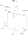
- FIG. 14 is a perspective view of the bus bar based on an embodiment of the disclosed technology.
- FIG. 15 is a plan view of the bus bar illustrated in FIG. 14 .
- the bus bar 210 may include a bus bar body 211.
- the bus bar body 211 may form a center portion of the bus bar 210.
- the bus bar body 211 may face a boundary of two battery cells 100 (see FIG. 12 ) adjacent to each other in the front-rear direction.
- an inner surface of the bus bar body 211 may face the boundary of the two adjacent battery cells 100 (see FIG. 12 ).
- the inner surface of the bus bar body 211 may be spaced apart from the battery cell 100 (see FIG. 12 ). In other words, a gap may be formed between the bus bar body 211 and the battery cell 100 (see FIG. 12 ).
- the bus bar body 211 may be coupled to the support frame 220 (see FIG. 13 ).
- the bus bar 210 may include a frame coupling hole 212.
- the frame coupling hole 212 may be an opening formed in the bus bar body 211.
- the frame coupling hole 212 may extend from the inner surface of the bus bar body 211 and lead to an outer surface of the bus bar body 211.
- a protrusion formed on the support frame 220 may be inserted into the frame coupling hole 212.
- the frame coupling hole 212 may be elongated in the up-down direction.
- the protrusion formed on the support frame 220 may move in the up-down direction in the frame coupling hole 212.
- the support frame 220 (see FIG. 13 ) and the bus bar 210 may be disposed up and down.
- the support frame 220 (see FIG. 13 ) and the bus bar 210 can be easily coupled to each other by the frame coupling hole 212 elongated in the up-down direction.
- the bus bar 210 may include a bus bar wing 215.
- the bus bar wing 215 may extend from the bus bar body 211.
- the bus bar 210 may be concave toward the battery cell 100 (see FIG. 5 ).
- the inner surface of the bus bar 210 may be concave.
- the inner surface of the bus bar 210 may face the battery cell 100 (see FIG. 5 ).
- a plurality of bus bar wings 215 may be provided.
- the bus bar 210 may include a front bus bar wing 216 and a rear bus bar wing 217.
- the bus bar wing 215 may include or indicate at least one of the front bus bar wing 216 or the rear bus bar wing 217.
- the bus bar wing 215 may form a step with the bus bar body 211.
- the bus bar wing 215 may be bent and extended from a front end or a rear end of the bus bar body 211 toward the battery cell 100 (see FIG. 12 ) and may extend forward or rearward.
- the front bus bar wing 216 may be bent and extended from the front end of the bus bar body 211 toward the battery cell 100 (see FIG. 12 ) and may extend forward.
- the bus bar 210 may include a bus bar link 219 that is bent and extended from the front end of the bus bar body 211 toward the battery cell 100 (see FIG. 12 ).
- the front bus bar wing 216 may extend forward from an end of the bus bar link 219.
- the rear bus bar wing 217 may be bent and extended from the rear end of the bus bar body 211 toward the battery cell 100 (see FIG. 12 ) and may extend rearward.
- the bus bar 210 may include a bus bar link 219 that is bent and extended from the rear end of the bus bar body 211 toward the battery cell 100 (see FIG. 12 ).
- the rear bus bar wing 217 may extend rearward from an end of the bus bar link 219.
- the bus bar wing 215 may face the cap assembly 112 (see FIG. 5 ) of the battery cell 100 (see FIG. 12 ).
- an inner surface of the bus bar wing 215 may face the cap assembly 112 (see FIG. 5 ) of the battery cell 100 (see FIG. 12 ).
- the bus bar wing 215 may be coupled to the electrode lead 120 (see FIG. 5 ) of the battery cell 100 (see FIG. 12 ).
- the bus bar 210 may include a cell coupling hole 218.
- the cell coupling hole 218 may be an opening or a hole formed in the bus bar wing 215.
- the electrode lead 120 (see FIG. 5 ) of the preceding battery cell 100 may be coupled to the cell coupling hole 218 formed in the front bus bar wing 216
- the electrode lead 120 (see FIG. 5 ) of the subsequent battery cell 100 may be coupled to the cell coupling hole 218 formed in the rear bus bar wing 217.
- the cell coupling hole 218 may be elongated in the front-rear direction.
- the electrode lead 120 (see FIG. 5 ) of the battery cell 100 (see FIG. 12 ) may be inserted into the cell coupling hole 218.
- the cell coupling hole 218 may extend from the inner surface of the bus bar wing 215 and lead to an outer surface of the bus bar wing 215.
- a thread may be formed on an outer surface of the electrode lead 120 (see FIG. 5 ).
- a nut (not shown) may be screwed to the electrode lead 120 (see FIG. 5 ).
- the electrode lead 120 (see FIG. 5 ) of the battery cell 100 may move in the front-rear direction in the cell coupling hole 218.
- the coupling between the electrode lead 120 (see FIG. 5 ) and the bus bar 210 can be easily maintained.
- the bus bar 210 may form a perimeter based on the inner surface or the outer surface of the bus bar 210.
- an upper bus bar edge 210a may form a portion of the perimeter of the bus bar 210 and form an upper end of the bus bar 210.
- a lower bus bar edge 210b may form a portion of the perimeter of the bus bar 210 and form a lower end of the bus bar 210.
- a front bus bar edge 210c may form a portion of the perimeter of the bus bar 210 and form a front end of the bus bar 210.
- the front bus bar edge 210c may be formed on the front bus bar wing 216.
- a rear bus bar edge 210d may form a portion of the perimeter of the bus bar 210 and form a rear end of the bus bar 210.
- the rear bus bar edge 210d may be formed on the rear bus bar wing 217.
- FIG. 16 is a plan view of a support frame based on an embodiment of the disclosed technology.
- an outer surface of the support frame 220 may be observed.
- a direction toward which the outer surface of the support frame 220 faces may be opposite to a direction toward which an inner surface of the support frame 220 faces.
- the inner surface of the support frame 220 may be directed toward or face the battery cell 100 (see FIG. 12 ).
- the support frame 220 may include the frame body 221.
- the frame body 221 may be elongated or extended in the direction in which the plurality of battery cells 100 (see FIG. 12 ) are stacked.
- the frame body 221 may be elongated or extended in the front-rear direction.
- the frame body 221 may form a perimeter based on the inner surface or the outer surface of the frame body 221.
- an upper frame body edge 221a may form a portion of the perimeter of the frame body 221 and form an upper end of the frame body 221.
- a lower frame body edge 221b may form a portion of the perimeter of the frame body 221 and form a lower end of the frame body 221.
- a front frame body edge 221c may form a portion of the perimeter of the frame body 221 and form a front end of the frame body 221.
- a rear frame body edge 221d may form a portion of the perimeter of the frame body 221 and form a rear end of the frame body 221.
- the support frame 220 may include a frame wing 225.
- the frame wing 225 may extend from the frame body 221 or may be coupled to the frame body 221.
- the frame wing 225 may be formed integrally with the frame body 221.
- the frame wing 225 may extend upward from the upper frame body edge 221a of the frame body 221.
- the frame wing 225 may extend downward from the lower frame body edge 221b of the frame body 221.
- the support frame 220 may include a frame rib 226.
- the frame rib 226 may extend from or be coupled to the frame wing 225.
- the frame rib 226 may protrude from an outer surface of the frame wing 225.
- the frame rib 226 may be formed integrally with the frame wing 225.
- the frame rib 226 may be coupled to the bus bar 210 (see FIGS. 14 and 15 ).
- the frame rib 226 may be inserted into and coupled to the frame coupling hole 212 (see FIGS. 14 and 15 ) of the bus bar 210 (see FIGS. 14 and 15 ).
- FIG. 17 illustrates a portion 'B' of FIG. 13 .
- FIG. 18 is a cross-sectional view of the bus bar assembly taken along C1-C2 of FIG. 17 .
- the frame wing 225 may be positioned between the front bus bar wing 216 and the rear bus bar wing 217.
- the frame wing 225 may be positioned between the bus bar body 211 and the battery cell 100 (see FIG. 12 ).
- the outer surface of the frame wing 225 may face the bus bar body 211.
- a washer 242 may be disposed between the frame wing 225 and the bus bar body 211.
- an inner surface of the frame wing 225 may face the battery cell 100 (see FIG. 12 ).
- the frame rib 226 may protrude from the outer surface of the frame wing 225.
- the frame rib 226 may be a press-fit bolt coupled to the frame wing 225.
- the frame rib 226 may pass through the bus bar body 211.
- a thread may be formed on an outer surface of the frame rib 226.
- a nut (not shown) may be coupled to the frame rib 226.
- the wire unit 230 (see FIG. 13 ) may be coupled between the bus bar body 211 and the nut (not shown). Hence, the wire unit 230 (see FIG. 13 ) may be electrically connected to the bus bar body 211.
- the bus bar assembly 200 may be coupled to the plurality of battery cells 100 stacked in the front-rear direction. A process of replacing one of the plurality of battery cells 100 stacked in the front-rear direction is described.
- the bus bar assembly 200 may be separated from the plurality of battery cells 100.
- the plurality of bus bars 210 may be separated from the plurality of battery cells 100.
- a nut (not shown) coupled to the electrode lead 120 may be separated from the electrode lead 120 (see FIG. 5 ).
- the battery cell 100 to be replaced among the plurality of battery cells 100 may be taken out of the rack assembly 300.
- a new battery cell 100 may be loaded into the rack assembly 300.
- the bus bar assembly 200 may be coupled to the plurality of battery cells 100.
- the electrode leads 120 (see FIG. 5 ) of the plurality of battery cells 100 may be inserted into the cell coupling holes 218.
- the nut (not shown) may be coupled to the electrode lead 120 (see FIG. 5 ).
- FIG. 19 is a perspective view illustrating an overall appearance of a battery pack based on an embodiment of the disclosed technology.
- a plurality of rack frames 310 may be provided.
- the plurality of rack frames 310 may be arranged in one direction.
- the plurality of rack frames 310 may be sequentially arranged in a transverse direction of the rack decks 312 (see FIG. 1 ) or a transverse direction of the trays 320 (see FIG. 2 ).
- the plurality of rack frames 310 may move in the transverse direction of the rack decks 312 (see FIG. 1 ) or the transverse direction of the trays 320 (see FIG. 2 ).
- the rack frame 310 may include a rack guide 313.
- the rack guide 313 may be formed on or coupled to the rack scaffold 311.
- the rack guide 313 may be extended or elongated in the transverse direction of the rack deck 312 (see FIG. 1 ) or the transverse direction of the tray 320 (see FIG. 2 ).
- the rack guide 313 may be a groove formed at a lower end of the rack scaffold 311.
- the rack guide 313 may be a rail coupled to the lower end of the rack scaffold 311 or a protrusion coupled to the lower end of the rack scaffold 311.
- FIG. 20 illustrates an energy storage house based an embodiment of the disclosed technology.
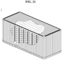
- FIG. 21 illustrates an energy storage system based an embodiment of the disclosed technology.
- an energy storage system 1 based an embodiment of the disclosed technology may include an energy storage house 20 and the plurality of battery packs 10 (see FIG. 19 ).
- the energy storage house 20 may accommodate the battery pack 10 (see FIG. 19 ).
- the energy storage house 20 may accommodate the plurality of battery packs 10 (see FIG. 19 ).
- the energy storage house 20 may include a house bottom 21.
- the house bottom 21 may form the bottom of the energy storage house 20.
- the house bottom 21 may be positioned below the battery pack 10 (see FIG. 19 ).
- the energy storage house 20 may include a house guide 22.
- the house guide 22 may be formed on or coupled to the house bottom 21.
- the house guide 22 may be extended or elongated in a longitudinal direction.
- the longitudinal direction of the house guide 22 may be parallel to a direction in which the plurality of battery packs 10 (see FIG. 19 ) are arranged.
- the longitudinal direction of the house guide 22 may be parallel to the transverse direction of the rack deck 312 (see FIG. 1 ) or the transverse direction of the tray 320 (see FIG. 2 ).
- the house guide 22 may be coupled to the rack guide 313 (see FIG. 19 ).
- the house guide 22 may guide the movement of the battery pack 10 (see FIG. 19 ).
- the battery pack 10 (see FIG. 19 ) may move along the house guide 22.
- the rack guide 313 and the house guide 22 may be engaged with each other.
- the house guide 22 may include a rail
- the rack guide 313 (see FIG. 19 ) may include a groove formed on a lower surface of the rack scaffold 311 (see FIG. 19 ).
- the house guide 22 may include a groove formed on the house bottom 21, and the rack guide 313 (see FIG. 19 ) may include a rail or a protrusion.
Landscapes
- Chemical & Material Sciences (AREA)
- Chemical Kinetics & Catalysis (AREA)
- Electrochemistry (AREA)
- General Chemical & Material Sciences (AREA)
- Engineering & Computer Science (AREA)
- Aviation & Aerospace Engineering (AREA)
- Battery Mounting, Suspending (AREA)
Abstract
A rack assembly (300) is disclosed. The rack assembly (300) comprises a rack frame (310) including a rack scaffold (311) and a rack deck (312) coupled to the rack scaffold (311), and a tray (320) coupled to the rack deck (312). The rack deck (312) is elongated in a front-rear direction. The tray (320) includes a tray body (321) facing the rack deck (312) and positioned above the rack deck (312), and a tray wall (322) extending upward from an edge of the tray body (321). The edge of the tray body (321) extends rearward from a front end of the tray body (321) and leads to a rear end of the tray body (321).
Description
- The technology and implementations disclosed in this patent document generally relate to a rack assembly and a battery pack including the same. In particular, the disclosed technology relates to a rack assembly, in which battery cells are easily replaced, and a battery pack including the same.
- In an existing battery pack or energy storage system (ESS), a plurality of battery cells was stacked, coupled to a bus bar, and loaded on a battery rack. Due to this structure, the process of installing or replacing the plurality of battery cells in the battery rack in the existing battery pack or energy storage system may be very complicated, and the cost may be relatively high.
- (Patent Document 1)
US 11502363 B2 - The disclosed technology can be implemented in some embodiments to address the above-described and other problems.
- The disclosed technology can also be implemented in some embodiments to provide a rack assembly, that is easy to load a plurality of battery cells, and a battery pack including the same.
- The disclosed technology can also be implemented in some embodiments to provide a rack assembly, that is easy to replace a plurality of battery cells, and a battery pack including the same.
- To solve the above-described and other technical problems, in one aspect of the present disclosure, a rack assembly may comprise a rack frame including a rack scaffold and a rack deck, the rack deck coupled to the rack scaffold; and a tray coupled to the rack deck, wherein the rack deck is elongated in a front-rear direction, wherein the tray includes a tray body facing the rack deck, the tray body positioned above the rack deck; and a tray wall extending upward from an edge of the tray body, wherein the edge of the tray body extends rearward from a front end of the tray body and leads to a rear end of the tray body.
- In another aspect of the present disclosure, a battery pack may comprise a rack assembly including a rack frame and a tray coupled to the rack frame; a plurality of battery cells loaded on the tray and stacked in a front-rear direction; and a bus bar assembly coupled to the plurality of battery cells, wherein the rack frame includes a rack scaffold and a rack deck coupled to the rack scaffold, wherein the rack deck is elongated in the front-rear direction, wherein the tray includes a tray body facing the rack deck, the tray body positioned above the rack deck; a tray coupler extending from the tray body, the tray coupler coupled to the rack deck; and a tray wall extending upward from an edge of the tray body, wherein the edge of the tray body extends rearward from a front end of the tray body and leads to a rear end of the tray body.
- According to at least one aspect of the present disclosure, a rack assembly, that is easy to load a plurality of battery cells, and a battery pack including the same can be provided.
- According to at least one aspect of the present disclosure, a rack assembly, that is easy to replace a plurality of battery cells, and a battery pack including the same can be provided.
- The accompanying drawings illustrate examples of embodiments of various technical features disclosed in the disclosure.
-
FIG. 1 illustrates a rack frame of a rack assembly based on an embodiment of the disclosed technology. -
FIG. 2 illustrates a tray based on an embodiment of the disclosed technology. -
FIG. 3 illustrates a tray illustrated inFIG. 2 when viewed from another angle. -
FIG. 4 illustrates a rack assembly including a tray and a rack frame. -
FIG. 5 illustrates a battery cell based on an embodiment of the disclosed technology. -
FIG. 6 illustrates a battery pack based on an embodiment of the disclosed technology. -
FIG. 7 partially illustrates a battery cell and a tray illustrated inFIG. 6 . -
FIG. 8 illustrates a battery cell and a tray illustrated inFIG. 7 when viewed from another angle. -
FIG. 9 illustrates an area 'A' illustrated inFIG. 8 . -
FIG. 10 illustrates a portion of a cross section of a battery pack illustrated inFIG. 6 . -
FIG. 11 illustrates in detail a rack deck illustrated inFIG. 10 . -
FIG. 12 illustrates that a bus bar assembly is coupled to battery cells loaded on a rack assembly. -
FIG. 13 is a perspective view of a bus bar assembly based on an embodiment of the disclosed technology. -
FIG. 14 is a perspective view of a bus bar based on an embodiment of the disclosed technology. -
FIG. 15 is a plan view of a bus bar illustrated inFIG. 14 . -
FIG. 16 is a plan view of a support frame based on an embodiment of the disclosed technology. -
FIG. 17 illustrates a portion 'B' ofFIG. 13 . -
FIG. 18 is a cross-sectional view of a bus bar assembly taken along C1-C2 ofFIG. 17 . -
FIG. 19 is a perspective view illustrating an overall appearance of a battery pack based on an embodiment of the disclosed technology. -
FIG. 20 illustrates an energy storage house based an embodiment of the disclosed technology. -
FIG. 21 illustrates an energy storage system based an embodiment of the disclosed technology. - Reference will now be made in detail to embodiments of the disclosed technology, examples of which are illustrated in the accompanying drawings. However, the following description is merely an example and does not intended to limit the disclosed technology to a specific implementation.
-
FIG. 1 illustrates a rack frame of a rack assembly based on an embodiment of the disclosed technology. - Referring to
FIG. 1 , arack assembly 300 may include arack frame 310. Therack frame 310 may include arack scaffold 311. Therack scaffold 311 may form a skeleton of therack frame 310. - For example, the
rack scaffold 311 may form a bottom of therack frame 310. For example, therack scaffold 311 may form a top of therack frame 310. For example, therack scaffold 311 may form a pillar of therack frame 310. - The
rack frame 310 may include arack deck 312. Therack deck 312 may form the shape of a board or plate. For example, therack deck 312 may form an upper surface and a lower surface. - The
rack deck 312 may be coupled or fastened to therack scaffold 311. Therack deck 312 may serve as a shelf. For example, a plurality of battery cells may be loaded on therack deck 312. - The
rack deck 312 may extend or form an elongated shape in one direction. For example, therack deck 312 may extend or form an elongated shape in a front-rear direction. A longitudinal direction of therack deck 312 may be the front-rear direction. - A plurality of
rack decks 312 may be provided. For example, therack frame 310 may include a plurality ofrack decks 312. At least a portion of the plurality ofrack decks 312 may be arranged to be spaced apart up and down. - For example, in two
rack decks 312 that are adjacent to each other in the up-down direction, a lower surface of therack deck 312 disposed above may face an upper surface of therack deck 312 disposed below. - The
rack frame 310 may have rigidity. For example, therack frame 310 may be formed of a material containing metal. For example, therack frame 310 may be electrically conductive. -
FIG. 2 illustrates a tray based on an embodiment of the disclosed technology.FIG. 3 illustrates a tray illustrated inFIG. 2 when viewed from another angle. - Referring to
FIGS. 2 and 3 , atray 320 may be formed of a material containing an electrical insulating material. For example, thetray 320 may be formed of a material containing a polymer compound or plastic. - The
tray 320 may include atray body 321. Thetray body 321 may form the shape of a board or plate. For example, thetray body 321 may form two surfaces. - For example, the
tray body 321 may form an upper surface and a lower surface. A thickness of thetray body 321 may be a distance between the upper surface and the lower surface of thetray body 321. - The
tray body 321 may extend or form an elongated shape in one direction. For example, the direction in which thetray body 321 is extended or elongated may be a longitudinal direction of thetray body 321. For example, the longitudinal direction of thetray body 321 may be the front-rear direction. - An edge and another edge of the
tray body 321 may be positioned opposite to each other. The edge and the another edge of thetray body 321 may extend in the longitudinal direction of thetray body 321. A width direction of thetray body 321 may be parallel to a direction from the edge of thetray body 321 to the another edge of thetray body 321. - The
tray 320 may include atray wall 322. Thetray wall 322 may extend from the edge of thetray body 321. For example, thetray wall 322 may extend rearward from a side of a front end of thetray body 321 and lead to a side of a rear end of thetray body 321. For example, thetray wall 322 may extend upward from the edge of thetray body 321. Thetray wall 322 may form a height relative to thetray body 321. - The
tray 320 may include atray partition 323. Thetray partition 323 may be positioned or disposed on one surface of thetray body 321. For example, thetray partition 323 may protrude from the upper surface of thetray body 321. - The
tray partition 323 may extend or form an elongated shape in the width direction of thetray body 321. For example, an end of thetray partition 323 may be connected or adjacent to thetray wall 322, and another end of thetray partition 323 may be connected or adjacent to the another end of thetray body 321. - A plurality of
tray partitions 323 may be provided. For example, thetray 320 may include a plurality oftray partitions 323. The plurality oftray partitions 323 may be arranged in the longitudinal direction of thetray body 321. For example, the plurality oftray partitions 323 may be arranged in the front-rear direction. - The plurality of
tray partitions 323 may be spaced apart from each other. For example, a distance between twoadjacent tray partitions 323 of the plurality oftray partitions 323 may be based on a size of the battery cell mounted on thetray 320. - The
tray 320 may include atray contactor 325. Thetray contactor 325 may be connected or coupled to or formed on thetray wall 322. Thetray contactor 325 may protrude from thetray wall 322. For example, thetray contactor 325 may protrude from thetray wall 322 toward the another edge of thetray body 321. - The
tray 320 may include atray saddle 326. Thetray saddle 326 may be positioned on or coupled or connected to the upper surface of thetray body 321. For example, thetray saddle 326 may protrude from the upper surface of thetray body 321. Thetray saddle 326 may be adjacent to thetray wall 322. - A plurality of tray saddles 326 may be provided. For example, the
tray 320 may include a plurality of tray saddles 326. The plurality of tray saddles 326 may be arranged in the longitudinal direction of thetray body 321. - For example, the plurality of tray saddles 326 and the plurality of
tray partitions 323 may be arranged in the longitudinal direction of thetray body 321 and may be alternately disposed. For example, onetray partition 323 of the plurality oftray partitions 323 may be disposed between two adjacent tray saddles 326 of the plurality of tray saddles 326. - The
tray 320 may include atray seat 327. Thetray seat 327 may be formed on or coupled to the upper surface of thetray body 321. Thetray seat 327 may protrude from the upper surface of thetray body 321. - The
tray seat 327 may be positioned on or connected or adjacent to the another edge of thetray body 321. For example, thetray seat 327 may be positioned opposite thetray saddle 326. - A plurality of
tray seats 327 may be provided. For example, thetray 320 may include a plurality of tray seats 327. The plurality oftray seats 327 may respectively correspond to the plurality of tray saddles 326. - The
tray seat 327, thetray body 321, and thetray saddle 326 may form a concave upward shape. When the battery cell is mounted on thetray 320, thetray seat 327 and thetray saddle 326 may be in contact with the battery cell, and thetray body 321 may be spaced apart from the battery cell. - Hence, a refrigerant gas can flow through a gap between the battery cell and the
tray body 321, and thus the battery cell can be effectively cooled. In addition, when swelling occurs in the battery cell, the gap between the battery cell and thetray body 321 can accommodate the swollen battery cell. - The
tray 320 may include atray stopper 328. Thetray stopper 328 may be positioned at or adjacent or connected to the another end of thetray body 321. Thetray stopper 328 may be positioned on or coupled to the upper surface of thetray seat 327. Thetray stopper 328 may protrude upward from thetray seat 327. - When the battery cell is mounted on the
tray 320, the battery cell may be disposed between thetray stopper 328 and thetray contactor 325. Thetray stopper 328 and thetray contactor 325 can prevent movement of the battery cell. For example, thetray stopper 328 and thetray contactor 325 can prevent the battery cell from moving in the width direction of thetray body 321. - The
tray 320 may be coupled or fastened to the rack frame 310 (seeFIG. 1 ). For example, thetray 320 may include atray coupler 324. Thetray coupler 324 may be positioned on or coupled or connected to thetray body 321. Thetray coupler 324 may protrude downward from the lower surface of thetray body 321. - The
tray coupler 324 may be coupled or fastened to the rack frame 310 (seeFIG. 1 ). Thetray coupler 324 may form a hook shape. For example, thetray coupler 324 may be coupled or fastened to the rack deck 312 (seeFIG. 1 ). -
FIG. 4 illustrates a rack assembly including a tray and a rack frame. - Referring to
FIGS. 1 to 4 , thetray 320 may be coupled to therack frame 310. For example, thetray 320 may be coupled to therack deck 312. For example, each of the upper surface and the lower surface of therack deck 312 may be coupled to thetray 320. - For example, one
rack deck 312 may be coupled to twotrays 320. For example, the twotrays 320 may be disposed between two rackdecks 312 adjacent to each other in the up-down direction. For example, when one surface of onerack deck 312 of the twoadjacent rack decks 312 faces theother rack deck 312, thetray 320 may be coupled or fastened to the one surface of the onerack deck 312. -
FIG. 5 illustrates a battery cell based on an embodiment of the disclosed technology. Referring toFIG. 5 , abattery cell 100 may include acell body 110. Thecell body 110 may include acell case 111. - The
cell case 111 may form at least a portion of an external appearance of thecell body 110. Thecell case 111 may form a space inside. For example, the space formed in thecell case 111 may be open toward or from one side. For example, thecell case 111 may form an open space facing upward. For example, the space formed in thecell case 111 may be open at a top of thecell case 111. - The
cell body 110 may include an electrode assembly (not shown). The electrode assembly may include an anode, a cathode, and a separator. Thecell case 111 may accommodate the electrode assembly. Thecell case 111 may accommodate an electrolyte. - The
cell body 110 may include acap assembly 112. Thecap assembly 112 may be coupled or connected or fastened to thecell case 111. Thecap assembly 112 may form another portion of the external appearance of thecell body 110. Thecap assembly 112 may form the shape of a board or plate. - For example, the
cap assembly 112 may form one surface of thecell body 110. For example, thecap assembly 112 may form an upper surface of thecell body 110. Thecap assembly 112 may block the open space formed in thecell case 111. - The
battery cell 100 may include anelectrode lead 120. Theelectrode lead 120 may be connected to the electrode assembly (not shown). For example, theelectrode lead 120 may extend from the electrode assembly (not shown). - The
electrode lead 120 may protrude from thecell body 110. For example, theelectrode lead 120 may protrude from thecap assembly 112. For example, theelectrode lead 120 may protrude outward from an outer surface of thecap assembly 112. Theelectrode lead 120 may form a pillar shape. For example, theelectrode lead 120 may have a cylindrical shape. - A plurality of electrode leads 120 may be provided. For example, the
electrode lead 120 may include afirst electrode lead 121 and asecond electrode lead 122. For example, thefirst electrode lead 121 and thesecond electrode lead 122 may be spaced apart from each other. For example, thefirst electrode lead 121 and thesecond electrode lead 122 may be positioned on or coupled to thecap assembly 112. - For another example, the space formed in the
cell case 111 may be open on both sides. For example, the space formed in thecell case 111 may be open upward and downward. - In this case, two
cap assemblies 112 may be provided. For example, theupper cap assembly 112 may be coupled to the top of thecell case 111, and thelower cap assembly 112 may be coupled to a bottom of thecell case 111. In this case, thefirst electrode lead 121 may be coupled to or positioned on theupper cap assembly 112, and thesecond electrode lead 122 may be coupled to or positioned on thelower cap assembly 112. -
FIG. 5 illustrates that thebattery cell 100 is positioned so that thecap assembly 112 faces upward, but a posture of thebattery cell 100 loaded on the rack assembly 300 (seeFIG. 4 ) is not limited to that illustrated inFIG. 5 . For example, in a state in which thebattery cell 100 is loaded on the rack assembly 300 (seeFIG. 4 ), thecap assembly 112 may face toward a horizontal direction, and thecell case 111 may face the rack deck 312 (seeFIG. 1 ). -
FIG. 6 illustrates a battery pack based on an embodiment of the disclosed technology. Only a portion of abattery pack 10 may be illustrated inFIG. 6 for convenience of explanation. - Referring to
FIGS. 1 to 6 , the plurality ofbattery cells 100 may be stacked in one direction. For example, the plurality ofbattery cells 100 may be arranged in the horizontal direction between the tworack decks 312 that are adjacent to each other in the up-down direction. For example, the plurality ofbattery cells 100 may be arranged back and forth between the tworack decks 312 that are adjacent to each other in the up-down direction. - The
battery cells 100 may be sandwiched between the tworack decks 312 adjacent to each other in the up-down direction. For example, when thebattery cells 100 move in a direction facing toward the surface positioned opposite thecap assembly 112 among the surfaces of thecell case 111, thebattery cells 100 may be sandwiched between the tworack decks 312 adjacent to each other in the up-down direction. - When the
battery cells 100 move in the direction toward which thecap assembly 112 faces, thebattery cells 100 sandwiched between the tworack decks 312 adjacent to each other in the up-down direction may be separated from therack assembly 300. In this way, thebattery cells 100 can be easily coupled to or separated from therack assembly 300. -
FIG. 7 partially illustrates the battery cell and the tray illustrated inFIG. 6 .FIG. 8 illustrates the battery cell and the tray illustrated inFIG. 7 when viewed from another angle.FIG. 9 illustrates an area 'A' illustrated inFIG. 8 . - Referring to
FIG. 1 to 9 , thetray 320 may include alower tray 320x and anupper tray 320y. Thelower tray 320x and theupper tray 320y may be arranged symmetrically. The plurality ofbattery cells 100 may be positioned between the twotrays 320. - The plurality of
battery cells 100 may be arranged in one direction. For example, the plurality ofbattery cells 100 may be arranged between thelower tray 320x and theupper tray 320y in the front-rear direction. - For example, the plurality of
battery cells 100 may include afront battery cell 100c and arear battery cell 100d. Thefront battery cell 100c may be positioned at the most front among the plurality ofbattery cells 100. Therear battery cell 100d may be positioned at the most rear among the plurality ofbattery cells 100. - For example, the
lower tray 320x may be positioned below the plurality ofbattery cells 100. Thelower tray 320x may support the plurality ofbattery cells 100. Thelower tray 320x may face or contact the lower surfaces of the plurality ofbattery cells 100. Thelower tray 320x may face or contact one surfaces of thecell cases 111 of the plurality ofbattery cells 100. - For example, the
upper tray 320y may be positioned above the plurality ofbattery cells 100. Theupper tray 320y may face or contact the upper surfaces of the plurality ofbattery cells 100. Theupper tray 320y may face or contact other surfaces of thecell cases 111 of the plurality ofbattery cells 100. - The
cap assemblies 112 of the plurality ofbattery cells 100 may be arranged back and forth. Thecap assemblies 112 of the plurality ofbattery cells 100 may face or be directed toward one direction. For example, thecap assemblies 112 of the plurality ofbattery cells 100 may face or be directed toward the horizontal direction. - The
cap assembly 112 of each of the plurality ofbattery cells 100 may extend or form an elongated shape in one direction. For example, thecap assembly 112 of each of the plurality ofbattery cells 100 may extend or form an elongated shape in the up-down direction. For example, thecap assembly 112 of each of the plurality ofbattery cells 100 may extend upward from thelower tray 320x and lead to theupper tray 320y. - The
first electrode lead 121 and thesecond electrode lead 122 of each of the plurality ofbattery cells 100 may be arranged up and down. For example, in each of the plurality ofbattery cells 100, thefirst electrode lead 121 may be positioned above or below thesecond electrode lead 122. - For example, in two
adjacent battery cells 100 of the plurality ofbattery cells 100, thefirst electrode lead 121 of the precedingbattery cell 100 may be positioned in front of thesecond electrode lead 122 of thesubsequent battery cell 100. - For example, in the two
adjacent battery cells 100 of the plurality ofbattery cells 100, thesecond electrode lead 122 of the precedingbattery cell 100 may be positioned in front of thefirst electrode lead 121 of thesubsequent battery cell 100. - The
tray partition 323 may be positioned between the twoadjacent battery cells 100 of the plurality ofbattery cells 100. Each of the plurality oftray seats 327 may be coupled to or in contact with eachcorresponding battery cell 100 of the plurality ofbattery cells 100. Each of the plurality of tray saddles 326 may be coupled to or in contact with eachcorresponding battery cell 100 of the plurality ofbattery cells 100. Each of the plurality oftray contactors 325 may be coupled to or in contact with eachcorresponding battery cell 100 of the plurality ofbattery cells 100. Each of the plurality oftray stoppers 328 may be coupled to or in contact with eachcorresponding battery cell 100 of the plurality ofbattery cells 100. - The
tray contactor 325 may support thebattery cell 100. For example, thetray contactor 325 may support thebattery cell 100 on the opposite side of thecap assembly 112 or on the opposite side of theelectrode lead 120. - The
tray contactor 325 may be convex toward thebattery cell 100. For example, one surface of thetray contactor 325 may be inclined with respect to thebattery cell 100. Hence, an area of the surface where thetray contactor 325 and thebattery cell 100 contact each other may be relatively small. - The
tray seat 327 and thetray saddle 326 may support thebattery cell 100. For example, the tray seats 327 and the tray saddles 326 of thelower tray 320x may support thebattery cells 100 below thebattery cells 100. For example, the tray seats 327 and the tray saddles 326 of theupper tray 320y may support thebattery cells 100 above thebattery cells 100. - A gap may be formed between the
tray body 321 and thebattery cell 100. Thetray seat 327, thetray body 321, and thetray saddle 326 may be concave toward thebattery cell 100. Even if thebattery cell 100 swells, at least a portion of an increased volume of thebattery cell 100 may be accommodated between thetray seat 327 and thetray saddle 326. -
FIG. 10 illustrates a portion of a cross section of the battery pack illustrated inFIG. 6 .FIG. 11 illustrates in detail the rack deck illustrated inFIG. 10 . FromFIGS. 10 and 11 , a cross section of therack deck 312 and thebattery cell 100 cut perpendicular to the longitudinal direction of therack deck 312 may be observed. For example, the longitudinal direction of therack deck 312 may be the front-rear direction. For example, the longitudinal direction of therack deck 312 may be a direction in which the plurality ofbattery cells 100 are stacked. - Referring to
FIGS. 10 and 11 , therack deck 312 may be coupled or fastened to the rack scaffold 311 (seeFIG. 1 ). For example, the rack scaffold 311 (seeFIG. 1 ) may support therack deck 312. For example, a front end and a rear end of therack deck 312 may be coupled or fastened to the rack scaffold 311 (seeFIG. 1 ). - The
rack deck 312 may include arack deck core 3121. Therack deck core 3121 may form the center of therack deck 312. Therack deck core 3121 may form an upward convex shape. Therack deck core 3121 may be elongated or extended in the longitudinal direction of therack deck 312. - The
rack deck 312 may include a rack deckconcave portion 3122. The rack deckconcave portion 3122 may extend from therack deck core 3121. For example, the rack deckconcave portion 3122 may extend from therack deck core 3121 in a width direction of therack deck 312. - The rack deck
concave portion 3122 may extend in both directions from therack deck core 3121. A first width direction and a second width direction may be parallel to the width direction of therack deck 312. The first width direction and the second width direction may be opposite directions. - For example, the rack deck
concave portion 3122 may include a first rack deckconcave portion 3122t extending from therack deck core 3121 in the first width direction. For example, the rack deckconcave portion 3122 may include a second rack deckconcave portion 3122u extending from therack deck core 3121 in the second width direction. - The first width direction may be a direction from the
rack deck core 3121 toward the first rack deckconcave portion 3122t. The second width direction may be a direction from therack deck core 3121 toward the second rack deckconcave portion 3122u. - The rack deck
concave portion 3122 may include or indicate at least one of the first rack deckconcave portion 3122t or the second rack deckconcave portion 3122u. The rack deckconcave portion 3122 may be convex downward. The rack deckconcave portion 3122 may be concave upward. - The
rack deck 312 may include a rack deckconvex portion 3123. The rack deckconvex portion 3123 may extend from the rack deckconcave portion 3122. For example, the rack deckconvex portion 3123 may extend from the rack deckconcave portion 3122 in the width direction of therack deck 312. - For example, the rack deck
convex portion 3123 may include a first rack deckconvex portion 3123t extending from the first rack deckconcave portion 3122t in the first width direction. For example, the rack deckconvex portion 3123 may include a second rack deckconvex portion 3123u extending from the second rack deckconcave portion 3122u in the second width direction. - The rack deck
convex portion 3123 may include or indicate at least one of the first rack deckconvex portion 3123t or the second rack deckconvex portion 3123u. The rack deckconvex portion 3123 may be convex upward. The rack deckconvex portion 3123 may be concave downward. - The
rack deck 312 may include arack deck end 3124. Therack deck end 3124 may be formed to extend downward from the rack deckconvex portion 3123. For example, therack deck end 3124 may be formed to extend downward from an end of the rack deckconvex portion 3123 and bend and extend toward therack deck core 3121. - For example, the
rack deck end 3124 may include a firstrack deck end 3124t extending downward from the first rack deckconvex portion 3123t. For example, therack deck end 3124 may include a secondrack deck end 3124u extending downward from the second rack deckconvex portion 3123u. - The
rack deck end 3124 may include or indicate at least one of the firstrack deck end 3124t or the secondrack deck end 3124u. Therack deck end 3124 may face downward. Therack deck end 3124 may be concave toward therack deck core 3121. - The rack deck
concave portion 3122 and the rack deckconvex portion 3123 may be concave or convex toward different directions. Through the structure, therack deck 312 may have elasticity. Therack deck 312 may be formed of a material containing metal. Because therack deck 312 has the elasticity, thebattery cell 100 can be easily loaded on the rack assembly 300 (seeFIG. 1 ) or easily separated from the rack assembly 300 (seeFIG. 1 ). - The
battery cell 100 may be disposed between the tworack decks 312 adjacent to each other in the up-down direction. For example, alower rack deck 312x may be positioned below thebattery cell 100. For example, anupper rack deck 312y may be positioned above thebattery cell 100. Thetray 320 may be coupled to therack deck 312. - For example, the
lower tray 320x may be disposed above thelower rack deck 312x and coupled to thelower rack deck 312x. For example, thelower tray 320x may be coupled to the rack deckconvex portion 3123 of thelower rack deck 312x. For example, the rack deckconvex portion 3123 of thelower rack deck 312x below thelower tray 320x may support thelower tray 320x. - For example, the
upper tray 320y may be disposed below theupper rack deck 312y and coupled to theupper rack deck 312y. For example, theupper tray 320y may be coupled to the rack deckconcave portion 3122 of theupper rack deck 312y. For example, the rack deckconcave portion 3122 of theupper rack deck 312y above theupper tray 320y may support theupper tray 320y. - The plurality of
trays 320 may be disposed on both sides of therack deck 312 based on the width direction of therack deck 312. - For example, a
first tray 320t may be coupled to the first rack deckconcave portion 3122t or the first rack deckconvex portion 3123t. For example, a first lower tray 320tx may be coupled to the first rack deckconvex portion 3123t of thelower rack deck 312x. For example, a first upper tray 320ty may be coupled to the first rack deckconcave portion 3122t of theupper rack deck 312y. Thefirst tray 320t may include or indicate at least one of the first lower tray 320tx or the first upper tray 320ty. - For example, a
second tray 320u may be coupled to the second rack deckconcave portion 3122u or the second rack deckconvex portion 3123u. For example, a second lower tray 320ux may be coupled to the second rack deckconvex portion 3123u of thelower rack deck 312x. For example, a second upper tray 320uy may be coupled to the second rack deckconcave portion 3122u of theupper rack deck 312y. Thesecond tray 320u may include or indicate at least one of the second lower tray 320ux or the second upper tray 320uy. - The
lower tray 320x may include or indicate at least one of the first lower tray 320tx or the second lower tray 320ux. Theupper tray 320y may include or indicate at least one of the first upper tray 320ty or the second upper tray 320uy. - The
battery cell 100 may include afirst battery cell 100t and asecond battery cell 100u. Thebattery cell 100 may include or indicate at least one of thefirst battery cell 100t or thesecond battery cell 100u. - The
first battery cell 100t may be positioned between the first lower tray 320tx and the first upper tray 320ty. Thesecond battery cell 100u may be positioned between the second lower tray 320ux and the second upper tray 320uy. - The cap assembly 112 (see
FIG. 5 ) of thefirst battery cell 100t may be directed toward or face the first width direction. The cap assembly 112 (seeFIG. 5 ) of thesecond battery cell 100u may be directed toward or face the second width direction. -
FIG. 12 illustrates that a bus bar assembly is coupled to the battery cells loaded on the rack assembly. - Referring to
FIG. 12 , the plurality ofbattery cells 100 may be stacked in the front-rear direction. For example, the plurality ofbattery cells 100 may be positioned between the two adjacent rack decks 312 (seeFIG. 1 ) disposed up and down. - The plurality of
battery cells 100 stacked in the front-rear direction may be connected by abus bar assembly 200. Thebus bar assembly 200 may be extended or elongated in the front-rear direction. Thebus bar assembly 200 may face the cap assemblies 112 (seeFIG. 5 ) of the plurality ofbattery cells 100. For example, thebus bar assembly 200 may be connected or coupled to the electrode leads 120 (seeFIG. 5 ) of the plurality ofbattery cells 100. -
FIG. 13 is a perspective view of the bus bar assembly based on an embodiment of the disclosed technology. - Referring to
FIG. 13 , thebus bar assembly 200 may include bus bars 210. Thebus bar 210 may be formed of a conductive material. For example, thebus bar 210 may be formed of a material containing metal. - The
bus bar 210 may connect two adjacent battery cells 100 (seeFIG. 12 ). For example, thebus bar 210 may be coupled to two battery cells 100 (seeFIG. 12 ) adjacent to each other in the front-rear direction. - For example, when the two battery cells 100 (see
FIG. 12 ) adjacent to each other in the front-rear direction are electrically connected by thebus bar 210, a front end of thebus bar 210 may be coupled to the first electrode lead 121 (seeFIG. 5 ) of the preceding battery cell 100 (seeFIG. 12 ), and a rear end of thebus bar 210 may be coupled to the second electrode lead 122 (seeFIG. 5 ) of the subsequent battery cell 100 (seeFIG. 12 ). A polarity of the first electrode lead 121 (seeFIG. 5 ) of the preceding battery cell 100 (seeFIG. 12 ) may be opposite to a polarity of the second electrode lead 122 (seeFIG. 5 ) of the subsequent battery cell 100 (seeFIG. 12 ). - The
bus bar assembly 200 may include asupport frame 220. Thesupport frame 220 may include aframe body 221. Theframe body 221 may be extended or elongated in one direction. For example, theframe body 221 may be extended or elongated in the front-rear direction. Theframe body 221 may be formed of an insulating material. For example, theframe body 221 may be formed of a material containing a polymer material or plastic. - The
frame body 221 may face the cap assemblies 112 (seeFIG. 5 ) of the plurality ofbattery cells 100. For example, an inner surface of theframe body 221 may face the cap assemblies 112 (seeFIG. 5 ) of the plurality ofbattery cells 100. - The
frame body 221 may be positioned between the first electrode lead 121 (seeFIG. 5 ) and the second electrode lead 122 (seeFIG. 5 ) of each of the plurality ofbattery cells 100. For example, theframe body 221 may cross between the first electrode lead 121 (seeFIG. 5 ) and the second electrode lead 122 (seeFIG. 5 ) of each of the plurality ofbattery cells 100. - The
support frame 220 may be coupled to the plurality of bus bars 210. For example, a portion of the plurality ofbus bars 210 may be coupled to an upper end of thesupport frame 220. For example, another portion of the plurality ofbus bars 210 may be coupled to a lower end of thesupport frame 220. - The
support frame 220 may include awire holder 222. Thewire holder 222 may be positioned or formed on or coupled to theframe body 221. Thewire holder 222 may be positioned or formed on or coupled to an outer surface of theframe body 221. - The
wire holder 222 may be coupled to awire unit 230. For example, a wire of thewire unit 230 may be mounted on thewire holder 222. Thewire unit 230 may be coupled to thebus bar 210 to obtain information on the battery cell 100 (seeFIG. 12 ). - A plurality of
wire holders 222 may be provided. The plurality ofwire holders 222 may be arranged to be spaced apart from each other in the front-rear direction. The wire of thewire unit 230 may be disposed along the plurality ofwire holders 222. -
FIG. 14 is a perspective view of the bus bar based on an embodiment of the disclosed technology.FIG. 15 is a plan view of the bus bar illustrated inFIG. 14 . - Referring to
FIGS. 14 and15 , thebus bar 210 may include abus bar body 211. Thebus bar body 211 may form a center portion of thebus bar 210. Thebus bar body 211 may face a boundary of two battery cells 100 (seeFIG. 12 ) adjacent to each other in the front-rear direction. - For example, an inner surface of the
bus bar body 211 may face the boundary of the two adjacent battery cells 100 (seeFIG. 12 ). The inner surface of thebus bar body 211 may be spaced apart from the battery cell 100 (seeFIG. 12 ). In other words, a gap may be formed between thebus bar body 211 and the battery cell 100 (seeFIG. 12 ). - The
bus bar body 211 may be coupled to the support frame 220 (seeFIG. 13 ). For example, thebus bar 210 may include aframe coupling hole 212. Theframe coupling hole 212 may be an opening formed in thebus bar body 211. - The
frame coupling hole 212 may extend from the inner surface of thebus bar body 211 and lead to an outer surface of thebus bar body 211. A protrusion formed on the support frame 220 (seeFIG. 13 ) may be inserted into theframe coupling hole 212. - The
frame coupling hole 212 may be elongated in the up-down direction. The protrusion formed on the support frame 220 (seeFIG. 13 ) may move in the up-down direction in theframe coupling hole 212. - The support frame 220 (see
FIG. 13 ) and thebus bar 210 may be disposed up and down. Thus, the support frame 220 (seeFIG. 13 ) and thebus bar 210 can be easily coupled to each other by theframe coupling hole 212 elongated in the up-down direction. - The
bus bar 210 may include abus bar wing 215. Thebus bar wing 215 may extend from thebus bar body 211. Thebus bar 210 may be concave toward the battery cell 100 (seeFIG. 5 ). For example, the inner surface of thebus bar 210 may be concave. The inner surface of thebus bar 210 may face the battery cell 100 (seeFIG. 5 ). - A plurality of
bus bar wings 215 may be provided. For example, thebus bar 210 may include a frontbus bar wing 216 and a rearbus bar wing 217. Thebus bar wing 215 may include or indicate at least one of the frontbus bar wing 216 or the rearbus bar wing 217. - The
bus bar wing 215 may form a step with thebus bar body 211. For example, thebus bar wing 215 may be bent and extended from a front end or a rear end of thebus bar body 211 toward the battery cell 100 (seeFIG. 12 ) and may extend forward or rearward. - For example, the front
bus bar wing 216 may be bent and extended from the front end of thebus bar body 211 toward the battery cell 100 (seeFIG. 12 ) and may extend forward. For example, thebus bar 210 may include abus bar link 219 that is bent and extended from the front end of thebus bar body 211 toward the battery cell 100 (seeFIG. 12 ). The frontbus bar wing 216 may extend forward from an end of thebus bar link 219. - For example, the rear
bus bar wing 217 may be bent and extended from the rear end of thebus bar body 211 toward the battery cell 100 (seeFIG. 12 ) and may extend rearward. For example, thebus bar 210 may include abus bar link 219 that is bent and extended from the rear end of thebus bar body 211 toward the battery cell 100 (seeFIG. 12 ). The rearbus bar wing 217 may extend rearward from an end of thebus bar link 219. - The
bus bar wing 215 may face the cap assembly 112 (seeFIG. 5 ) of the battery cell 100 (seeFIG. 12 ). For example, an inner surface of thebus bar wing 215 may face the cap assembly 112 (seeFIG. 5 ) of the battery cell 100 (seeFIG. 12 ). - The
bus bar wing 215 may be coupled to the electrode lead 120 (seeFIG. 5 ) of the battery cell 100 (seeFIG. 12 ). For example, thebus bar 210 may include acell coupling hole 218. Thecell coupling hole 218 may be an opening or a hole formed in thebus bar wing 215. - For example, when the
bus bar 210 connects two battery cells 100 (seeFIG. 12 ) adjacent to each other in the front-rear direction, the electrode lead 120 (seeFIG. 5 ) of the preceding battery cell 100 (seeFIG. 12 ) may be coupled to thecell coupling hole 218 formed in the frontbus bar wing 216, and the electrode lead 120 (seeFIG. 5 ) of the subsequent battery cell 100 (seeFIG. 12 ) may be coupled to thecell coupling hole 218 formed in the rearbus bar wing 217. - The
cell coupling hole 218 may be elongated in the front-rear direction. The electrode lead 120 (seeFIG. 5 ) of the battery cell 100 (seeFIG. 12 ) may be inserted into thecell coupling hole 218. Thecell coupling hole 218 may extend from the inner surface of thebus bar wing 215 and lead to an outer surface of thebus bar wing 215. - A thread may be formed on an outer surface of the electrode lead 120 (see
FIG. 5 ). In a state in which the electrode lead 120 (seeFIG. 5 ) is inserted into thecell coupling hole 218, a nut (not shown) may be screwed to the electrode lead 120 (seeFIG. 5 ). - The electrode lead 120 (see
FIG. 5 ) of the battery cell 100 (seeFIG. 12 ) may move in the front-rear direction in thecell coupling hole 218. Thus, even if a front-rear direction thickness of the battery cell 100 (seeFIG. 12 ) changes, the coupling between the electrode lead 120 (seeFIG. 5 ) and thebus bar 210 can be easily maintained. - The
bus bar 210 may form a perimeter based on the inner surface or the outer surface of thebus bar 210. For example, an upperbus bar edge 210a may form a portion of the perimeter of thebus bar 210 and form an upper end of thebus bar 210. For example, a lowerbus bar edge 210b may form a portion of the perimeter of thebus bar 210 and form a lower end of thebus bar 210. - For example, a front
bus bar edge 210c may form a portion of the perimeter of thebus bar 210 and form a front end of thebus bar 210. The frontbus bar edge 210c may be formed on the frontbus bar wing 216. - For example, a rear
bus bar edge 210d may form a portion of the perimeter of thebus bar 210 and form a rear end of thebus bar 210. The rearbus bar edge 210d may be formed on the rearbus bar wing 217. -
FIG. 16 is a plan view of a support frame based on an embodiment of the disclosed technology. InFIG. 16 , an outer surface of thesupport frame 220 may be observed. A direction toward which the outer surface of thesupport frame 220 faces may be opposite to a direction toward which an inner surface of thesupport frame 220 faces. The inner surface of thesupport frame 220 may be directed toward or face the battery cell 100 (seeFIG. 12 ). - Referring to
FIG. 16 , thesupport frame 220 may include theframe body 221. Theframe body 221 may be elongated or extended in the direction in which the plurality of battery cells 100 (seeFIG. 12 ) are stacked. For example, theframe body 221 may be elongated or extended in the front-rear direction. - The
frame body 221 may form a perimeter based on the inner surface or the outer surface of theframe body 221. For example, an upperframe body edge 221a may form a portion of the perimeter of theframe body 221 and form an upper end of theframe body 221. For example, a lowerframe body edge 221b may form a portion of the perimeter of theframe body 221 and form a lower end of theframe body 221. - For example, a front
frame body edge 221c may form a portion of the perimeter of theframe body 221 and form a front end of theframe body 221. For example, a rearframe body edge 221d may form a portion of the perimeter of theframe body 221 and form a rear end of theframe body 221. - The
support frame 220 may include aframe wing 225. Theframe wing 225 may extend from theframe body 221 or may be coupled to theframe body 221. Theframe wing 225 may be formed integrally with theframe body 221. - For example, the
frame wing 225 may extend upward from the upperframe body edge 221a of theframe body 221. For example, theframe wing 225 may extend downward from the lowerframe body edge 221b of theframe body 221. - The
support frame 220 may include aframe rib 226. Theframe rib 226 may extend from or be coupled to theframe wing 225. For example, theframe rib 226 may protrude from an outer surface of theframe wing 225. Theframe rib 226 may be formed integrally with theframe wing 225. - The
frame rib 226 may be coupled to the bus bar 210 (seeFIGS. 14 and15 ). For example, theframe rib 226 may be inserted into and coupled to the frame coupling hole 212 (seeFIGS. 14 and15 ) of the bus bar 210 (seeFIGS. 14 and15 ). -
FIG. 17 illustrates a portion 'B' ofFIG. 13 .FIG. 18 is a cross-sectional view of the bus bar assembly taken along C1-C2 ofFIG. 17 . - Referring to
FIGS. 17 and 18 , theframe wing 225 may be positioned between the frontbus bar wing 216 and the rearbus bar wing 217. Theframe wing 225 may be positioned between thebus bar body 211 and the battery cell 100 (seeFIG. 12 ). For example, the outer surface of theframe wing 225 may face thebus bar body 211. Awasher 242 may be disposed between theframe wing 225 and thebus bar body 211. For example, an inner surface of theframe wing 225 may face the battery cell 100 (seeFIG. 12 ). - The
frame rib 226 may protrude from the outer surface of theframe wing 225. Theframe rib 226 may be a press-fit bolt coupled to theframe wing 225. Theframe rib 226 may pass through thebus bar body 211. - A thread may be formed on an outer surface of the
frame rib 226. A nut (not shown) may be coupled to theframe rib 226. The wire unit 230 (seeFIG. 13 ) may be coupled between thebus bar body 211 and the nut (not shown). Hence, the wire unit 230 (seeFIG. 13 ) may be electrically connected to thebus bar body 211. - Referring to
FIGS. 12 to 18 , thebus bar assembly 200 may be coupled to the plurality ofbattery cells 100 stacked in the front-rear direction. A process of replacing one of the plurality ofbattery cells 100 stacked in the front-rear direction is described. - The
bus bar assembly 200 may be separated from the plurality ofbattery cells 100. For example, the plurality ofbus bars 210 may be separated from the plurality ofbattery cells 100. For example, a nut (not shown) coupled to the electrode lead 120 (seeFIG. 5 ) may be separated from the electrode lead 120 (seeFIG. 5 ). - The
battery cell 100 to be replaced among the plurality ofbattery cells 100 may be taken out of therack assembly 300. Anew battery cell 100 may be loaded into therack assembly 300. - The
bus bar assembly 200 may be coupled to the plurality ofbattery cells 100. For example, the electrode leads 120 (seeFIG. 5 ) of the plurality ofbattery cells 100 may be inserted into the cell coupling holes 218. The nut (not shown) may be coupled to the electrode lead 120 (seeFIG. 5 ). -
FIG. 19 is a perspective view illustrating an overall appearance of a battery pack based on an embodiment of the disclosed technology. - Referring to
FIG. 19 , a plurality of rack frames 310 may be provided. For example, the plurality of rack frames 310 may be arranged in one direction. For example, the plurality of rack frames 310 may be sequentially arranged in a transverse direction of the rack decks 312 (seeFIG. 1 ) or a transverse direction of the trays 320 (seeFIG. 2 ). - The plurality of rack frames 310 may move in the transverse direction of the rack decks 312 (see
FIG. 1 ) or the transverse direction of the trays 320 (seeFIG. 2 ). - The
rack frame 310 may include arack guide 313. Therack guide 313 may be formed on or coupled to therack scaffold 311. For example, therack guide 313 may be extended or elongated in the transverse direction of the rack deck 312 (seeFIG. 1 ) or the transverse direction of the tray 320 (seeFIG. 2 ). - For example, the
rack guide 313 may be a groove formed at a lower end of therack scaffold 311. For another example, therack guide 313 may be a rail coupled to the lower end of therack scaffold 311 or a protrusion coupled to the lower end of therack scaffold 311. -
FIG. 20 illustrates an energy storage house based an embodiment of the disclosed technology.FIG. 21 illustrates an energy storage system based an embodiment of the disclosed technology. - Referring to
FIGS. 20 and21 , anenergy storage system 1 based an embodiment of the disclosed technology may include anenergy storage house 20 and the plurality of battery packs 10 (seeFIG. 19 ). - The
energy storage house 20 may accommodate the battery pack 10 (seeFIG. 19 ). For example, theenergy storage house 20 may accommodate the plurality of battery packs 10 (seeFIG. 19 ). - The
energy storage house 20 may include ahouse bottom 21. The house bottom 21 may form the bottom of theenergy storage house 20. The house bottom 21 may be positioned below the battery pack 10 (seeFIG. 19 ). - The
energy storage house 20 may include ahouse guide 22. Thehouse guide 22 may be formed on or coupled to thehouse bottom 21. Thehouse guide 22 may be extended or elongated in a longitudinal direction. - For example, the longitudinal direction of the
house guide 22 may be parallel to a direction in which the plurality of battery packs 10 (seeFIG. 19 ) are arranged. For example, the longitudinal direction of thehouse guide 22 may be parallel to the transverse direction of the rack deck 312 (seeFIG. 1 ) or the transverse direction of the tray 320 (seeFIG. 2 ). - The
house guide 22 may be coupled to the rack guide 313 (seeFIG. 19 ). Thehouse guide 22 may guide the movement of the battery pack 10 (seeFIG. 19 ). The battery pack 10 (seeFIG. 19 ) may move along thehouse guide 22. - The
rack guide 313 and thehouse guide 22 may be engaged with each other. For example, thehouse guide 22 may include a rail, and the rack guide 313 (seeFIG. 19 ) may include a groove formed on a lower surface of the rack scaffold 311 (seeFIG. 19 ). For example, thehouse guide 22 may include a groove formed on the house bottom 21, and the rack guide 313 (seeFIG. 19 ) may include a rail or a protrusion. - Some embodiments or other embodiments of the disclosed technology described above are not mutually exclusive or distinct from each other. Configurations or functions of some embodiments or other embodiments of the disclosed technology described above can be used together or combined with each other. Only specific examples of implementations of certain embodiments are described. Variations, improvements and enhancements of the disclosed embodiments and other embodiments may be made based on the disclosure of this patent document.
Claims (15)
- A rack assembly (300) comprising:a rack frame (310) including a rack scaffold (311) and a rack deck (312), the rack deck (312) coupled to the rack scaffold (311); anda tray (320) coupled to the rack deck (312),wherein the rack deck (312) is elongated in a front-rear direction,wherein the tray (320) includes:a tray body (321) facing the rack deck (312), the tray body (321) positioned above the rack deck (312); anda tray wall (322) extending upward from an edge of the tray body (321),wherein the edge of the tray body (321) extends rearward from a front end of the tray body (321) and leads to a rear end of the tray body (321).
- The rack assembly (300) of claim 1, wherein the tray (320) further includes:a tray saddle (326) protruding upward from the tray body (321), the tray saddle (326) being adjacent to the tray wall (322); anda tray seat (327) protruding upward from the tray body (321), the tray seat (327) being adjacent to another edge of the tray body (321),wherein the another edge of the tray body (321) is positioned opposite the edge of the tray body (321).
- The rack assembly (300) of claim 2, wherein the tray (320) further includes a tray stopper (328) protruding upward from the tray seat (327), the tray stopper (328) being adjacent to the another edge of the tray body (321).
- The rack assembly (300) of claim 2 or 3, wherein the tray (320) further includes a tray contactor (325) protruding from the tray wall (322) toward the tray seat (327).
- A battery pack (10) comprising:a rack assembly (300) including a rack frame (310) and a tray (320) coupled to the rack frame (310);a plurality of battery cells (100) loaded on the tray (320) and stacked in a front-rear direction; anda bus bar assembly (200) coupled to the plurality of battery cells (100),wherein the rack frame (310) includes a rack scaffold (311) and a rack deck (312) coupled to the rack scaffold (311),wherein the rack deck (312) is elongated in the front-rear direction,wherein the tray (320) includes:a tray body (321) facing the rack deck (312), the tray body (321) positioned above the rack deck (312);a tray coupler (324) extending from the tray body (321), the tray coupler (324) coupled to the rack deck (312); anda tray wall (322) extending upward from an edge of the tray body (321),wherein the edge of the tray body (321) extends rearward from a front end of the tray body (321) and leads to a rear end of the tray body (321).
- The battery pack (10) of claim 5, wherein the tray (320) further includes:a plurality of tray saddles (326) protruding upward from the tray body (321), the plurality of tray saddles (326) being adjacent to the tray wall (322) and supporting the plurality of battery cells (100); anda plurality of tray seats (327) protruding upward from the tray body (321), the plurality of tray seats (327) being adjacent to another edge of the tray body (321) and supporting the plurality of battery cells (100),wherein the another edge of the tray body (321) is positioned opposite the edge of the tray body (321).
- The battery pack (10) of claim 6, wherein the tray (320) further includes a tray stopper (328) protruding upward from the tray seat (327), the tray stopper (328) being adjacent to the another edge of the tray body (321), andwherein the plurality of battery cells (100) is positioned between the tray wall (322) and the tray stopper (328)and/or wherein the tray saddle (326) is in contact with the battery cell (100), and the tray body (321) is spaced apart from the battery cell (100).
- The battery pack (10) of any one of claims 5 to 7, wherein the tray (320) further includes a tray contactor (325) protruding from the tray wall (322) toward the plurality of battery cells (100).
- The battery pack (10) of any one of claims 5 to 8, wherein the tray (320) further includes a plurality of tray partitions (323) protruding upward from the tray body (321), the plurality of tray partitions (323) being disposed in the front-rear direction and partitioning the plurality of battery cells (100) in the front-rear direction, and
wherein each of the plurality of tray partitions (323) is positioned between two adjacent battery cells (100) corresponding to each tray partition (323) among the plurality of battery cells (100). - The battery pack (10) of any one of claims 5 to 9, wherein each of the plurality of battery cells (100) includes:a cell body (110) including an electrode assembly; andan electrode lead (120) protruding from an outer surface of the cell body (110),wherein the cell body (110) is positioned between the electrode lead (120) and the tray wall (322).
- The battery pack (10) of claim 10, wherein the bus bar assembly (200) includes a plurality of bus bars (210) coupled to the electrode leads (120) of the plurality of battery cells (100), and
wherein each of the plurality of bus bars (210) is coupled to two adjacent battery cells (100) corresponding to each bus bar (210) among the plurality of battery cells (100). - The battery pack (10) of claim 11, wherein each of the plurality of bus bars (210) includes:a front bus bar wing (216) coupled to a preceding battery cell of the two adjacent battery cells (100);a rear bus bar wing (217) coupled to a subsequent battery cell of the two adjacent battery cells (100); anda bus bar body (211) extending rearward from the front bus bar wing (216) and leading to the rear bus bar wing (217).
- The battery pack (10) of claim 12, wherein a bus bar wing includes at least one of the front bus bar wing (216) or the rear bus bar wing (217),wherein each bus bar (210) includes a cell coupling hole (218) that is formed in the bus bar wing and is elongated in the front-rear direction, andwherein the electrode lead (120) is inserted into the cell coupling hole (218).
- The battery pack (10) of any one of claims 10 to 13, wherein the electrode lead (120) includes a first electrode lead (121) and a second electrode lead (122),wherein the bus bar assembly (200) further includes a support frame (220) including a frame body (221), andwherein the frame body (221) crosses between the first electrode lead (121) and the second electrode lead (122) and is elongated in the front-rear direction.
- The battery pack (10) of claim 14, wherein the support frame (220) further includes:a plurality of frame wings (225) extending from the frame body (221); anda plurality of frame ribs (226) respectively protruding from the plurality of frame wings (225),wherein each of the plurality of frame wings (225) is positioned between a corresponding bus bar of the plurality of bus bars (210) and the plurality of battery cells (100), andwherein each of the plurality of frame ribs (226) is coupled to the bus bar body (211) of the corresponding bus bar.
Applications Claiming Priority (1)
| Application Number | Priority Date | Filing Date | Title |
|---|---|---|---|
| KR1020230080812A KR20240178728A (en) | 2023-06-23 | 2023-06-23 | Rack assembly and battery pack including the same |
Publications (1)
| Publication Number | Publication Date |
|---|---|
| EP4481914A1 true EP4481914A1 (en) | 2024-12-25 |
Family
ID=90482491
Family Applications (1)
| Application Number | Title | Priority Date | Filing Date |
|---|---|---|---|
| EP24166376.4A Pending EP4481914A1 (en) | 2023-06-23 | 2024-03-26 | Rack assembly and battery pack including the same |
Country Status (4)
| Country | Link |
|---|---|
| US (1) | US20240429509A1 (en) |
| EP (1) | EP4481914A1 (en) |
| KR (1) | KR20240178728A (en) |
| CN (1) | CN119181913A (en) |
Citations (9)
| Publication number | Priority date | Publication date | Assignee | Title |
|---|---|---|---|---|
| US7507500B2 (en) * | 2004-05-17 | 2009-03-24 | Railpower Technologies Corp. | Design of a large battery pack for a hybrid locomotive |
| US20140120392A1 (en) * | 2011-04-25 | 2014-05-01 | Jm Energy Corporation | Electricity storage module |
| US20150155742A1 (en) * | 2012-11-29 | 2015-06-04 | Stevan M. Bailey | Battery storage rack |
| EP3514885A1 (en) * | 2016-09-16 | 2019-07-24 | Kabushiki Kaisha Toshiba | Storage battery module, storage battery unit, and vehicular power storage device |
| US20200035977A1 (en) * | 2018-07-26 | 2020-01-30 | Contemporary Amperex Technology Co., Limited | Isolation board assembly and battery module |
| JP2021068562A (en) * | 2019-10-23 | 2021-04-30 | 株式会社Gsユアサ | Power storage facility |
| US20210226260A1 (en) * | 2018-05-15 | 2021-07-22 | Samsung Sdi Co., Ltd. | Battery pack |
| US20220302525A1 (en) * | 2021-03-19 | 2022-09-22 | Faurecia Systemes D'echappement | Electricity storage battery and vehicle equipped with said battery |
| US11502363B2 (en) | 2020-01-22 | 2022-11-15 | Toyota Motor Engineering & Manufacturing North America Inc. | Terminal rail connector on battery stack sides for bus bar module removal |
-
2023
- 2023-06-23 KR KR1020230080812A patent/KR20240178728A/en active Pending
-
2024
- 2024-03-19 CN CN202410312413.7A patent/CN119181913A/en active Pending
- 2024-03-26 EP EP24166376.4A patent/EP4481914A1/en active Pending
- 2024-04-04 US US18/626,343 patent/US20240429509A1/en active Pending
Patent Citations (9)
| Publication number | Priority date | Publication date | Assignee | Title |
|---|---|---|---|---|
| US7507500B2 (en) * | 2004-05-17 | 2009-03-24 | Railpower Technologies Corp. | Design of a large battery pack for a hybrid locomotive |
| US20140120392A1 (en) * | 2011-04-25 | 2014-05-01 | Jm Energy Corporation | Electricity storage module |
| US20150155742A1 (en) * | 2012-11-29 | 2015-06-04 | Stevan M. Bailey | Battery storage rack |
| EP3514885A1 (en) * | 2016-09-16 | 2019-07-24 | Kabushiki Kaisha Toshiba | Storage battery module, storage battery unit, and vehicular power storage device |
| US20210226260A1 (en) * | 2018-05-15 | 2021-07-22 | Samsung Sdi Co., Ltd. | Battery pack |
| US20200035977A1 (en) * | 2018-07-26 | 2020-01-30 | Contemporary Amperex Technology Co., Limited | Isolation board assembly and battery module |
| JP2021068562A (en) * | 2019-10-23 | 2021-04-30 | 株式会社Gsユアサ | Power storage facility |
| US11502363B2 (en) | 2020-01-22 | 2022-11-15 | Toyota Motor Engineering & Manufacturing North America Inc. | Terminal rail connector on battery stack sides for bus bar module removal |
| US20220302525A1 (en) * | 2021-03-19 | 2022-09-22 | Faurecia Systemes D'echappement | Electricity storage battery and vehicle equipped with said battery |
Also Published As
| Publication number | Publication date |
|---|---|
| KR20240178728A (en) | 2024-12-31 |
| CN119181913A (en) | 2024-12-24 |
| US20240429509A1 (en) | 2024-12-26 |
Similar Documents
| Publication | Publication Date | Title |
|---|---|---|
| US12431572B2 (en) | Battery pack having structure capable of swelling control and vehicle including the battery pack | |
| US11189876B2 (en) | Battery module having guide coupling structure and battery pack comprising same | |
| KR101688489B1 (en) | Battery module | |
| KR20220052183A (en) | Battery module and battery pack comprising the same | |
| US20130052516A1 (en) | Battery module | |
| KR20140118734A (en) | Battery module | |
| KR102366138B1 (en) | Battery module | |
| CN113036305A (en) | Battery pack | |
| CN213660544U (en) | a battery cabinet | |
| US20240429509A1 (en) | Rack assembly and battery pack including the same | |
| CN219843113U (en) | CCS assembly, battery module and battery pack | |
| CN217768679U (en) | Integrated bus assembly and battery module | |
| CN215644858U (en) | battery pack | |
| CN212648425U (en) | Square carbon battery | |
| KR20240138823A (en) | Battery pack | |
| JP2014102921A (en) | Electric connector | |
| US20210066696A1 (en) | Battery wiring module | |
| CN217281075U (en) | Battery device for electric vehicle | |
| KR20240082983A (en) | Battery pack | |
| CN210837823U (en) | Fastening device for battery module | |
| KR20230037635A (en) | Energy storage module for storing electrical energy | |
| US20260018746A1 (en) | Cell lead support module | |
| CN220692204U (en) | A cell supporting structure for a battery pack | |
| CN223514129U (en) | Energy storage system | |
| US20260038927A1 (en) | Energy storage box and energy storage apparatus |
Legal Events
| Date | Code | Title | Description |
|---|---|---|---|
| PUAI | Public reference made under article 153(3) epc to a published international application that has entered the european phase |
Free format text: ORIGINAL CODE: 0009012 |
|
| STAA | Information on the status of an ep patent application or granted ep patent |
Free format text: STATUS: REQUEST FOR EXAMINATION WAS MADE |
|
| 17P | Request for examination filed |
Effective date: 20240326 |
|
| AK | Designated contracting states |
Kind code of ref document: A1 Designated state(s): AL AT BE BG CH CY CZ DE DK EE ES FI FR GB GR HR HU IE IS IT LI LT LU LV MC ME MK MT NL NO PL PT RO RS SE SI SK SM TR |
|
| STAA | Information on the status of an ep patent application or granted ep patent |
Free format text: STATUS: EXAMINATION IS IN PROGRESS |
|
| 17Q | First examination report despatched |
Effective date: 20250925 |