EP4481891A1 - Battery pack - Google Patents
Battery pack Download PDFInfo
- Publication number
- EP4481891A1 EP4481891A1 EP23213582.2A EP23213582A EP4481891A1 EP 4481891 A1 EP4481891 A1 EP 4481891A1 EP 23213582 A EP23213582 A EP 23213582A EP 4481891 A1 EP4481891 A1 EP 4481891A1
- Authority
- EP
- European Patent Office
- Prior art keywords
- pressure relief
- battery pack
- cell groups
- explosion
- pack according
- Prior art date
- Legal status (The legal status is an assumption and is not a legal conclusion. Google has not performed a legal analysis and makes no representation as to the accuracy of the status listed.)
- Pending
Links
Images




Classifications
-
- H—ELECTRICITY
- H01—ELECTRIC ELEMENTS
- H01M—PROCESSES OR MEANS, e.g. BATTERIES, FOR THE DIRECT CONVERSION OF CHEMICAL ENERGY INTO ELECTRICAL ENERGY
- H01M50/00—Constructional details or processes of manufacture of the non-active parts of electrochemical cells other than fuel cells, e.g. hybrid cells
- H01M50/20—Mountings; Secondary casings or frames; Racks, modules or packs; Suspension devices; Shock absorbers; Transport or carrying devices; Holders
- H01M50/204—Racks, modules or packs for multiple batteries or multiple cells
-
- H—ELECTRICITY
- H01—ELECTRIC ELEMENTS
- H01M—PROCESSES OR MEANS, e.g. BATTERIES, FOR THE DIRECT CONVERSION OF CHEMICAL ENERGY INTO ELECTRICAL ENERGY
- H01M10/00—Secondary cells; Manufacture thereof
- H01M10/60—Heating or cooling; Temperature control
- H01M10/61—Types of temperature control
- H01M10/613—Cooling or keeping cold
-
- H—ELECTRICITY
- H01—ELECTRIC ELEMENTS
- H01M—PROCESSES OR MEANS, e.g. BATTERIES, FOR THE DIRECT CONVERSION OF CHEMICAL ENERGY INTO ELECTRICAL ENERGY
- H01M10/00—Secondary cells; Manufacture thereof
- H01M10/60—Heating or cooling; Temperature control
- H01M10/62—Heating or cooling; Temperature control specially adapted for specific applications
- H01M10/625—Vehicles
-
- H—ELECTRICITY
- H01—ELECTRIC ELEMENTS
- H01M—PROCESSES OR MEANS, e.g. BATTERIES, FOR THE DIRECT CONVERSION OF CHEMICAL ENERGY INTO ELECTRICAL ENERGY
- H01M10/00—Secondary cells; Manufacture thereof
- H01M10/60—Heating or cooling; Temperature control
- H01M10/64—Heating or cooling; Temperature control characterised by the shape of the cells
- H01M10/647—Prismatic or flat cells, e.g. pouch cells
-
- H—ELECTRICITY
- H01—ELECTRIC ELEMENTS
- H01M—PROCESSES OR MEANS, e.g. BATTERIES, FOR THE DIRECT CONVERSION OF CHEMICAL ENERGY INTO ELECTRICAL ENERGY
- H01M10/00—Secondary cells; Manufacture thereof
- H01M10/60—Heating or cooling; Temperature control
- H01M10/65—Means for temperature control structurally associated with the cells
- H01M10/655—Solid structures for heat exchange or heat conduction
- H01M10/6556—Solid parts with flow channel passages or pipes for heat exchange
-
- H—ELECTRICITY
- H01—ELECTRIC ELEMENTS
- H01M—PROCESSES OR MEANS, e.g. BATTERIES, FOR THE DIRECT CONVERSION OF CHEMICAL ENERGY INTO ELECTRICAL ENERGY
- H01M10/00—Secondary cells; Manufacture thereof
- H01M10/60—Heating or cooling; Temperature control
- H01M10/65—Means for temperature control structurally associated with the cells
- H01M10/656—Means for temperature control structurally associated with the cells characterised by the type of heat-exchange fluid
- H01M10/6567—Liquids
-
- H—ELECTRICITY
- H01—ELECTRIC ELEMENTS
- H01M—PROCESSES OR MEANS, e.g. BATTERIES, FOR THE DIRECT CONVERSION OF CHEMICAL ENERGY INTO ELECTRICAL ENERGY
- H01M10/00—Secondary cells; Manufacture thereof
- H01M10/60—Heating or cooling; Temperature control
- H01M10/65—Means for temperature control structurally associated with the cells
- H01M10/658—Means for temperature control structurally associated with the cells by thermal insulation or shielding
-
- H—ELECTRICITY
- H01—ELECTRIC ELEMENTS
- H01M—PROCESSES OR MEANS, e.g. BATTERIES, FOR THE DIRECT CONVERSION OF CHEMICAL ENERGY INTO ELECTRICAL ENERGY
- H01M50/00—Constructional details or processes of manufacture of the non-active parts of electrochemical cells other than fuel cells, e.g. hybrid cells
- H01M50/20—Mountings; Secondary casings or frames; Racks, modules or packs; Suspension devices; Shock absorbers; Transport or carrying devices; Holders
- H01M50/204—Racks, modules or packs for multiple batteries or multiple cells
- H01M50/207—Racks, modules or packs for multiple batteries or multiple cells characterised by their shape
- H01M50/209—Racks, modules or packs for multiple batteries or multiple cells characterised by their shape adapted for prismatic or rectangular cells
-
- H—ELECTRICITY
- H01—ELECTRIC ELEMENTS
- H01M—PROCESSES OR MEANS, e.g. BATTERIES, FOR THE DIRECT CONVERSION OF CHEMICAL ENERGY INTO ELECTRICAL ENERGY
- H01M50/00—Constructional details or processes of manufacture of the non-active parts of electrochemical cells other than fuel cells, e.g. hybrid cells
- H01M50/20—Mountings; Secondary casings or frames; Racks, modules or packs; Suspension devices; Shock absorbers; Transport or carrying devices; Holders
- H01M50/244—Secondary casings; Racks; Suspension devices; Carrying devices; Holders characterised by their mounting method
-
- H—ELECTRICITY
- H01—ELECTRIC ELEMENTS
- H01M—PROCESSES OR MEANS, e.g. BATTERIES, FOR THE DIRECT CONVERSION OF CHEMICAL ENERGY INTO ELECTRICAL ENERGY
- H01M50/00—Constructional details or processes of manufacture of the non-active parts of electrochemical cells other than fuel cells, e.g. hybrid cells
- H01M50/20—Mountings; Secondary casings or frames; Racks, modules or packs; Suspension devices; Shock absorbers; Transport or carrying devices; Holders
- H01M50/262—Mountings; Secondary casings or frames; Racks, modules or packs; Suspension devices; Shock absorbers; Transport or carrying devices; Holders with fastening means, e.g. locks
- H01M50/264—Mountings; Secondary casings or frames; Racks, modules or packs; Suspension devices; Shock absorbers; Transport or carrying devices; Holders with fastening means, e.g. locks for cells or batteries, e.g. straps, tie rods or peripheral frames
-
- H—ELECTRICITY
- H01—ELECTRIC ELEMENTS
- H01M—PROCESSES OR MEANS, e.g. BATTERIES, FOR THE DIRECT CONVERSION OF CHEMICAL ENERGY INTO ELECTRICAL ENERGY
- H01M50/00—Constructional details or processes of manufacture of the non-active parts of electrochemical cells other than fuel cells, e.g. hybrid cells
- H01M50/20—Mountings; Secondary casings or frames; Racks, modules or packs; Suspension devices; Shock absorbers; Transport or carrying devices; Holders
- H01M50/289—Mountings; Secondary casings or frames; Racks, modules or packs; Suspension devices; Shock absorbers; Transport or carrying devices; Holders characterised by spacing elements or positioning means within frames, racks or packs
- H01M50/291—Mountings; Secondary casings or frames; Racks, modules or packs; Suspension devices; Shock absorbers; Transport or carrying devices; Holders characterised by spacing elements or positioning means within frames, racks or packs characterised by their shape
-
- H—ELECTRICITY
- H01—ELECTRIC ELEMENTS
- H01M—PROCESSES OR MEANS, e.g. BATTERIES, FOR THE DIRECT CONVERSION OF CHEMICAL ENERGY INTO ELECTRICAL ENERGY
- H01M50/00—Constructional details or processes of manufacture of the non-active parts of electrochemical cells other than fuel cells, e.g. hybrid cells
- H01M50/30—Arrangements for facilitating escape of gases
- H01M50/317—Re-sealable arrangements
-
- H—ELECTRICITY
- H01—ELECTRIC ELEMENTS
- H01M—PROCESSES OR MEANS, e.g. BATTERIES, FOR THE DIRECT CONVERSION OF CHEMICAL ENERGY INTO ELECTRICAL ENERGY
- H01M50/00—Constructional details or processes of manufacture of the non-active parts of electrochemical cells other than fuel cells, e.g. hybrid cells
- H01M50/30—Arrangements for facilitating escape of gases
- H01M50/342—Non-re-sealable arrangements
- H01M50/3425—Non-re-sealable arrangements in the form of rupturable membranes or weakened parts, e.g. pierced with the aid of a sharp member
-
- H—ELECTRICITY
- H01—ELECTRIC ELEMENTS
- H01M—PROCESSES OR MEANS, e.g. BATTERIES, FOR THE DIRECT CONVERSION OF CHEMICAL ENERGY INTO ELECTRICAL ENERGY
- H01M50/00—Constructional details or processes of manufacture of the non-active parts of electrochemical cells other than fuel cells, e.g. hybrid cells
- H01M50/30—Arrangements for facilitating escape of gases
- H01M50/35—Gas exhaust passages comprising elongated, tortuous or labyrinth-shaped exhaust passages
- H01M50/367—Internal gas exhaust passages forming part of the battery cover or case; Double cover vent systems
-
- Y—GENERAL TAGGING OF NEW TECHNOLOGICAL DEVELOPMENTS; GENERAL TAGGING OF CROSS-SECTIONAL TECHNOLOGIES SPANNING OVER SEVERAL SECTIONS OF THE IPC; TECHNICAL SUBJECTS COVERED BY FORMER USPC CROSS-REFERENCE ART COLLECTIONS [XRACs] AND DIGESTS
- Y02—TECHNOLOGIES OR APPLICATIONS FOR MITIGATION OR ADAPTATION AGAINST CLIMATE CHANGE
- Y02E—REDUCTION OF GREENHOUSE GAS [GHG] EMISSIONS, RELATED TO ENERGY GENERATION, TRANSMISSION OR DISTRIBUTION
- Y02E60/00—Enabling technologies; Technologies with a potential or indirect contribution to GHG emissions mitigation
- Y02E60/10—Energy storage using batteries
Definitions
- the present disclosure relates to a field of battery technology, and more particularly, to a battery pack.
- the Cell to Pack (CTP) technology of the battery pack meets the market demand of high specific energy and low cost.
- CTP technology has been developed to CTP3.0, the system design is complex, the cost is high, the modularizing of system is difficult, and the efficiency is low.
- the CTP battery pack is module-less
- a cell group needs to have a higher structural strength to meet the requirements of the module-less pack.
- an additional structure is used to fix the cell group, which complicates the structure of the CTP battery pack.
- the present disclosure provides a battery pack capable of increasing system structural strength and achieving thermal electrical separation.
- a battery pack includes a housing; a plurality of cell groups including a plurality of cells; a pressure relief assembly connected to the housing and opposite to an explosion-proof valve of each of the cells, the pressure relief assembly presses against first sides of the cell groups; and a liquid cooling plate connected to the housing and abutting against second sides of the cell groups, the second side is opposite to the first side, the liquid cooling plate is provided with a support member, the support member is located at a junction of two adjacent cell groups, and one side of the support member supports a second side of one of the two adjacent cell groups, another side of the support member supports a second side of another of the two adjacent cell groups.
- the liquid cooling plate is prevented from being deformed by the cell groups.
- the pressure relief assembly is pressed against the first side of the cell group, the pressure relief assembly is opposed to the explosion-proof valve of the cells, the ejection ejected from the explosion-proof valve is directed by the pressure relief assembly, and by pressing the pressure relief assembly against the cell groups, it is possible to avoid upward channeling phenomenon of the cell groups caused by the influence of the cyclic expansion force, so that the pressure relief assembly, which is a pressure relief passage of the cells, and the liquid cooling plate, which is a cooling source of the cells, form a fixed structure of the module-less battery pack, thereby realizing the combination of the mechanical structures of the pressure relief assembly, the liquid cooling plate and the housing, optimizing the structure of the battery pack, simplifying the process, and enhancing the rigidity of the system.
- a trigger channel is formed between the pressure relief pipe and the explosion-proof valve, and a trigger pad is fitted into the trigger channel.
- the trigger pad is made of a high-temperature resistant insulating material.
- a side of the pressure relief pipe extends toward the cell groups to form a pressing edge abutting against the cell groups.
- adjacent cells are bonded together by a structural member.
- the liquid cooling plate is internally provided with a cooling chamber for accommodating a coolant.
- the support member is disposed in the cooling chamber.
- the liquid cooling plate is provided with an avoidance recess part, and the support member is embedded in the avoidance recess part.
- a side wall of the housing extends toward the second side of the cell groups to form a bearing part, the bearing part and the support member support different positions of the second side of the cell groups.
- a support frame disposed at the outside of the cell groups, an end of the support frame is fixedly connected to the side wall of the housing, and the pressure relief assembly is fixedly connected to the support frame.
- a base is fixedly connected between the pressure relief assembly and the support frame.
- a bottom guard plate is provided at a side of the housing close to the second side, and the liquid cooling plate is provided between the bottom guard plate and the cell groups.
- a side of the bottom guard plate close to the second side is fixedly connected to a side of the liquid cooling plate away from the second side.
- the battery pack provided by the present disclosure has the following technical effects.
- the liquid cooling plate is prevented from being deformed by the cell groups.
- the pressure relief assembly is pressed against the first side of the cell group, the pressure relief assembly is opposed to the explosion-proof valve of the cells, the ejection ejected from the explosion-proof valve is directed by the pressure relief assembly, and by pressing the pressure relief assembly against the cell groups, it is possible to avoid upward channeling phenomenon of the cell groups caused by the influence of the cyclic expansion force, so that the pressure relief assembly, which is a pressure relief passage of the cells, and the liquid cooling plate, which is a cooling source of the cells, form a fixed structure of the module-less battery pack, thereby realizing the combination of the mechanical structures of the pressure relief assembly, the liquid cooling plate and the housing, optimizing the structure of the battery pack, simplifying the process, and enhancing the rigidity of the system.
- the trigger channel is formed between the explosion-proof valve of the cell and the pressure relief pipe, and the trigger pad is fitted into the trigger channel, so that when the explosion-proof valve of the cell erupts, the position of the trigger pad corresponding to the explosion-proof valve is broken by the ejection, and then the ejection passes through the trigger pad into the pressure relief pipe, the trigger pads at the remaining positions are not affected, and the remaining area of the trigger channel is further closed to prevent the ejection ejected from the explosion-proof valve of the cell from sputtering onto the peripheral cells or prevent the ejection in the pressure relief pipe from flowing back onto the explosion-proof valves of the peripheral cells, thereby preventing the peripheral cells from being affected.
- the pressing edge is capable of effectively preventing the ejection from overflowing from the side of the cell group, so as to prevent the ejection from the cell group from affecting the peripheral cell groups, and the extended pressing edge creates a gap between the pressure relief pipe and the explosion-proof valve, thereby forming the trigger channel, and sufficiently optimizing the structure of the module-less battery pack.
- orientations or position relationships indicated by the terms “upper”, “lower”, “front”, “rear”, “left”, “right”, “vertical”, “horizontal”, “top”, “bottom”, “inside”, “outside”, and the like, are based on orientations or position relationships illustrated in the drawings.
- the terms are used to facilitate and simplify the description of the present disclosure, rather than indicate or imply that the devices or elements referred to herein are required to have specific orientations or be constructed or operate in the specific orientations. Accordingly, the terms should not be construed as limiting the present disclosure.
- the first side 34 refers to a top of the cell group 3 in a vertical direction
- the second side 35 refers to a bottom of the cell group 3 in the vertical direction.
- a battery pack in embodiments of the present disclosure, includes a housing 1, a pressure relief assembly 2, a liquid cooling plate 4, and a plurality of cell groups 3.
- the liquid cooling plate 4 is prevented from being deformed by the cell groups 3.
- the pressure relief assembly 2 is pressed against the first side 34 of the cell group 3, the pressure relief assembly 2 is opposed to the explosion-proof valve 31 of the cells 32, the ejection ejected from the explosion-proof valve 31 is directed by the pressure relief assembly 2, and by pressing the pressure relief assembly 2 against the cell groups 3, it is possible to avoid upward channeling phenomenon of the cell groups 3 caused by the influence of the cyclic expansion force, so that the pressure relief assembly 2, which is a pressure relief passage of the cells 32, and the liquid cooling plate 4, which is a cooling source of the cells 32, form a fixed structure of the module-less battery pack, thereby realizing the combination of the mechanical structures of the pressure relief assembly 2, the liquid cooling plate 4 and the housing 1, optimizing the structure of the battery pack, simplifying the process, and enhancing the rigidity of the system.
- At least one of the cell groups 3 is arranged below the pressure relief assembly 2 along a length direction of the pressure relief assembly 2, and the pressure relief assembly 2 is pressed against the first side 34 of the cell group 3 to press the cell 32 against the liquid cooling plate 4, so as to prevent upward movement of the cell 32.
- a support frame 13 disposed outside the cell group 3 is further included in the battery pack, an end of the support frame 13 is fixedly connected to a side wall 14 of the housing 1, and the pressure relief assembly 2 is fixedly connected to the support frame 13.
- a base 15 is fixedly connected between the pressure relief assembly 2 and the support frame 13.
- the connection methods adopted by the fixed connection may be a welded connection or a bolted connection.
- the end of the support frame 13 is bolted to the side wall 14 of the housing 1, the base 15 is bolted to the support frame 13, and the pressure relief assembly 2 is bolted to the base 15.
- the support frame 13 and the base 15 may be integrally formed, the pressure relief assembly 2 is bolted to the base 15, and the end of the support frame 13 is bolted to the side wall 14 of the housing 1, so that the pressure relief assembly 2 can be connected to the housing 1 as a reinforcing structure of the housing 1, thereby improving the strength of the housing 1.
- the pressure relief assembly 2 and the explosion-proof valve 31 of the cell 32 are opposed to each other, the ejection ejected from the explosion-proof valve 31 is directed to realize thermal electrical separation and avoid the upward channeling phenomenon of the cell groups 3 caused by the influence of the cyclic expansion force which resulting in the connection failure, so that the pressure relief assembly 2 is used as a special pressure relief channel for thermal electrical separation, and the reinforcement structure of the housing 1 to improve the strength of the housing 1 and realize the combination of the mechanical structures of the pressure relief assembly 2 and the housing 1.
- the system structure is optimized, and the system rigidity is improved, so that the production cost of the module-less battery pack may be reduced, the process may be simplified, and the yield and efficiency may be improved.
- the plurality of the cell groups 3 may be arranged along the length direction or the width direction of the housing 1, and the first side 34 of each of the cell groups 3 is pressed against the pressure relief assembly 2.
- the pressure relief assembly 2 and the explosion-proof valve 31 of the cell 32 are opposed to each other, so that the ejection ejected from the explosion-proof valve 31 is directed by the pressure relief assembly 2 to solve the problem of system thermal safety pressure relief.
- the cell 32 is pressed against the liquid cooling plate 4 through the pressure relief assembly 2 to avoid upward movement of the cell 32, so that the liquid cooling plate 4 may be contacted with the cell 32 for effective cooling, and the pressure relief assembly 2 provided on the plurality of cell groups 3 is further used as a reinforcing structure of the housing 1, so as to improve the strength of the housing 1 and realize the combination of the mechanical structures of the pressure relief assembly 2 and the housing 1, thereby optimizing the system structure while solving the problem of the thermal safety pressure relief of the system and improving the system rigidity, which may reduce the production cost, simplify the process, and improve the yield and efficiency.
- a fixing structure of the battery pack in the vertical direction is formed using the pressure relief assembly 2 pressed against the first side 34 of the cell group 3 and the liquid cooling plate 4 pressed against the second side 35 of the cell group 3, and the support member 42 is provided on the liquid cooling plate 4 to support the two adjacent cell groups 3 at the same time, so that the liquid cooling plate 4 is prevented from being deformed. Therefore, the combination of the mechanical structures of the pressure relief component 2, the liquid cooling plate 4 and the housing 1 is realized, so as to optimize the structure of the module-less battery pack, simplify the process, and enhance the rigidity of the system.
- the pressure relief assembly 2 includes a pressure relief pipe 21, the explosion-proof valve 31 of the cell 32 is disposed corresponding to the pressure relief pipe 21, so that the high-temperature and high-pressure ejections ejected from the explosion-proof valve 31 of the cell 32 enter the pressure relief pipe 21 and are directed along the pressure relief pipe 21 so as to avoid the damage to the peripheral components or the cell 32 caused by the sputtering of the high-temperature and high-pressure ejections onto the peripheral components or the cell 32.
- the pressure relief pipe 21 is provided with a plurality of weakened portions 22, and the weakened portion 22 is disposed corresponding to the explosion-proof valve 31.
- the explosion-proof valve 31 of the cell 32 is correspondingly arranged below the weakened portion 22 of the pressure relief pipe 21 so that the high-temperature and high-pressure gas released when the explosion-proof valve 31 of the cell 32 is opened directly enters the pressure relief pipe 21 through the weakened portion 22 corresponding thereto, and the weakened portions 22 at the other positions of the pressure relief pipe 21 remain closed, thereby effectively preventing the ejections in the pressure relief pipe 21 from flowing back onto the explosion-proof valve 31 of the peripheral cell 32.
- the weakened portion 22 is sealingly connected to the explosion-proof valve 31 so as to prevent the high-temperature and high-pressure ejections ejected when the explosion-proof valve 31 is opened from overflowing and sputtering onto the peripheral components or cells 32, causing damage to the peripheral components or cells 32.
- the cell 32 may be provided with a corresponding groove corresponding to the pressure relief pipe 21, and the pressure relief pipe 21 is clamped in the groove so that the pressure relief pipe 21 is more firmly connected to the cell 32.
- the weakened portion 22 of the pressure relief pipe 21 is tightly attached to the explosion-proof valve 31 of the cell group 3, or is sealingly connected to the explosion-proof valve 31 of the cell 32 through a guide member such as a pipe, so as to avoid the overflow of high-temperature and high-pressure gas discharged when the explosion-proof valve 31 is opened, and the high-temperature and high-pressure ejections discharged when the explosion-proof valve 31 is opened may be effectively guided into the pressure relief pipe 21, and is directed along the pressure relief pipe 21.
- the cell group 3 is limited and fixed by a fixing structure in the vertical direction formed by the liquid cooling plate 4 and the pressure-relief pipe 21, and the plurality of cells 32 are arranged along the length direction of the pressure-relief pipe 21 and are pressed under the pressure-relief pipe 21.
- the explosion-proof valve 31 of a certain cell 32 is opened to discharge the high-temperature and high-pressure ejection, there may be a substance such as an electrolyte of the cell 32 in the ejection.
- a trigger channel 23 is provided between the pressure relief pipe 21 and the explosion-proof valves 31, and a trigger pad 24 is provided in the trigger channel 23.
- the trigger channel 23 is formed between the cell group 3 and the pressure relief pipe 21 pressed against the first side 34 of the cell group 3, and the trigger pad 24 is fitted in the trigger channel 23.
- the trigger pads 24 at the remaining positions are not affected, and the remaining area of the trigger channel 23 is further closed to prevent the ejection ejected from the explosion-proof valve 31 of the cell 32 from sputtering onto the peripheral cells 32 or prevent the ejection in the pressure relief pipe 21 from flowing back onto the explosion-proof valves 31 of the peripheral cells 32.
- the peripheral cells 32 are thus prevented from being affected.
- the trigger pad 24 is made of a high-temperature resistant insulating material to prevent the trigger pad 24 from being melted by the high-temperature ejection and to effectively block the backflow of the high-temperature ejection onto the explosion-proof valves 31 of the other cells 32.
- the trigger pad 24 is, for example, a mica paper.
- the mica paper is fitted in the trigger channel 23 between the pressure relief pipe 21 and the explosion-proof valve 31 so that the trigger channel 23 is in a closed state. That is, the explosion-proof valve 31 of the adjacent cell 32 is blocked and closed by the mica paper, and the pressure relief pipe 21 and the explosion-proof valve 31 are also separated and closed by the weakened portion 22 thereof and the mica paper, so that the ejection ejected by the explosion-proof valve 31 of the adjacent cell 32 cannot be sputtered to the peripheral cells 32, and the ejection flowing in the pressure relief pipe 21 cannot pass through the trigger channel 23 provided with the mica paper, thereby avoiding the phenomenon that the ejection flows back onto the explosion-proof valve 31 of the peripheral cell 32.
- the ejection may only continue to flow along the pressure relief pipe 21 and cannot flow back to the peripheral explosion-proof valves 31, thereby effectively protecting the peripheral cell groups 3 from being affected.
- the sides of the pressure relief pipe 21 extend towards the cell group 3 to form a pressing edge 25 that abuts against the cell group 3.
- both sides of the pressure relief pipe 21 extend toward the cell group 3 to form the pressing edges 25 abutting against the cell group 3 to press the battery pack 3 and increase the rigidity of the pressure relief pipe 21 and the system, so as to prevent the cell group 3 from directly abutting against the pressure relief pipe 21 when the cell group 3 erupts, and to buffer the force between the cell group 3 and the pressure relief pipe 21.
- the pressing edge 25 is capable of effectively preventing the ejection from overflowing from the side of the cell group 3, so as to prevent the ejection from the cell group 3 from affecting the peripheral cell groups 3, and the extended pressing edge 25 creates a gap between the pressure relief pipe 21 and the explosion-proof valve 31, thereby forming the trigger channel 23, and sufficiently optimizing the structure of the module-less battery pack.
- the liquid cooling plate 4 is internally provided with a cooling chamber 41 for receiving a coolant.
- a hollow cooling chamber 41 is provided inside the liquid cooling plate 4 for receiving the coolant to cool the cell group 3 provided above the liquid cooling plate 4.
- the cooling chamber 41 may be provided with an inlet and an outlet for the coolant.
- the coolant in the cooling chamber 41 is replaced through the inlet and the outlet of the cooling chamber 41 to ensure the cooling effect of the liquid cooling plate 4.
- the support member 42 for supporting the cell group 3 is provided in the cooling chamber 41.
- the support member 42 may be a grid-like structure, which can support the cell group 3 without affecting the flow of the coolant in the cooling chamber 41.
- the support member 42 may further form a cooling flow passage in the cooling chamber 41 of the liquid cooling plate 4, and may further define a flow path of the coolant while supporting the cell group 3 by the support member 42, so that the liquid cooling plate 4 has a better load-bearing capacity and a better cooling effect.
- the side wall 14 of the housing 1 extends toward the second side 35 of the cell group 3 to form a bearing part 11.
- one end of the cell group 3 close to the side wall 14 of the housing 1 is supported by the bearing part 11 extending from the side wall 14 of the housing 1, and the remaining area of the cell group 3 is supported by the support member 42 provided in the cooling chamber 41, that is, the bearing part 11 and the support member 42 respectively support different positions of the second side 35 of the cell group 3, thereby ensuring stability of the overall structure of the module-less battery pack.
- the housing 1 is provided with a bottom guard plate 12 at a side of the housing 1 adjacent to the second side 35, and the liquid cooling plate 4 is provided between the bottom guard plate 12 and the cell group 3.
- the bottom guard plate 12 is bolted to the side of the housing 1 adjacent to the second side 35.
- a side of the bottom guard plate 12 near the second side 35 is fixedly connected to one side of the liquid cooling plate 4 away from the second side 35.
- the side of the bottom guard plate 12 near the second side 35 is fixedly connected to the side of the liquid cooling plate 4 away from the second side 35 by means of a friction stir welding process or is fixedly connected to the side of the liquid cooling plate 4 away from the second side 35 by means of a FDS process.
- the second side 35 of the cell group 3 is bonded to the side of the liquid cooling plate 4 near the second side 35 by means of a heat conducting structure adhesive, so that the cell group 3 is fixedly connected to the liquid cooling plate 4 without affecting normal heat transfer, and a protective coating is provided at the side of the liquid cooling plate 4 near the housing 1 to protect the liquid cooling plate 4 and prevent the introduction of external heat from the side of the liquid cooling plate 4 close to the housing 1, affecting the cooling effect of the liquid cooling plate 4 on the cell group 3.
- the adjacent cell groups 3 are bonded together by a structural member 33. Specifically, sides of the adjacent cells 32 close to each other are bonded to each other by the structural member 33, so as to improve the stability of the overall structure.
- the first side 34 of the cell group 3 is pressed against the pressure relief assembly 2, which is opposed to the explosion-proof valve 31 of the cell 32, the ejection ejected from the explosion-proof valve 31 is directed by the pressure relief assembly 2, and by pressing the pressure relief assembly 2 against the cell groups 3, it is possible to avoid upward channeling phenomenon of the cell groups 3 caused by the influence of the cyclic expansion force, so that the pressure relief assembly 2, which is a pressure relief passage of the cells 32, and the liquid cooling plate 4, which is a cooling source of the cells 32, form a fixed structure of the battery pack, thereby realizing the combination of the mechanical structures of the pressure relief assembly 2, the liquid cooling plate 4 and the housing 1, optimizing the structure of the battery pack, simplifying the process, and enhancing the rigidity of the system.
- the trigger pads 24 at the remaining positions and the weakened portions 22 at the remaining positions of the pressure relief pipe 21 are not affected, and the remaining area of the trigger channel 23 is further closed to prevent the ejection ejected from the explosion-proof valve 31 of the cell 32 from sputtering onto the peripheral cells 32, or prevent the ejection in the pressure relief pipe 21 from flowing back onto the explosion-proof valves 31 of the peripheral cells 32, so that the peripheral cells 32 are prevented from being affected, thereby enabling the pressure relief pipe 21 to direct the ejection ejected from the explosion-proof valve 31, and solve the problem of thermal safety pressure relief of the module-less battery pack.
- the adjacent cell groups 3 are bonded together by the structural members 33. Specifically, sides of the adjacent cells 32 close to each other are bonded to each other by the structural member 33, so as to improve the stability of the overall structure.
- the liquid cooling plate 4 is provided with an avoidance recess part 43, the support member 42 is embedded in the avoidance recess part 43, the support member 42 is located at the junction of the two adjacent cell groups 3, one side of the support member 42 supports a second side 35 of one of the two adjacent cell groups 3, and another side of the support member 42 supports a second side 35 of another of the two adjacent cell groups 3, that is, the support member 42 supports the two adjacent cell groups 3 at the same time, so as to effectively avoid a problem such as downward depression of the liquid cooling plate 4.
- the first side 34 of the cell group 3 is pressed against the pressure relief assembly 2, which is opposed to the explosion-proof valve 31 of the cell 32, the ejection ejected from the explosion-proof valve 31 is directed by the pressure relief assembly 2, and by pressing the pressure relief assembly 2 against the cell groups 3, it is possible to avoid upward channeling phenomenon of the cell groups 3 caused by the influence of the cyclic expansion force, so that the pressure relief assembly 2, which is a pressure relief passage of the cells 32, and the liquid cooling plate 4, which is a cooling source of the cells 32, form a fixed structure of the battery pack, thereby realizing the combination of the mechanical structures of the pressure relief assembly 2, the liquid cooling plate 4 and the housing 1, optimizing the structure of the battery pack, simplifying the process, and enhancing the rigidity of the system.
- the pressure relief assembly 2 includes a pressure relief pipe 21, the trigger channel 23 is provided between the pressure relief pipe 21 and the explosion-proof valve 31 of the cell group 3, and the trigger pad 24 is fitted in the trigger channel 23.
- the explosion-proof valve 31 of the cell 32 erupts, the position of the trigger pad 24 corresponding to the explosion-proof valve 31 is broken by the ejection, and then the ejection passes through the weakened portion 22 of the pressure relief pipe 21 into the pressure relief pipe 21.
- the trigger pads 24 at the remaining positions and the weakened portions 22 at the remaining positions of the pressure relief pipe 21 are not affected, and the remaining area of the trigger channel 23 is further closed to prevent the ejection ejected from the explosion-proof valve 31 of the cell 32 from sputtering onto the peripheral cells 32, or prevent the ejection in the pressure relief pipe 21 from flowing back onto the explosion-proof valves 31 of the peripheral cells 32, so that the peripheral cells 32 are prevented from being affected, thereby enabling the pressure relief pipe 21 to direct the ejection ejected from the explosion-proof valve 31, and solve the problem of thermal safety pressure relief of the module-less battery pack.
Landscapes
- Chemical & Material Sciences (AREA)
- Chemical Kinetics & Catalysis (AREA)
- Electrochemistry (AREA)
- General Chemical & Material Sciences (AREA)
- Engineering & Computer Science (AREA)
- Manufacturing & Machinery (AREA)
- Secondary Cells (AREA)
- Battery Mounting, Suspending (AREA)
- Gas Exhaust Devices For Batteries (AREA)
Abstract
Disclosed is a battery pack according to the present disclosure. The battery pack includes a housing (1); a plurality of cell groups (3) including a plurality of cells (32); a pressure relief assembly (2) connected to the housing (1) and pressing against first sides (34) of the cell groups (3); and a liquid cooling plate (4) provided with a support member (42) located at a junction of two adjacent cell groups (3), and one side of the support member (42) supports a second side (35) of one of the two adjacent cell groups (3), another side of the support member (42) supports a second side (35) of another of the two adjacent cell groups (3).
Description
- The present disclosure relates to a field of battery technology, and more particularly, to a battery pack.
- The Cell to Pack (CTP) technology of the battery pack meets the market demand of high specific energy and low cost. Although the CTP technology has been developed to CTP3.0, the system design is complex, the cost is high, the modularizing of system is difficult, and the efficiency is low.
- In the related art, as the CTP battery pack is module-less, a cell group needs to have a higher structural strength to meet the requirements of the module-less pack. Generally, an additional structure is used to fix the cell group, which complicates the structure of the CTP battery pack.
- In order to overcome at least one of the drawbacks described above in the related art, the present disclosure provides a battery pack capable of increasing system structural strength and achieving thermal electrical separation.
- A battery pack according to an embodiment of the present disclosure includes a housing; a plurality of cell groups including a plurality of cells; a pressure relief assembly connected to the housing and opposite to an explosion-proof valve of each of the cells, the pressure relief assembly presses against first sides of the cell groups; and a liquid cooling plate connected to the housing and abutting against second sides of the cell groups, the second side is opposite to the first side, the liquid cooling plate is provided with a support member, the support member is located at a junction of two adjacent cell groups, and one side of the support member supports a second side of one of the two adjacent cell groups, another side of the support member supports a second side of another of the two adjacent cell groups.
- In the battery pack, by providing the support member on the liquid cooling plate to support the two adjacent cell groups at the same time, the liquid cooling plate is prevented from being deformed by the cell groups. At the same time, the pressure relief assembly is pressed against the first side of the cell group, the pressure relief assembly is opposed to the explosion-proof valve of the cells, the ejection ejected from the explosion-proof valve is directed by the pressure relief assembly, and by pressing the pressure relief assembly against the cell groups, it is possible to avoid upward channeling phenomenon of the cell groups caused by the influence of the cyclic expansion force, so that the pressure relief assembly, which is a pressure relief passage of the cells, and the liquid cooling plate, which is a cooling source of the cells, form a fixed structure of the module-less battery pack, thereby realizing the combination of the mechanical structures of the pressure relief assembly, the liquid cooling plate and the housing, optimizing the structure of the battery pack, simplifying the process, and enhancing the rigidity of the system.
- According to some embodiments of the present disclosure, the pressure relief pipe is provided with a plurality of weakened portions, which are arranged opposite to the explosion-proof valve.
- According to some embodiments of the present disclosure, a trigger channel is formed between the pressure relief pipe and the explosion-proof valve, and a trigger pad is fitted into the trigger channel.
- According to some embodiments of the present disclosure, the trigger pad is made of a high-temperature resistant insulating material.
- According to some embodiments of the present disclosure, a side of the pressure relief pipe extends toward the cell groups to form a pressing edge abutting against the cell groups.
- According to some embodiments of the present disclosure, adjacent cells are bonded together by a structural member.
- According to some embodiments of the present disclosure, the liquid cooling plate is internally provided with a cooling chamber for accommodating a coolant.
- According to some embodiments of the present disclosure, the support member is disposed in the cooling chamber.
- According to some embodiments of the present disclosure, the liquid cooling plate is provided with an avoidance recess part, and the support member is embedded in the avoidance recess part.
- According to some embodiments of the present disclosure, a side wall of the housing extends toward the second side of the cell groups to form a bearing part, the bearing part and the support member support different positions of the second side of the cell groups.
- According to some embodiments of the present disclosure, there is further included a support frame disposed at the outside of the cell groups, an end of the support frame is fixedly connected to the side wall of the housing, and the pressure relief assembly is fixedly connected to the support frame.
- According to some embodiments of the present disclosure, a base is fixedly connected between the pressure relief assembly and the support frame.
- According to some embodiments of the present disclosure, a bottom guard plate is provided at a side of the housing close to the second side, and the liquid cooling plate is provided between the bottom guard plate and the cell groups.
- According to some embodiments of the present disclosure, a side of the bottom guard plate close to the second side is fixedly connected to a side of the liquid cooling plate away from the second side.
- In summary, the battery pack provided by the present disclosure has the following technical effects.
- By providing the support member on the liquid cooling plate to support the two adjacent cell groups at the same time, the liquid cooling plate is prevented from being deformed by the cell groups. At the same time, the pressure relief assembly is pressed against the first side of the cell group, the pressure relief assembly is opposed to the explosion-proof valve of the cells, the ejection ejected from the explosion-proof valve is directed by the pressure relief assembly, and by pressing the pressure relief assembly against the cell groups, it is possible to avoid upward channeling phenomenon of the cell groups caused by the influence of the cyclic expansion force, so that the pressure relief assembly, which is a pressure relief passage of the cells, and the liquid cooling plate, which is a cooling source of the cells, form a fixed structure of the module-less battery pack, thereby realizing the combination of the mechanical structures of the pressure relief assembly, the liquid cooling plate and the housing, optimizing the structure of the battery pack, simplifying the process, and enhancing the rigidity of the system.
- The trigger channel is formed between the explosion-proof valve of the cell and the pressure relief pipe, and the trigger pad is fitted into the trigger channel, so that when the explosion-proof valve of the cell erupts, the position of the trigger pad corresponding to the explosion-proof valve is broken by the ejection, and then the ejection passes through the trigger pad into the pressure relief pipe, the trigger pads at the remaining positions are not affected, and the remaining area of the trigger channel is further closed to prevent the ejection ejected from the explosion-proof valve of the cell from sputtering onto the peripheral cells or prevent the ejection in the pressure relief pipe from flowing back onto the explosion-proof valves of the peripheral cells, thereby preventing the peripheral cells from being affected.
- Sides of the pressure relief pipe extend toward the cell group to form the pressing edges abutting against the cell group, to press the cell group and increase the rigidity of the pressure relief pipe and the system, so as to prevent the cell group from directly abutting against the pressure relief pipe when the cell group erupts, and to buffer the force between the cell group and the pressure relief pipe. At the same time, the pressing edge is capable of effectively preventing the ejection from overflowing from the side of the cell group, so as to prevent the ejection from the cell group from affecting the peripheral cell groups, and the extended pressing edge creates a gap between the pressure relief pipe and the explosion-proof valve, thereby forming the trigger channel, and sufficiently optimizing the structure of the module-less battery pack.
-
-
FIG. 1 is a schematic structural diagram of a battery pack according to some embodiments of the present disclosure; -
FIG. 2 is another schematic structural diagram of a battery pack according to some embodiments of the present disclosure; -
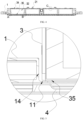
FIG. 3 is an enlarged schematic view of a region E inFIG. 2 ; -
FIG. 4 is still another schematic structural diagram of a battery pack according to some embodiments of the present disclosure; -
FIG. 5 is an enlarged schematic view of a region A inFIG. 4 ; -
FIG. 6 is an enlarged schematic view of a region B inFIG. 4 ; -
FIG. 7 is an enlarged schematic view of a region C inFIG. 4 . - List of reference signs: 1. Housing; 11. Bearing part; 12. Bottom guard plate; 13. Support frame; 14. Sidewall; 15. Base; 2. Pressure relief assembly; 21. Pressure relief pipe; 22. Weakened portion; 23. Trigger channel; 24. Trigger pad; 25. Pressing edge; 3. Cell group; 31. Explosion-proof valve; 32. Cell; 33. Structural member; 34. First side; 35. Second side; 4. Liquid cooling plate; 41. Cooling chamber; 42. Support member; 43. Avoidance recess part.
- In the description of the present disclosure, it is to be noted that orientations or position relationships indicated by the terms "upper", "lower", "front", "rear", "left", "right", "vertical", "horizontal", "top", "bottom", "inside", "outside", and the like, are based on orientations or position relationships illustrated in the drawings. The terms are used to facilitate and simplify the description of the present disclosure, rather than indicate or imply that the devices or elements referred to herein are required to have specific orientations or be constructed or operate in the specific orientations. Accordingly, the terms should not be construed as limiting the present disclosure.
- In the present disclosure, the
first side 34 refers to a top of thecell group 3 in a vertical direction, and thesecond side 35 refers to a bottom of thecell group 3 in the vertical direction. - Referring to
FIGS. 1 ,2 ,3 ,4 ,5 ,6 , and7 , in embodiments of the present disclosure, a battery pack includes ahousing 1, apressure relief assembly 2, aliquid cooling plate 4, and a plurality ofcell groups 3. In some embodiments, thecell group 3 includes a plurality ofcells 32; apressure relief assembly 2 connected to thehousing 1 and opposite to the explosion-proof valve 31 of thecell 32, thepressure relief assembly 2 presses against thefirst side 34 of thecell group 3; aliquid cooling plate 4 connected to thehousing 1 and abutting against thesecond side 35 of thecell group 3, thesecond side 35 is opposite to thefirst side 34, theliquid cooling plate 4 is provided with asupport member 42 located at the junction of twoadjacent cell groups 3, and one side of thesupport member 42 supports thesecond side 35 of one of the twoadjacent cell groups 3, and the other side of thesupport member 42 supports thesecond side 35 of another of the twoadjacent cell groups 3. In some embodiments, by providing thesupport member 42 on theliquid cooling plate 4 to support the twoadjacent cell groups 3 at the same time, theliquid cooling plate 4 is prevented from being deformed by thecell groups 3. At the same time, thepressure relief assembly 2 is pressed against thefirst side 34 of thecell group 3, thepressure relief assembly 2 is opposed to the explosion-proof valve 31 of thecells 32, the ejection ejected from the explosion-proof valve 31 is directed by thepressure relief assembly 2, and by pressing thepressure relief assembly 2 against thecell groups 3, it is possible to avoid upward channeling phenomenon of thecell groups 3 caused by the influence of the cyclic expansion force, so that thepressure relief assembly 2, which is a pressure relief passage of thecells 32, and theliquid cooling plate 4, which is a cooling source of thecells 32, form a fixed structure of the module-less battery pack, thereby realizing the combination of the mechanical structures of thepressure relief assembly 2, theliquid cooling plate 4 and thehousing 1, optimizing the structure of the battery pack, simplifying the process, and enhancing the rigidity of the system. - In some embodiments, at least one of the
cell groups 3 is arranged below thepressure relief assembly 2 along a length direction of thepressure relief assembly 2, and thepressure relief assembly 2 is pressed against thefirst side 34 of thecell group 3 to press thecell 32 against theliquid cooling plate 4, so as to prevent upward movement of thecell 32. In an embodiment, asupport frame 13 disposed outside thecell group 3 is further included in the battery pack, an end of thesupport frame 13 is fixedly connected to aside wall 14 of thehousing 1, and thepressure relief assembly 2 is fixedly connected to thesupport frame 13. Further, abase 15 is fixedly connected between thepressure relief assembly 2 and thesupport frame 13. Specifically, the connection methods adopted by the fixed connection may be a welded connection or a bolted connection. In an embodiment, the end of thesupport frame 13 is bolted to theside wall 14 of thehousing 1, thebase 15 is bolted to thesupport frame 13, and thepressure relief assembly 2 is bolted to thebase 15. In an embodiment, thesupport frame 13 and the base 15 may be integrally formed, thepressure relief assembly 2 is bolted to thebase 15, and the end of thesupport frame 13 is bolted to theside wall 14 of thehousing 1, so that thepressure relief assembly 2 can be connected to thehousing 1 as a reinforcing structure of thehousing 1, thereby improving the strength of thehousing 1. At the same time, thepressure relief assembly 2 and the explosion-proof valve 31 of thecell 32 are opposed to each other, the ejection ejected from the explosion-proof valve 31 is directed to realize thermal electrical separation and avoid the upward channeling phenomenon of thecell groups 3 caused by the influence of the cyclic expansion force which resulting in the connection failure, so that thepressure relief assembly 2 is used as a special pressure relief channel for thermal electrical separation, and the reinforcement structure of thehousing 1 to improve the strength of thehousing 1 and realize the combination of the mechanical structures of thepressure relief assembly 2 and thehousing 1. While solving the thermal safety pressure relief of the system, the system structure is optimized, and the system rigidity is improved, so that the production cost of the module-less battery pack may be reduced, the process may be simplified, and the yield and efficiency may be improved. - Further, the plurality of the
cell groups 3 may be arranged along the length direction or the width direction of thehousing 1, and thefirst side 34 of each of thecell groups 3 is pressed against thepressure relief assembly 2. Thepressure relief assembly 2 and the explosion-proof valve 31 of thecell 32 are opposed to each other, so that the ejection ejected from the explosion-proof valve 31 is directed by thepressure relief assembly 2 to solve the problem of system thermal safety pressure relief. At the same time, thecell 32 is pressed against theliquid cooling plate 4 through thepressure relief assembly 2 to avoid upward movement of thecell 32, so that theliquid cooling plate 4 may be contacted with thecell 32 for effective cooling, and thepressure relief assembly 2 provided on the plurality ofcell groups 3 is further used as a reinforcing structure of thehousing 1, so as to improve the strength of thehousing 1 and realize the combination of the mechanical structures of thepressure relief assembly 2 and thehousing 1, thereby optimizing the system structure while solving the problem of the thermal safety pressure relief of the system and improving the system rigidity, which may reduce the production cost, simplify the process, and improve the yield and efficiency. Further, a fixing structure of the battery pack in the vertical direction is formed using thepressure relief assembly 2 pressed against thefirst side 34 of thecell group 3 and theliquid cooling plate 4 pressed against thesecond side 35 of thecell group 3, and thesupport member 42 is provided on theliquid cooling plate 4 to support the twoadjacent cell groups 3 at the same time, so that theliquid cooling plate 4 is prevented from being deformed. Therefore, the combination of the mechanical structures of thepressure relief component 2, theliquid cooling plate 4 and thehousing 1 is realized, so as to optimize the structure of the module-less battery pack, simplify the process, and enhance the rigidity of the system. - Referring to
FIG. 7 , in some embodiments, thepressure relief assembly 2 includes apressure relief pipe 21, the explosion-proof valve 31 of thecell 32 is disposed corresponding to thepressure relief pipe 21, so that the high-temperature and high-pressure ejections ejected from the explosion-proof valve 31 of thecell 32 enter thepressure relief pipe 21 and are directed along thepressure relief pipe 21 so as to avoid the damage to the peripheral components or thecell 32 caused by the sputtering of the high-temperature and high-pressure ejections onto the peripheral components or thecell 32. In an embodiment, thepressure relief pipe 21 is provided with a plurality of weakenedportions 22, and the weakenedportion 22 is disposed corresponding to the explosion-proof valve 31. In an embodiment, the explosion-proof valve 31 of thecell 32 is correspondingly arranged below the weakenedportion 22 of thepressure relief pipe 21 so that the high-temperature and high-pressure gas released when the explosion-proof valve 31 of thecell 32 is opened directly enters thepressure relief pipe 21 through the weakenedportion 22 corresponding thereto, and the weakenedportions 22 at the other positions of thepressure relief pipe 21 remain closed, thereby effectively preventing the ejections in thepressure relief pipe 21 from flowing back onto the explosion-proof valve 31 of theperipheral cell 32. Further, the weakenedportion 22 is sealingly connected to the explosion-proof valve 31 so as to prevent the high-temperature and high-pressure ejections ejected when the explosion-proof valve 31 is opened from overflowing and sputtering onto the peripheral components orcells 32, causing damage to the peripheral components orcells 32. Further, thecell 32 may be provided with a corresponding groove corresponding to thepressure relief pipe 21, and thepressure relief pipe 21 is clamped in the groove so that thepressure relief pipe 21 is more firmly connected to thecell 32. At the same time, the weakenedportion 22 of thepressure relief pipe 21 is tightly attached to the explosion-proof valve 31 of thecell group 3, or is sealingly connected to the explosion-proof valve 31 of thecell 32 through a guide member such as a pipe, so as to avoid the overflow of high-temperature and high-pressure gas discharged when the explosion-proof valve 31 is opened, and the high-temperature and high-pressure ejections discharged when the explosion-proof valve 31 is opened may be effectively guided into thepressure relief pipe 21, and is directed along thepressure relief pipe 21. - In some embodiments, the
cell group 3 is limited and fixed by a fixing structure in the vertical direction formed by theliquid cooling plate 4 and the pressure-relief pipe 21, and the plurality ofcells 32 are arranged along the length direction of the pressure-relief pipe 21 and are pressed under the pressure-relief pipe 21. When the explosion-proof valve 31 of acertain cell 32 is opened to discharge the high-temperature and high-pressure ejection, there may be a substance such as an electrolyte of thecell 32 in the ejection. Since each of thepressure relief pipes 21 is connected to the explosion-proof valves 31 of the plurality ofcells 32 at the same time, the ejection may flow along thepressure relief pipe 21 and back to the explosion-proof valves 31 of theother cells 32 after entering thepressure relief pipe 21, which causing the explosion-proof valves 31 of theother cells 32 to be polluted or opened due to the high temperature, thereby causing a chain effect. Therefore, referring toFIGS. 3 and6 , in some embodiments, atrigger channel 23 is provided between thepressure relief pipe 21 and the explosion-proof valves 31, and atrigger pad 24 is provided in thetrigger channel 23. In an embodiment, thetrigger channel 23 is formed between thecell group 3 and thepressure relief pipe 21 pressed against thefirst side 34 of thecell group 3, and thetrigger pad 24 is fitted in thetrigger channel 23. When the explosion-proof valve 31 of thecell 32 erupts, the position of thetrigger pad 24 corresponding to the explosion-proof valve 31 is broken by the ejection, and then the ejection sequentially passes through thetrigger pad 24 and the weakenedportion 22 of thepressure relief pipe 21 into thepressure relief pipe 21. Since the impact force of the explosion-proof valve 31 when the valve is opened is upward, thetrigger pads 24 at the remaining positions are not affected, and the remaining area of thetrigger channel 23 is further closed to prevent the ejection ejected from the explosion-proof valve 31 of thecell 32 from sputtering onto theperipheral cells 32 or prevent the ejection in thepressure relief pipe 21 from flowing back onto the explosion-proof valves 31 of theperipheral cells 32. Theperipheral cells 32 are thus prevented from being affected. In an embodiment, thetrigger pad 24 is made of a high-temperature resistant insulating material to prevent thetrigger pad 24 from being melted by the high-temperature ejection and to effectively block the backflow of the high-temperature ejection onto the explosion-proof valves 31 of theother cells 32. Further, thetrigger pad 24 is, for example, a mica paper. Specifically, the mica paper is fitted in thetrigger channel 23 between thepressure relief pipe 21 and the explosion-proof valve 31 so that thetrigger channel 23 is in a closed state. That is, the explosion-proof valve 31 of theadjacent cell 32 is blocked and closed by the mica paper, and thepressure relief pipe 21 and the explosion-proof valve 31 are also separated and closed by the weakenedportion 22 thereof and the mica paper, so that the ejection ejected by the explosion-proof valve 31 of theadjacent cell 32 cannot be sputtered to theperipheral cells 32, and the ejection flowing in thepressure relief pipe 21 cannot pass through thetrigger channel 23 provided with the mica paper, thereby avoiding the phenomenon that the ejection flows back onto the explosion-proof valve 31 of theperipheral cell 32. When an explosion-proof valve 31 of acertain cell 32 is opened and discharges the high-pressure and high-temperature ejection, under the impact of the ejection, the position of the mica paper corresponding to the explosion-proof valve 31 is broken by the ejection, while other areas of the mica paper are not affected and continue to separate the opened explosion-proof valve 31 from the other explosion-proof valves 31 and close the other explosion-proof valves 31. Then, the ejection breaks through the weakenedportion 22 of thepressure relief pipe 21 into thepressure relief pipe 21, and flows along thepressure relief pipe 21. Since other positions are still closed by the mica paper and the weakenedportions 22 of thepressure relief pipe 21 at the other positions are not necessarily broken, the ejection may only continue to flow along thepressure relief pipe 21 and cannot flow back to the peripheral explosion-proof valves 31, thereby effectively protecting theperipheral cell groups 3 from being affected. - In some embodiments, the sides of the
pressure relief pipe 21 extend towards thecell group 3 to form apressing edge 25 that abuts against thecell group 3. In an embodiment, both sides of thepressure relief pipe 21 extend toward thecell group 3 to form thepressing edges 25 abutting against thecell group 3 to press thebattery pack 3 and increase the rigidity of thepressure relief pipe 21 and the system, so as to prevent thecell group 3 from directly abutting against thepressure relief pipe 21 when thecell group 3 erupts, and to buffer the force between thecell group 3 and thepressure relief pipe 21. At the same time, thepressing edge 25 is capable of effectively preventing the ejection from overflowing from the side of thecell group 3, so as to prevent the ejection from thecell group 3 from affecting theperipheral cell groups 3, and the extended pressingedge 25 creates a gap between thepressure relief pipe 21 and the explosion-proof valve 31, thereby forming thetrigger channel 23, and sufficiently optimizing the structure of the module-less battery pack. - Referring to
FIGS. 2 ,3 ,4, 5 and6 , in some embodiments, theliquid cooling plate 4 is internally provided with a coolingchamber 41 for receiving a coolant. In an embodiment, ahollow cooling chamber 41 is provided inside theliquid cooling plate 4 for receiving the coolant to cool thecell group 3 provided above theliquid cooling plate 4. In an embodiment, the coolingchamber 41 may be provided with an inlet and an outlet for the coolant. In some embodiments, the coolant in the coolingchamber 41 is replaced through the inlet and the outlet of the coolingchamber 41 to ensure the cooling effect of theliquid cooling plate 4. In practical application, since the coolingchamber 41 for accommodating the coolant is provided inside theliquid cooling plate 4, the bearing capacity of theliquid cooling plate 4 is weak, and under the long-time repressing of the power supply module, theliquid cooling plate 4 is liable to be deformed, especially in the middle region of theliquid cooling plate 4, and problems such as downward depression may easily occur, the original layout of the power supply module is damaged, and the stability of the overall structure of the system is seriously affected. Therefore, thesupport member 42 for supporting thecell group 3 is provided in the coolingchamber 41. In an embodiment, thesupport member 42 may be a grid-like structure, which can support thecell group 3 without affecting the flow of the coolant in the coolingchamber 41. Further, thesupport member 42 may further form a cooling flow passage in the coolingchamber 41 of theliquid cooling plate 4, and may further define a flow path of the coolant while supporting thecell group 3 by thesupport member 42, so that theliquid cooling plate 4 has a better load-bearing capacity and a better cooling effect. Referring toFIG. 4 , in an embodiment, theside wall 14 of thehousing 1 extends toward thesecond side 35 of thecell group 3 to form a bearingpart 11. That is, one end of thecell group 3 close to theside wall 14 of thehousing 1 is supported by the bearingpart 11 extending from theside wall 14 of thehousing 1, and the remaining area of thecell group 3 is supported by thesupport member 42 provided in the coolingchamber 41, that is, the bearingpart 11 and thesupport member 42 respectively support different positions of thesecond side 35 of thecell group 3, thereby ensuring stability of the overall structure of the module-less battery pack. - In some embodiments, the
housing 1 is provided with abottom guard plate 12 at a side of thehousing 1 adjacent to thesecond side 35, and theliquid cooling plate 4 is provided between thebottom guard plate 12 and thecell group 3. In an embodiment, thebottom guard plate 12 is bolted to the side of thehousing 1 adjacent to thesecond side 35. In an embodiment, a side of thebottom guard plate 12 near thesecond side 35 is fixedly connected to one side of theliquid cooling plate 4 away from thesecond side 35. In an embodiment, the side of thebottom guard plate 12 near thesecond side 35 is fixedly connected to the side of theliquid cooling plate 4 away from thesecond side 35 by means of a friction stir welding process or is fixedly connected to the side of theliquid cooling plate 4 away from thesecond side 35 by means of a FDS process. Further, thesecond side 35 of thecell group 3 is bonded to the side of theliquid cooling plate 4 near thesecond side 35 by means of a heat conducting structure adhesive, so that thecell group 3 is fixedly connected to theliquid cooling plate 4 without affecting normal heat transfer, and a protective coating is provided at the side of theliquid cooling plate 4 near thehousing 1 to protect theliquid cooling plate 4 and prevent the introduction of external heat from the side of theliquid cooling plate 4 close to thehousing 1, affecting the cooling effect of theliquid cooling plate 4 on thecell group 3. - Referring to
FIGS. 1 ,2 ,3 ,4 ,5 ,6 and7 , in some embodiments, theadjacent cell groups 3 are bonded together by astructural member 33. Specifically, sides of theadjacent cells 32 close to each other are bonded to each other by thestructural member 33, so as to improve the stability of the overall structure. In an embodiment, thesupport member 42 is provided in the coolingchamber 41 of theliquid cooling plate 4, and is located at the junction of the twoadjacent cell groups 3, one side of thesupport member 42 supports asecond side 35 of one of the twoadjacent cell groups 3, and another side of thesupport member 42 supports asecond side 35 of another of the twoadjacent cell groups 3, that is, thesupport member 42 supports the twoadjacent cell groups 3 at the same time, so as to effectively avoid a problem such as downward depression in the middle region of theliquid cooling plate 4. At the same time, thefirst side 34 of thecell group 3 is pressed against thepressure relief assembly 2, which is opposed to the explosion-proof valve 31 of thecell 32, the ejection ejected from the explosion-proof valve 31 is directed by thepressure relief assembly 2, and by pressing thepressure relief assembly 2 against thecell groups 3, it is possible to avoid upward channeling phenomenon of thecell groups 3 caused by the influence of the cyclic expansion force, so that thepressure relief assembly 2, which is a pressure relief passage of thecells 32, and theliquid cooling plate 4, which is a cooling source of thecells 32, form a fixed structure of the battery pack, thereby realizing the combination of the mechanical structures of thepressure relief assembly 2, theliquid cooling plate 4 and thehousing 1, optimizing the structure of the battery pack, simplifying the process, and enhancing the rigidity of the system. In an embodiment, thepressure relief assembly 2 includes apressure relief pipe 21, thetrigger channel 23 is provided between thepressure relief pipe 21 and the explosion-proof valve 31 of thecell group 3, and thetrigger pad 24 is fitted in thetrigger channel 23. When the explosion-proof valve 31 of thecell 32 erupts, the position of thetrigger pad 24 corresponding to the explosion-proof valve 31 is broken by the ejection, and then the ejection passes through the weakenedportion 22 of thepressure relief pipe 21 into thepressure relief pipe 21. Since the impact force of the explosion-proof valve 31 when the valve is opened is upward, thetrigger pads 24 at the remaining positions and the weakenedportions 22 at the remaining positions of thepressure relief pipe 21 are not affected, and the remaining area of thetrigger channel 23 is further closed to prevent the ejection ejected from the explosion-proof valve 31 of thecell 32 from sputtering onto theperipheral cells 32, or prevent the ejection in thepressure relief pipe 21 from flowing back onto the explosion-proof valves 31 of theperipheral cells 32, so that theperipheral cells 32 are prevented from being affected, thereby enabling thepressure relief pipe 21 to direct the ejection ejected from the explosion-proof valve 31, and solve the problem of thermal safety pressure relief of the module-less battery pack. - Referring to
FIGS. 1 ,2 ,3 ,4 ,5 ,6 and7 , in some embodiments, theadjacent cell groups 3 are bonded together by thestructural members 33. Specifically, sides of theadjacent cells 32 close to each other are bonded to each other by thestructural member 33, so as to improve the stability of the overall structure. In an embodiment, theliquid cooling plate 4 is provided with anavoidance recess part 43, thesupport member 42 is embedded in theavoidance recess part 43, thesupport member 42 is located at the junction of the twoadjacent cell groups 3, one side of thesupport member 42 supports asecond side 35 of one of the twoadjacent cell groups 3, and another side of thesupport member 42 supports asecond side 35 of another of the twoadjacent cell groups 3, that is, thesupport member 42 supports the twoadjacent cell groups 3 at the same time, so as to effectively avoid a problem such as downward depression of theliquid cooling plate 4. At the same time, thefirst side 34 of thecell group 3 is pressed against thepressure relief assembly 2, which is opposed to the explosion-proof valve 31 of thecell 32, the ejection ejected from the explosion-proof valve 31 is directed by thepressure relief assembly 2, and by pressing thepressure relief assembly 2 against thecell groups 3, it is possible to avoid upward channeling phenomenon of thecell groups 3 caused by the influence of the cyclic expansion force, so that thepressure relief assembly 2, which is a pressure relief passage of thecells 32, and theliquid cooling plate 4, which is a cooling source of thecells 32, form a fixed structure of the battery pack, thereby realizing the combination of the mechanical structures of thepressure relief assembly 2, theliquid cooling plate 4 and thehousing 1, optimizing the structure of the battery pack, simplifying the process, and enhancing the rigidity of the system. In an embodiment, thepressure relief assembly 2 includes apressure relief pipe 21, thetrigger channel 23 is provided between thepressure relief pipe 21 and the explosion-proof valve 31 of thecell group 3, and thetrigger pad 24 is fitted in thetrigger channel 23. When the explosion-proof valve 31 of thecell 32 erupts, the position of thetrigger pad 24 corresponding to the explosion-proof valve 31 is broken by the ejection, and then the ejection passes through the weakenedportion 22 of thepressure relief pipe 21 into thepressure relief pipe 21. Since the impact force of the explosion-proof valve 31 when the valve is opened is upward, thetrigger pads 24 at the remaining positions and the weakenedportions 22 at the remaining positions of thepressure relief pipe 21 are not affected, and the remaining area of thetrigger channel 23 is further closed to prevent the ejection ejected from the explosion-proof valve 31 of thecell 32 from sputtering onto theperipheral cells 32, or prevent the ejection in thepressure relief pipe 21 from flowing back onto the explosion-proof valves 31 of theperipheral cells 32, so that theperipheral cells 32 are prevented from being affected, thereby enabling thepressure relief pipe 21 to direct the ejection ejected from the explosion-proof valve 31, and solve the problem of thermal safety pressure relief of the module-less battery pack.
Claims (15)
- A battery pack, characterized in that the battery pack comprises:a housing (1);a plurality of cell groups (3) comprising a plurality of cells (32);a pressure relief assembly (2) connected to the housing (1) and opposite to an explosion-proof valve (31) of each of the cells (32), wherein the pressure relief assembly (2) presses against first sides (34) of the cell groups (3); anda liquid cooling plate (4) connected to the housing (1) and abutting against second sides (35) of the cell groups (3), wherein the second sides (35) are opposite to the first sides (34), the liquid cooling plate (4) is provided with a support member (42), the support member (42) is located at a junction of two adjacent cell groups (3), and one side of the support member (42) supports a second side (35) of one of the two adjacent cell groups (3), another side of the support member (42) supports a second side (35) of another of the two adjacent cell groups (3).
- The battery pack according to claim 1, characterized in that the pressure relief assembly (2) comprises a pressure relief pipe (21), the pressure relief pipe (21) is provided with a weakened portion (22), the weakened portion (22) is arranged opposite to the explosion-proof valve (31).
- The battery pack according to claim 2, characterized in that a trigger channel (23) is formed between the pressure relief pipe (21) and the explosion-proof valve (31), and a trigger pad (24) is fitted into the trigger channel (23).
- The battery pack according to claim 3, characterized in that the trigger pad (24) is made of a high-temperature resistant insulating material.
- The battery pack according to claim 2, characterized in that a side of the pressure relief pipe (21) extends toward the cell groups (3) to form a pressing edge (25) abutting against the cell groups (3).
- The battery pack according to any one of claims 1 to 5, characterized in that adjacent cells (32) are bonded together by a structural member (33).
- The battery pack according to any one of claims 1 to 5, characterized in that the liquid cooling plate (4) is internally provided with a cooling chamber (41) for receiving a coolant.
- The battery pack according to claim 7, characterized in that the support member (42) is provided in the cooling chamber (41).
- The battery pack according to claim 8, characterized in that the support member is a grid-like structure.
- The battery pack according to claim 7, characterized in that the liquid cooling plate (4) is provided with an avoidance recess part (43), and the support member (42) is fitted in the avoidance recess part (43).
- The battery pack according to claim 1, characterized in that a side wall (14) of the housing (1) extends toward the second sides (35) of the cell groups (3) to form a bearing part (11), the bearing part (11) and the support member (42) support different positions of the second sides (35) of the cell groups (3).
- The battery pack according to claim 1, characterized in that the battery pack further comprising a support frame (13) provided at outside of the cell groups (3), an end of the support frame (13) is fixedly connected to a side wall (14) of the housing(1), and the pressure relief assembly (2) is fixedly connected to the support frame (13).
- The battery pack according to claim 12, characterized in that a base (15) is fixedly connected between the pressure relief assembly (2) and the support frame (13).
- The battery pack according to claim 1, characterized in that a bottom guard plate (12) is provided at a side of the housing (1) close to the second sides (35), and the liquid cooling plate (4) is provided between the bottom guard plate (12) and the cell groups (3).
- The battery pack according to claim 14, characterized in that a side of the bottom guard plate (12) close to the second sides (35) is fixedly connected to a side of the liquid cooling plate (4) away from the second sides (35).
Applications Claiming Priority (2)
| Application Number | Priority Date | Filing Date | Title |
|---|---|---|---|
| CN202310730179.5A CN116826270A (en) | 2023-06-19 | 2023-06-19 | a battery pack |
| CN202321571433.3U CN220042068U (en) | 2023-06-19 | 2023-06-19 | Battery pack |
Publications (1)
| Publication Number | Publication Date |
|---|---|
| EP4481891A1 true EP4481891A1 (en) | 2024-12-25 |
Family
ID=88974265
Family Applications (1)
| Application Number | Title | Priority Date | Filing Date |
|---|---|---|---|
| EP23213582.2A Pending EP4481891A1 (en) | 2023-06-19 | 2023-12-01 | Battery pack |
Country Status (5)
| Country | Link |
|---|---|
| US (1) | US20240097271A1 (en) |
| EP (1) | EP4481891A1 (en) |
| JP (1) | JP7590527B2 (en) |
| KR (1) | KR102944761B1 (en) |
| WO (1) | WO2024259751A1 (en) |
Citations (4)
| Publication number | Priority date | Publication date | Assignee | Title |
|---|---|---|---|---|
| JP2015133169A (en) * | 2012-04-27 | 2015-07-23 | 三洋電機株式会社 | Power supply device, and vehicle and power storage device provided with the same |
| DE102020128756A1 (en) * | 2020-11-02 | 2022-05-05 | Bayerische Motoren Werke Aktiengesellschaft | Battery with a protective element and motor vehicle |
| US20220320677A1 (en) * | 2020-11-25 | 2022-10-06 | Contemporary Amperex Technology Co., Limited | Battery cell and manufacturing method and system therefor, battery and electric device |
| KR20230008962A (en) * | 2021-07-07 | 2023-01-17 | 주식회사 엘지에너지솔루션 | Battery pack having a pack case with intergrated cooling pins |
Family Cites Families (18)
| Publication number | Priority date | Publication date | Assignee | Title |
|---|---|---|---|---|
| JP2015111493A (en) | 2012-03-28 | 2015-06-18 | 三洋電機株式会社 | Power supply device, and vehicle and power storage device comprising the same |
| JP6174381B2 (en) | 2013-06-06 | 2017-08-02 | 日立オートモティブシステムズ株式会社 | Storage block and storage module |
| JP2015018706A (en) | 2013-07-11 | 2015-01-29 | 株式会社豊田自動織機 | Power storage device module |
| JP6536497B2 (en) | 2016-06-30 | 2019-07-03 | トヨタ自動車株式会社 | Battery pack |
| US11142058B2 (en) * | 2017-07-26 | 2021-10-12 | Autotech Engineering S.L. | Battery box floor for electric vehicles and corresponding vehicle body |
| KR102771554B1 (en) * | 2019-08-07 | 2025-02-20 | 주식회사 엘지에너지솔루션 | Battery pack that incorporates a battery module and a rigid beam and employs a reverse assembly |
| CN211404606U (en) * | 2020-03-20 | 2020-09-01 | 中航锂电(洛阳)有限公司 | A safety structure of a battery module and a battery pack |
| CN212033078U (en) * | 2020-05-11 | 2020-11-27 | 恒大新能源技术(深圳)有限公司 | Battery packs and vehicles |
| CN114175363B (en) * | 2020-07-10 | 2024-02-20 | 宁德时代新能源科技股份有限公司 | Batteries and related devices, preparation methods and preparation equipment |
| CN214254595U (en) * | 2020-12-29 | 2021-09-21 | 蜂巢能源科技有限公司 | Battery pack case and battery pack |
| CN215299401U (en) * | 2021-04-16 | 2021-12-24 | 北京车和家信息技术有限公司 | Battery package buffer, battery package and vehicle |
| CA3227987A1 (en) | 2021-08-06 | 2023-02-09 | Piaopiao YANG | Case of battery, battery, power consumption device, and method and device for manufacturing battery |
| CN216488307U (en) * | 2021-11-16 | 2022-05-10 | 宁德时代新能源科技股份有限公司 | Harness Board Assemblies, Battery Packs, and Consumers for Battery Packs |
| CN216597740U (en) * | 2021-12-27 | 2022-05-24 | 蜂巢能源科技股份有限公司 | Battery pack |
| CN217158339U (en) * | 2022-04-14 | 2022-08-09 | 宁德时代新能源科技股份有限公司 | Cooling device, battery and electric device |
| CN218632324U (en) | 2022-06-28 | 2023-03-14 | 小米汽车科技有限公司 | Battery pack and vehicle |
| CN116093517A (en) * | 2022-11-07 | 2023-05-09 | 湖北亿纬动力有限公司 | A battery pack and vehicle |
| CN116093491A (en) | 2023-02-21 | 2023-05-09 | 江苏正力新能电池技术有限公司 | Battery cell |
-
2023
- 2023-07-10 WO PCT/CN2023/106520 patent/WO2024259751A1/en not_active Ceased
- 2023-10-11 KR KR1020230135215A patent/KR102944761B1/en active Active
- 2023-10-12 JP JP2023176750A patent/JP7590527B2/en active Active
- 2023-11-28 US US18/520,926 patent/US20240097271A1/en active Pending
- 2023-12-01 EP EP23213582.2A patent/EP4481891A1/en active Pending
Patent Citations (4)
| Publication number | Priority date | Publication date | Assignee | Title |
|---|---|---|---|---|
| JP2015133169A (en) * | 2012-04-27 | 2015-07-23 | 三洋電機株式会社 | Power supply device, and vehicle and power storage device provided with the same |
| DE102020128756A1 (en) * | 2020-11-02 | 2022-05-05 | Bayerische Motoren Werke Aktiengesellschaft | Battery with a protective element and motor vehicle |
| US20220320677A1 (en) * | 2020-11-25 | 2022-10-06 | Contemporary Amperex Technology Co., Limited | Battery cell and manufacturing method and system therefor, battery and electric device |
| KR20230008962A (en) * | 2021-07-07 | 2023-01-17 | 주식회사 엘지에너지솔루션 | Battery pack having a pack case with intergrated cooling pins |
Also Published As
| Publication number | Publication date |
|---|---|
| KR20230158431A (en) | 2023-11-20 |
| KR102944761B1 (en) | 2026-03-30 |
| JP2023174806A (en) | 2023-12-08 |
| JP7590527B2 (en) | 2024-11-26 |
| WO2024259751A1 (en) | 2024-12-26 |
| US20240097271A1 (en) | 2024-03-21 |
Similar Documents
| Publication | Publication Date | Title |
|---|---|---|
| CN220042068U (en) | Battery pack | |
| KR102646854B1 (en) | Battery module | |
| CN212517314U (en) | High-rigidity light-weight battery pack structure | |
| US12565091B2 (en) | Vehicle and battery pack thereof | |
| KR101749190B1 (en) | Battery module | |
| EP4425673A1 (en) | Power battery pack and electric device | |
| US20220149453A1 (en) | Cooling device for power battery system, power battery system and vehicle | |
| JP7556985B2 (en) | Battery packs and electric vehicles | |
| CN218101448U (en) | Cooling exhaust components and battery modules | |
| US20250038300A1 (en) | Battery cooling system, battery pack, and vehicle | |
| US20240234940A9 (en) | Battery assemblies | |
| JP2023528962A (en) | battery pack and vehicle | |
| CN212113812U (en) | Battery box and electric automobile | |
| CN112151699A (en) | Battery packs and vehicles | |
| EP4641767A1 (en) | Battery pack and electric apparatus | |
| EP4481891A1 (en) | Battery pack | |
| KR102858414B1 (en) | Cell-case unit and battery module having thereof | |
| WO2025119397A1 (en) | Battery module assembly, battery pack, and vehicle | |
| KR20240071813A (en) | Battery module and battery pack including the same | |
| CN221239698U (en) | Battery pack | |
| CN220652266U (en) | Battery pack and new energy automobile | |
| CN116826270A (en) | a battery pack | |
| CN218385553U (en) | Beam assembly and battery pack in groups | |
| CN218123547U (en) | Energy storage assembly and energy storage bag | |
| KR20240098779A (en) | Battery pack suitable for thermal propagation delay |
Legal Events
| Date | Code | Title | Description |
|---|---|---|---|
| PUAI | Public reference made under article 153(3) epc to a published international application that has entered the european phase |
Free format text: ORIGINAL CODE: 0009012 |
|
| STAA | Information on the status of an ep patent application or granted ep patent |
Free format text: STATUS: REQUEST FOR EXAMINATION WAS MADE |
|
| 17P | Request for examination filed |
Effective date: 20231201 |
|
| AK | Designated contracting states |
Kind code of ref document: A1 Designated state(s): AL AT BE BG CH CY CZ DE DK EE ES FI FR GB GR HR HU IE IS IT LI LT LU LV MC ME MK MT NL NO PL PT RO RS SE SI SK SM TR |