EP4481785A1 - Switching device - Google Patents
Switching device Download PDFInfo
- Publication number
- EP4481785A1 EP4481785A1 EP23180343.8A EP23180343A EP4481785A1 EP 4481785 A1 EP4481785 A1 EP 4481785A1 EP 23180343 A EP23180343 A EP 23180343A EP 4481785 A1 EP4481785 A1 EP 4481785A1
- Authority
- EP
- European Patent Office
- Prior art keywords
- contact element
- contact
- switching device
- axial direction
- intermediate state
- Prior art date
- Legal status (The legal status is an assumption and is not a legal conclusion. Google has not performed a legal analysis and makes no representation as to the accuracy of the status listed.)
- Pending
Links
Images



Classifications
-
- H—ELECTRICITY
- H01—ELECTRIC ELEMENTS
- H01H—ELECTRIC SWITCHES; RELAYS; SELECTORS; EMERGENCY PROTECTIVE DEVICES
- H01H33/00—High-tension or heavy-current switches with arc-extinguishing or arc-preventing means
- H01H33/02—Details
- H01H33/04—Means for extinguishing or preventing arc between current-carrying parts
- H01H33/12—Auxiliary contacts on to which the arc is transferred from the main contacts
- H01H33/121—Load break switches
- H01H33/122—Load break switches both breaker and sectionaliser being enclosed, e.g. in SF6-filled container
-
- H—ELECTRICITY
- H01—ELECTRIC ELEMENTS
- H01H—ELECTRIC SWITCHES; RELAYS; SELECTORS; EMERGENCY PROTECTIVE DEVICES
- H01H33/00—High-tension or heavy-current switches with arc-extinguishing or arc-preventing means
- H01H33/02—Details
- H01H33/28—Power arrangements internal to the switch for operating the driving mechanism
- H01H33/40—Power arrangements internal to the switch for operating the driving mechanism using spring motor
-
- H—ELECTRICITY
- H01—ELECTRIC ELEMENTS
- H01H—ELECTRIC SWITCHES; RELAYS; SELECTORS; EMERGENCY PROTECTIVE DEVICES
- H01H33/00—High-tension or heavy-current switches with arc-extinguishing or arc-preventing means
- H01H33/70—Switches with separate means for directing, obtaining, or increasing flow of arc-extinguishing fluid
-
- H—ELECTRICITY
- H01—ELECTRIC ELEMENTS
- H01H—ELECTRIC SWITCHES; RELAYS; SELECTORS; EMERGENCY PROTECTIVE DEVICES
- H01H1/00—Contacts
- H01H1/12—Contacts characterised by the manner in which co-operating contacts engage
- H01H1/14—Contacts characterised by the manner in which co-operating contacts engage by abutting
-
- H—ELECTRICITY
- H01—ELECTRIC ELEMENTS
- H01H—ELECTRIC SWITCHES; RELAYS; SELECTORS; EMERGENCY PROTECTIVE DEVICES
- H01H1/00—Contacts
- H01H1/12—Contacts characterised by the manner in which co-operating contacts engage
- H01H1/36—Contacts characterised by the manner in which co-operating contacts engage by sliding
- H01H1/38—Plug-and-socket contacts
- H01H1/385—Contact arrangements for high voltage gas blast circuit breakers
-
- H—ELECTRICITY
- H01—ELECTRIC ELEMENTS
- H01H—ELECTRIC SWITCHES; RELAYS; SELECTORS; EMERGENCY PROTECTIVE DEVICES
- H01H33/00—High-tension or heavy-current switches with arc-extinguishing or arc-preventing means
- H01H33/02—Details
- H01H2033/028—Details the cooperating contacts being both actuated simultaneously in opposite directions
Definitions
- the present disclosure relates to a switching device, particularly to a switching device for high voltage applications.
- One object to be achieved is to provide a switching device with high breaking capabilities.
- the switching device comprises a base element, a first contact element, a second contact element and at least one drive member.
- the first and the second contact element are arranged movably relative to each other and relative to the base element along an axis.
- the switching device is configured to switch from a closed state into an open state.
- the switching device is configured such that, during switching from the closed to the open state, the switching device adopts a first intermediate state in which the first and the second contact element are in electrical contact and are commonly accelerated by the at least one drive member relative to the base element in a first axial direction.
- the switching device then switches from the first intermediate state into a second intermediate state in which the first and the second contact element are separated and in which the second contact element continues to move relative to the base element and additionally moves relative to the first contact element in the first axial direction.
- the present invention is, inter alia, based on the idea to design the kinematics of the switching device such that the two contact elements are simultaneously accelerated while they are still in contact.
- an instantaneous high-speed of separation is present at the point of separation, i.e. when switching from the first intermediate state into the second intermediate state.
- the separation starts with a high relative speed of the contact elements. This leads to high breaking capabilities for very high electromagnetically and electrostatically induced currents and very high bus transfer currents.
- the switching device is, in particular, suited for high voltage applications and/or high current applications.
- the switching device is configured for electric currents of at least 100 A or at least 1000 A flowing between the first and the second contact element.
- the switching device may be a so-called disconnector switch or a so-called earthing switch.
- the base element may be a housing in which the first and the second contact element as well as the at least one drive member are located.
- the housing may be filled with a gas, particularly quenching gas or insulation gas, like SF6 or any alternative.
- the axis along which the first and the second contact element are movable relative to each other and relative to the base element is also called “longitudinal axis” or “separation axis” or “breaking axis”.
- the first and/or the second contact element may be formed rotationally-symmetrically with respect to this axis.
- Axial directions are herein defined as directions parallel to this axis.
- the first and/or the second contact element may be formed as a hollow body, e.g. as an elongated hollow body elongated along the (separation) axis, like a sleeve-shaped body.
- Each of the first and the second contact elements may comprise a contact portion facing in an axial direction.
- the contact portions of the two contact elements face each other and are in direct electrical and mechanical contact in the first intermediate state and, optionally, also in the closed state, i.e. they adjoin each other in these states.
- the contact portions may be formed as lids closing the hollow contact elements in axial direction.
- the closed and open states of the switching device are, in particular, resting states in which the contact elements neither move relative to each other nor relative to the base element.
- the switching device comprises input and output terminals. In the closed state, the switching device enables a current flow from the input terminals to the output terminals wherein, in the open state, a current flow from the input terminals to the output terminals is disabled.
- the first and the second contact elements are electrically connected to each other in the closed state, e.g. adjoin each other, wherein the first and the second contact elements are electrically and physically separated from each other in the open state.
- the contact elements In the first and the second intermediate state, at least one of the contact elements is moving relative to the base element.
- the contact elements are commonly accelerated relative to the base element while they are continuously in electrical contact with each other, e.g. adjoin each other.
- the magnitude and direction of acceleration is the same for both contact elements in the first intermediate state. "Accelerated" means that the velocity is increased.
- the first and second contact element are continuously accelerated.
- the second intermediate state is, in particular, the state which immediately follows the first intermediate state.
- the separation of the contact elements or the switch from the first to the second intermediate state, respectively happens at a moment in time in which the two contact elements are commonly accelerated.
- an arc may form between the first and the second contact elements after the separation. That is, in the second intermediate state, the arc may be formed between the first and the second contact elements, particularly between the contact portions thereof. A main extension direction of this arc is then in axial direction, for example.
- the switching device comprises two drive members.
- a drive member is herein defined as a member for moving at least one of the contact elements in an axial direction by exerting force onto the contact element.
- the drive members may be realized by springs or hydraulic members or other means, like pneumatic, magnetic or electro-magnetic means.
- the second contact element is arranged downstream of the first contact element in the first axial direction.
- the first contact element follows the second contact element during the common acceleration and common movement in the first axial direction.
- the common acceleration of the first and the second contact element in the first axial direction during the first intermediate state is caused by a first drive member and a second drive member.
- the first drive member thereby pushes the first contact element against the second contact element in the first axial direction.
- the second drive member exerts force onto the second contact element in the first axial direction.
- the second drive member may pull the second contact element in the first axial direction.
- the first drive member may be received in the hollow first contact element and may push against an inner surface of the above-mentioned contact portion of the first contact element.
- the second drive member is arranged in the hollow second contact element and may push at an inner surface of the second contact element. This inner surface faces in the direction of the first contact element and is located at an (longitudinal) end of the second contact element facing away from the first contact element.
- the forces exerted by the first and the second drive member are chosen such that the first contact element is continuously pushed against the second contact element.
- the acceleration of the second contact element solely induced by the second drive member is smaller than the acceleration of the first contact element induced by the first drive member so that, in the first intermediate state, the first and the second contact elements feel the same acceleration and continuously stay in electrical contact.
- the contact portions of the contact elements stay in direct contact with each other, for example.
- the second contact element is further accelerated by the at least one drive member relative to the base element and additionally relative to the first contact element in the first axial direction, at least at the beginning of the second intermediate state. For example, immediately after switching from the first into the second intermediate state, the second contact element is further accelerated relative to the base element and also relative to the first contact element. In other words, when switching from the first intermediate state into the second intermediate state, i.e. at the moment of contact separation, the acceleration of the second contact element in the first axial direction is greater than the acceleration of the first contact element in the first axial direction.
- the further acceleration of the second contact element is then, for example, only induced by the second drive member.
- the first drive member would then not further contribute to the further acceleration of the second contact element.
- switching from the first into the second intermediate state is induced by slowing down, particularly stopping, the movement of the first contact element relative to the base element in the first axial direction. This may be done by means of a stop.
- the movement of the second contact element in the first axial direction is further enabled or maintained, respectively, i.e. the stop does not influence the movement of the second contact element.
- the switch from the first into the second intermediate state is induced by a portion, e.g. a protrusion, of the first contact element abutting/hitting against the stop. Movement of the stop in the first axial direction may be disabled in the first intermediate state.
- the hit of the first contact element against the stop blocks a further movement of the first contact element in the first axial direction.
- the switching device is further configured such that, during switching from the closed to the open state, the switching device adopts a third intermediate state before the first intermediate state.
- the third intermediate state the first and the second contact element are commonly moved relative to the base element in a second axial direction.
- the second axial direction is opposite to the first axial direction.
- the switching device then switches from the third into the first intermediate state.
- the switching from the third into the first intermediate state happens, particularly, automatically.
- the first intermediate state follows immediately after the third intermediate state.
- the first and the second contact element may be continuously in electrical contact with each other, e.g. adjoin each other.
- the above-mentioned contact portions of the first and the second contact element may adjoin each other in the third intermediate state.
- the at least one drive member is loaded in the third intermediate state so that it accumulates potential energy.
- the first and/or the second drive member are loaded during the third intermediate state and thereby accumulate potential energy.
- the at least one loaded drive member releases at least some of the accumulated potential energy in the first intermediate state.
- the released potential energy is then used to accelerate the first and the second contact element in the first axial direction.
- the loaded first and/or the loaded second drive member release at least some of their accumulated potential energy in the first intermediate state.
- Firing of the at least one drive member i.e. the start of releasing energy, may happen automatically when switching from the third into the first intermediate state.
- the at least one drive member is a spring.
- the first and the second drive member are both springs, herein therefore also called “first and second spring”.
- the at least one drive member in the form of a spring is biased in the third intermediate state.
- the first and the second spring are both compressed.
- the switching device further comprises a third contact element.
- the third contact element may be formed hollow and/or elongated along the (separation) axis.
- the third contact element is sleeve-shaped or cylindrically shaped, respectively.
- the first contact element may be at least partially received in the third contact element.
- the first drive member may be received at least partially in the third contact element.
- the third contact element may be open in order to enable the first contact element to be partially ejected from the third contact element in the first exit direction and/or in order to enable the first contact element to be retracted into the third contact element in the second axial direction.
- the third contact element is axially movable relative to the base element and relative to the first as well as to the second contact element.
- the third contact element may be electrically connected to the first contact element, e.g. permanently. Sliding contacts, like spiral contacts, between the first and the third contact element may be provided in order to maintain the electric contact during relative movement of the first and the third contact element.
- the switching device is configured such that an electric current flows through the third contact element in the closed state and during normal operation. That is, the current from the input terminal to the output terminal flows through the third contact element. For example, no or little electric current flows through the first and/or the second contact element during normal operation and in the closed state.
- the third contact element moves in the second axial direction relative to the base element and/or relative to the first and the second contact element. This movement in the second axial direction may be maintained, at least temporarily, in the second intermediate state.
- first and the second contact element are coupled to the third contact element in the third intermediate state.
- Coupled means, in particular, mechanically coupled or magnetically coupled, for example.
- a drive force pointing in the second axial direction is exerted on to the third contact element in the third intermediate state.
- This and the coupling of the first and the second contact element to the third contact element causes a common movement of the first, the second and the third contact element in the second axial direction.
- the drive force and the coupling are such that the first, the second and the third contact element are commonly moved in the second axial direction.
- the drive force and the coupling are such that a movement of the first and the second contact element relative to the base element and relative to the third contact element in the first axial direction driven by the at least one drive member is disabled in the third intermediate state.
- the drive force and the coupling are such strong that they withstand a force of the at least one (loaded/biased) drive member acting on the first and the second contact element in the first axial direction and even results in a movement of the first and the second contact element in the second axial direction.
- the switching device is configured such that, when switching from the third intermediate state into the first intermediate state, the coupling of the first and the second contact element to the third contact element is released so that the common acceleration of the first and the second contact element relative to the base element in the first axial direction and driven by the at least one drive member is enabled.
- the release may happen automatically when switching from the third into the first intermediate state.
- the drive force may then be further exerted onto the third contact element so that this further moves in the second axial direction.
- the coupling of the first and the second contact element to the third contact element is realized by coupling elements which are coupled with each other.
- the coupling elements may be frictionally and/or form-fittingly coupled. Frictional coupling can also be called “force-fitting coupling”.
- the coupling may be a pure frictional coupling.
- the coupling may be realized by the coupling elements engaging with each other.
- one of the coupling elements is part of the third contact element and another one of the coupling elements is part of the first and/or the second contact element.
- the coupling element of the third contact element may be a protrusion.
- the coupling element of the first and/or the second contact element may comprise one or more elastic elements.
- the elastic elements may form a so-called finger cage.
- the one or more elastic elements When engaged with each other, the one or more elastic elements may be biased and pressed against the protrusion, e.g. at least partially in radial direction.
- Radial directions are herein defined with respect to the (separation) axis. This means, radial directions are direction perpendicularly towards or away from the axis.
- the drive force acts on the first and the second contact element only via the coupling of the coupling elements.
- the drive force exerted onto the third contact element is transferred to the first and the second contact element only via the coupling between the coupling elements.
- the coupling force between the coupling elements is larger than a tractive force on the coupling elements so that the first and the second contact element are pulled along with the third contact element.
- the tractive force tries to move the coupling elements relative to each other in order to release the coupling.
- the coupling force which is also called “holding force”
- the coupling via the coupling elements is maintained.
- release of the coupling i.e. switching from the third into the first intermediate state, is induced by the tractive force becoming larger than the coupling force.
- release of the coupling is induced by stopping, particularly blocking, the movement of the first and the second contact elements relative to the base element in the second axial direction with help of a stop.
- the movement of the third contact element in the second axial direction may, however, still be enabled.
- the first or the second contact element e.g. a protrusion thereof, abuts/hits against the stop.
- the stop may be fixed in position relative to the base element. By abutting/hitting against the stop, movement of the respective contact element in the second axial direction is blocked. The tractive force on the coupling elements then becomes larger than the coupling force and the coupling is released.
- the switching device comprises further drive member, herein also called “third drive member”.
- the further drive member is configured to exert the drive force onto the third contact element in the third intermediate state.
- This third drive member is, in particular, different from the at least one (first and/or second) drive member causing the common acceleration of the first and second contact element.
- the third drive member may comprise an electric motor.
- the switching device comprises a reservoir for receiving gas, like a quenching gas or insulation gas.
- the gas may be SF6.
- the switching device is configured to inject gas from the reservoir into the space between the separated first and second contact element in the second intermediate state.
- the flow direction of the injected gas is in an axial direction.
- the gas is injected such so that a flow sheath of the injected gas is formed which is configured to enclose an arc forming between the first and the second contact elements.
- the (separation) axis runs through the flow sheath, particularly centrally through the flow sheath.
- a last contact point between the first and the second contact element is enclosed by the flow sheath.
- the last contact point is, in particular, formed between the above-mentioned contact portions of the first of the second contact element.
- At least one exit channel leads from the reservoir to the space between the separated first and second contact elements in the second intermediate state.
- the reservoir is formed between a surface which is axially fixed with respect to the base element and a further surface which is axially fixed with respect to the second contact element. In the second intermediate state, the surface and the further surface approximate each other whereby the volume of the reservoir is reduced so that a gas in the reservoir is pressed through the exit channel and injected into the space.
- the reservoir is formed in the hollow second contact element.
- the further surface may be formed by an inner surface of the contact portion of the second contact element, said inner surface being located in the second contact element and facing away from the first contact element.
- the exit channel may extend through the contact portion of the second contact element.
- the surface which is axially fixed to the base element may be formed by a plunger which is received in the hollow second contact element.
- the surface may face towards the first contact element.
- One end of the second drive member may be fixed to the plunger.
- At least one entry channel leads from an outside volume of the reservoir into the reservoir.
- the switching device is configured such that gas from the outside volume flows through the at least one entry channel into the reservoir during the third intermediate state.
- the surface and the further surface between which the reservoir is formed move away from each other so that the volume of the reservoir is increased and gas from the outside is sucked into the reservoir via the entry channel(s).
- the switching device comprises a first and a second contact element which are movable relative to each other along an axis and a reservoir for receiving a gas.
- the switching device is configured to switch from a closed state into an open state.
- the switching device is configured such that, during switching from the open state to the closed state, the first and the second contact elements are electrically separated from each other by moving them relative to each and away from each other along the axis.
- gas from the reservoir is injected into the space between the separated first and second contact elements while they move relative to each other, wherein a flow direction of the injected gas is in an axial direction so that a flow sheath of gas is formed which is configured to enclose an arc forming between the first and second contact elements.
- such an arc forms between the contact elements, particularly between the contact portions thereof.
- the sheath of gas helps to enclose the arc and prevent it from reaching parts other than the contact elements, it particularly helps to extinguish the arc.
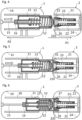
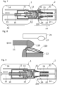
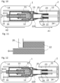
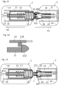
- Figures 1 to 15 , 17, 18 and 20 show different positions during operation of an exemplary embodiment of the switching device
- Figures 16 and 19 show different exemplary embodiments of the second contact element
- Figure 21 shows the operation of an exemplary embodiment of the switching device with the help of a graph.
- FIG. 1 shows an exemplary embodiment of the switching device 100 in an open state of the switching device.
- the switching device 100 comprises a first assembly 1 and a second assembly 2, which are electrically separated and isolated from each other. Both assemblies 1, 2 are arranged in a base element 4, namely a housing element 4, which is filled with gas, e.g. a quenching gas or insulation gas, respectively.
- the gas may be SF6.
- the first assembly 1 is electrically connected to conductors 5, which reach from the interior of the housing element 4 through the housing element 4 to the outside, where the conductors 6 form a terminal, e.g. an input terminal.
- the second assembly 6 is electrically connected to conductors 6, which also reach from the interior of the housing element 4 through the housing element 4 to the outside, where the conductors 6 form a terminal, e.g. an output terminal.
- an electric motor 3 is arranged outside of the housing element 4.
- the electric motor 3 is coupled to the first assembly 1 by means of a spindle 15. This will be explained in more detail further below.
- Figure 1 further indicates an axis A which runs from the left to the right and is herein also called “longitudinal axis” or “separation axis", respectively. Moreover, two axial directions are indicated, namely a first axial direction A1 pointing from the left to the right and a second exit direction A2 pointing from the right to the left.
- FIG. 2 shows the two assemblies 1, 2 of figure 1 in more detail.
- the first assembly 1 comprises a first contact element 12, also called “arcing contact 12" or “first arcing contact 12" in the following.
- the first assembly 1 further comprises a third contact element 11, also called “moving contact shield 11” in the following.
- the moving contact shield 11 is a hollow, elongated, sleeve-shaped body which extends in axial direction A1, A2.
- the arcing contact 12 is arranged inside the moving contact shield 11 and is also formed hollow, elongated and sleeve-shaped.
- the arcing contact 12 comprises a contact portion 125 in the form of a lid at its longitudinal end closest to the second assembly 2.
- the lid 125 closes the sleeve-shaped body of the arcing contact 12 and projects out of the moving contact shield 11 in the first axial direction A1.
- the lid has a convexly shaped outer surface, said outer surface facing towards the second assembly.
- the lid 125 is, for example, formed of WCu.
- the rest of the arcing contact 12 may be formed of Al.
- a first drive member 13 in the form of a spiral spring is arranged in the arcing contact 12 and projects out of the arcing contact 12 in the second axial direction A2.
- One longitudinal end of the spring 13 is fixed to the lid 125, namely an inner surface thereof, and the other longitudinal end of the spring 13 projecting out of the arcing contact 12 is fixed to the moving contact shield 11.
- the moving contact shield 11 comprises a spindle nut 16 at its end most distant from the second assembly 2.
- the spindle nut 16 is in threaded engagement with the spindle 15.
- the first assembly 1 further comprises a long shield 18 which is also hollow, elongated and sleeve-shaped.
- the moving contact shield 11 is received in the long shield 18.
- the long shield 18 is fixed in position relative to housing element 14 of the first assembly 1 which surrounds the long shield 18.
- the long shield 18 is electrically connected to the conductors 5.
- the long shield 18 is electrically connected to the moving contact shield 11 by means of a sliding contact 17 formed as a contact spiral 17.
- a sliding contact 17 formed as a contact spiral 17.
- the second assembly 2 comprises a second contact element 22 which is herein also called “second arcing contact 22".
- the second arcing contact 22 is a hollow, elongated and sleeve-shaped body. It comprises a contact portion 225 in the form of a lid 225 at its longitudinal end closest to the first assembly 1. Thus, the two lids 125 and 225 face each other. The outer surface of the lid 225 facing the lid 125 is formed convexly. Also lid 225 may be formed of WCu. The rest of the second arcing contact 22 may be formed of Al.
- a plunger 26 is received in the second arcing contact 22.
- the plunger 26 is fixed in position to a fourth contact element 21, herein also called “fixed contact shield 21".
- a reservoir 25 is formed between an inner surface of the lid 225, said inner surface facing away from the first assembly 1, and a surface of plunger 26 facing the first assembly 1.
- the fixed contact shield 21 is a hollow, elongated and sleeve-shaped body in which the second arcing contact 22 is received.
- a sliding contact 27 in the form of a spiral contact is foreseen at a radially inner surface of the fixed contact shield 21.
- the fixed contact shield 21 is arranged in a housing element 24 of the second assembly 2 and fixed thereto.
- the second assembly 2 comprises a second drive member 23 in the form of a spiral spring 23.
- the spring 23 is received in the second arcing contact 22 and surrounds the plunger 26.
- the longitudinal end of the spring 23 which is closest to the first assembly 1 is fixed to the plunger 26 and the longitudinal end of the spring 23 which is most distant from the first assembly 1 is fixed to the second arcing contact 22.
- the spring 23 can be biased by moving the second arcing contact 22 relative to the plunger 26.
- the second arcing contact 22 comprises a coupling element 220 in the form of elastic fingers.
- the elastic fingers 220 can be deformed in radial inward direction.
- the coupling element 220 is configured to engage with a coupling element 110 of the moving contact shield 11, which is illustrated in greater detail in figure 3.
- Figure 3 is thereby an enlarged view of the section indicated surrounded by the circle in figure 2 .
- the coupling element 110 is a protrusion at the end of the moving contact shield 11 which is closest the second assembly 2. At the same time the protrusion 110 is configured to abut against a protrusion 120 of the arcing contact 12.
- the function of the elements 110, 120 and 220 will be explained in more detail further below.
- Figure 4 shows a position during switching of the switching device 100 of the previous figures from the open state into the closed state.
- the electric motor 3 is now operated such that it rotates the spindle 15. Due to this, the spindle nut 16 and with this the whole moving contact shield 11 are moved in the first axial direction A1. Due to the coupling of the arcing contact 12 to the moving contact shield 11 by means of the spring 13, also the arcing contact 12 is moved in the first axial direction A1.
- Figure 4 shows the position in which the lid 125 of the first arcing contact 12 and the lid 225 of the second arcing contact 22 abut against each other. At this point, the first assembly 1 and the second assembly 2 are electrically connected to each other.
- Figure 5 shows a later position during the switching from the open to the closed state, in which the electric motor 3 has further moved the moving contact shield 11 and the first arcing contact 12 in the first axial direction A1.
- the first arcing contact 12 abuts against the second arcing contact 22 and as the second arcing contact 22 cannot be moved in the first axial direction A1 (e.g. by means of a stop)
- the first arcing contact 12 does not further move into the first axial direction A1.
- the first spring 13 is compressed.
- the electric motor 3 has further moved the moving contact shield 11 in the first axial direction A1, whereby the moving contact shield 11 has been inserted into the fixed contact shield 21. Electrical contact between the fixed contact shield 21 and the moving contact shield 11 is established by means of the spiral contact 27. Moreover, the protrusion 110 of the moving contact shield 11 has passed the lid 225 and the flexible fingers 220 of the second arcing contact 22. The first spring 13 has been further compressed.
- the switching device 100 In the position of figure 6 , the switching device 100 is in its closed state. During operation, a current, of for example several hundred Ampere, now flows between the long shield 18 and the fixed contact shield 21 via the contact spiral 17, the moving contact shield 11 and the further contact spiral 27.
- Figure 7 shows a position during switching from the closed to the open state.
- the electric motor 3 is now operated such that the spindle 15 is rotated in the opposite direction and, accordingly, the spindle nut 16 is moved back in the second axial direction A2 together with the moving contact shield 11.
- the first spring 13 thereby partially relaxes but is still biased.
- Figure 7 shows the position in which the protrusion 110 of the moving contact shield 11 engages with the flexible fingers 220 of the second arcing contact 22, which are thereby compressed radially inwardly.
- figure 8 illustrating the section of figure 7 surrounded by the circle.
- the flexible fingers 220 comprise a protrusion against which the protrusion 110 abuts. In this way a coupling between the protrusion 110 and the flexible fingers 220 is achieved, this coupling is frictional and form-fitting. From the moment illustrated in figures 7 and 8 , the switching device 100 is in what is herein called the "third intermediate state".
- Figure 9 shows a further position in this third intermediate state.
- a consequence of the drive force exerted by the electric motor 3 onto the moving contact shield 11 together with the coupling between the coupling elements 110, 220 is that the moving contact shield 11 pulls along the second arcing element 22 in the second axial direction A2. Since the second arcing contact 22, especially its lid 225, abuts against the first arcing contact 12, especially against its lid 125, in the second axial direction A2, the first arcing contact 12 is also pulled along in the second axial direction A1. Consequently, the arcing contacts 12, 22 and the moving contact shield 11 commonly move in the second axial direction driven by the drive force of the electric motor 3.
- the first spring 13 stays biased, i.e. does not relax completely.
- the second spring 23 is also now biased, namely compressed.
- the coupling force or holding force, respectively, between the engaged coupling elements 110, 220 is larger than the tractive force which tries to release the coupling.
- the tractive force results, inter alia, from the first spring 13 and the second spring 23 which are both biased and which try to move the first 12 and second 22 arcing contacts in the first axial direction A1.
- Figure 10 shows a later position in which the switching device 100 is still in the third intermediate state in which the coupling elements 110, 220 are still engaged.
- the electric motor 3 has further moved the contact elements 11, 12, 22 in the second axial direction A2.
- a further movement of the second arcing contact 22 in the second axial direction A2 is blocked/disabled by the second contact element 22 hitting against a stop formed by the plunger 26, namely a protrusion thereof. This can be better seen in the view of figure 11 showing the section surrounded by the circle in figure 10 .
- the tractive force on the coupling elements 110, 220 becomes larger than the holding force and, consequently, the coupling between the coupling elements 110, 220 is released, i.e. the protrusion 110 now slides over the protrusion formed by the flexible fingers 220.
- the switching device 100 switches from the third intermediate state into what is herein called the first intermediate state.
- Figure 12 shows a position of the switching device 100 at the very beginning of the first intermediate state in which the coupling is released.
- the coupling no longer prevents the arcing contacts 12, 22 from being moved in the first axial direction A1 by means of the springs 13, 23. Indeed, as explained before, the biased springs 13, 23 exert forces onto the arcing contacts 12, 22 in the first axial direction A1.
- the arcing contacts 12, 22 are commonly accelerated in the first axial direction A1 until the position of figure 13 , which indicates the very last moment of the first intermediate state or the very first moment of the herein called second intermediate state. Note that the moving contact shield 11 has been further moved in the second axial direction A2 during the first intermediate state by means of the electric motor 3.
- Figure 14 shows an enlarged view of the section of figure 13 surrounded by the circle, where this event can be better seen.
- Figure 15 shows a later position during the second intermediate state.
- the second spring 23 has further accelerated the second arcing contact 22 in the first axial direction A1 and the space between the lids 125, 225 has increased accordingly.
- an arc 7 has formed between the lids 125, 225 which mainly extends in axial direction.
- the damage caused by the arc 7 can be kept low.
- the fast separation of the arcing contacts 12, 22 is further illustrated in figure 21 .
- the y-axis indicates the position of the lids 125, 225 along the axis A in mm and the x-axis indicates the time in ms.
- the solid line stands for the position of the lid 225 of the second arcing contact 22 and the dashed line stands for the position of the lid 125 of the first arcing contact 12.
- the point P1 indicates the start of the first intermediate state shown in figure 12 .
- the point p2 indicates the end of the first intermediate state shown in figure 13 . Due to the common accelerated movement of the arcing contacts 12, 22, the separation at the point B starts with a high separation velocity. This is supported by the first arcing contact 12 being abruptly stopped at point B.
- the second arcing contact 22 continues to move in the first axial direction until it reaches a position around 110 mm and then slightly moves back into the second axial direction. This is due to the rebound of the second spring 23. After this rebound movement, the switching device adopts the open state again, shown in figure 20 .
- a gas is injected from the reservoir 25 into the space between the separated arcing contacts 12, 22 or the separated lids 125, 225, respectively.
- the gas flow 251 is indicated by the solid arrows.
- the gas flow has a flow direction in axial direction A1, A2 and forms a flow sheath enclosing the arc 7 formed between the lids 125, 225.
- FIG 17 is a front view on the lid 225 of the second arcing contact 22 when viewed in axial direction
- figure 18 is the same side view as shown in figure 15 .
- the production of this sheath-shaped gas flow 251 is now explained in more detail.
- FIG 16 shows an exemplary embodiment of the lid 225 of the second arcing contact 22 in the mentioned front view.
- the lid 225 comprises openings 250 which form exit and entry channels for the gas.
- the openings 250 surround the center of the lid 225.
- Figure 19 shows a further exemplary embodiment of the lid 225 in front view.
- a plurality of point-like openings 250 surrounds the center of the lid 225 and also forms exit and entry channels for the gas.
- the sheath-shaped gas flow can be achieved by injecting gas from the reservoir 25 into the space between the lids 125, 225. This happens automatically during the first and second intermediate state as the reservoir 25 formed between the inner surface 221 of the lid 125 and the surface 260 of the plunger 26 is quickly reduced in its volume, whereby the gas is pressed out through the openings 250 of the lid 225.
Landscapes
- Arc-Extinguishing Devices That Are Switches (AREA)
Abstract
According to an embodiment, the switching device (100) comprises a base element (4, 14, 24), a first contact element (12), a second contact element (22) and at least one drive member (13, 23). The first and the second contact element are arranged movably relative to each other and relative to the base element along an axis (A). The switching device is configured to switch from a closed state into an open state. The switching device is configured such that, during switching from the closed to the open state, the switching device adopts a first intermediate state in which the first and the second contact element are in electrical contact and are commonly accelerated by the at least one drive member relative to the base element in a first axial direction (Al). The switching device then switches from the first intermediate state into a second intermediate state in which the first and the second contact element are separated and in which the second contact element continues to move relative to the base element and additionally moves relative to the first contact element in the first axial direction.
Description
- The present disclosure relates to a switching device, particularly to a switching device for high voltage applications.
- One object to be achieved is to provide a switching device with high breaking capabilities.
- According to an embodiment of the switching device, the switching device comprises a base element, a first contact element, a second contact element and at least one drive member. The first and the second contact element are arranged movably relative to each other and relative to the base element along an axis. The switching device is configured to switch from a closed state into an open state. The switching device is configured such that, during switching from the closed to the open state, the switching device adopts a first intermediate state in which the first and the second contact element are in electrical contact and are commonly accelerated by the at least one drive member relative to the base element in a first axial direction. The switching device then switches from the first intermediate state into a second intermediate state in which the first and the second contact element are separated and in which the second contact element continues to move relative to the base element and additionally moves relative to the first contact element in the first axial direction.
- The present invention is, inter alia, based on the idea to design the kinematics of the switching device such that the two contact elements are simultaneously accelerated while they are still in contact. Thus, at the point of separation, i.e. when switching from the first intermediate state into the second intermediate state, an instantaneous high-speed of separation is present. In other words, the separation starts with a high relative speed of the contact elements. This leads to high breaking capabilities for very high electromagnetically and electrostatically induced currents and very high bus transfer currents.
- The switching device is, in particular, suited for high voltage applications and/or high current applications. For example, the switching device is configured for electric currents of at least 100 A or at least 1000 A flowing between the first and the second contact element. The switching device may be a so-called disconnector switch or a so-called earthing switch.
- The base element may be a housing in which the first and the second contact element as well as the at least one drive member are located. During normal operation, the housing may be filled with a gas, particularly quenching gas or insulation gas, like SF6 or any alternative.
- The axis along which the first and the second contact element are movable relative to each other and relative to the base element is also called "longitudinal axis" or "separation axis" or "breaking axis". The first and/or the second contact element may be formed rotationally-symmetrically with respect to this axis. Axial directions are herein defined as directions parallel to this axis.
- The first and/or the second contact element may be formed as a hollow body, e.g. as an elongated hollow body elongated along the (separation) axis, like a sleeve-shaped body. Each of the first and the second contact elements may comprise a contact portion facing in an axial direction. For example, the contact portions of the two contact elements face each other and are in direct electrical and mechanical contact in the first intermediate state and, optionally, also in the closed state, i.e. they adjoin each other in these states. The contact portions may be formed as lids closing the hollow contact elements in axial direction.
- The closed and open states of the switching device are, in particular, resting states in which the contact elements neither move relative to each other nor relative to the base element. The switching device comprises input and output terminals. In the closed state, the switching device enables a current flow from the input terminals to the output terminals wherein, in the open state, a current flow from the input terminals to the output terminals is disabled. For example, the first and the second contact elements are electrically connected to each other in the closed state, e.g. adjoin each other, wherein the first and the second contact elements are electrically and physically separated from each other in the open state.
- In the first and the second intermediate state, at least one of the contact elements is moving relative to the base element. In the first intermediate state, the contact elements are commonly accelerated relative to the base element while they are continuously in electrical contact with each other, e.g. adjoin each other. Especially, the magnitude and direction of acceleration is the same for both contact elements in the first intermediate state. "Accelerated" means that the velocity is increased. For example, in the first intermediate state, the first and second contact element are continuously accelerated.
- Switching from the first to the second intermediate state happens automatically, for example. The second intermediate state is, in particular, the state which immediately follows the first intermediate state. In other words, the separation of the contact elements or the switch from the first to the second intermediate state, respectively, happens at a moment in time in which the two contact elements are commonly accelerated.
- When the switching device is in operation, an arc may form between the first and the second contact elements after the separation. That is, in the second intermediate state, the arc may be formed between the first and the second contact elements, particularly between the contact portions thereof. A main extension direction of this arc is then in axial direction, for example.
- According to a further embodiment, the switching device comprises two drive members. A drive member is herein defined as a member for moving at least one of the contact elements in an axial direction by exerting force onto the contact element. The drive members may be realized by springs or hydraulic members or other means, like pneumatic, magnetic or electro-magnetic means.
- According to a further embodiment, the second contact element is arranged downstream of the first contact element in the first axial direction. In other words, in the first intermediate state, the first contact element follows the second contact element during the common acceleration and common movement in the first axial direction.
- According to a further embodiment, the common acceleration of the first and the second contact element in the first axial direction during the first intermediate state is caused by a first drive member and a second drive member. The first drive member thereby pushes the first contact element against the second contact element in the first axial direction. The second drive member exerts force onto the second contact element in the first axial direction. The second drive member may pull the second contact element in the first axial direction.
- The first drive member may be received in the hollow first contact element and may push against an inner surface of the above-mentioned contact portion of the first contact element. For example, the second drive member is arranged in the hollow second contact element and may push at an inner surface of the second contact element. This inner surface faces in the direction of the first contact element and is located at an (longitudinal) end of the second contact element facing away from the first contact element.
- According to a further embodiment, in the first intermediate state, the forces exerted by the first and the second drive member are chosen such that the first contact element is continuously pushed against the second contact element. In other words, the acceleration of the second contact element solely induced by the second drive member is smaller than the acceleration of the first contact element induced by the first drive member so that, in the first intermediate state, the first and the second contact elements feel the same acceleration and continuously stay in electrical contact. Thus, the contact portions of the contact elements stay in direct contact with each other, for example.
- According to a further embodiment, the second contact element is further accelerated by the at least one drive member relative to the base element and additionally relative to the first contact element in the first axial direction, at least at the beginning of the second intermediate state. For example, immediately after switching from the first into the second intermediate state, the second contact element is further accelerated relative to the base element and also relative to the first contact element. In other words, when switching from the first intermediate state into the second intermediate state, i.e. at the moment of contact separation, the acceleration of the second contact element in the first axial direction is greater than the acceleration of the first contact element in the first axial direction.
- The further acceleration of the second contact element is then, for example, only induced by the second drive member. The first drive member would then not further contribute to the further acceleration of the second contact element.
- According to a further embodiment, switching from the first into the second intermediate state is induced by slowing down, particularly stopping, the movement of the first contact element relative to the base element in the first axial direction. This may be done by means of a stop. The movement of the second contact element in the first axial direction is further enabled or maintained, respectively, i.e. the stop does not influence the movement of the second contact element. For example, the switch from the first into the second intermediate state is induced by a portion, e.g. a protrusion, of the first contact element abutting/hitting against the stop. Movement of the stop in the first axial direction may be disabled in the first intermediate state. Thus, the hit of the first contact element against the stop blocks a further movement of the first contact element in the first axial direction.
- According to a further embodiment, the switching device is further configured such that, during switching from the closed to the open state, the switching device adopts a third intermediate state before the first intermediate state. In the third intermediate state, the first and the second contact element are commonly moved relative to the base element in a second axial direction. The second axial direction is opposite to the first axial direction. During switching from the closed to the open state, the switching device then switches from the third into the first intermediate state.
- The switching from the third into the first intermediate state happens, particularly, automatically. For example, the first intermediate state follows immediately after the third intermediate state. In the third intermediate state, the first and the second contact element may be continuously in electrical contact with each other, e.g. adjoin each other. Particularly, the above-mentioned contact portions of the first and the second contact element may adjoin each other in the third intermediate state.
- According to a further embodiment, the at least one drive member is loaded in the third intermediate state so that it accumulates potential energy. Particularly, the first and/or the second drive member are loaded during the third intermediate state and thereby accumulate potential energy.
- According to a further embodiment, the at least one loaded drive member releases at least some of the accumulated potential energy in the first intermediate state. The released potential energy is then used to accelerate the first and the second contact element in the first axial direction. Particularly, the loaded first and/or the loaded second drive member release at least some of their accumulated potential energy in the first intermediate state.
- Firing of the at least one drive member, i.e. the start of releasing energy, may happen automatically when switching from the third into the first intermediate state.
- According to at least one embodiment, the at least one drive member is a spring. Particularly, the first and the second drive member are both springs, herein therefore also called "first and second spring".
- According to at least one embodiment, the at least one drive member in the form of a spring is biased in the third intermediate state. By way of example, in the third intermediate state, the first and the second spring are both compressed.
- According to a further embodiment, the switching device further comprises a third contact element. The third contact element may be formed hollow and/or elongated along the (separation) axis. For example, the third contact element is sleeve-shaped or cylindrically shaped, respectively. The first contact element may be at least partially received in the third contact element. Also the first drive member may be received at least partially in the third contact element. At one (longitudinal) end of the third contact element facing towards the second contact element, the third contact element may be open in order to enable the first contact element to be partially ejected from the third contact element in the first exit direction and/or in order to enable the first contact element to be retracted into the third contact element in the second axial direction.
- According to a further embodiment, the third contact element is axially movable relative to the base element and relative to the first as well as to the second contact element. The third contact element may be electrically connected to the first contact element, e.g. permanently. Sliding contacts, like spiral contacts, between the first and the third contact element may be provided in order to maintain the electric contact during relative movement of the first and the third contact element.
- According to a further embodiment, the switching device is configured such that an electric current flows through the third contact element in the closed state and during normal operation. That is, the current from the input terminal to the output terminal flows through the third contact element. For example, no or little electric current flows through the first and/or the second contact element during normal operation and in the closed state.
- According to a further embodiment, in the first intermediate state, the third contact element moves in the second axial direction relative to the base element and/or relative to the first and the second contact element. This movement in the second axial direction may be maintained, at least temporarily, in the second intermediate state.
- According to a further embodiment, the first and the second contact element are coupled to the third contact element in the third intermediate state. "Coupled" means, in particular, mechanically coupled or magnetically coupled, for example.
- According to a further embodiment, a drive force pointing in the second axial direction is exerted on to the third contact element in the third intermediate state. This and the coupling of the first and the second contact element to the third contact element causes a common movement of the first, the second and the third contact element in the second axial direction. In other words, the drive force and the coupling are such that the first, the second and the third contact element are commonly moved in the second axial direction.
- According to a further embodiment, the drive force and the coupling are such that a movement of the first and the second contact element relative to the base element and relative to the third contact element in the first axial direction driven by the at least one drive member is disabled in the third intermediate state. In other words, in the third intermediate state, the drive force and the coupling are such strong that they withstand a force of the at least one (loaded/biased) drive member acting on the first and the second contact element in the first axial direction and even results in a movement of the first and the second contact element in the second axial direction.
- According to a further embodiment, the switching device is configured such that, when switching from the third intermediate state into the first intermediate state, the coupling of the first and the second contact element to the third contact element is released so that the common acceleration of the first and the second contact element relative to the base element in the first axial direction and driven by the at least one drive member is enabled. The release may happen automatically when switching from the third into the first intermediate state. The drive force may then be further exerted onto the third contact element so that this further moves in the second axial direction.
- According to a further embodiment, in the third intermediate state, the coupling of the first and the second contact element to the third contact element is realized by coupling elements which are coupled with each other. The coupling elements may be frictionally and/or form-fittingly coupled. Frictional coupling can also be called "force-fitting coupling". The coupling may be a pure frictional coupling.
- By way of example, the coupling may be realized by the coupling elements engaging with each other. For example, one of the coupling elements is part of the third contact element and another one of the coupling elements is part of the first and/or the second contact element. The coupling element of the third contact element may be a protrusion. The coupling element of the first and/or the second contact element may comprise one or more elastic elements. The elastic elements may form a so-called finger cage. When engaged with each other, the one or more elastic elements may be biased and pressed against the protrusion, e.g. at least partially in radial direction. Radial directions are herein defined with respect to the (separation) axis. This means, radial directions are direction perpendicularly towards or away from the axis.
- According to a further embodiment, the drive force acts on the first and the second contact element only via the coupling of the coupling elements. Thus, the drive force exerted onto the third contact element is transferred to the first and the second contact element only via the coupling between the coupling elements.
- According to a further embodiment, in the third intermediate state, the coupling force between the coupling elements is larger than a tractive force on the coupling elements so that the first and the second contact element are pulled along with the third contact element. The tractive force tries to move the coupling elements relative to each other in order to release the coupling. However, since the coupling force, which is also called "holding force", is larger in the third intermediate state, the coupling via the coupling elements is maintained.
- According to a further embodiment, release of the coupling, i.e. switching from the third into the first intermediate state, is induced by the tractive force becoming larger than the coupling force.
- According to a further embodiment, release of the coupling is induced by stopping, particularly blocking, the movement of the first and the second contact elements relative to the base element in the second axial direction with help of a stop. The movement of the third contact element in the second axial direction may, however, still be enabled.
- For example, at a certain position in the third intermediate state, the first or the second contact element, e.g. a protrusion thereof, abuts/hits against the stop. The stop may be fixed in position relative to the base element. By abutting/hitting against the stop, movement of the respective contact element in the second axial direction is blocked. The tractive force on the coupling elements then becomes larger than the coupling force and the coupling is released.
- According to a further embodiment, the switching device comprises further drive member, herein also called "third drive member". The further drive member is configured to exert the drive force onto the third contact element in the third intermediate state. This third drive member is, in particular, different from the at least one (first and/or second) drive member causing the common acceleration of the first and second contact element. The third drive member may comprise an electric motor.
- According to a further embodiment, the switching device comprises a reservoir for receiving gas, like a quenching gas or insulation gas. The gas may be SF6.
- According to a further embodiment, the switching device is configured to inject gas from the reservoir into the space between the separated first and second contact element in the second intermediate state. Thereby, the flow direction of the injected gas is in an axial direction. The gas is injected such so that a flow sheath of the injected gas is formed which is configured to enclose an arc forming between the first and the second contact elements. For example, the (separation) axis runs through the flow sheath, particularly centrally through the flow sheath. Particularly, a last contact point between the first and the second contact element is enclosed by the flow sheath. The last contact point is, in particular, formed between the above-mentioned contact portions of the first of the second contact element.
- According to a further embodiment, at least one exit channel leads from the reservoir to the space between the separated first and second contact elements in the second intermediate state. The reservoir is formed between a surface which is axially fixed with respect to the base element and a further surface which is axially fixed with respect to the second contact element. In the second intermediate state, the surface and the further surface approximate each other whereby the volume of the reservoir is reduced so that a gas in the reservoir is pressed through the exit channel and injected into the space.
- For example, the reservoir is formed in the hollow second contact element. The further surface may be formed by an inner surface of the contact portion of the second contact element, said inner surface being located in the second contact element and facing away from the first contact element. The exit channel may extend through the contact portion of the second contact element.
- The surface which is axially fixed to the base element may be formed by a plunger which is received in the hollow second contact element. The surface may face towards the first contact element. One end of the second drive member may be fixed to the plunger.
- According to a further embodiment, at least one entry channel leads from an outside volume of the reservoir into the reservoir. The switching device is configured such that gas from the outside volume flows through the at least one entry channel into the reservoir during the third intermediate state.
- For example, in the third intermediate state, the surface and the further surface between which the reservoir is formed move away from each other so that the volume of the reservoir is increased and gas from the outside is sucked into the reservoir via the entry channel(s).
- All features disclosed so far for the embodiments of the switching device are also disclosed for the now described alternative embodiment of the switching device and vice versa.
- According to the alternative embodiment of the switching device, the switching device comprises a first and a second contact element which are movable relative to each other along an axis and a reservoir for receiving a gas. The switching device is configured to switch from a closed state into an open state. The switching device is configured such that, during switching from the open state to the closed state, the first and the second contact elements are electrically separated from each other by moving them relative to each and away from each other along the axis. Furthermore, during the switching, gas from the reservoir is injected into the space between the separated first and second contact elements while they move relative to each other, wherein a flow direction of the injected gas is in an axial direction so that a flow sheath of gas is formed which is configured to enclose an arc forming between the first and second contact elements.
- Particularly, during normal operation and when switching from the closed to the open state, such an arc forms between the contact elements, particularly between the contact portions thereof. The sheath of gas helps to enclose the arc and prevent it from reaching parts other than the contact elements, it particularly helps to extinguish the arc.
- Hereinafter, the switching device will be explained in more detail with reference to the drawings on the basis of exemplary embodiments. The accompanying figures are included to provide a further understanding. In the figures, elements of the same structure and/or functionality may be referenced by the same reference signs. It is to be understood that the embodiments shown in the figures are illustrative representations and are not necessarily drawn to scale. In so far as elements or components correspond to one another in terms of their function in different figures, the description thereof is not repeated for each of the following figures. For the sake of clarity, elements might not appear with corresponding reference symbols in all figures.
-
Figures 1 to 15 ,17, 18 and 20 show different positions during operation of an exemplary embodiment of the switching device, -
Figures 16 and 19 show different exemplary embodiments of the second contact element, -
Figure 21 shows the operation of an exemplary embodiment of the switching device with the help of a graph. -
Figure 1 shows an exemplary embodiment of theswitching device 100 in an open state of the switching device. Theswitching device 100 comprises afirst assembly 1 and asecond assembly 2, which are electrically separated and isolated from each other. Bothassemblies base element 4, namely ahousing element 4, which is filled with gas, e.g. a quenching gas or insulation gas, respectively. The gas may be SF6. - The
first assembly 1 is electrically connected toconductors 5, which reach from the interior of thehousing element 4 through thehousing element 4 to the outside, where theconductors 6 form a terminal, e.g. an input terminal. Thesecond assembly 6 is electrically connected toconductors 6, which also reach from the interior of thehousing element 4 through thehousing element 4 to the outside, where theconductors 6 form a terminal, e.g. an output terminal. - As can be further seen in
figure 1 , anelectric motor 3 is arranged outside of thehousing element 4. Theelectric motor 3 is coupled to thefirst assembly 1 by means of aspindle 15. This will be explained in more detail further below. -
Figure 1 further indicates an axis A which runs from the left to the right and is herein also called "longitudinal axis" or "separation axis", respectively. Moreover, two axial directions are indicated, namely a first axial direction A1 pointing from the left to the right and a second exit direction A2 pointing from the right to the left. -
Figure 2 shows the twoassemblies figure 1 in more detail. Thefirst assembly 1 comprises afirst contact element 12, also called "arcingcontact 12" or "first arcing contact 12" in the following. Thefirst assembly 1 further comprises athird contact element 11, also called "movingcontact shield 11" in the following. The movingcontact shield 11 is a hollow, elongated, sleeve-shaped body which extends in axial direction A1, A2. The arcingcontact 12 is arranged inside the movingcontact shield 11 and is also formed hollow, elongated and sleeve-shaped. The arcingcontact 12 comprises acontact portion 125 in the form of a lid at its longitudinal end closest to thesecond assembly 2. Thelid 125 closes the sleeve-shaped body of the arcingcontact 12 and projects out of the movingcontact shield 11 in the first axial direction A1. The lid has a convexly shaped outer surface, said outer surface facing towards the second assembly. Thelid 125 is, for example, formed of WCu. The rest of the arcingcontact 12 may be formed of Al. - A
first drive member 13 in the form of a spiral spring is arranged in thearcing contact 12 and projects out of the arcingcontact 12 in the second axial direction A2. One longitudinal end of thespring 13 is fixed to thelid 125, namely an inner surface thereof, and the other longitudinal end of thespring 13 projecting out of the arcingcontact 12 is fixed to the movingcontact shield 11. Thus, when axially moving the arcingcontact 12 and the movingcontact shield 11 relative to each other, thefirst spring 13 can be biased. - The moving
contact shield 11 comprises aspindle nut 16 at its end most distant from thesecond assembly 2. Thespindle nut 16 is in threaded engagement with thespindle 15. By rotating thespindle 15 with help of theelectric motor 3, thespindle nut 16 and with this the movingcontact shield 11 can be moved in the first A1 or second A2 axial direction. Thefirst assembly 1 further comprises along shield 18 which is also hollow, elongated and sleeve-shaped. The movingcontact shield 11 is received in thelong shield 18. Thelong shield 18 is fixed in position relative tohousing element 14 of thefirst assembly 1 which surrounds thelong shield 18. Thelong shield 18 is electrically connected to theconductors 5. - Furthermore, the
long shield 18 is electrically connected to the movingcontact shield 11 by means of a slidingcontact 17 formed as acontact spiral 17. By means of thecontact spiral 17, electric contact between the movingcontact shield 11 and thelong shield 18 is maintained also when the movingcontact shield 11 is axially moving relative to thelong shield 18. - The
second assembly 2 comprises asecond contact element 22 which is herein also called "second arcing contact 22". Thesecond arcing contact 22 is a hollow, elongated and sleeve-shaped body. It comprises acontact portion 225 in the form of alid 225 at its longitudinal end closest to thefirst assembly 1. Thus, the twolids lid 225 facing thelid 125 is formed convexly. Alsolid 225 may be formed of WCu. The rest of thesecond arcing contact 22 may be formed of Al. - A
plunger 26 is received in thesecond arcing contact 22. Theplunger 26 is fixed in position to afourth contact element 21, herein also called "fixedcontact shield 21". Areservoir 25 is formed between an inner surface of thelid 225, said inner surface facing away from thefirst assembly 1, and a surface ofplunger 26 facing thefirst assembly 1. The fixedcontact shield 21 is a hollow, elongated and sleeve-shaped body in which thesecond arcing contact 22 is received. A slidingcontact 27 in the form of a spiral contact is foreseen at a radially inner surface of the fixedcontact shield 21. The fixedcontact shield 21 is arranged in ahousing element 24 of thesecond assembly 2 and fixed thereto. - Furthermore, the
second assembly 2 comprises asecond drive member 23 in the form of aspiral spring 23. Thespring 23 is received in thesecond arcing contact 22 and surrounds theplunger 26. The longitudinal end of thespring 23 which is closest to thefirst assembly 1 is fixed to theplunger 26 and the longitudinal end of thespring 23 which is most distant from thefirst assembly 1 is fixed to thesecond arcing contact 22. Thespring 23 can be biased by moving thesecond arcing contact 22 relative to theplunger 26. - Moreover, at its radial outer surface, the
second arcing contact 22 comprises acoupling element 220 in the form of elastic fingers. Theelastic fingers 220 can be deformed in radial inward direction. Thecoupling element 220 is configured to engage with acoupling element 110 of the movingcontact shield 11, which is illustrated in greater detail infigure 3. Figure 3 is thereby an enlarged view of the section indicated surrounded by the circle infigure 2 . - The
coupling element 110 is a protrusion at the end of the movingcontact shield 11 which is closest thesecond assembly 2. At the same time theprotrusion 110 is configured to abut against aprotrusion 120 of the arcingcontact 12. The function of theelements -
Figure 4 shows a position during switching of theswitching device 100 of the previous figures from the open state into the closed state. Theelectric motor 3 is now operated such that it rotates thespindle 15. Due to this, thespindle nut 16 and with this the whole movingcontact shield 11 are moved in the first axial direction A1. Due to the coupling of the arcingcontact 12 to the movingcontact shield 11 by means of thespring 13, also thearcing contact 12 is moved in the first axial direction A1.Figure 4 shows the position in which thelid 125 of thefirst arcing contact 12 and thelid 225 of thesecond arcing contact 22 abut against each other. At this point, thefirst assembly 1 and thesecond assembly 2 are electrically connected to each other. -
Figure 5 shows a later position during the switching from the open to the closed state, in which theelectric motor 3 has further moved the movingcontact shield 11 and thefirst arcing contact 12 in the first axial direction A1. However, since thefirst arcing contact 12 abuts against thesecond arcing contact 22 and as thesecond arcing contact 22 cannot be moved in the first axial direction A1 (e.g. by means of a stop), thefirst arcing contact 12 does not further move into the first axial direction A1. As a consequence of this, thefirst spring 13 is compressed. - In the position of
figure 6 , theelectric motor 3 has further moved the movingcontact shield 11 in the first axial direction A1, whereby the movingcontact shield 11 has been inserted into the fixedcontact shield 21. Electrical contact between thefixed contact shield 21 and the movingcontact shield 11 is established by means of thespiral contact 27. Moreover, theprotrusion 110 of the movingcontact shield 11 has passed thelid 225 and theflexible fingers 220 of thesecond arcing contact 22. Thefirst spring 13 has been further compressed. - In the position of
figure 6 , theswitching device 100 is in its closed state. During operation, a current, of for example several hundred Ampere, now flows between thelong shield 18 and the fixedcontact shield 21 via thecontact spiral 17, the movingcontact shield 11 and thefurther contact spiral 27. - In the following, the switching of the
switching device 100 from the closed state (seefigure 6 ) to the open state (seefigures 1 and 2 ) is explained. -
Figure 7 shows a position during switching from the closed to the open state. Theelectric motor 3 is now operated such that thespindle 15 is rotated in the opposite direction and, accordingly, thespindle nut 16 is moved back in the second axial direction A2 together with the movingcontact shield 11. Thefirst spring 13 thereby partially relaxes but is still biased. -
Figure 7 shows the position in which theprotrusion 110 of the movingcontact shield 11 engages with theflexible fingers 220 of thesecond arcing contact 22, which are thereby compressed radially inwardly. This is shown in greater detail infigure 8 , illustrating the section offigure 7 surrounded by the circle. Theflexible fingers 220 comprise a protrusion against which theprotrusion 110 abuts. In this way a coupling between theprotrusion 110 and theflexible fingers 220 is achieved, this coupling is frictional and form-fitting. From the moment illustrated infigures 7 and 8 , theswitching device 100 is in what is herein called the "third intermediate state". -
Figure 9 shows a further position in this third intermediate state. A consequence of the drive force exerted by theelectric motor 3 onto the movingcontact shield 11 together with the coupling between thecoupling elements contact shield 11 pulls along thesecond arcing element 22 in the second axial direction A2. Since thesecond arcing contact 22, especially itslid 225, abuts against thefirst arcing contact 12, especially against itslid 125, in the second axial direction A2, thefirst arcing contact 12 is also pulled along in the second axial direction A1. Consequently, the arcingcontacts contact shield 11 commonly move in the second axial direction driven by the drive force of theelectric motor 3. - It should be noted that, since the
first arcing contact 12 now moves in the second axial direction A2, thefirst spring 13 stays biased, i.e. does not relax completely. Moreover, due to the movement of thesecond arcing element 22 relative to theplunger 26 in the second axial direction A2, thesecond spring 23 is also now biased, namely compressed. - It should be further noted that in
figure 9 the coupling force or holding force, respectively, between the engagedcoupling elements first spring 13 and thesecond spring 23 which are both biased and which try to move the first 12 and second 22 arcing contacts in the first axial direction A1. -
Figure 10 shows a later position in which theswitching device 100 is still in the third intermediate state in which thecoupling elements electric motor 3 has further moved thecontact elements figure 10 , a further movement of thesecond arcing contact 22 in the second axial direction A2 is blocked/disabled by thesecond contact element 22 hitting against a stop formed by theplunger 26, namely a protrusion thereof. This can be better seen in the view offigure 11 showing the section surrounded by the circle infigure 10 . - Due to the
second arcing contact 22 hitting against theplunger 26, the tractive force on thecoupling elements coupling elements protrusion 110 now slides over the protrusion formed by theflexible fingers 220. At this moment, theswitching device 100 switches from the third intermediate state into what is herein called the first intermediate state. -
Figure 12 shows a position of theswitching device 100 at the very beginning of the first intermediate state in which the coupling is released. The coupling no longer prevents the arcingcontacts springs biased springs contacts - Due to the forces exerted by the
biased springs contacts lids springs first arcing contact 12 always pushes against thesecond arcing contact 22. - The arcing
contacts figure 13 , which indicates the very last moment of the first intermediate state or the very first moment of the herein called second intermediate state. Note that the movingcontact shield 11 has been further moved in the second axial direction A2 during the first intermediate state by means of theelectric motor 3. - In the position of
figure 13 , the previously mentionedprotrusion 120 of thefirst arcing contact 12 hits against theprotrusion 110 of the movingcontact shield 11.Figure 14 shows an enlarged view of the section offigure 13 surrounded by the circle, where this event can be better seen. - The hit of the
protrusion 120 against theprotrusion 110 abruptly stops the movement of thefirst arcing contact 12 in the first exit direction A1. However, the movement of thesecond arcing contact 22 in the first axial direction A1 is still enabled and is maintained since thesecond spring 23 has not yet fully relaxed in the position offigure 13 . As a consequence, the arcingcontacts lids second arcing contact 22 is separated from thefirst arcing contact 12 and continues to move in the first axial direction A1 away from thefirst arcing contact 12 is the second intermediate state. -
Figure 15 shows a later position during the second intermediate state. Thesecond spring 23 has further accelerated thesecond arcing contact 22 in the first axial direction A1 and the space between thelids figure 15 , due to the separation of the arcingcontacts arc 7 has formed between thelids contacts arc 7 can be kept low. - The fast separation of the arcing
contacts figure 21 . The y-axis indicates the position of thelids lid 225 of thesecond arcing contact 22 and the dashed line stands for the position of thelid 125 of thefirst arcing contact 12. The point P1 indicates the start of the first intermediate state shown infigure 12 . The point p2 indicates the end of the first intermediate state shown infigure 13 . Due to the common accelerated movement of the arcingcontacts first arcing contact 12 being abruptly stopped at point B. - The
second arcing contact 22 continues to move in the first axial direction until it reaches a position around 110 mm and then slightly moves back into the second axial direction. This is due to the rebound of thesecond spring 23. After this rebound movement, the switching device adopts the open state again, shown infigure 20 . - Going back to
figures 13 and 15 , one can see that a gas is injected from thereservoir 25 into the space between theseparated arcing contacts lids gas flow 251 is indicated by the solid arrows. Infigure 15 , the gas flow has a flow direction in axial direction A1, A2 and forms a flow sheath enclosing thearc 7 formed between thelids figures 17 and 18 , whereinfigure 17 is a front view on thelid 225 of thesecond arcing contact 22 when viewed in axial direction andfigure 18 is the same side view as shown infigure 15 . The production of this sheath-shapedgas flow 251 is now explained in more detail. -
Figure 16 shows an exemplary embodiment of thelid 225 of thesecond arcing contact 22 in the mentioned front view. As can be seen here, thelid 225 comprisesopenings 250 which form exit and entry channels for the gas. Theopenings 250 surround the center of thelid 225.Figure 19 shows a further exemplary embodiment of thelid 225 in front view. Here, a plurality of point-like openings 250 surrounds the center of thelid 225 and also forms exit and entry channels for the gas. - The sheath-shaped gas flow can be achieved by injecting gas from the
reservoir 25 into the space between thelids reservoir 25 formed between theinner surface 221 of thelid 125 and thesurface 260 of theplunger 26 is quickly reduced in its volume, whereby the gas is pressed out through theopenings 250 of thelid 225. - Filling of the
reservoir 25 with the gas also happens automatically, namely in the third intermediate state when thesecond arcing contact 22 is pulled along with the movingcontact shield 11 in the second axial direction A2. As can be seen infigures 7, 9 and10 , this movement increases the volume of thereservoir 25 between thelid 225 and theplunger 26 so that gas from outside is sucked through theopenings 250 into thereservoir 25. - The embodiments shown in the Figures represent exemplary embodiments of the switching device. Therefore, they do not constitute a complete list of all embodiments according to the switching devices. Actual switching devices may vary from the embodiments shown in terms of arrangements and elements, for example.
-
- 1
- first assembly
- 2
- second assembly
- 3
- electric motor
- 4
- base body / housing element
- 5
- conductors
- 6
- conductors
- 7
- arc
- 11
- third contact element / moving contact shield
- 12
- first contact element / first arcing contact
- 13
- first drive member / first spring
- 14
- base body / housing element
- 15
- spindle
- 16
- spindle nut
- 17
- sliding contact / contact spiral
- 18
- shield
- 21
- fourth contact element / fixed contact shield
- 22
- second contact element / second arcing contact
- 23
- second drive member / second spring
- 24
- based body / housing element
- 25
- reservoir
- 26
- plunger
- 27
- sliding contact / spiral contact
- 100
- switching device
- 110
- coupling element / stop / protrusion
- 120
- protrusion
- 125
- contact portion / lid
- 220
- coupling element / flexible fingers
- 221
- inner surface
- 225
- contact portion / lid
- 250
- opening / exit channel / entry channel
- 251
- gas flow
- 260
- surface
- A
- axis
- A1
- first axial direction
- A2
- second axial direction
- P1
- point
- P2
- point
Claims (15)
- Switching device (100) for high voltage applications, comprising- a base element (4, 14, 24),- a first contact element (12),- a second contact element (22),- at least one drive member (13, 23), wherein- the first (12) and the second (22) contact element are arranged movably relative to each other and relative to the base element (4, 14, 24) along an axis (A),- wherein the switching device (100) is configured to switch from a closed state into an open state and- wherein the switching device (100) is configured such that, during switching from the closed to the open state,- the switching device (100) adopts a first intermediate state in which the first (12) and the second (22) contact element are in electrical contact and are commonly accelerated by the at least one drive member (13, 23) relative to the base element (4, 14, 24) in a first axial direction (A1), and- the device (100) switches from the first intermediate state into a second intermediate state in which the first (12) and the second (22) contact element are separated and in which the second contact element (22) continues to move relative to the base element (4, 14, 24) and additionally moves relative to the first contact element (12) in the first axial direction (A1).
- Switching device (100) according to claim 1 comprising- two drive members (13, 23), wherein- the second contact element (22) is arranged downstream of the first contact element (12) in the first axial direction (A1),- in the first intermediate state, the common acceleration of the first (12) and second (22) contact element in the first axial direction (A1) is caused by- a first drive member (13) pushing the first contact element (12) against the second contact element (22) in the first axial direction (A1),- a second drive member (23) exerting force onto the second contact element (22) in the first axial direction (A1),- the forces exerted by the first (13) and the second (23) drive member are chosen such the first contact element (12) is continuously pushed against the second contact element (22) in the first intermediate state.
- Switching device (100) according to claim 1 or 2, wherein- at least at the beginning of the second intermediate state, the second contact element (22) is further accelerated, by the at least one drive member (23), relative to the base element (4, 14, 24) and additionally relative to the first contact element (12), in the first axial direction (A1).
- Switching device (100) according to any one of the preceding claims, wherein- switching from the first into the second intermediate state is induced by stopping the movement of the first contact element (12) relative to the base element (4, 14, 24) in the first axial direction (A1) by means of a stop (110) while the movement of the second contact element (22) in the first axial direction (A1) is further enabled.
- Switching device (100) according to any one of the preceding claims, wherein the switching device (100) is further configured such that, during switching from the closed to the open state,- the switching device (100) adopts a third intermediate state before the first intermediate state, in which the first (12) and the second (22) contact element are commonly moved relative to the base element (4, 14, 24) in a second axial direction (A2), wherein the second axial direction (A2) is opposite to the first axial direction (A1),- the switching device (100) switches from the third into the first intermediate state.
- Switching device (100) according to claim 5, wherein- the at least one drive member (13, 23) is loaded in the third intermediate state so that it accumulates potential energy,- in the first intermediate state, the at least one loaded drive member (13, 23) releases at least some of the accumulated potential energy, wherein the released potential energy is used to commonly accelerate the first (12) and the second (22) contact element in the first axial direction (A1) .
- Switching device (100) according to claim 6, wherein- the at least one drive member (13, 23) is a spring,- the spring (13, 23) is biased in the third intermediate state.
- Switching device (100) according to any one of the preceding claims, further comprising- a third contact element (11),- the third contact element (11) is electrically connected to the first contact element (12),- the third contact element (11) is axially movable relative to the base element (4, 14, 24) and relative to the first (12) as well as to the second (22) contact element,- the switching device (100) is configured such that- in the closed state and during normal operation, an electrical current flows through the third contact element (11),- in the first intermediate state, the third contact element (11) moves in a second axial direction (A2) relative to the base element (4, 14, 24) and/or relative to the first (12) and the second (22) contact element, said second axial direction (A2) being opposite to the first axial direction (A1).
- Switching device (100) according to claim 8 in its dependency on claim 5, wherein- in the third intermediate state,- the first (12) and the second (22) contact elements are coupled to the third contact element (11),- a drive force pointing in the second axial direction (A2) is exerted onto the third contact element (11) which, together with the coupling, causes a common movement of the first (12), the second (22) and the third (11) contact element in the second axial direction (A2),- the drive force and the coupling are such that a movement of the first (12) and the second (22) contact element relative to the base element (4, 14, 24) and relative to the third contact element (11) in the first axial direction (A1) driven by the at least one drive member (13, 23) is disabled,- the switching device (100) is configured such that,- when switching from the third intermediate state into the first intermediate state, the coupling is released so that the common acceleration of the first (12) and the second (22) contact elements relative to the base element (4, 14, 24) in the first axial direction (A1) and driven by the at least one drive member (13, 23) is enabled.
- Switching device (100) according to claim 9, wherein- in the third intermediate state, the coupling of the first (12) and second (22) contact elements to the third contact element (11) is realized by coupling elements (110, 220) which are frictionally and/or form-fittingly coupled to each other,- the drive force acts on the first (12) and second contact element (22) only via the coupling of the coupling elements (110, 220),- in the third intermediate state, the coupling force between the coupling elements (110, 220) is larger than a tractive force on the coupling elements (110, 220) so that the first (12) and the second (22) contact elements are pulled along by the third contact element (11),- release of the coupling of the coupling elements (110, 220) is induced by the tractive force becoming larger than the coupling force.
- Switching device (100) according to claim 10, wherein- release of the coupling is induced by stopping the movement of the first (12) and second (22) contact elements relative to the base element (4, 14, 24) in the second axial direction (A2) with the help of a stop (26), wherein the movement of the third contact element (11) in the second axial direction (A2) is still enabled.
- Switching device (100) according to any one of the preceding claims, further comprising- a reservoir (25) for receiving a gas, wherein- the switching device (100) is configured- to inject gas from the reservoir (25) into the space between the separated first (12) and second (22) contact elements in the second intermediate state with a flow direction of the injected gas being in an axial direction (A1, A2), wherein the gas is injected such that- a flow sheath of the injected gas is formed which is configured to enclose an arc forming between the first (12) and second (22) contact elements.
- Switching device (100) according to claim 12, wherein- at least one exit channel (250) leads from the reservoir (25) to the space between the separated first (12) and second (22) contact elements in the second intermediate state,- the reservoir (25) is formed between a surface (260) which is axially fixed with respect to the base element (4, 14, 24) and a further surface (221) which is axially fixed with respect to the second contact element (22),- in the second intermediate state, the surface (260) and the further surface (221) approximate each other whereby the volume of the reservoir (25) is reduced so that gas in the reservoir (25) is pressed through the exit channel (250) and injected into the space.
- Switching device (100) according to claim 12 or 13 in their respective dependency on claim 5, wherein- at least one entry channel (250) leads from an outside volume of the reservoir (25) into the reservoir (25),- the switching device (100) is configured such that- gas from the outside volume flows through the at least one entry channel (250) into the reservoir (25) in the third intermediate state.
- Switching device (100) for high voltage applications, comprising- a first (12) and a second (22) contact element which are movable relative to each other along an axis (A),- a reservoir (25) for receiving a gas, wherein- the switching device (100) is configured to switch from a closed state into an open state,- the switching device (100) is configured- such that, during switching from the open state into the closed state, the first (12) and the second (22) contact elements are electrically separated from each other by moving them relative to each other away from each other along the axis (A),- to inject gas from the reservoir (25) into the space between the separated first (12) and second (22) contact elements while they move relative to each other, wherein a flow direction of the injected gas is in an axial direction (A1, A2) so that- a flow sheath of gas is formed which is configured to enclose an arc forming between the first (12) and second (22) contact elements.
Priority Applications (4)
| Application Number | Priority Date | Filing Date | Title |
|---|---|---|---|
| EP23180343.8A EP4481785A1 (en) | 2023-06-20 | 2023-06-20 | Switching device |
| KR1020257042409A KR20260012786A (en) | 2023-06-20 | 2024-06-19 | switching device |
| CN202480041418.9A CN121399714A (en) | 2023-06-20 | 2024-06-19 | Switching device |
| PCT/EP2024/067092 WO2024261056A1 (en) | 2023-06-20 | 2024-06-19 | Switching device |
Applications Claiming Priority (1)
| Application Number | Priority Date | Filing Date | Title |
|---|---|---|---|
| EP23180343.8A EP4481785A1 (en) | 2023-06-20 | 2023-06-20 | Switching device |
Publications (1)
| Publication Number | Publication Date |
|---|---|
| EP4481785A1 true EP4481785A1 (en) | 2024-12-25 |
Family
ID=86904018
Family Applications (1)
| Application Number | Title | Priority Date | Filing Date |
|---|---|---|---|
| EP23180343.8A Pending EP4481785A1 (en) | 2023-06-20 | 2023-06-20 | Switching device |
Country Status (4)
| Country | Link |
|---|---|
| EP (1) | EP4481785A1 (en) |
| KR (1) | KR20260012786A (en) |
| CN (1) | CN121399714A (en) |
| WO (1) | WO2024261056A1 (en) |
Cited By (1)
| Publication number | Priority date | Publication date | Assignee | Title |
|---|---|---|---|---|
| EP4738409A1 (en) * | 2024-10-31 | 2026-05-06 | Hitachi Energy Ltd | Switchgear, method and use |
Citations (3)
| Publication number | Priority date | Publication date | Assignee | Title |
|---|---|---|---|---|
| EP0540971A1 (en) * | 1991-11-04 | 1993-05-12 | Gec Alsthom Sa | High- or medium-voltage circuit breaker with triple motion |
| EP0785562A1 (en) * | 1996-01-22 | 1997-07-23 | Gec Alsthom T & D Sa | Circuit breaker having contacts with double movement |
| DE102014102929A1 (en) * | 2014-03-05 | 2015-09-10 | Abb Technology Ag | Gas damper for a high voltage switch |
Family Cites Families (1)
| Publication number | Priority date | Publication date | Assignee | Title |
|---|---|---|---|---|
| FR3030106B1 (en) * | 2014-12-11 | 2017-01-13 | Alstom Technology Ltd | HIGH VOLTAGE ELECTRICAL OFFSETTING DEVICE WITH OPTIMIZED AUTOSOUFFLAGE |
-
2023
- 2023-06-20 EP EP23180343.8A patent/EP4481785A1/en active Pending
-
2024
- 2024-06-19 KR KR1020257042409A patent/KR20260012786A/en active Pending
- 2024-06-19 CN CN202480041418.9A patent/CN121399714A/en active Pending
- 2024-06-19 WO PCT/EP2024/067092 patent/WO2024261056A1/en not_active Ceased
Patent Citations (3)
| Publication number | Priority date | Publication date | Assignee | Title |
|---|---|---|---|---|
| EP0540971A1 (en) * | 1991-11-04 | 1993-05-12 | Gec Alsthom Sa | High- or medium-voltage circuit breaker with triple motion |
| EP0785562A1 (en) * | 1996-01-22 | 1997-07-23 | Gec Alsthom T & D Sa | Circuit breaker having contacts with double movement |
| DE102014102929A1 (en) * | 2014-03-05 | 2015-09-10 | Abb Technology Ag | Gas damper for a high voltage switch |
Cited By (1)
| Publication number | Priority date | Publication date | Assignee | Title |
|---|---|---|---|---|
| EP4738409A1 (en) * | 2024-10-31 | 2026-05-06 | Hitachi Energy Ltd | Switchgear, method and use |
Also Published As
| Publication number | Publication date |
|---|---|
| KR20260012786A (en) | 2026-01-27 |
| WO2024261056A1 (en) | 2024-12-26 |
| CN121399714A (en) | 2026-01-23 |
Similar Documents
| Publication | Publication Date | Title |
|---|---|---|
| US9627155B2 (en) | Electrical switching device with a triple motion contact arrangement | |
| EP2450930A1 (en) | Gas circuit breaker with reset ohmic contact, and method for resetting and tripping same | |
| RU2324995C1 (en) | Electromagnetic drive and circuit breaker comprising driver | |
| CN103035439A (en) | Electrical high-voltage on-load disconnector and method for opening the same | |
| KR20140112503A (en) | Mobile conducting unit for a breaker, including a spring for accelerating the separation of arc contacts | |
| WO2008116090A2 (en) | Separable loadbreak connector and system | |
| WO2024261056A1 (en) | Switching device | |
| CN118369742A (en) | Switching device with a stopper and method for operating a switching device | |
| CN113745063A (en) | Electromagnetic repulsion mechanism with redundancy design and switch equipment | |
| EP3690910B1 (en) | Switch device | |
| US5742017A (en) | Circuit-breaker provided with a closure resistance having an insertion assembly | |
| EP2920801B1 (en) | Contact system | |
| US12033813B2 (en) | Vacuum switching device for medium- and high-voltage applications | |
| US11784014B2 (en) | Breaking device | |
| EP3561840B1 (en) | Gas-insulation switch device | |
| EP4277056A1 (en) | Gas-insulated switching device | |
| CN108885957A (en) | Disconnecting switch for high voltage appearance and the disconnection method by the disconnecting switch | |
| EP3690911B1 (en) | Switching device | |
| KR20000035746A (en) | A ball-locked mechanism for inserting a closure resistor | |
| EP2682974A1 (en) | Pushrod assembly for a medium voltage vacuum circuit breaker | |
| JP6989373B2 (en) | Switch | |
| JP7668978B1 (en) | High-speed input devices, power conversion devices, and power distribution equipment | |
| US8952285B2 (en) | Medium and high-voltage electric switch with return on closure and an insertion device for inserting a resistance | |
| EP3926653B1 (en) | Contact bounce reduction system | |
| EP4277057A1 (en) | Gas-insulated switching device |
Legal Events
| Date | Code | Title | Description |
|---|---|---|---|
| PUAI | Public reference made under article 153(3) epc to a published international application that has entered the european phase |
Free format text: ORIGINAL CODE: 0009012 |
|
| STAA | Information on the status of an ep patent application or granted ep patent |
Free format text: STATUS: THE APPLICATION HAS BEEN PUBLISHED |
|
| AK | Designated contracting states |
Kind code of ref document: A1 Designated state(s): AL AT BE BG CH CY CZ DE DK EE ES FI FR GB GR HR HU IE IS IT LI LT LU LV MC ME MK MT NL NO PL PT RO RS SE SI SK SM TR |
|
| STAA | Information on the status of an ep patent application or granted ep patent |
Free format text: STATUS: REQUEST FOR EXAMINATION WAS MADE |
|
| 17P | Request for examination filed |
Effective date: 20250625 |