EP4481781A1 - Dc isolating switch - Google Patents
Dc isolating switch Download PDFInfo
- Publication number
- EP4481781A1 EP4481781A1 EP24305952.4A EP24305952A EP4481781A1 EP 4481781 A1 EP4481781 A1 EP 4481781A1 EP 24305952 A EP24305952 A EP 24305952A EP 4481781 A1 EP4481781 A1 EP 4481781A1
- Authority
- EP
- European Patent Office
- Prior art keywords
- rotating shaft
- isolating switch
- actuating
- groove
- main portion
- Prior art date
- Legal status (The legal status is an assumption and is not a legal conclusion. Google has not performed a legal analysis and makes no representation as to the accuracy of the status listed.)
- Pending
Links
Images


Classifications
-
- H—ELECTRICITY
- H01—ELECTRIC ELEMENTS
- H01H—ELECTRIC SWITCHES; RELAYS; SELECTORS; EMERGENCY PROTECTIVE DEVICES
- H01H3/00—Mechanisms for operating contacts
- H01H3/32—Driving mechanisms, i.e. for transmitting driving force to the contacts
- H01H3/42—Driving mechanisms, i.e. for transmitting driving force to the contacts using cam or eccentric
-
- H—ELECTRICITY
- H01—ELECTRIC ELEMENTS
- H01H—ELECTRIC SWITCHES; RELAYS; SELECTORS; EMERGENCY PROTECTIVE DEVICES
- H01H19/00—Switches operated by an operating part which is rotatable about a longitudinal axis thereof and which is acted upon directly by a solid body external to the switch, e.g. by a hand
- H01H19/02—Details
- H01H19/10—Movable parts; Contacts mounted thereon
- H01H19/14—Operating parts, e.g. turn knob
- H01H19/18—Operating parts, e.g. turn knob adapted for actuation at a limit or other predetermined position in the path of a body, the relative movement of switch and body being primarily for a purpose other than the actuation of the switch, e.g. door switch, limit switch, floor-levelling switch of a lift
- H01H19/186—Operating parts, e.g. turn knob adapted for actuation at a limit or other predetermined position in the path of a body, the relative movement of switch and body being primarily for a purpose other than the actuation of the switch, e.g. door switch, limit switch, floor-levelling switch of a lift with travelling nuts
-
- H—ELECTRICITY
- H01—ELECTRIC ELEMENTS
- H01H—ELECTRIC SWITCHES; RELAYS; SELECTORS; EMERGENCY PROTECTIVE DEVICES
- H01H5/00—Snap-action arrangements, i.e. in which during a single opening operation or a single closing operation energy is first stored and then released to produce or assist the contact movement
- H01H5/04—Energy stored by deformation of elastic members
- H01H5/06—Energy stored by deformation of elastic members by compression or extension of coil springs
- H01H5/10—Energy stored by deformation of elastic members by compression or extension of coil springs one end of spring being fixedly connected to the stationary or movable part of the switch and the other end reacting with a movable or stationary rigid member respectively through pins, cams, toothed or other shaped surfaces
-
- H—ELECTRICITY
- H01—ELECTRIC ELEMENTS
- H01H—ELECTRIC SWITCHES; RELAYS; SELECTORS; EMERGENCY PROTECTIVE DEVICES
- H01H19/00—Switches operated by an operating part which is rotatable about a longitudinal axis thereof and which is acted upon directly by a solid body external to the switch, e.g. by a hand
- H01H19/64—Encased switches adapted for ganged operation when assembled in a line with identical switches, e.g. stacked switches
Definitions
- Embodiments of the present disclosure generally relates to the field of electrical devices, and more specifically, to a DC isolating switch.
- a DC isolating switch having a small volume and a high voltage.
- an arc may be generated in a gap between contacts.
- a conventional DC isolating switch drives a moving contact and a stationary contact to separate from each other through an energy released by an elastic part, such that the arc is transferred and extinguished. Therefore, in order to meet a requirement of quickly extinguishing the arc, an elasticity of the elastic part is generally set to be large.
- the large elasticity will drive a cam to hit a main body mechanism with a large impact force, and a counter-impact force of the main body mechanism on the cam also leads to a phenomenon of deflection of the cam due to an uneven force, which will lead to easy fracture of a cam shaft and affect a service life of the DC isolating switch.
- An object of the present disclosure is to provide a DC isolating switch to at least partially solve the above problem.
- the present disclosure provides a DC isolating switch comprising an operating mechanism, the operating mechanism comprising an operating handle and a first rotating shaft, the operating handle being disposed on the first rotating shaft and rotating around the first rotating shaft; and a cam comprising a main portion and a second rotating shaft, the main portion being disposed on the second rotating shaft and capable of rotating around the second rotating shaft, wherein a side of the main portion facing the operating mechanism is provided with an arc groove, a part of the first rotating shaft is disposed within the arc groove, and in a case that the main portion rotates around the second rotating shaft, different portions of a groove wall of the arc groove contact the first rotating shaft.
- the main body mechanism may generate a counter-impact force on the cam, which may lead to a phenomenon of deflection of the cam due to an uneven force.
- the first rotating shaft shares a part of the counter-impact force to which the cam is subjected, reducing the counter-impact force borne by the second rotating shaft, thereby preventing the second rotating shaft from breaking and increasing the service life of the DC isolating switch.
- the DC isolating switch according to the present disclosure is capable of solving the problem that the second rotating shaft is prone to fracture due to the need of quickly extinguishing the arc.
- the operating mechanism further comprises an actuating shaft disposed on the operating handle and capable of rotating together with the operating handle, a side of the main portion facing the operating mechanism is further provided with an actuating groove, the actuating shaft is capable of moving within the actuating groove and contacts the groove wall of the actuating groove to push the main portion to rotate around the second rotating shaft.
- the arc groove comprises a first end, a second end and an identification position located between the first end and the second end, wherein in a case that the main portion rotates around the second rotating shaft to switch the first rotating shaft from being adjacent to the first end to being adjacent to the identification position, the DC isolating switch switches from a closed state to an opened state.
- the DC isolating switch further comprises a moving contact and a driving part connected to the moving contact, a side of the cam away from the operating mechanism is provided with a driving groove mating with the driving part, and the driving part is disposed within the driving groove.
- an outer side wall of the driving part is provided with a first limiting part
- the DC isolating switch further comprises a second limiting part, wherein in a case that the first rotating shaft is adjacent to the identification position, a gap exists between the first limiting part and the second limiting part, during a process of the first rotating shaft switching from being adjacent to the identification position to being adjacent to the second end, the first limiting part moves toward the second limiting part, and in a case that the first rotating shaft is adjacent to the second end, the first limiting part contacts the second limiting part.
- the actuating groove is provided with a protrusion, wherein during a process of the main portion rotating around the second rotating shaft to switch the first rotating shaft from being adjacent to the identification position to being adjacent to the second end, the protrusion moves toward the actuating shaft, and in a case that the first rotating shaft is adjacent to the second end, the actuating shaft contacts the protrusion.
- the DC isolating switch further comprises a mounting part provided with a pair of arc holes thereon, the actuating shaft passes through one arc hole of the pair of arc holes, in a case that the operating handle is rotated, the actuating shaft is capable of moving along the corresponding arc hole.
- the operating mechanism further comprises a third rotating shaft and a pair of elastic parts, one end of one elastic part of the pair of elastic parts is connected to the mounting part, and the other end is connected to the actuating shaft, one end of the other elastic part of the pair of elastic parts is connected to the mounting part, and the other end is connected to the third rotating shaft, the third rotating shaft passes through the other arc hole of the pair of arc holes, and in a case that the operating handle is rotated, the third rotating shaft is capable of moving along the corresponding arc hole.
- a counter-impact force of a main body mechanism on a cam leads to a phenomenon of deflection of the cam due to an uneven force, which will lead to easy fracture of a cam shaft and affect a service life of a DC isolating switch.
- the embodiments of the present disclosure provide a DC isolating switch to solve a problem that a second rotating shaft is prone to fracture due to the need of quickly extinguishing an arc.
- FIGS. 1 to 6 the principles of the present disclosure will be described in conjunction with FIGS. 1 to 6 .
- FIG. 1 shows a schematic structural diagram of a portion of a DC isolating switch 10 according to some embodiments of the present disclosure, in which the operating handle is not shown.
- FIG. 2 shows a schematic structural diagram of a portion of a DC isolating switch 10 according to some embodiments of the present disclosure, in which the DC isolating switch 10 is in a closed state, and the operating handle, the elastic part 12, and the mounting part 3 are not shown.
- the DC isolating switch 10 described herein generally includes an operating mechanism 1, a cam 2, a mounting part 3, a stationary contact 4, a moving contact 5, a driving part 6, and a second limiting part 7.
- the mounting part 3 serves as a mounting carrier, which is used to set the operating mechanism 1.
- the mounting part 3 is provided with a pair of arc holes 31 thereon.
- the operating mechanism 1 includes an operating handle (not shown in the figure), a first rotating shaft 11, a pair of elastic parts 12, an actuating shaft 13, and a third rotating shaft 14.
- the first rotating shaft 11 is disposed on the mounting part 3, and the first rotating shaft 11 is limited by the mounting part 3.
- the operating handle is disposed on the first rotating shaft 11. Upon being driven, the operating handle is capable of rotating around the first rotating shaft 11 relative to the mounting part 3.
- one end of one elastic part 12 of the pair of elastic parts 12 is connected to the mounting part 3, and the other end is connected to the actuating shaft 13.
- One end of the other elastic part 12 of the pair of elastic parts 12 is connected to the mounting part 3, and the other end is connected to the third rotating shaft 14.
- the actuating shaft 13 passes through one arc hole of the pair of arc holes 31.
- the third rotating shaft 14 passes through the other arc hole of the pair of arc holes 31.
- Both the actuating shaft 13 and the third rotating shaft 14 are disposed on the operating handle. Therefore, during a process of the operating handle rotating around the first rotating shaft 11, the actuating shaft 13 and the third rotating shaft 14 are capable of moving along the corresponding arc hole 31, simultaneously.
- the actuating shaft 13 and the third rotating shaft 14 have opposite paths of movement within the corresponding arc hole 31. That is, as shown in FIG. 1 , in a case that the actuating shaft 13 rotates counterclockwise along the corresponding arc hole 31, the third rotating shaft 14 rotates clockwise within the corresponding arc hole 31. In a case that the actuating shaft 13 rotates clockwise along the corresponding arc hole 31, the third rotating shaft 14 rotates counterclockwise within the corresponding arc hole 31.
- the actuating shaft 13 and the third rotating shaft 14 are capable of moving along the corresponding arc hole 31, respectively, and the paths of movement of the actuating shaft 13 and the third rotating shaft 14 are opposite. Then, in a case that the operating handle moves to a certain position, the actuating shaft 13 and the third rotating shaft 14 are capable of driving the corresponding elastic part 12 to a dead point position, that is, a straight line is formed approximately between the pair of elastic parts 12.
- the pair of elastic parts 12 are unstable at the dead point position, and the pair of elastic parts 12 are compressed by the force.
- the elastic part 12 in a compressed state is capable of releasing energy and driving the actuating shaft 13 and the third rotating shaft 14 to continue to move within the corresponding arc holes 31, thereby driving the operating handle to switch the DC isolating switch 10 between the closed state and the opened state.
- the pair of elastic parts 12 are in the dead point position, the moving contact 5 and the stationary contact 4 are in a critical state between a separated state and a connected state. That is, the moving contact 5 and stationary contact 4 are about to separate or about to connect.
- the operator needs to turn the operating handle to drive the elastic part 12 to move.
- the elastic part 12 is compressed to store energy.
- the elastic part 12 in the compressed state is capable of releasing energy and driving the actuating shaft 13 and the third rotating shaft 14 to move, thereby driving the operating handle to move without the need for the operator to apply force to rotate the operating handle.
- FIG. 3 shows a schematic structural diagram of a portion of the DC isolating switch 10 as shown in FIG. 2 , in which the DC isolating switch 10 is in an opened state.
- FIG. 4 shows a schematic structural diagram of a portion of the DC isolating switch 10 as shown in FIG. 2 , in which the first rotating shaft 11 is adjacent to the second end 2112.
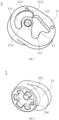
- FIG. 5 shows a schematic structural diagram of a portion of a cam 2 according to some embodiments of the present disclosure, in which the second rotating shaft 22 is not shown.
- the cam 2 includes a main portion 21 and a second rotating shaft 22.
- the main portion 21 is provided with a rotating hole 213 thereon, and the main portion 21 is disposed on the second rotating shaft 22 through the rotating hole 213.
- the main portion 21 is capable of rotating around the second rotating shaft 22.
- a side of the main portion 21 facing the operating mechanism 1 is provided with an arc groove 211 and an actuating groove 212.
- a part of the actuating shaft 13 is disposed within the actuating groove 212, and the third rotating shaft 14 is not in contact with the cam 2. Since the actuating shaft 13 is capable of rotating together with the operating handle, in a case that the operating handle is rotated, the actuating shaft 13 is capable of moving within the actuating groove 212 and contacts a groove wall of the actuating groove 212 to push the main portion 21 to rotate around the second rotating shaft 22.
- a part of the first rotating shaft 11 is disposed within the arc groove 211.
- the actuating shaft 13 pushes the main portion 21 to rotate around the second rotating shaft 22, different portions of a groove wall of the arc groove 211 contact the first rotating shaft 11.
- the first rotating shaft 11 since the first rotating shaft 11 is fixed on the mounting part 3, the first rotating shaft 11 cannot move.
- the main portion 21 is capable of rotating around the second rotating shaft 22, the first rotating shaft 11 is capable of contacting different portions of the groove wall of the arc groove 211.
- the arc groove 211 includes a first end 2111, a second end 2112, and an identification position 2113 located between the first end 2111 and the second end 2112.
- the actuating shaft 13 is capable of moving along the arc hole 31. A part of the actuating shaft 13 moves within the actuating groove 212 and contacts the groove wall of the actuating groove 212 to push the main portion 21 to rotate around the second rotating shaft 22, such that the first rotating shaft 11 switches from being adjacent to the first end 2111 to being adjacent to the identification position 2113, and the DC isolating switch 10 switches from the closed state to the opened state.
- FIG. 6 shows a schematic structural diagram of the cam as shown in FIG. 5 along another viewpoint.
- a side of the cam 2 away from the operating mechanism 1 is provided with a driving groove 214 mating with the driving part 6.
- the driving part 6 is provided within the driving groove 214.
- the moving contact 5 is connected to the driving part 6 and is provided in correspondence with the stationary contact 4.
- the moving contact 5 and the driving part 6 are capable of moving together with the cam 2.
- the DC isolating switch 10 is in the closed state.
- FIG. 3 in a case that the cam 2 drives the moving contact 5 to move and separates the moving contact 5 from the stationary contact 4, the DC isolating switch 10 is in the opened state.
- the main portion 21 can drive the driving part 6 to move together.
- the driving part 6 drives the moving contact 5 to move towards or away from the stationary contact 4 to realize switching of the DC isolating switch 10 between the opened state and the closed state.
- the moving contact 5 is connected to the stationary contact 4 and the DC isolating switch 10 is in the closed state.
- the actuating shaft 13 in a case that the operating handle is rotated, the actuating shaft 13 is capable of moving synchronously.
- the actuating shaft 13 moves within the actuating groove 212 and contacts the groove wall of the actuating groove 212 to push the main portion 21 to rotate around the second rotating shaft 22.
- the first rotating shaft11 switches from being adjacent to the first end 2111 to being adjacent to the identification position 2113, and the main portion 21 drives the moving contact 5 to move away from the stationary contact 4.
- the moving contact 5 is separated from the stationary contact 4 and the DC isolating switch 10 is in the opened state.
- an outer side wall of the driving part 6 is provided with a first limiting part 61.
- the first limiting part 61 is provided in correspondence with the second limiting part 7 and there is a spacing between the first limiting part 61 and the second limiting part 7. The spacing facilitates elongating an arc column of the arc to make the arc voltage larger, thereby facilitating the extinguishing of the arc.
- the first limiting part 61 moves toward the second limiting part 7.
- the first limiting part 61 contacts and hits the second limiting part 7.
- the cam 2 is capable of continuing to move due to the inertia to cause the first limiting part 61 to hits the second limiting part 7, and causing the first rotating shaft 11 to switch from being adjacent to the identification position 2113 to being adjacent to the second end 2112.
- the elasticity of the elastic part 12 is generally set to be large due to the need for quick extinguishing of the arc. Therefore, the force released by the elastic part 12 enables the first limiting part 61 to quickly hit the second limiting part 7.
- a rapid hitting of the first limiting part 61 on the second limiting part 7 is easy to lead to a phenomenon that the cam 2 is subjected to an uneven force and is deflected, which in turn leads to the second rotating shaft 22 of the cam 2 being subjected to a force and breaking.
- a part of the first rotating shaft 11 is provided within the arc groove 211. In a case that the main portion 21 rotates around the second rotating shaft 22, different portions of the groove wall of the arc groove 211 contact the first rotating shaft 11.
- the first rotating shaft 11 since the first rotating shaft 11 is always in contact with the groove wall of the arc groove 211, in a case that the first limiting part 61 quickly hits the second limiting part 7, the first rotating shaft 11 shares a part of the counter-impact force on the cam 2 and reduces the counter-impact force on the second rotating shaft 22, thereby effectively preventing the second rotating shaft 22 from breaking and increasing the service life of the DC isolating switch 10.
- the actuating groove 212 is provided with a protrusion 23.
- the protrusion 23 moves toward the actuating shaft 13, and in a case that the first rotating shaft 61 is adjacent to the second end 2112, the actuating shaft 13 contacts the protrusion 23.
- the force exerted by the actuating shaft 13 on the protrusion 23 is also capable of preventing the main portion 21 from continuing to rotate, thereby reducing the force of the first limiting part 61 hitting the second limiting part 7, which in turn allows the first limiting part 61 and/or second limiting part 7 are less likely to be damaged, which is benefit for increasing the service life of the DC isolating switch 10. It is to be understood that, as shown in FIG.
- the force exerted by the actuating shaft 13 on the protrusion 23 causes the main portion 21 to have a tendency to rotate clockwise, thereby causing the first limiting part 61 to have a tendency to move away from the second limiting part 7, which is benefit for reducing the force exerted by the first limiting part 61 hitting the second limiting part 7.
- the actuating shaft 13 in a case that the actuating shaft 13 contacts the groove wall of the actuating groove 212, the actuating shaft 13, the first rotating shaft 11, and the second rotating shaft 22 are all capable of contacting the main portion 21.
- the parts of the actuating shaft 13, the first rotating shaft 11, and the second rotating shaft 22 in contact with the main portion 21 form a triangle.
- a three-axis positioning helps to ensure the stability of the cam 2 during movement, and prevents the cam 2 from shifting, so that the second rotating shaft 22 will not be subjected to a force, thereby preventing the second rotating shaft 22 from breaking, and increasing the service life of the DC isolating switch 10.
- the cam 2 of the embodiments according to the present disclosure can be applied to various DC isolating switches 10 so as to the problem that the second rotating shaft is prone to fracture due to the need of quickly extinguishing the arc. It should be understood that the cam according to the embodiments of the present disclosure may also be applied to other components, and the embodiments of the present disclosure are not limited in this regard.
Landscapes
- Rotary Switch, Piano Key Switch, And Lever Switch (AREA)
- Driving Mechanisms And Operating Circuits Of Arc-Extinguishing High-Tension Switches (AREA)
Abstract
Embodiments of the present disclosure provide a DC isolating switch comprising an operating mechanism, the operating mechanism comprising an operating handle and a first rotating shaft, the operating handle being disposed on the first rotating shaft and rotating around the first rotating shaft; and a cam comprising a main portion and a second rotating shaft, the main portion being disposed on the second rotating shaft and capable of rotating around the second rotating shaft, wherein a side of the main portion facing the operating mechanism is provided with an arc groove, a part of the first rotating shaft is disposed within the arc groove, and in a case that the main portion rotates around the second rotating shaft, different portions of a groove wall of the arc groove contact the first rotating shaft.
Description
- Embodiments of the present disclosure generally relates to the field of electrical devices, and more specifically, to a DC isolating switch.
- There is a high demand for a DC isolating switch having a small volume and a high voltage. When the DC isolating switch switches from a closed state to an opened state, an arc may be generated in a gap between contacts. A conventional DC isolating switch drives a moving contact and a stationary contact to separate from each other through an energy released by an elastic part, such that the arc is transferred and extinguished. Therefore, in order to meet a requirement of quickly extinguishing the arc, an elasticity of the elastic part is generally set to be large. However, the large elasticity will drive a cam to hit a main body mechanism with a large impact force, and a counter-impact force of the main body mechanism on the cam also leads to a phenomenon of deflection of the cam due to an uneven force, which will lead to easy fracture of a cam shaft and affect a service life of the DC isolating switch.
- An object of the present disclosure is to provide a DC isolating switch to at least partially solve the above problem.
- The present disclosure provides a DC isolating switch comprising an operating mechanism, the operating mechanism comprising an operating handle and a first rotating shaft, the operating handle being disposed on the first rotating shaft and rotating around the first rotating shaft; and a cam comprising a main portion and a second rotating shaft, the main portion being disposed on the second rotating shaft and capable of rotating around the second rotating shaft, wherein a side of the main portion facing the operating mechanism is provided with an arc groove, a part of the first rotating shaft is disposed within the arc groove, and in a case that the main portion rotates around the second rotating shaft, different portions of a groove wall of the arc groove contact the first rotating shaft.
- For the DC isolating switch, in case of needing to quickly extinguish the arc, the main body mechanism may generate a counter-impact force on the cam, which may lead to a phenomenon of deflection of the cam due to an uneven force. In embodiments according to the present disclosure, since in a case that the main portion rotates around the second rotating shaft, different portions of the groove wall of the arc groove contact the first rotating shaft, the first rotating shaft shares a part of the counter-impact force to which the cam is subjected, reducing the counter-impact force borne by the second rotating shaft, thereby preventing the second rotating shaft from breaking and increasing the service life of the DC isolating switch. Thus, the DC isolating switch according to the present disclosure is capable of solving the problem that the second rotating shaft is prone to fracture due to the need of quickly extinguishing the arc.
- In some embodiments, the operating mechanism further comprises an actuating shaft disposed on the operating handle and capable of rotating together with the operating handle, a side of the main portion facing the operating mechanism is further provided with an actuating groove, the actuating shaft is capable of moving within the actuating groove and contacts the groove wall of the actuating groove to push the main portion to rotate around the second rotating shaft.
- In some embodiments, the arc groove comprises a first end, a second end and an identification position located between the first end and the second end, wherein in a case that the main portion rotates around the second rotating shaft to switch the first rotating shaft from being adjacent to the first end to being adjacent to the identification position, the DC isolating switch switches from a closed state to an opened state.
- In some embodiments, the DC isolating switch further comprises a moving contact and a driving part connected to the moving contact, a side of the cam away from the operating mechanism is provided with a driving groove mating with the driving part, and the driving part is disposed within the driving groove.
- In some embodiments, an outer side wall of the driving part is provided with a first limiting part, the DC isolating switch further comprises a second limiting part, wherein in a case that the first rotating shaft is adjacent to the identification position, a gap exists between the first limiting part and the second limiting part, during a process of the first rotating shaft switching from being adjacent to the identification position to being adjacent to the second end, the first limiting part moves toward the second limiting part, and in a case that the first rotating shaft is adjacent to the second end, the first limiting part contacts the second limiting part.
- In some embodiments, the actuating groove is provided with a protrusion, wherein during a process of the main portion rotating around the second rotating shaft to switch the first rotating shaft from being adjacent to the identification position to being adjacent to the second end, the protrusion moves toward the actuating shaft, and in a case that the first rotating shaft is adjacent to the second end, the actuating shaft contacts the protrusion.
- In some embodiments, the DC isolating switch further comprises a mounting part provided with a pair of arc holes thereon, the actuating shaft passes through one arc hole of the pair of arc holes, in a case that the operating handle is rotated, the actuating shaft is capable of moving along the corresponding arc hole.
- In some embodiments, the operating mechanism further comprises a third rotating shaft and a pair of elastic parts, one end of one elastic part of the pair of elastic parts is connected to the mounting part, and the other end is connected to the actuating shaft, one end of the other elastic part of the pair of elastic parts is connected to the mounting part, and the other end is connected to the third rotating shaft, the third rotating shaft passes through the other arc hole of the pair of arc holes, and in a case that the operating handle is rotated, the third rotating shaft is capable of moving along the corresponding arc hole.
- It should be understood that what is described in this section is not intended to limit the key features or important features of the embodiments of the present disclosure, nor is it intended to limit the scope of the present disclosure. Other features of the present disclosure will be readily understood by the following description.
- The above and other features, advantages and aspects of the various embodiments of the present disclosure will become more apparent in conjunction with the accompanying drawings and with reference to the following detailed description. In the drawings, like or similar reference numerals denote like or similar elements, in which:
-
FIG. 1 shows a schematic structural diagram of a portion of a DC isolating switch according to some embodiments of the present disclosure, in which the operating handle is not shown; -
FIG. 2 shows a schematic structural diagram of a portion of a DC isolating switch according to some embodiments of the present disclosure, in which the DC isolating switch is in a closed state, and the operating handle, the elastic part, and the mounting part are not shown; -
FIG. 3 shows a schematic structural diagram of a portion of the DC isolating switch as shown inFIG. 2 , in which the DC isolating switch is in an opened state; -
FIG. 4 shows a schematic structural diagram of a portion of the DC isolating switch as shown inFIG. 2 , in which the first rotating shaft is adjacent to the second end; -
FIG. 5 shows a schematic structural diagram of a portion of a cam according to some embodiments of the present disclosure, in which the second rotating shaft is not shown; -
FIG. 6 shows a schematic structural diagram of the cam as shown inFIG. 5 along another viewpoint. - List of reference symbols:
- 10 represents a DC isolating switch;
- 1 represents an operating mechanism, 11 represents a first rotating shaft, 12 represents an elastic part, 13 represents an actuating shaft, and 14 represents a third rotating shaft;
- 2 represents a cam, 21 represents a main portion, 211 represents an arc groove, 2111 represents a first end, 2112 represents a second end, 2113 represents an identification position, 212 represents an actuating groove, 213 represents a rotating hole, 214 represents a driving groove, 22 represents a second rotating shaft, and 23 represents a protrusion;
- 3 represents a mounting part, 31 represents an arc hole;
- 4 represents a stationary contact; 5 represents a moving contact; 6 represents a driving part, 61 represents a first limiting part; 7 represents a second limiting part.
- Preferred embodiments of the present disclosure will be described in greater detail below with reference to the accompanying drawings. Although preferred embodiments of the present disclosure are shown in the accompanying drawings, it should be understood, however, that the present disclosure may be realized in various forms without being limited by the embodiments set forth herein. Rather, these embodiments are provided to make the present disclosure more thorough and complete and to enable the scope of the present disclosure to be communicated in its entirety to those skilled in the art.
- The term "including" and variations thereof denote open-ended inclusion, i.e., "including but not limited to." Unless specifically stated, the term "or" denotes "and/or". The term "based on" means "at least partially based on". The terms "an example embodiment" and "an embodiment" denote "at least one example embodiment". The term "another embodiment" denotes "at least one additional embodiment". The terms "first", "second", etc. may refer to different or identical objects.
- As described above, a counter-impact force of a main body mechanism on a cam leads to a phenomenon of deflection of the cam due to an uneven force, which will lead to easy fracture of a cam shaft and affect a service life of a DC isolating switch. The embodiments of the present disclosure provide a DC isolating switch to solve a problem that a second rotating shaft is prone to fracture due to the need of quickly extinguishing an arc. In the following, the principles of the present disclosure will be described in conjunction with
FIGS. 1 to 6 . -
FIG. 1 shows a schematic structural diagram of a portion of aDC isolating switch 10 according to some embodiments of the present disclosure, in which the operating handle is not shown.FIG. 2 shows a schematic structural diagram of a portion of aDC isolating switch 10 according to some embodiments of the present disclosure, in which theDC isolating switch 10 is in a closed state, and the operating handle, theelastic part 12, and themounting part 3 are not shown. As shown inFIGS. 1 to 2 , theDC isolating switch 10 described herein generally includes an operating mechanism 1, acam 2, amounting part 3, astationary contact 4, a movingcontact 5, a drivingpart 6, and a second limitingpart 7. - As shown in
FIG. 1 , themounting part 3 serves as a mounting carrier, which is used to set the operating mechanism 1. Themounting part 3 is provided with a pair ofarc holes 31 thereon. The operating mechanism 1 includes an operating handle (not shown in the figure), a firstrotating shaft 11, a pair ofelastic parts 12, anactuating shaft 13, and a third rotatingshaft 14. - Continuing as shown in
FIG. 1 , the first rotatingshaft 11 is disposed on themounting part 3, and the first rotatingshaft 11 is limited by themounting part 3. The operating handle is disposed on the first rotatingshaft 11. Upon being driven, the operating handle is capable of rotating around the first rotatingshaft 11 relative to themounting part 3. - Continuing as shown in
FIG. 1 , in some embodiments, one end of oneelastic part 12 of the pair ofelastic parts 12 is connected to themounting part 3, and the other end is connected to the actuatingshaft 13. One end of the otherelastic part 12 of the pair ofelastic parts 12 is connected to themounting part 3, and the other end is connected to the third rotatingshaft 14. The actuatingshaft 13 passes through one arc hole of the pair ofarc holes 31. The third rotatingshaft 14 passes through the other arc hole of the pair ofarc holes 31. Both the actuatingshaft 13 and the third rotatingshaft 14 are disposed on the operating handle. Therefore, during a process of the operating handle rotating around the firstrotating shaft 11, the actuatingshaft 13 and the thirdrotating shaft 14 are capable of moving along thecorresponding arc hole 31, simultaneously. It should be noted that the actuatingshaft 13 and the thirdrotating shaft 14 have opposite paths of movement within the correspondingarc hole 31. That is, as shown inFIG. 1 , in a case that the actuatingshaft 13 rotates counterclockwise along thecorresponding arc hole 31, the thirdrotating shaft 14 rotates clockwise within the correspondingarc hole 31. In a case that the actuatingshaft 13 rotates clockwise along thecorresponding arc hole 31, the thirdrotating shaft 14 rotates counterclockwise within the correspondingarc hole 31. - Utilizing the above configuration, as shown in
FIG. 1 , in a case that the operating handle is rotated, the actuatingshaft 13 and the thirdrotating shaft 14 are capable of moving along thecorresponding arc hole 31, respectively, and the paths of movement of the actuatingshaft 13 and the thirdrotating shaft 14 are opposite. Then, in a case that the operating handle moves to a certain position, the actuatingshaft 13 and the thirdrotating shaft 14 are capable of driving the correspondingelastic part 12 to a dead point position, that is, a straight line is formed approximately between the pair ofelastic parts 12. The pair ofelastic parts 12 are unstable at the dead point position, and the pair ofelastic parts 12 are compressed by the force. Theelastic part 12 in a compressed state is capable of releasing energy and driving theactuating shaft 13 and the thirdrotating shaft 14 to continue to move within the corresponding arc holes 31, thereby driving the operating handle to switch theDC isolating switch 10 between the closed state and the opened state. In a case that the pair ofelastic parts 12 are in the dead point position, the movingcontact 5 and thestationary contact 4 are in a critical state between a separated state and a connected state. That is, the movingcontact 5 andstationary contact 4 are about to separate or about to connect. - It can be understood that during a process of the pair of
elastic parts 12 switching from other positions to the dead point position, the operator needs to turn the operating handle to drive theelastic part 12 to move. In a case that the pair ofelastic parts 12 are switched to the dead point position, theelastic part 12 is compressed to store energy. Theelastic part 12 in the compressed state is capable of releasing energy and driving theactuating shaft 13 and the thirdrotating shaft 14 to move, thereby driving the operating handle to move without the need for the operator to apply force to rotate the operating handle. - An exemplary structure of the
DC isolating switch 10 is further described below in connection withFIGS. 3 to 4 .FIG. 3 shows a schematic structural diagram of a portion of theDC isolating switch 10 as shown inFIG. 2 , in which theDC isolating switch 10 is in an opened state.FIG. 4 shows a schematic structural diagram of a portion of theDC isolating switch 10 as shown inFIG. 2 , in which the firstrotating shaft 11 is adjacent to thesecond end 2112.FIG. 5 shows a schematic structural diagram of a portion of acam 2 according to some embodiments of the present disclosure, in which the secondrotating shaft 22 is not shown. As shown in conjunction withFIGS. 2 to 5 , thecam 2 includes amain portion 21 and a secondrotating shaft 22. Themain portion 21 is provided with arotating hole 213 thereon, and themain portion 21 is disposed on the secondrotating shaft 22 through therotating hole 213. Themain portion 21 is capable of rotating around the secondrotating shaft 22. A side of themain portion 21 facing the operating mechanism 1 is provided with anarc groove 211 and anactuating groove 212. A part of the actuatingshaft 13 is disposed within theactuating groove 212, and the thirdrotating shaft 14 is not in contact with thecam 2. Since the actuatingshaft 13 is capable of rotating together with the operating handle, in a case that the operating handle is rotated, the actuatingshaft 13 is capable of moving within theactuating groove 212 and contacts a groove wall of theactuating groove 212 to push themain portion 21 to rotate around the secondrotating shaft 22. A part of the firstrotating shaft 11 is disposed within thearc groove 211. In a case that the actuatingshaft 13 pushes themain portion 21 to rotate around the secondrotating shaft 22, different portions of a groove wall of thearc groove 211 contact the firstrotating shaft 11. It will be appreciated that since the firstrotating shaft 11 is fixed on the mountingpart 3, the firstrotating shaft 11 cannot move. However, since themain portion 21 is capable of rotating around the secondrotating shaft 22, the firstrotating shaft 11 is capable of contacting different portions of the groove wall of thearc groove 211. - It is noted that there is a spacing between a part of the first
rotating shaft 11 located within thearc groove 211 and the bottom of the groove of thearc groove 211. There is also a spacing between a part of the actuatingshaft 13 located within theactuating groove 212 and the bottom of the groove of theactuating groove 212. - Continuing as shown in
FIGS. 2 to 5 , in some embodiments, thearc groove 211 includes afirst end 2111, asecond end 2112, and anidentification position 2113 located between thefirst end 2111 and thesecond end 2112. In a case that the operating handle is rotated, the actuatingshaft 13 is capable of moving along thearc hole 31. A part of the actuatingshaft 13 moves within theactuating groove 212 and contacts the groove wall of theactuating groove 212 to push themain portion 21 to rotate around the secondrotating shaft 22, such that the firstrotating shaft 11 switches from being adjacent to thefirst end 2111 to being adjacent to theidentification position 2113, and theDC isolating switch 10 switches from the closed state to the opened state. - An exemplary structure of the
cam 2 is described further below in connection withFIG. 6. FIG. 6 shows a schematic structural diagram of the cam as shown inFIG. 5 along another viewpoint. As shown inFIGS. 2 to 4 andFIG. 6 , a side of thecam 2 away from the operating mechanism 1 is provided with a drivinggroove 214 mating with the drivingpart 6. The drivingpart 6 is provided within the drivinggroove 214. The movingcontact 5 is connected to the drivingpart 6 and is provided in correspondence with thestationary contact 4. By utilizing the above configuration, the movingcontact 5 and the drivingpart 6 are capable of moving together with thecam 2. As shown inFIG. 2 , in a case that thecam 2 drives the movingcontact 5 to move and connects the movingcontact 5 to thestationary contact 4, theDC isolating switch 10 is in the closed state. As shown inFIG. 3 , in a case that thecam 2 drives the movingcontact 5 to move and separates the movingcontact 5 from thestationary contact 4, theDC isolating switch 10 is in the opened state. - With the above configuration, in a case that the
main portion 21 rotates around the secondrotating shaft 22, themain portion 21 can drive the drivingpart 6 to move together. The drivingpart 6 drives the movingcontact 5 to move towards or away from thestationary contact 4 to realize switching of theDC isolating switch 10 between the opened state and the closed state. - Returning to
FIG. 2 , in a case that the firstrotating shaft 11 is adjacent to thefirst end 2111, the movingcontact 5 is connected to thestationary contact 4 and theDC isolating switch 10 is in the closed state. Returning toFIG. 3 , in a case that the operating handle is rotated, the actuatingshaft 13 is capable of moving synchronously. The actuatingshaft 13 moves within theactuating groove 212 and contacts the groove wall of theactuating groove 212 to push themain portion 21 to rotate around the secondrotating shaft 22. During a process of the movement, the first rotating shaft11 switches from being adjacent to thefirst end 2111 to being adjacent to theidentification position 2113, and themain portion 21 drives the movingcontact 5 to move away from thestationary contact 4. In a case that the firstrotating shaft 11 is adjacent to theidentification position 2113, the movingcontact 5 is separated from thestationary contact 4 and theDC isolating switch 10 is in the opened state. - Continuing back to
FIG. 4 , an outer side wall of the drivingpart 6 is provided with a first limitingpart 61. In a case that the firstrotating shaft 11 is adjacent to theidentification position 2113, the first limitingpart 61 is provided in correspondence with the second limitingpart 7 and there is a spacing between the first limitingpart 61 and the second limitingpart 7. The spacing facilitates elongating an arc column of the arc to make the arc voltage larger, thereby facilitating the extinguishing of the arc. During a process of the firstrotating shaft 11 switching from being adjacent to theidentification position 2113 to being adjacent to thesecond end 2112, the first limitingpart 61 moves toward the second limitingpart 7. In a case that the firstrotating shaft 11 is adjacent to thesecond end 2112, the first limitingpart 61 contacts and hits the second limitingpart 7. - It should be noted that in a case that the actuating
shaft 13 moves along thecorresponding arc hole 31 and causes theactuating shaft 13 to move to an end of thearc hole 31, although the actuatingshaft 13 is limited by the end of thearc hole 31 and cannot continue to move, thecam 2 is capable of continuing to move due to the inertia to cause the first limitingpart 61 to hits the second limitingpart 7, and causing the firstrotating shaft 11 to switch from being adjacent to theidentification position 2113 to being adjacent to thesecond end 2112. The elasticity of theelastic part 12 is generally set to be large due to the need for quick extinguishing of the arc. Therefore, the force released by theelastic part 12 enables the first limitingpart 61 to quickly hit the second limitingpart 7. - On the one hand, a rapid hitting of the first limiting
part 61 on the second limitingpart 7 is easy to lead to a phenomenon that thecam 2 is subjected to an uneven force and is deflected, which in turn leads to the secondrotating shaft 22 of thecam 2 being subjected to a force and breaking. To solve the above problem, as shown inFIGS. 2 to 4 , in some embodiments, a part of the firstrotating shaft 11 is provided within thearc groove 211. In a case that themain portion 21 rotates around the secondrotating shaft 22, different portions of the groove wall of thearc groove 211 contact the firstrotating shaft 11. Utilizing the above configuration, since the firstrotating shaft 11 is always in contact with the groove wall of thearc groove 211, in a case that the first limitingpart 61 quickly hits the second limitingpart 7, the firstrotating shaft 11 shares a part of the counter-impact force on thecam 2 and reduces the counter-impact force on the secondrotating shaft 22, thereby effectively preventing the secondrotating shaft 22 from breaking and increasing the service life of theDC isolating switch 10. - On the other hand, the rapid hitting of the first limiting
part 61 on the second limitingpart 7 is also easy to lead damage to the first limitingpart 61 and/or the second limitingpart 7. To solve the above problems, as shown inFIGS. 2 to 4 , in some embodiments, theactuating groove 212 is provided with aprotrusion 23. During a process of themain portion 21 continuing to rotate around the secondrotating shaft 22 due to inertia and causing the firstrotating shaft 11 to switch from being adjacent to theidentification position 2113 to being adjacent to thesecond end 2112, theprotrusion 23 moves toward the actuatingshaft 13, and in a case that the firstrotating shaft 61 is adjacent to thesecond end 2112, the actuatingshaft 13 contacts theprotrusion 23. Utilizing the above configuration, the force exerted by the actuatingshaft 13 on theprotrusion 23 is also capable of preventing themain portion 21 from continuing to rotate, thereby reducing the force of the first limitingpart 61 hitting the second limitingpart 7, which in turn allows the first limitingpart 61 and/or second limitingpart 7 are less likely to be damaged, which is benefit for increasing the service life of theDC isolating switch 10. It is to be understood that, as shown inFIG. 4 , the force exerted by the actuatingshaft 13 on theprotrusion 23 causes themain portion 21 to have a tendency to rotate clockwise, thereby causing the first limitingpart 61 to have a tendency to move away from the second limitingpart 7, which is benefit for reducing the force exerted by the first limitingpart 61 hitting the second limitingpart 7. - As shown in
FIGS. 3 to 4 , in some embodiments, in a case that the actuatingshaft 13 contacts the groove wall of theactuating groove 212, the actuatingshaft 13, the firstrotating shaft 11, and the secondrotating shaft 22 are all capable of contacting themain portion 21. With the above configuration, the parts of the actuatingshaft 13, the firstrotating shaft 11, and the secondrotating shaft 22 in contact with themain portion 21 form a triangle. In other words, a three-axis positioning helps to ensure the stability of thecam 2 during movement, and prevents thecam 2 from shifting, so that the secondrotating shaft 22 will not be subjected to a force, thereby preventing the secondrotating shaft 22 from breaking, and increasing the service life of theDC isolating switch 10. - The
cam 2 of the embodiments according to the present disclosure can be applied to variousDC isolating switches 10 so as to the problem that the second rotating shaft is prone to fracture due to the need of quickly extinguishing the arc. It should be understood that the cam according to the embodiments of the present disclosure may also be applied to other components, and the embodiments of the present disclosure are not limited in this regard. - Various embodiments of the present disclosure have been described above, and the foregoing description is exemplary and not exhaustive, and is not limited to the various embodiments disclosed. Without departing from the scope and spirit of the various embodiments described, many modifications and changes will be apparent to one of ordinary skill in this field. The terminology used herein has been chosen to best explain the principles, practical applications, or improvements to the technology in the marketplace of the respective embodiments, or to enable others of ordinary skill in this field to understand the respective embodiments disclosed herein.
Claims (8)
- A DC isolating switch (10), characterized by comprising:an operating mechanism (1) comprising an operating handle and a first rotating shaft (11), the operating handle being disposed on the first rotating shaft (11) and rotating around the first rotating shaft (11); anda cam (2) comprising a main portion (21) and a second rotating shaft (22), the main portion (21) being disposed on the second rotating shaft (22) and capable of rotating around the second rotating shaft (22), wherein a side of the main portion (21) facing the operating mechanism (1) is provided with an arc groove (211), a part of the first rotating shaft (11) is disposed within the arc groove (211), and in a case that the main portion (21) rotates around the second rotating shaft (22), different portions of a groove wall of the arc groove (211) contact the first rotating shaft (11).
- The DC isolating switch (10) of claim 1, characterized in that the operating mechanism (1) further comprises an actuating shaft (13) disposed on the operating handle and capable of rotating together with the operating handle, a side of the main portion (21) facing the operating mechanism (1) is further provided with an actuating groove (212), the actuating shaft (13) is capable of moving within the actuating groove (212) and contacts the groove wall of the actuating groove (212) to push the main portion (21) to rotate around the second rotating shaft (22).
- The DC isolating switch (10) of claim 2, characterized in that the arc groove (211) comprises a first end (2111), a second end (2112) and an identification position (2113) located between the first end (2111) and the second end (2112), wherein in a case that the main portion (21) rotates around the second rotating shaft (22) to switch the first rotating shaft (11) from being adjacent to the first end (2111) to being adjacent to the identification position (2113), the DC isolating switch (10) switches from a closed state to an opened state.
- The DC isolating switch (10) of claim 3, characterized in that the DC isolating switch (10) further comprises a moving contact (5) and a driving part (6) connected to the moving contact (5), a side of the cam (2) away from the operating mechanism (1) is provided with a driving groove (214) mating with the driving part (6), and the driving part (6) is disposed within the driving groove (214).
- The DC isolating switch (10) of claim 4, characterized in that an outer side wall of the driving part (6) is provided with a first limiting part (61), the DC isolating switch (10) further comprises a second limiting part (7), wherein in a case that the first rotating shaft (11) is adjacent to the identification position (2113), a gap exists between the first limiting part (61) and the second limiting part (7), during a process of the first rotating shaft (11) switching from being adjacent to the identification position (2113) to being adjacent to the second end (2112), the first limiting part (61) moves toward the second limiting part (7), and in a case that the first rotating shaft (11) is adjacent to the second end (2112), the first limiting part (61) contacts the second limiting part (7).
- The DC isolating switch (10) of claims 5, characterized in that the actuating groove (212) is provided with a protrusion (23), wherein during a process of the main portion (21) rotating around the second rotating shaft (22) to switch the first rotating shaft (11) from being adjacent to the identification position (2113) to being adjacent to the second end (2112), the protrusion (23) moves toward the actuating shaft (13), and in a case that the first rotating shaft (11) is adjacent to the second end (2112), the actuating shaft (13) contacts the protrusion (23).
- The DC isolating switch (10) of claim 2, characterized in that the DC isolating switch (10) further comprises a mounting part (3) provided with a pair of arc holes (31) thereon, the actuating shaft (13) passes through one arc hole (31) of the pair of arc holes (31), in a case that the operating handle is rotated, the actuating shaft (13) is capable of moving along the corresponding arc hole (31).
- The DC isolating switch (10) of claim 7, characterized in that the operating mechanism (1) further comprises a third rotating shaft (14) and a pair of elastic parts (12), one end of one elastic part (12) of the pair of elastic parts (12) is connected to the mounting part (3), and the other end is connected to the actuating shaft (13), one end of the other elastic part (12) of the pair of elastic parts (12) is connected to the mounting part (3), and the other end is connected to the third rotating shaft (14), the third rotating shaft (14) passes through the other arc hole of the pair of arc holes (31), and in a case that the operating handle is rotated, the third rotating shaft (14) is capable of moving along the corresponding arc hole (31).
Applications Claiming Priority (1)
| Application Number | Priority Date | Filing Date | Title |
|---|---|---|---|
| CN202321578648.8U CN220085913U (en) | 2023-06-19 | 2023-06-19 | DC isolating switch |
Publications (1)
| Publication Number | Publication Date |
|---|---|
| EP4481781A1 true EP4481781A1 (en) | 2024-12-25 |
Family
ID=88828442
Family Applications (1)
| Application Number | Title | Priority Date | Filing Date |
|---|---|---|---|
| EP24305952.4A Pending EP4481781A1 (en) | 2023-06-19 | 2024-06-17 | Dc isolating switch |
Country Status (2)
| Country | Link |
|---|---|
| EP (1) | EP4481781A1 (en) |
| CN (1) | CN220085913U (en) |
Citations (4)
| Publication number | Priority date | Publication date | Assignee | Title |
|---|---|---|---|---|
| CN104425147A (en) * | 2013-08-30 | 2015-03-18 | 西门子公司 | Disconnecting switch |
| CN107622883A (en) * | 2017-10-31 | 2018-01-23 | 浙江科瑞普电气有限公司 | A kind of direct-current isolating switch |
| CN218038969U (en) * | 2021-06-28 | 2022-12-13 | 北京光华世通科技有限公司 | An electrical isolating switch |
| US20230115069A1 (en) * | 2019-06-17 | 2023-04-13 | Zhejiang Benyi Electrical Co., Ltd. | Dual energy storage operating mechanism of isolating switch |
-
2023
- 2023-06-19 CN CN202321578648.8U patent/CN220085913U/en active Active
-
2024
- 2024-06-17 EP EP24305952.4A patent/EP4481781A1/en active Pending
Patent Citations (4)
| Publication number | Priority date | Publication date | Assignee | Title |
|---|---|---|---|---|
| CN104425147A (en) * | 2013-08-30 | 2015-03-18 | 西门子公司 | Disconnecting switch |
| CN107622883A (en) * | 2017-10-31 | 2018-01-23 | 浙江科瑞普电气有限公司 | A kind of direct-current isolating switch |
| US20230115069A1 (en) * | 2019-06-17 | 2023-04-13 | Zhejiang Benyi Electrical Co., Ltd. | Dual energy storage operating mechanism of isolating switch |
| CN218038969U (en) * | 2021-06-28 | 2022-12-13 | 北京光华世通科技有限公司 | An electrical isolating switch |
Also Published As
| Publication number | Publication date |
|---|---|
| CN220085913U (en) | 2023-11-24 |
Similar Documents
| Publication | Publication Date | Title |
|---|---|---|
| CN111128618B (en) | Operating mechanism of low-voltage molded case circuit breaker | |
| EP3975218B1 (en) | A load break switch | |
| US11145472B2 (en) | Electrical contact system | |
| CN218826826U (en) | Connecting rod transmission mechanism | |
| EP3933868A1 (en) | Operation mechanism for dual-power automatic transfer switch and dual-power automatic transfer switch | |
| EP4293695A1 (en) | Direct driven latch for ultra-fast switch | |
| CN220085913U (en) | DC isolating switch | |
| JP2024537949A (en) | Switchgear operating mechanism and switchgear | |
| CN222775211U (en) | Interlocking structure of disconnector operating mechanism and circuit breaker operating mechanism and circuit breaker | |
| US20260018360A1 (en) | Operating mechanism | |
| JPH04267020A (en) | Electric switch contact device having quick- break arc contact point | |
| KR20070008041A (en) | Gas insulated circuit breaker | |
| CN107123565B (en) | gas circuit breaker | |
| US9269506B2 (en) | Movable contact arm for molded case circuit breaker and movable contact arm assembly | |
| WO2023188287A1 (en) | Opening and closing device | |
| CN212209399U (en) | Switching-off device and circuit breaker | |
| CN223911547U (en) | Dual power transfer switch | |
| US20180197694A1 (en) | Indication device of electric switch | |
| JP3294464B2 (en) | Circuit breaker operating device and vacuum circuit breaker | |
| JPH10241515A (en) | Operation mechanism of auxiliary switch | |
| US20250087436A1 (en) | Solid-state circuit breaker | |
| CN214900324U (en) | Dual-power automatic transfer switch | |
| CN207558720U (en) | A miniature circuit breaker and circuit protection device | |
| CN220984365U (en) | Automatic transfer switch electric appliance and contact system thereof | |
| JP4149537B2 (en) | Compressed air driven air switch |
Legal Events
| Date | Code | Title | Description |
|---|---|---|---|
| PUAI | Public reference made under article 153(3) epc to a published international application that has entered the european phase |
Free format text: ORIGINAL CODE: 0009012 |
|
| STAA | Information on the status of an ep patent application or granted ep patent |
Free format text: STATUS: THE APPLICATION HAS BEEN PUBLISHED |
|
| AK | Designated contracting states |
Kind code of ref document: A1 Designated state(s): AL AT BE BG CH CY CZ DE DK EE ES FI FR GB GR HR HU IE IS IT LI LT LU LV MC ME MK MT NL NO PL PT RO RS SE SI SK SM TR |
|
| STAA | Information on the status of an ep patent application or granted ep patent |
Free format text: STATUS: REQUEST FOR EXAMINATION WAS MADE |
|
| 17P | Request for examination filed |
Effective date: 20250624 |