EP4481706A1 - Information providing apparatus, information providing method, and information providing program - Google Patents
Information providing apparatus, information providing method, and information providing program Download PDFInfo
- Publication number
- EP4481706A1 EP4481706A1 EP24181630.5A EP24181630A EP4481706A1 EP 4481706 A1 EP4481706 A1 EP 4481706A1 EP 24181630 A EP24181630 A EP 24181630A EP 4481706 A1 EP4481706 A1 EP 4481706A1
- Authority
- EP
- European Patent Office
- Prior art keywords
- image data
- pieces
- information providing
- condition
- measurement
- Prior art date
- Legal status (The legal status is an assumption and is not a legal conclusion. Google has not performed a legal analysis and makes no representation as to the accuracy of the status listed.)
- Pending
Links
Images




Classifications
-
- G—PHYSICS
- G01—MEASURING; TESTING
- G01D—MEASURING NOT SPECIALLY ADAPTED FOR A SPECIFIC VARIABLE; ARRANGEMENTS FOR MEASURING TWO OR MORE VARIABLES NOT COVERED IN A SINGLE OTHER SUBCLASS; TARIFF METERING APPARATUS; MEASURING OR TESTING NOT OTHERWISE PROVIDED FOR
- G01D21/00—Measuring or testing not otherwise provided for
- G01D21/02—Measuring two or more variables by means not covered by a single other subclass
-
- G—PHYSICS
- G08—SIGNALLING
- G08B—SIGNALLING SYSTEMS, e.g. PERSONAL CALLING SYSTEMS; ORDER TELEGRAPHS; ALARM SYSTEMS
- G08B13/00—Burglar, theft or intruder alarms
- G08B13/18—Actuation by interference with heat, light, or radiation of shorter wavelength; Actuation by intruding sources of heat, light, or radiation of shorter wavelength
- G08B13/189—Actuation by interference with heat, light, or radiation of shorter wavelength; Actuation by intruding sources of heat, light, or radiation of shorter wavelength using passive radiation detection systems
- G08B13/194—Actuation by interference with heat, light, or radiation of shorter wavelength; Actuation by intruding sources of heat, light, or radiation of shorter wavelength using passive radiation detection systems using image scanning and comparing systems
- G08B13/196—Actuation by interference with heat, light, or radiation of shorter wavelength; Actuation by intruding sources of heat, light, or radiation of shorter wavelength using passive radiation detection systems using image scanning and comparing systems using television cameras
- G08B13/19697—Arrangements wherein non-video detectors generate an alarm themselves
-
- G—PHYSICS
- G06—COMPUTING OR CALCULATING; COUNTING
- G06T—IMAGE DATA PROCESSING OR GENERATION, IN GENERAL
- G06T11/00—Two-dimensional [2D] image generation
- G06T11/60—Creating or editing images; Combining images with text
-
- G—PHYSICS
- G05—CONTROLLING; REGULATING
- G05B—CONTROL OR REGULATING SYSTEMS IN GENERAL; FUNCTIONAL ELEMENTS OF SUCH SYSTEMS; MONITORING OR TESTING ARRANGEMENTS FOR SUCH SYSTEMS OR ELEMENTS
- G05B19/00—Program-control systems
- G05B19/02—Program-control systems electric
- G05B19/04—Program control other than numerical control, i.e. in sequence controllers or logic controllers
- G05B19/042—Program control other than numerical control, i.e. in sequence controllers or logic controllers using digital processors
-
- G—PHYSICS
- G06—COMPUTING OR CALCULATING; COUNTING
- G06F—ELECTRIC DIGITAL DATA PROCESSING
- G06F3/00—Input arrangements for transferring data to be processed into a form capable of being handled by the computer; Output arrangements for transferring data from processing unit to output unit, e.g. interface arrangements
- G06F3/01—Input arrangements or combined input and output arrangements for interaction between user and computer
- G06F3/048—Interaction techniques based on graphical user interfaces [GUI]
- G06F3/0484—Interaction techniques based on graphical user interfaces [GUI] for the control of specific functions or operations, e.g. selecting or manipulating an object, an image or a displayed text element, setting a parameter value or selecting a range
- G06F3/04842—Selection of displayed objects or displayed text elements
-
- G—PHYSICS
- G06—COMPUTING OR CALCULATING; COUNTING
- G06F—ELECTRIC DIGITAL DATA PROCESSING
- G06F3/00—Input arrangements for transferring data to be processed into a form capable of being handled by the computer; Output arrangements for transferring data from processing unit to output unit, e.g. interface arrangements
- G06F3/01—Input arrangements or combined input and output arrangements for interaction between user and computer
- G06F3/048—Interaction techniques based on graphical user interfaces [GUI]
- G06F3/0484—Interaction techniques based on graphical user interfaces [GUI] for the control of specific functions or operations, e.g. selecting or manipulating an object, an image or a displayed text element, setting a parameter value or selecting a range
- G06F3/04845—Interaction techniques based on graphical user interfaces [GUI] for the control of specific functions or operations, e.g. selecting or manipulating an object, an image or a displayed text element, setting a parameter value or selecting a range for image manipulation, e.g. dragging, rotation, expansion or change of colour
-
- G—PHYSICS
- G06—COMPUTING OR CALCULATING; COUNTING
- G06F—ELECTRIC DIGITAL DATA PROCESSING
- G06F3/00—Input arrangements for transferring data to be processed into a form capable of being handled by the computer; Output arrangements for transferring data from processing unit to output unit, e.g. interface arrangements
- G06F3/01—Input arrangements or combined input and output arrangements for interaction between user and computer
- G06F3/048—Interaction techniques based on graphical user interfaces [GUI]
- G06F3/0484—Interaction techniques based on graphical user interfaces [GUI] for the control of specific functions or operations, e.g. selecting or manipulating an object, an image or a displayed text element, setting a parameter value or selecting a range
- G06F3/04847—Interaction techniques to control parameter settings, e.g. interaction with sliders or dials
-
- G—PHYSICS
- G06—COMPUTING OR CALCULATING; COUNTING
- G06F—ELECTRIC DIGITAL DATA PROCESSING
- G06F3/00—Input arrangements for transferring data to be processed into a form capable of being handled by the computer; Output arrangements for transferring data from processing unit to output unit, e.g. interface arrangements
- G06F3/14—Digital output to display device ; Cooperation and interconnection of the display device with other functional units
-
- G—PHYSICS
- G06—COMPUTING OR CALCULATING; COUNTING
- G06T—IMAGE DATA PROCESSING OR GENERATION, IN GENERAL
- G06T11/00—Two-dimensional [2D] image generation
- G06T11/20—Drawing from basic elements
- G06T11/26—Drawing of charts or graphs
-
- G—PHYSICS
- G11—INFORMATION STORAGE
- G11B—INFORMATION STORAGE BASED ON RELATIVE MOVEMENT BETWEEN RECORD CARRIER AND TRANSDUCER
- G11B27/00—Editing; Indexing; Addressing; Timing or synchronising; Monitoring; Measuring tape travel
- G11B27/02—Editing, e.g. varying the order of information signals recorded on, or reproduced from, record carriers
- G11B27/031—Electronic editing of digitised analogue information signals, e.g. audio or video signals
- G11B27/034—Electronic editing of digitised analogue information signals, e.g. audio or video signals on discs
-
- H—ELECTRICITY
- H04—ELECTRIC COMMUNICATION TECHNIQUE
- H04N—PICTORIAL COMMUNICATION, e.g. TELEVISION
- H04N5/00—Details of television systems
- H04N5/76—Television signal recording
- H04N5/765—Interface circuits between an apparatus for recording and another apparatus
- H04N5/77—Interface circuits between an apparatus for recording and another apparatus between a recording apparatus and a television camera
- H04N5/772—Interface circuits between an apparatus for recording and another apparatus between a recording apparatus and a television camera the recording apparatus and the television camera being placed in the same enclosure
-
- H—ELECTRICITY
- H04—ELECTRIC COMMUNICATION TECHNIQUE
- H04N—PICTORIAL COMMUNICATION, e.g. TELEVISION
- H04N9/00—Details of colour television systems
- H04N9/79—Processing of colour television signals in connection with recording
- H04N9/80—Transformation of the television signal for recording, e.g. modulation, frequency changing; Inverse transformation for playback
- H04N9/82—Transformation of the television signal for recording, e.g. modulation, frequency changing; Inverse transformation for playback the individual colour picture signal components being recorded simultaneously only
- H04N9/8205—Transformation of the television signal for recording, e.g. modulation, frequency changing; Inverse transformation for playback the individual colour picture signal components being recorded simultaneously only involving the multiplexing of an additional signal and the colour video signal
-
- G—PHYSICS
- G08—SIGNALLING
- G08B—SIGNALLING SYSTEMS, e.g. PERSONAL CALLING SYSTEMS; ORDER TELEGRAPHS; ALARM SYSTEMS
- G08B13/00—Burglar, theft or intruder alarms
- G08B13/18—Actuation by interference with heat, light, or radiation of shorter wavelength; Actuation by intruding sources of heat, light, or radiation of shorter wavelength
- G08B13/189—Actuation by interference with heat, light, or radiation of shorter wavelength; Actuation by intruding sources of heat, light, or radiation of shorter wavelength using passive radiation detection systems
- G08B13/194—Actuation by interference with heat, light, or radiation of shorter wavelength; Actuation by intruding sources of heat, light, or radiation of shorter wavelength using passive radiation detection systems using image scanning and comparing systems
- G08B13/196—Actuation by interference with heat, light, or radiation of shorter wavelength; Actuation by intruding sources of heat, light, or radiation of shorter wavelength using passive radiation detection systems using image scanning and comparing systems using television cameras
- G08B13/19695—Arrangements wherein non-video detectors start video recording or forwarding but do not generate an alarm themselves
-
- G—PHYSICS
- G08—SIGNALLING
- G08B—SIGNALLING SYSTEMS, e.g. PERSONAL CALLING SYSTEMS; ORDER TELEGRAPHS; ALARM SYSTEMS
- G08B21/00—Alarms responsive to a single specified undesired or abnormal condition and not otherwise provided for
- G08B21/18—Status alarms
- G08B21/182—Level alarms, e.g. alarms responsive to variables exceeding a threshold
Definitions
- the present invention relates to an information providing apparatus, an information providing method, and an information providing program.
- the present invention relates to an information providing apparatus, an information providing method, and an information providing program.
- a process of recording the measurement results and the images into the single file or the like is referred to as a merge.
- Information on the merged file is sometimes displayed on a single screen.
- the measurement results and the plurality of images are displayed on a single screen.
- the visibility of the data is sometimes reduced.
- all of the plurality of images displayed on the single screen are not always needed information for a person who browses the screen (for example, an administrator of a plant). If an image that is unnecessary for the browsing person is displayed on the screen, it is difficult to view the screen and it is thus difficult to efficiently obtain the necessary information.
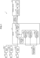
- FIG. 1 is a diagram illustrating an example of a configuration of the information providing system according to a first embodiment.
- An information providing system 1 includes a server 10, a terminal device 20, a plurality of cameras (a camera 30_1, a camera 30_2, ..., and a camera 30_n), and a measurement instrument 40.
- n denotes the number of cameras.
- m denotes the number of channels for the measurement data. The number of cameras and the number of channels for the measurement data are not limited to the numbers illustrated in the drawing. For example, n is 2 or more.
- the server 10 is one example of the information providing apparatus.
- the server 10 acquires data on an image (hereinafter, referred to as "image data") that has been captured by each of the plurality of cameras. Furthermore, the server 10 acquires, for each channel, the pieces of measurement data that have been measured by the respective measurement instrument 40.
- the server 10 may be a cloud server that is connected to a device installed in the inside of the plant by the Internet, or the like.
- the selection unit 11 selects, in accordance with a condition (hereinafter, referred to as a "trigger"), the image data targeted for a merge from among a plurality of pieces of image data.
- the setting information 12 is information for associating the trigger with the camera that captures an image of the image data targeted for the merge.
- the display control unit 13 merges the measurement data with the image data that has been selected by the selection unit 11, and generates a display purpose data file.
- the display control unit 13 provides the generated display purpose data file to the terminal device 20.
- the display purpose data file is an HTML file.
- the terminal device 20 includes a conversion unit 21 and a display unit 22.
- the conversion unit 21 converts the display purpose data file to a format that is able to be displayed by an application installed in the terminal device 20.
- the terminal device 20 functions as a viewer for browsing the display purpose data file that is provided from the server 10.
- the server 10 records the measurement data and the image data, and functions as a logger that provides data that is able to be browsed by the viewer.
- the display unit 22 displays a screen in accordance with the converted display purpose data file.
- the display unit 22 is a display device, such as a display.
- the number of pieces of image data included in the display purpose data file and the camera that has captured the image of the image data are changed in accordance with a result of selection performed by the selection unit 11.
- the number of images and the content of the image that are included in the screen displayed by the display unit 22 are changed in accordance with a trigger.
- FIG. 2 illustrates an example of the screen displayed by the display unit 22.
- image data 300_1, image data 300_2, and measurement data 400_1 are displayed.
- the selection unit 11 has already selected both of the image data 300_1 and the image data 300_2.
- the horizontal axis of the measurement data indicates time.
- the times that are indicated in the measurement data 400_1 and that are associated with the respective image data 300_1 and the image data 300_2 are indicated by connecting lines between the times and the image data 300_1 and the image data 300_2.
- FIG. 2 illustrates an example of the screen displayed by the display unit 22.
- a plurality of pieces of image data may be associated with the single time. Furthermore, when a slider 401_1 illustrated in each of FIG. 2 and FIG. 3 is operated, a portion associated with the range of the time corresponding to the position of the slider 401_1 indicated in the measurement data 400_1 is displayed.
- the image data 300_1 and the measurement data 400_1 are displayed.
- the selection unit 11 has already selected only the image data 300_1.
- the number of the image data that has been selected is one, so that the number of connecting line is just one.
- FIG. 4 similarly to FIG. 2 and FIG. 3 , when the slider 401_1 is operated, a portion associated with the range of the time corresponding to the position of the slider 401_1 indicated in the measurement data 400_1 is displayed.
- the server 10 provides the display purpose data file for displaying the screen 221b instead of the screen 221a.
- the server 10 is able to suppress the file size of the display purpose data file and improve the visibility of the data.
- the server 10 may select the image data by independently using each of the triggers, or may select the image data by using the plurality of triggers in combination.
- the trigger explained here may be a trigger that is referred to when an alarm occurs.
- the server 10 is able to refer to the setting information 12 at the time of occurrence of the alarm, and select the image data in accordance with the trigger.
- the alarm occurs in the case where, for example, a measurement value measured by the measurement instrument 40 exceeds a threshold.
- FIG. 5 is a diagram illustrating an example of a trigger based on the tag number.
- the tag number corresponds to, for example, a channel.
- tag numbers "0001”, “0002”, and “0003” correspond to the measurement data 400_1 illustrated in FIG. 1 , the measurement data 400_2 illustrated in FIG. 1 , and the measurement data 400_3 that is not illustrated, respectively.
- the selection unit 11 selects the image data 300_1 on an image captured by the camera 30_1. Moreover, the occurrence of the alarm is one example of a condition related to the measurement data.
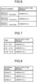
- FIG. 6 is a diagram illustrating an example of a trigger based on a group number. As illustrated in FIG. 6 , the plurality of tag numbers may be grouped. For example, in a group A, the tag numbers "0001" and "0002" are included.
- the selection unit 11 selects the image data 300_1 on the image that is captured by the camera 30_1.
- a plurality of pieces of measurement data may be associated with a single piece of image data. Furthermore, in a trigger, the plurality of pieces of measurement data may be associated with the plurality of pieces of image data.
- the display control unit 13 is able to merge the measurement data that is indicated by the condition with the image data that has been selected by the selection unit 11.
- the selection unit 11 selects one or more pieces of image data that are associated with the one or more pieces of specific measurement data. As a result of this, the selection unit 11 is able to select the image data including the information related to the measurement data targeted for the occurred alarm.
- FIG. 7 is a diagram illustrating an example of the trigger based on the time.
- the period of time such as "0:00 to 8:00", “8:00 to 16:00”, and "16:00 to 24:00", is associated with each of the pieces of image data.
- the selection unit 11 selects, as the image data associated with the period of time "0:00 to 8:00" that includes the time "7:00", the image data 300_1 that is captured by the camera 30_1.
- the selection unit 11 selects one or more pieces of image data that is associated with the specific time zone. As a result of this, the selection unit 11 is able to select the image data that includes useful information by taking into consideration of, for example, the time zone or the like in which the plant instrument is operated.
- the selection unit 11 is able to select the image data that includes the useful information related to the plant instrument.
- FIG. 8 is a diagram illustrating an example of the trigger based on an external signal.
- the selection unit 11 may also select the image data on the basis of the external signal.
- the external signal is a signal that is able to be acquired by the server 10 separately from the measurement data.
- the external signal is provided from, for example, a monitoring system or the like that monitors the plant.
- the selection unit 11 selects the image data 300_1 that is captured by the camera 30_1.
- the selection unit 11 selects one or more pieces of image data that are associated with the specific signal. As a result of this, the selection unit 11 is able to select the image data that includes important information on the basis of the external signal even in the case where an alarm with respect to the measurement data has not occurred.
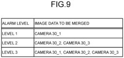
- FIG. 9 is a diagram illustrating an example of the trigger based on an alarm level.
- an alarm level is defined in accordance with a degree of importance of an event that corresponds to a cause of an occurrence of the alarm.
- measurement data indicates the temperature of a fluid that has been measured by a temperature sensor.
- a level 1 is an alarm level in the case where the temperature indicated by the measurement data is in the range of 100°C to 150°C.
- a level 2 is an alarm level in the case where the temperature indicated by the measurement data is in the range of 150°C to 200°C.
- a level 3 is an alarm level in the case where the temperature indicated by the measurement data is in the range of 200°C or more.
- the degree of importance of the event is higher. Furthermore, the degree of importance of the event is higher, physical, human, or economic damage and a cost caused by the event are increased.
- the selection unit 11 selects the image data 300_1 that is captured by the camera 30_1. Furthermore, in the case where the alarm level is the level 2, the selection unit 11 selects the image data 300_2 and the image data 300_3 that are captured by the camera 30_2 and the camera 30_3, respectively. Furthermore, in the case where the alarm level is the level 3, the selection unit 11 selects the image data 300_1, the image data 300_2, and the image data 300_3 that are captured by the camera 30_1, the camera 30_2, and the camera 30_3, respectively.
- each of the processing functions performed by the each of the devices can be implemented by a CPU and by programs analyzed and executed by the CPU or implemented as hardware by wired logic.
- the communication device 100a is a network interface card or the like, and communicates with another server.
- the HDD 100b stores therein the programs and the DBs that operate the functions illustrated in FIG. 1 .
- the processor 100d operates the process that executes each of the functions described above in FIG. 1 or the like by reading the programs that execute the same process as that performed by each of the processing units illustrated in FIG. 1 from the HDD 100b or the like and loading the read programs in the memory 100c.
- the process executes the same functions as those performed by each of the processing units included in the server 10.
- the processor 100d reads, from the HDD 100b or the like, the program having the same function as that performed by a collection unit 151, an evaluation unit 152, and a display control unit 153. Then, the processor 100d executes the process for executing the same process as that performed by the collection unit 151, the evaluation unit 152, and the display control unit 153.
- the server 10 is operated as an information processing apparatus that performs an information processing method by reading and executing the program. Furthermore, the server 10 is also able to implement the same functions as those described above in the embodiment by reading the above described program from a recording medium by a medium reading device and executing the read program.
- the program described in another embodiment are not limited to be executed by the server 10.
- the present invention may also be similarly used in a case in which another computer or a server executes a program or in a case in which another computer and a server cooperatively execute the program with each other.
- the programs may be distributed via a network, such as the Internet. Furthermore, the program may be executed by storing the programs in a recording medium that can be read by a computer readable medium, such as a hard disk, a flexible disk (FD), a CD-ROM, a magneto-optical disk (MO), a digital versatile disk (DVD), or the like, and read the programs from the recording medium by the computer.
- a computer readable medium such as a hard disk, a flexible disk (FD), a CD-ROM, a magneto-optical disk (MO), a digital versatile disk (DVD), or the like
Landscapes
- Engineering & Computer Science (AREA)
- Theoretical Computer Science (AREA)
- Physics & Mathematics (AREA)
- General Physics & Mathematics (AREA)
- General Engineering & Computer Science (AREA)
- Human Computer Interaction (AREA)
- Multimedia (AREA)
- Signal Processing (AREA)
- Automation & Control Theory (AREA)
- Testing And Monitoring For Control Systems (AREA)
- Arrangements For Transmission Of Measured Signals (AREA)
Abstract
A server 10 according to an embodiment includes a selection unit (11) and a display control unit (13). The selection unit (11) selects, when a condition that is set in advance is satisfied, one or more pieces of image data that are associated with the condition from among a plurality of pieces of image data. The display control unit (13) simultaneously displays, when the condition is satisfied, the measurement data that has been measured by a measurement instrument and the image data that has been selected by the selection unit (11) on a single screen.
Description
- The present invention relates to an information providing apparatus, an information providing method, and an information providing program.
- The present invention relates to an information providing apparatus, an information providing method, and an information providing program.
- Conventionally, there is a known technology for efficiently manage data by collectively recording, into a single file, measurement results of a temperature, a flow rate, a pressure, and the like that have been measured by measuring instruments installed in a plant and images that have been captured by a plurality of cameras installed in the plant (for example, see
Japanese Patent No. 5979064 - Hereinafter, a process of recording the measurement results and the images into the single file or the like is referred to as a merge. Information on the merged file is sometimes displayed on a single screen. With the technology described in
Japanese Patent No. 5979064 - In contrast, with the conventional technology, the visibility of the data is sometimes reduced. For example, all of the plurality of images displayed on the single screen are not always needed information for a person who browses the screen (for example, an administrator of a plant). If an image that is unnecessary for the browsing person is displayed on the screen, it is difficult to view the screen and it is thus difficult to efficiently obtain the necessary information.
- It is an object of the present invention to at least partially solve the problems in the conventional technology.
- The above and other objects, features, advantages and technical and industrial significance of this invention will be better understood by reading the following detailed description of presently preferred embodiments of the invention, when considered in connection with the accompanying drawings.
-
-
FIG. 1 is a diagram illustrating an example of a configuration of an information providing system according to a first embodiment; -
FIG. 2 is a diagram illustrating an example of a screen; -
FIG. 3 is a diagram illustrating an example of a screen; -
FIG. 4 is a diagram illustrating an example of a screen; -
FIG. 5 is a diagram illustrating an example of a trigger based on a tag number; -
FIG. 6 is a diagram illustrating an example of a trigger based on a group number; -
FIG. 7 is a diagram illustrating an example of a trigger based on time; -
FIG. 8 is a diagram illustrating an example of a trigger based on an external signal; -
FIG. 9 is a diagram illustrating an example of a trigger based on an alarm level; -
FIG. 10 is a flowchart illustrating the flow of a process performed by an information providing apparatus according to the first embodiment; and -
FIG. 11 is a diagram illustrating an example of a hardware configuration. - Preferred embodiments of an information providing apparatus, an information providing method, and an information providing program disclosed in the present invention will be described in detail below with reference to the accompanying drawings. Furthermore, the present invention is not limited to the embodiments. In addition, the same components are denoted by the same reference numerals and an overlapping description will be omitted. Each of the embodiments can be used in any appropriate combination as long as they do not conflict with each other. Furthermore, a protocol converter is one example of the information processing apparatus.
- The information providing apparatus according to the present embodiment provides data obtained by merging measurement data that is a measurement result obtained by a measuring instrument that is installed in a facility, such as a plant, and image data on an image captured by a camera. Further, the image may be a still image or may be a moving image.
-
FIG. 1 is a diagram illustrating an example of a configuration of the information providing system according to a first embodiment. Aninformation providing system 1 includes aserver 10, aterminal device 20, a plurality of cameras (a camera 30_1, a camera 30_2, ..., and a camera 30_n), and a measurement instrument 40. Here, n denotes the number of cameras. In addition, m denotes the number of channels for the measurement data. The number of cameras and the number of channels for the measurement data are not limited to the numbers illustrated in the drawing. For example, n is 2 or more. Theserver 10 is one example of the information providing apparatus. - The channel may be one that corresponds to a location in which a target object that is to be measured by the measurement instrument 40 is present. Furthermore, the channel may be one that corresponds to each of the plurality of measurement instruments 40.
- The
server 10 acquires data on an image (hereinafter, referred to as "image data") that has been captured by each of the plurality of cameras. Furthermore, theserver 10 acquires, for each channel, the pieces of measurement data that have been measured by the respective measurement instrument 40. - For example, the measurement instrument 40 is a sensor for measuring a physical amount of the plant instrument that is installed in the plant. The plant instrument is a tank, a pipe, a furnace, or the like. Furthermore, the physical amount is a temperature, pressure, a flow rate, or the like.
- The
server 10 periodically acquires the acquired image data and the measurement data and holds the acquired image data and the measurement data. Furthermore, theserver 10 may be provided in an inside of the plant in which the measurement instrument and the cameras are installed. At this time, theserver 10 is connected to the plurality of cameras, the measurement instrument 40, and theterminal device 20 via a network, such as Ethernet (registered trademark), that is provided in the inside of the plant. - Furthermore, the
server 10 may be a cloud server that is connected to a device installed in the inside of the plant by the Internet, or the like. - The
server 10 includes aselection unit 11 and a display control unit 13. Furthermore, theserver 10 stores therein settinginformation 12. - The
selection unit 11 selects, in accordance with a condition (hereinafter, referred to as a "trigger"), the image data targeted for a merge from among a plurality of pieces of image data. Thesetting information 12 is information for associating the trigger with the camera that captures an image of the image data targeted for the merge. - The display control unit 13 merges the measurement data with the image data that has been selected by the
selection unit 11, and generates a display purpose data file. The display control unit 13 provides the generated display purpose data file to theterminal device 20. For example, the display purpose data file is an HTML file. - The
terminal device 20 includes a conversion unit 21 and a display unit 22. The conversion unit 21 converts the display purpose data file to a format that is able to be displayed by an application installed in theterminal device 20. - The
terminal device 20 functions as a viewer for browsing the display purpose data file that is provided from theserver 10. In contrast, theserver 10 records the measurement data and the image data, and functions as a logger that provides data that is able to be browsed by the viewer. - The display unit 22 displays a screen in accordance with the converted display purpose data file. The display unit 22 is a display device, such as a display.
- Here, the number of pieces of image data included in the display purpose data file and the camera that has captured the image of the image data are changed in accordance with a result of selection performed by the
selection unit 11. In other words, the number of images and the content of the image that are included in the screen displayed by the display unit 22 are changed in accordance with a trigger. -
FIG. 2 illustrates an example of the screen displayed by the display unit 22. On ascreen 221a illustrated inFIG. 2 , image data 300_1, image data 300_2, and measurement data 400_1 are displayed. In this case, theselection unit 11 has already selected both of the image data 300_1 and the image data 300_2. Furthermore, the horizontal axis of the measurement data indicates time. As illustrated inFIG. 2 , the times that are indicated in the measurement data 400_1 and that are associated with the respective image data 300_1 and the image data 300_2 are indicated by connecting lines between the times and the image data 300_1 and the image data 300_2. Furthermore, as illustrated inFIG. 3 , a plurality of pieces of image data (here, both of the image data 300_1 and the image data 300_2) may be associated with the single time. Furthermore, when a slider 401_1 illustrated in each ofFIG. 2 and FIG. 3 is operated, a portion associated with the range of the time corresponding to the position of the slider 401_1 indicated in the measurement data 400_1 is displayed. - In contrast, on a
screen 221b illustrated inFIG. 4 , the image data 300_1 and the measurement data 400_1 are displayed. In this case, theselection unit 11 has already selected only the image data 300_1. In the example illustrated inFIG. 4 , unlikeFIG. 2 and FIG. 3 , the number of the image data that has been selected is one, so that the number of connecting line is just one. Furthermore, in alsoFIG. 4 , similarly toFIG. 2 and FIG. 3 , when the slider 401_1 is operated, a portion associated with the range of the time corresponding to the position of the slider 401_1 indicated in the measurement data 400_1 is displayed. - It is conceivable that the image data that is needed by the browsing person varies according to a trigger. For example, in a situation in which the browsing person needs the image data 300_1 but does not need the image data 300_2, the
server 10 provides the display purpose data file for displaying thescreen 221b instead of thescreen 221a. As a result of this, theserver 10 is able to suppress the file size of the display purpose data file and improve the visibility of the data. - In the following, a specific example of the setting
information 12 will be described. Theserver 10 may select the image data by independently using each of the triggers, or may select the image data by using the plurality of triggers in combination. Furthermore, the trigger explained here may be a trigger that is referred to when an alarm occurs. For example, theserver 10 is able to refer to the settinginformation 12 at the time of occurrence of the alarm, and select the image data in accordance with the trigger. The alarm occurs in the case where, for example, a measurement value measured by the measurement instrument 40 exceeds a threshold. -
FIG. 5 is a diagram illustrating an example of a trigger based on the tag number. The tag number corresponds to, for example, a channel. - It is assumed that the tag numbers "0001", "0002", and "0003" correspond to the measurement data 400_1 illustrated in
FIG. 1 , the measurement data 400_2 illustrated inFIG. 1 , and the measurement data 400_3 that is not illustrated, respectively. - In the example illustrated in
FIG. 5 , in the case where the measurement value indicated by the measurement data 400_1 that corresponds to the tag number "0001" exceeds the threshold (in the case where an alarm occurs), theselection unit 11 selects the image data 300_1 on an image captured by the camera 30_1. Moreover, the occurrence of the alarm is one example of a condition related to the measurement data. -
FIG. 6 is a diagram illustrating an example of a trigger based on a group number. As illustrated inFIG. 6 , the plurality of tag numbers may be grouped. For example, in a group A, the tag numbers "0001" and "0002" are included. - In the example illustrated in
FIG. 6 , in the case where the measurement value indicated by the measurement data 400_1 and the measurement data 400_2 that correspond to the tag numbers "0001" and "0002", respectively, and that are included in the group A exceed the threshold (in the case where an alarm has occurred), theselection unit 11 selects the image data 300_1 on the image that is captured by the camera 30_1. - Furthermore, as illustrated in
FIG. 6 , in a trigger, a plurality of pieces of measurement data may be associated with a single piece of image data. Furthermore, in a trigger, the plurality of pieces of measurement data may be associated with the plurality of pieces of image data. - Furthermore, in the examples illustrated in
FIG. 5 andFIG. 6 , the display control unit 13 is able to merge the measurement data that is indicated by the condition with the image data that has been selected by theselection unit 11. - In this way, in the case where the condition that an alarm occurs with respect to one or more pieces of specific measurement data measured by the measurement instrument is satisfied, the
selection unit 11 selects one or more pieces of image data that are associated with the one or more pieces of specific measurement data. As a result of this, theselection unit 11 is able to select the image data including the information related to the measurement data targeted for the occurred alarm. -
FIG. 7 is a diagram illustrating an example of the trigger based on the time. For example, the period of time, such as "0:00 to 8:00", "8:00 to 16:00", and "16:00 to 24:00", is associated with each of the pieces of image data. - In the example illustrated in
FIG. 7 , in the case where the measurement value indicated by one of the measurement data exceeds the threshold at the time "7:00" (in the case where an alarm has occurred), theselection unit 11 selects, as the image data associated with the period of time "0:00 to 8:00" that includes the time "7:00", the image data 300_1 that is captured by the camera 30_1. - In this way, in the case where the condition that the measurement data is measured by the measurement instrument in a specific time zone is satisfied, the
selection unit 11 selects one or more pieces of image data that is associated with the specific time zone. As a result of this, theselection unit 11 is able to select the image data that includes useful information by taking into consideration of, for example, the time zone or the like in which the plant instrument is operated. - For example, it is conceivable that it is not possible to obtain useful information even if image data obtained by capturing an image of a certain plant instrument is selected in the time zone in which the certain plant instrument is not operated. In contrast, by associating in advance the operating time zone of the plant instrument with the image data obtained by capturing the image of the plant instrument, the
selection unit 11 is able to select the image data that includes the useful information related to the plant instrument. -
FIG. 8 is a diagram illustrating an example of the trigger based on an external signal. Theselection unit 11 may also select the image data on the basis of the external signal. The external signal is a signal that is able to be acquired by theserver 10 separately from the measurement data. The external signal is provided from, for example, a monitoring system or the like that monitors the plant. - In the example illustrated in
FIG. 8 , in the case where theserver 10 receives a signal X, theselection unit 11 selects the image data 300_1 that is captured by the camera 30_1. - In this way, in the case where the condition that the information providing apparatus has received a specific signal is satisfied, the
selection unit 11 selects one or more pieces of image data that are associated with the specific signal. As a result of this, theselection unit 11 is able to select the image data that includes important information on the basis of the external signal even in the case where an alarm with respect to the measurement data has not occurred. -
FIG. 9 is a diagram illustrating an example of the trigger based on an alarm level. For example, an alarm level is defined in accordance with a degree of importance of an event that corresponds to a cause of an occurrence of the alarm. - For example, it is assumed that measurement data indicates the temperature of a fluid that has been measured by a temperature sensor. A
level 1 is an alarm level in the case where the temperature indicated by the measurement data is in the range of 100°C to 150°C. A level 2 is an alarm level in the case where the temperature indicated by the measurement data is in the range of 150°C to 200°C. A level 3 is an alarm level in the case where the temperature indicated by the measurement data is in the range of 200°C or more. - As the alarm level is higher, the degree of importance of the event is higher. Furthermore, the degree of importance of the event is higher, physical, human, or economic damage and a cost caused by the event are increased.
- In the example illustrated in
FIG. 9 , in the case where the alarm level is thelevel 1, theselection unit 11 selects the image data 300_1 that is captured by the camera 30_1. Furthermore, in the case where the alarm level is thelevel 2, theselection unit 11 selects the image data 300_2 and the image data 300_3 that are captured by the camera 30_2 and the camera 30_3, respectively. Furthermore, in the case where the alarm level is thelevel 3, theselection unit 11 selects the image data 300_1, the image data 300_2, and the image data 300_3 that are captured by the camera 30_1, the camera 30_2, and the camera 30_3, respectively. - In this way, in the case where the condition that an alarm of the specific level occurs with respect to one or more pieces of specific measurement data that are measured by the measurement instrument is satisfied, the
selection unit 11 selects one or more pieces of image data that are associated with the level. As a result of this, theselection unit 11 selects the image data from which an amount of information in accordance with the level of the alarm, that is, the degree of importance, can be obtained. - For example, as described above, in the case where the measurement data indicates the temperature of the fluid, the camera 30_1 captures an image of a tank for the fluid. Furthermore, for example, the camera 30_2 captures an image of a heater that heats the fluid. Furthermore, for example, the camera 30_3 captures an image of a control device that is used to control the degree of heating by the heater.
- In this case, in the case where the alarm level in which the degree of importance is especially high is the
level 3, the browsing person is able to further certainly find out the cause of the event by checking the situation of the tank, the heater, and the control device. - The
selection unit 11 may select the image data on the basis of a rise rate of the measurement value indicated by the measurement data in time series. - First, the
selection unit 11 measures the period of time needed for the measurement value indicated by the measurement data to increase from the value corresponding to thealarm level 1 to the value corresponding to thealarm level 2. Then, theselection unit 11 calculates the rise rate as (V2 - V1)/t, where the value corresponding to thealarm level 1 is denoted by V1, the value corresponding to thealarm level 2 is denoted by V2, and the period of time is denoted by t. - For example, in the case where the rise rate is less than the threshold (t is long), the
selection unit 11 selects the image data 300_1. In contrast, in the case where the rise rate is equal to or larger than the threshold (t is short), theselection unit 11 selects the image data 300_2. In other words, the image data is associated with the rise rate. The image data 300_1 is associated with the rise rate that is less than the threshold. The image data 300_2 is associated with the rise rate that is equal to or larger than the threshold. - It is conceivable that the degree of importance of the event is higher as the rise rate is higher. For example, in the case where the temperature and the pressure of the tank rises sharply, this may possibly lead to a serious accident resulting in, for example, damage of the tank.
- Furthermore, the
selection unit 11 allocates the measurement date and time to the selected image data in time series and holds the allocated information. Then, theselection unit 11 compares the pieces of image data that are allocated in time series, and selects the image data having a large difference (a large change over time). - For example, the
selection unit 11 compares the image data allocated to each time with the image data allocated to the time adjacent to the time to be compared, and calculates the difference. For example, the difference between the pieces of image data is, for example, a sum of the differences of the pixel values of the adjacent pixels. - Furthermore, the
selection unit 11 may also select the image data that has been captured by the camera in which the setting that corresponds to the trigger has been made, instead of selecting the image data that has been captured by the camera corresponding to the trigger. - For example, examples of the camera include a zoom magnification of the camera that captures the image, a switch between an actual video image and a thermograph, and a switch between on and off of light.
- In this way, in the case where the condition that the measurement data measured by the measurement instrument rises at a specific rise rate is satisfied, the
selection unit 11 selects the image data in which the magnitude of the change in time series is equal to or larger than the threshold from among the pieces of image data in time series that are associated with the rise rate. As a result of this, theselection unit 11 is able to select the image data that indicates the cause of the rise in the measurement data. - In the following, the flow of the process performed by the
server 10 will be described with reference toFIG. 10. FIG. 10 is a flowchart illustrating the flow of the process performed by the information providing apparatus (the server 10) according to the first embodiment. - As illustrated in
FIG. 10 , first, theserver 10 receives the setting of the trigger and the image data to be selected (Steps S101 and S102). Here, theserver 10 starts to record the measurement data and the image data (Step S103). - Then, the
server 10 simultaneously performs recording processes on the measurement data and the image data (Step S2). Theserver 10 acquires the measurement data that has been measured by the measurement instrument 40 (Step S104), and holds the measured measurement data (Step S105). Furthermore, theserver 10 acquires the image data that has been captured by the plurality of cameras (Step S106), and holds the acquired image data (Step S107). - If the trigger that has been set at Step S101 has occurred (Yes at Step S108), the
server 10 selects the image data corresponding to the trigger (Step S109). Then, theserver 10 holds the display purpose data file that is obtained by merging the measurement data with the selected image data (Step S 110). - If the trigger has not occurred (No at Step S108), or if the process at Step S110 has been ended, the
server 10 determines whether or not the recording processes of the measurement data and the image data are to be ended (Step S111). For example, if specified time has elapsed after the start of the record (Step S103), theserver 10 determines to end the recording processes. - If the
server 10 does not end the recording processes (No at Step S111), theserver 10 returns to the processes at Step S2 and repeats the processes. - If the
server 10 ends the recording processes (Yes at Step S111), theserver 10 outputs the display purpose data file to the terminal device 20 (Step S112). - After that, the
server 10 allows theterminal device 20 to convert the display purpose data file (Step S113), and simultaneously display the measurement value data and the image data (Step S114). - As described above, the
server 10 includes theselection unit 11 and the display control unit 13. In the case where the condition that is set in advance is satisfied, theselection unit 11 selects one or more pieces of image data that are associated with the condition from among the plurality of pieces of image data. In the case where the condition is satisfied, the display control unit 13 simultaneously displays, on the single screen, the measurement data that has been measured by the measurement instrument and the image data that has been selected by theselection unit 11. - In this way, the
server 10 selects the needed image data in accordance with the condition, merges the selected image data with the measurement data, and displays the merged data on the single screen. As a result of this, it is possible to reduce the size of the data that has been merged, and it is also possible to improve the visibility of the data on the screen. - The flow of the processes, the control procedures, the specific names, and the information containing various kinds of data or parameters indicated in the above specification and drawings can be arbitrarily changed unless otherwise stated.
- Furthermore, the components of each unit illustrated in the drawings are only for conceptually illustrating the functions thereof and are not always physically configured as illustrated in the drawings. In other words, the specific shape of a separate or integrated device is not limited to the drawings. Specifically, all or part of the device can be configured by functionally or physically separating or integrating any of the units depending on various loads or use conditions.
- Furthermore, all or any part of each of the processing functions performed by the each of the devices can be implemented by a CPU and by programs analyzed and executed by the CPU or implemented as hardware by wired logic.
- In the following, an example of a hardware configuration of the
server 10 will be described.FIG. 11 is a diagram illustrating an example of the hardware configuration. As illustrated inFIG. 11 , theserver 10 includes acommunication device 100a, a hard disk drive (HDD) 100b, amemory 100c, and aprocessor 100d. Furthermore, each of the units illustrated inFIG. 11 is connected by a bus or the like with each other. - The
communication device 100a is a network interface card or the like, and communicates with another server. TheHDD 100b stores therein the programs and the DBs that operate the functions illustrated inFIG. 1 . - The
processor 100d operates the process that executes each of the functions described above inFIG. 1 or the like by reading the programs that execute the same process as that performed by each of the processing units illustrated inFIG. 1 from theHDD 100b or the like and loading the read programs in thememory 100c. For example, the process executes the same functions as those performed by each of the processing units included in theserver 10. Specifically, theprocessor 100d reads, from theHDD 100b or the like, the program having the same function as that performed by a collection unit 151, an evaluation unit 152, and a display control unit 153. Then, theprocessor 100d executes the process for executing the same process as that performed by the collection unit 151, the evaluation unit 152, and the display control unit 153. - In this way, the
server 10 is operated as an information processing apparatus that performs an information processing method by reading and executing the program. Furthermore, theserver 10 is also able to implement the same functions as those described above in the embodiment by reading the above described program from a recording medium by a medium reading device and executing the read program. In addition, the program described in another embodiment are not limited to be executed by theserver 10. For example, the present invention may also be similarly used in a case in which another computer or a server executes a program or in a case in which another computer and a server cooperatively execute the program with each other. - The programs may be distributed via a network, such as the Internet. Furthermore, the program may be executed by storing the programs in a recording medium that can be read by a computer readable medium, such as a hard disk, a flexible disk (FD), a CD-ROM, a magneto-optical disk (MO), a digital versatile disk (DVD), or the like, and read the programs from the recording medium by the computer.
- Some examples of combinations of the disclosed technical features are described in the following.
- According to an aspect of an embodiment, it is possible to improve the visibility of data.
- Although the invention has been described with respect to specific embodiments for a complete and clear disclosure, the appended claims are not to be thus limited but are to be construed as embodying all modifications and alternative constructions that may occur to one skilled in the art that fairly fall within the basic teaching herein set forth.
Claims (8)
- An information providing apparatus comprising:a selection unit (11) that selects, when a condition that is set in advance is satisfied, one or more pieces of image data that are associated with the condition from among a plurality of pieces of image data; anda display control unit (13) that simultaneously displays, when the condition is satisfied, measurement data that has been measured by a measurement instrument and the image data that has been selected by the selection unit (11) on a single screen.
- The information providing apparatus according to claim 1, wherein, when the condition related to one or more pieces of specific measurement data that are measured by the measurement instrument is satisfied, the selection unit (11) selects one or more pieces of the image data that are associated with one or more pieces of the specific measurement data.
- The information providing apparatus according to claim 1, wherein, when the condition that the measurement data is measured by the measurement instrument in a specific time zone is satisfied, the selection unit (11) selects one or more pieces of the image data that are associated with the specific time zone.
- The information providing apparatus according to claim 1, wherein, when the condition that the information providing apparatus has received a specific signal is satisfied, the selection unit (11) selects one or more pieces of the image data that are associated with the specific signal.
- The information providing apparatus according to claim 1, wherein, when the condition that an alarm with a specific level occurs with respect to one or more pieces of specific measurement data that are measured by the measurement instrument is satisfied, the selection unit (11) selects one or more pieces of the image data that are associated with the level.
- The information providing apparatus according to claim 1, wherein, when the condition that a rise rate of the measurement data measured by the measurement instrument is equal to or larger than a threshold is satisfied, the selection unit (11) selects the image data that is associated with the rise rate that is equal to or larger than the threshold.
- An information providing method that causes a computer to execute a process comprising:selecting, when a condition that is set in advance is satisfied, one or more pieces of image data that are associated with the condition from among a plurality of pieces of image data; anddisplaying simultaneously, when the condition is satisfied, measurement data that has been measured by a measurement instrument and the selected image data on a single screen.
- An information providing program causing a computer to execute processing comprising:selecting, when a condition that is set in advance is satisfied, one or more pieces of image data that are associated with the condition from among a plurality of pieces of image data; anddisplaying simultaneously, when the condition is satisfied, measurement data that has been measured by a measurement instrument and the selected image data on a single screen.
Applications Claiming Priority (1)
| Application Number | Priority Date | Filing Date | Title |
|---|---|---|---|
| JP2023101939A JP2025002032A (en) | 2023-06-21 | 2023-06-21 | Information providing device, information providing method and information providing program |
Publications (1)
| Publication Number | Publication Date |
|---|---|
| EP4481706A1 true EP4481706A1 (en) | 2024-12-25 |
Family
ID=91486439
Family Applications (1)
| Application Number | Title | Priority Date | Filing Date |
|---|---|---|---|
| EP24181630.5A Pending EP4481706A1 (en) | 2023-06-21 | 2024-06-12 | Information providing apparatus, information providing method, and information providing program |
Country Status (4)
| Country | Link |
|---|---|
| US (1) | US20240428483A1 (en) |
| EP (1) | EP4481706A1 (en) |
| JP (1) | JP2025002032A (en) |
| CN (1) | CN119179416A (en) |
Citations (5)
| Publication number | Priority date | Publication date | Assignee | Title |
|---|---|---|---|---|
| JP2000330624A (en) * | 1999-05-25 | 2000-11-30 | Mitsubishi Electric Corp | Plant monitoring system |
| US9025937B1 (en) * | 2011-11-03 | 2015-05-05 | The United States Of America As Represented By The Secretary Of The Navy | Synchronous fusion of video and numerical data |
| US20150241993A1 (en) * | 2013-05-23 | 2015-08-27 | Allied Telesis Holdings Kabushiki Kaisha | Graphical user interface and video frames for a sensor based detection system |
| JP5979064B2 (en) | 2013-04-02 | 2016-08-24 | 横河電機株式会社 | Recorder |
| WO2023048766A1 (en) * | 2021-09-22 | 2023-03-30 | Halo Smart Solutions, Inc. | Heat-not-burn activity detection device, system and method |
Family Cites Families (4)
| Publication number | Priority date | Publication date | Assignee | Title |
|---|---|---|---|---|
| US20060177119A1 (en) * | 2002-10-25 | 2006-08-10 | Mcpheely Bernard M | Digital diagnosti video system for manufacturing and industrial process |
| JP2016015719A (en) * | 2014-05-20 | 2016-01-28 | アライドテレシスホールディングス株式会社 | Graphic user interface and video frame for sensor-based detection systems |
| JP7739906B2 (en) * | 2021-09-29 | 2025-09-17 | オムロン株式会社 | Control System |
| EP4500501A1 (en) * | 2022-03-30 | 2025-02-05 | Johnson Controls Tyco IP Holdings LLP | Premises intersystem operations |
-
2023
- 2023-06-21 JP JP2023101939A patent/JP2025002032A/en active Pending
-
2024
- 2024-06-06 US US18/735,386 patent/US20240428483A1/en active Pending
- 2024-06-12 EP EP24181630.5A patent/EP4481706A1/en active Pending
- 2024-06-18 CN CN202410782367.7A patent/CN119179416A/en active Pending
Patent Citations (5)
| Publication number | Priority date | Publication date | Assignee | Title |
|---|---|---|---|---|
| JP2000330624A (en) * | 1999-05-25 | 2000-11-30 | Mitsubishi Electric Corp | Plant monitoring system |
| US9025937B1 (en) * | 2011-11-03 | 2015-05-05 | The United States Of America As Represented By The Secretary Of The Navy | Synchronous fusion of video and numerical data |
| JP5979064B2 (en) | 2013-04-02 | 2016-08-24 | 横河電機株式会社 | Recorder |
| US20150241993A1 (en) * | 2013-05-23 | 2015-08-27 | Allied Telesis Holdings Kabushiki Kaisha | Graphical user interface and video frames for a sensor based detection system |
| WO2023048766A1 (en) * | 2021-09-22 | 2023-03-30 | Halo Smart Solutions, Inc. | Heat-not-burn activity detection device, system and method |
Also Published As
| Publication number | Publication date |
|---|---|
| JP2025002032A (en) | 2025-01-09 |
| CN119179416A (en) | 2024-12-24 |
| US20240428483A1 (en) | 2024-12-26 |
Similar Documents
| Publication | Publication Date | Title |
|---|---|---|
| JP3634845B2 (en) | Temperature display device and temperature monitoring system | |
| CN101127892B (en) | Monitoring equipment and filter calibration method | |
| KR20090006295A (en) | Cell slide reading device, cell slide reading system, cell slide reading method and recording medium using the same | |
| EP2840557B1 (en) | Image processing system, server device, image pickup device and image evaluation method | |
| CN108391147B (en) | Display control device and display control method | |
| US8411141B2 (en) | Video processing method for reducing the load of viewing | |
| KR20120015819A (en) | Method for generating parametric data for non-contact structure displacement measurement | |
| CN104677504B (en) | Determining device and determining method | |
| CN113222988A (en) | Infusion tube liquid level identification method based on deep learning and image overdivision | |
| US20170208242A1 (en) | Information processing apparatus, information processing method, and computer-readable non-transitory recording medium | |
| US10878555B2 (en) | Image processing system, image processing device, and non-transitory computer readable recording medium | |
| US20240428483A1 (en) | Information providing apparatus, information providing method, and non-transitory computer readable recording medium | |
| EP2722817A1 (en) | Motion image region identification device and method thereof | |
| CN112365742A (en) | LDW function test method, device, test equipment and storage medium | |
| CN112579416B (en) | Page loading duration statistical method, terminal and readable storage medium | |
| JP7417426B2 (en) | Anomaly detection device and anomaly detection method | |
| CN116016805B (en) | Data processing method, device, electronic device and storage medium | |
| US20120127303A1 (en) | Detecting System Component Failures In A Computing System | |
| US20150371419A1 (en) | Inspection data display control apparatus, method, and recording medium | |
| US10657626B2 (en) | Image processing apparatus, image processing system, and recording medium | |
| US20140293044A1 (en) | Recorder | |
| US9449251B2 (en) | Image processing apparatus, image processing method, and medium | |
| KR100746484B1 (en) | Remote water quality monitoring system using water flea activity measurement using CD camera | |
| JP2001228028A (en) | Infrared thermal imaging device | |
| KR102893407B1 (en) | Virtual gauge based plant monitoring system and method thereof |
Legal Events
| Date | Code | Title | Description |
|---|---|---|---|
| PUAI | Public reference made under article 153(3) epc to a published international application that has entered the european phase |
Free format text: ORIGINAL CODE: 0009012 |
|
| STAA | Information on the status of an ep patent application or granted ep patent |
Free format text: STATUS: THE APPLICATION HAS BEEN PUBLISHED |
|
| AK | Designated contracting states |
Kind code of ref document: A1 Designated state(s): AL AT BE BG CH CY CZ DE DK EE ES FI FR GB GR HR HU IE IS IT LI LT LU LV MC ME MK MT NL NO PL PT RO RS SE SI SK SM TR |
|
| STAA | Information on the status of an ep patent application or granted ep patent |
Free format text: STATUS: REQUEST FOR EXAMINATION WAS MADE |
|
| 17P | Request for examination filed |
Effective date: 20250624 |
|
| STAA | Information on the status of an ep patent application or granted ep patent |
Free format text: STATUS: EXAMINATION IS IN PROGRESS |