EP4481530A1 - Air vehicle control to avoid collision against objects upon potential failure - Google Patents
Air vehicle control to avoid collision against objects upon potential failure Download PDFInfo
- Publication number
- EP4481530A1 EP4481530A1 EP24166963.9A EP24166963A EP4481530A1 EP 4481530 A1 EP4481530 A1 EP 4481530A1 EP 24166963 A EP24166963 A EP 24166963A EP 4481530 A1 EP4481530 A1 EP 4481530A1
- Authority
- EP
- European Patent Office
- Prior art keywords
- air vehicle
- uav
- flight state
- risk
- determining
- Prior art date
- Legal status (The legal status is an assumption and is not a legal conclusion. Google has not performed a legal analysis and makes no representation as to the accuracy of the status listed.)
- Granted
Links
Images

Classifications
-
- G—PHYSICS
- G05—CONTROLLING; REGULATING
- G05D—SYSTEMS FOR CONTROLLING OR REGULATING NON-ELECTRIC VARIABLES
- G05D1/00—Control of position, course, altitude or attitude of land, water, air or space vehicles, e.g. using automatic pilots
- G05D1/80—Arrangements for reacting to or preventing system or operator failure
- G05D1/85—Fail-safe operations, e.g. limp home mode
- G05D1/854—Fail-safe operations, e.g. limp home mode in response to motor or actuator failures
-
- B—PERFORMING OPERATIONS; TRANSPORTING
- B64—AIRCRAFT; AVIATION; COSMONAUTICS
- B64U—UNMANNED AERIAL VEHICLES [UAV]; EQUIPMENT THEREFOR
- B64U20/00—Constructional aspects of UAVs
- B64U20/80—Arrangement of on-board electronics, e.g. avionics systems or wiring
- B64U20/87—Mounting of imaging devices, e.g. mounting of gimbals
-
- B—PERFORMING OPERATIONS; TRANSPORTING
- B64—AIRCRAFT; AVIATION; COSMONAUTICS
- B64U—UNMANNED AERIAL VEHICLES [UAV]; EQUIPMENT THEREFOR
- B64U10/00—Type of UAV
- B64U10/25—Fixed-wing aircraft
-
- G—PHYSICS
- G05—CONTROLLING; REGULATING
- G05D—SYSTEMS FOR CONTROLLING OR REGULATING NON-ELECTRIC VARIABLES
- G05D1/00—Control of position, course, altitude or attitude of land, water, air or space vehicles, e.g. using automatic pilots
- G05D1/60—Intended control result
- G05D1/617—Safety or protection, e.g. defining protection zones around obstacles or avoiding hazards
- G05D1/622—Obstacle avoidance
-
- G—PHYSICS
- G06—COMPUTING OR CALCULATING; COUNTING
- G06N—COMPUTING ARRANGEMENTS BASED ON SPECIFIC COMPUTATIONAL MODELS
- G06N20/00—Machine learning
-
- B—PERFORMING OPERATIONS; TRANSPORTING
- B64—AIRCRAFT; AVIATION; COSMONAUTICS
- B64U—UNMANNED AERIAL VEHICLES [UAV]; EQUIPMENT THEREFOR
- B64U2201/00—UAVs characterised by their flight controls
- B64U2201/10—UAVs characterised by their flight controls autonomous, i.e. by navigating independently from ground or air stations, e.g. by using inertial navigation systems [INS]
-
- G—PHYSICS
- G05—CONTROLLING; REGULATING
- G05D—SYSTEMS FOR CONTROLLING OR REGULATING NON-ELECTRIC VARIABLES
- G05D2101/00—Details of software or hardware architectures used for the control of position
- G05D2101/10—Details of software or hardware architectures used for the control of position using artificial intelligence [AI] techniques
- G05D2101/15—Details of software or hardware architectures used for the control of position using artificial intelligence [AI] techniques using machine learning, e.g. neural networks
-
- G—PHYSICS
- G05—CONTROLLING; REGULATING
- G05D—SYSTEMS FOR CONTROLLING OR REGULATING NON-ELECTRIC VARIABLES
- G05D2107/00—Specific environments of the controlled vehicles
- G05D2107/10—Outdoor regulated spaces
- G05D2107/17—Spaces with priority for humans, e.g. populated areas, pedestrian ways, parks or beaches
-
- G—PHYSICS
- G05—CONTROLLING; REGULATING
- G05D—SYSTEMS FOR CONTROLLING OR REGULATING NON-ELECTRIC VARIABLES
- G05D2109/00—Types of controlled vehicles
- G05D2109/20—Aircraft, e.g. drones
- G05D2109/25—Rotorcrafts
- G05D2109/254—Flying platforms, e.g. multicopters
Definitions
- aspects of the present disclosure relate to vehicle control, and more specifically aspects of the invention relate to air vehicle (e.g., unmanned aerial vehicle (UAV)) control to avoid collision against objects on the ground in the case of air vehicle failure.
- air vehicle e.g., unmanned aerial vehicle (UAV)
- Safety and risk assessment for UAVs, and other air vehicles, is critically important.
- governmental regulations in various jurisdictions require a UAV operator to undertake a risk assessment (e.g., a Specific Operations Risk Assessment (SORA)) for operation of the UAV.
- SORA Specific Operations Risk Assessment
- This can include a ground risk assessment that determines the risk to objects (e.g., any animate or inanimate object, including persons, animals, obstacles, structures, vehicles, and any other suitable objects) protruding from the ground, from operation of the UAV.
- objects e.g., any animate or inanimate object, including persons, animals, obstacles, structures, vehicles, and any other suitable objects
- a loss of propulsion by the UAV could cause the air vehicle to lose control and fall to the ground, or otherwise impact (e.g., collide with) objects on the ground.
- a loss of propulsion can be caused by a loss of power, a loss of engine, an air collision, a projectile impact, or any other causational occurrence.
- One or more techniques described herein can be used to reduce the impact of potential UAV failure (e.g., loss of propulsion) on objects on the ground.
- Embodiments include a method.
- the method includes receiving a flight state for an air vehicle.
- the method further includes identifying an object below the air vehicle, using one or more sensors.
- the method further includes determining a risk that the air vehicle will collide with the object should the air vehicle later lose propulsion.
- the method further includes protecting against the air vehicle colliding with the object, based on the determined risk.
- Embodiments further include a non-transitory computer-readable medium containing computer program code that, when executed by operation of one or more computer processors, performs operations.
- the operations include receiving a flight state for an air vehicle.
- the operations further include identifying an object below the air vehicle, using one or more sensors.
- the operations further include determining a risk that the air vehicle will collide with the object should the air vehicle later lose propulsion.
- the operations further include protecting against the air vehicle colliding with the object, based on the determined risk.
- Embodiments further include an unmanned aerial vehicle (UAV), including a computer processor and a memory having instructions stored thereon which, when executed on the computer processor, performs operations.
- the operations include identifying a flight state for the UAV.
- the operations further include receiving a corrected flight state for the UAV, wherein the corrected flight state is calculated based on identifying an object below the UAV using one or more sensors and determining a risk that the UAV will collide with the object should the UAV later lose propulsion.
- the operations further include automatically controlling the UAV to operate using the corrected flight state.
- the present disclosure describes techniques to avoid an air vehicle (e.g., a UAV) impacting (e.g., colliding with) objects below the air vehicle (e.g., on the ground) in the event of a loss of propulsion.
- objects can include any animate or inanimate object, including persons, animals, obstacles, structures, vehicles, and any other suitable objects.
- FTSs flight termination systems
- existing solutions typically try to reduce ground risk by reducing the negative effect of a collision by the UAV with objects on the ground.
- FTSs flight termination systems
- these FTS add significant weight and drag to the UAV, greatly reducing its range (among other drawbacks).
- ground risk safety buffers can be used to limit the area of operation of the UAV, to effectively avoid critical ground objects.
- a ground risk safety buffer can be defined as an area around the operational area for the UAV that operates as the last area to contain a UAV that has exited both the operational and contingency areas.
- the UAV is expected to land within the boundaries of the ground risk safety buffer area (e.g., using an FTS to control landing).
- the size of this buffer is subject to the combination of hardware, software and procedural measures employed for the UAV.
- an a air vehicle, a ground station, or any other suitable control system can use artificial intelligence (Al) machine learning (ML) techniques to detect exposed objects and their trajectories on the ground, in real-time during the operation of the air vehicle.
- the control system can compute the potential falling trajectory of the air vehicle, also in real time. Accordingly, when the air vehicle is at risk of colliding with an exposed object on the ground, the control system can take steps to protect against the collision. For example, the control system can make changes to the air vehicle trajectory while the air vehicle is operating, to reduce any risk of collision in the case of a later, hypothetical, sudden loss of propulsion.
- control system can alert a pilot or other operator of the risk so that evasive action(s) can be taken. In this way the collision on the ground is contained to avoid exposed objects, without needing to equip the air vehicle with a bulky parachute or airbag and while reducing otherwise necessary safety buffers.
- the techniques greatly reduce the risk of an air vehicle crashing into objects upon loss of propulsion or other failure while still providing flexibility to the operator by reducing the size or necessary safety buffers.
- one or more techniques can reduce pilot workload significantly by implementing corrections autonomously, and can eliminate the burden of mounting FTSs, such as bulky parachutes or airbags, in turn reducing weight and fuel required for the air vehicle.
- aspects described herein may be embodied as a system, method or computer program product. Accordingly, aspects may take the form of an entirely hardware aspect, an entirely software aspect (including firmware, resident software, micro-code, etc.) or an aspect combining software and hardware aspects that may all generally be referred to herein as a "circuit,” “module,” “service,” or “system.” Furthermore, aspects described herein may take the form of a computer program product embodied in one or more computer readable storage medium(s) having computer readable program code embodied thereon.
- Program code embodied on a computer readable storage medium may be transmitted using any appropriate medium, including but not limited to wireless, wireline, optical fiber cable, RF, etc., or any suitable combination of the foregoing.
- Computer program code for carrying out operations for aspects of the present disclosure may be written in any combination of one or more programming languages, including an object-oriented programming language such as Java, Smalltalk, C++ or the like and conventional procedural programming languages, such as the "C" programming language or similar programming languages.
- the program code may execute entirely on the user's computer, partly on the user's computer, as a stand-alone software package, partly on the user's computer and partly on a remote computer or entirely on the remote computer or server.
- the remote computer may be connected to the user's computer through any type of network, including a local area network (LAN) or a wide area network (WAN), or the connection may be made to an external computer (for example, through the Internet using an Internet Service Provider).
- LAN local area network
- WAN wide area network
- Internet Service Provider for example, AT&T, MCI, Sprint, EarthLink, MSN, GTE, etc.
- These computer program instructions may also be stored in a computer readable medium that can direct a computer, other programmable data processing apparatus, or other device to function in a particular manner, such that the instructions stored in the computer readable medium produce an article of manufacture including instructions which implement the function/act specified in the block(s) of the flowchart illustrations and/or block diagrams.
- the computer program instructions may also be loaded onto a computer, other programmable data processing apparatus, or other device to cause a series of operational steps to be performed on the computer, other programmable apparatus or other device to produce a computer implemented process such that the instructions which execute on the computer, other programmable data processing apparatus, or other device provide processes for implementing the functions/acts specified in the block(s) of the flowchart illustrations and/or block diagrams.
- each block in the flowchart illustrations or block diagrams may represent a module, segment, or portion of code, which comprises one or more executable instructions for implementing the specified logical function(s).
- the functions noted in the block may occur out of the order noted in the Figures. For example, two blocks shown in succession may, in fact, be executed substantially concurrently, or the blocks may sometimes be executed in the reverse order or out of order, depending upon the functionality involved.
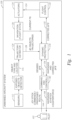
- Figure 1 illustrates an unmanned air vehicle system 100 to avoid collision by an air vehicle against objects on the ground, according to one aspect.
- a pilot 102 e.g., a human pilot
- the pilot 102 can initiate the flight for the air vehicle.
- the pilot 102 can do so by providing commands 104 to the unmanned air vehicle system, both to initiate the flight and to control the flight during operation.
- the commands 104 can include joystick commands, a predefined route for the air vehicle (e.g., within a particular airspace), or any other suitable command or commands.
- the air vehicle e.g., a UAV
- a command and control unit 140 can calculate variations to the current flight state (FS) for the air vehicle (e.g., altitude, velocity, course) for the UAV to follow the desired route, whether this is a predefined route or corresponds to ongoing commands from the pilot 102 (e.g., joystick commands).
- the command and control unit 140 provides a desired flight state ( ⁇ FS) 142 to a dynamic protection module 130.
- a ⁇ FS includes both a change to the flight state, and no-change to the flight state.
- the command and control unit 140 can repeatedly (e.g., continuously, at defined intervals, or using any other suitable technique) identify a ⁇ FS (e.g., continuation on a current flight plan or a modified flight plan).
- an exposed objects detector 114 identifies potentially exposed objects (e.g., on the ground or below the UAV).
- the exposed objects detector 114 can receive data from one or more sensors 112.
- the sensors 112 can include infrared sensors, radar sensors, LIDAR sensors, visible spectrum sensors (e.g., visible spectrum cameras), or any other suitable sensors.
- the exposed objects detector 114 uses suitable ML techniques to identify exposed objects.
- the exposed objects detector 114 can use a deep learning neural network (DNN) or another suitable ML technique (e.g., a supervised ML model) to identify objects using data from the sensors 112. This can include image object detection (e.g., from one or more visible spectrum cameras), or any other suitable ML technique.
- DNN deep learning neural network
- ML technique e.g., a supervised ML model
- image object detection e.g., from one or more visible spectrum cameras
- the use of ML is merely one example, and the exposed objects detector 114 can use any suitable technique or combination of
- the exposed objects detector 114 provides object type and location data 116 to a trajectory estimator.
- the trajectory estimator 120 estimates the four-dimensional (e.g., in three dimensions over time) trajectory of exposed objects detected at block 114.
- the trajectory estimator 120 can identify movement patterns for the objects.
- the exposed objects detector 114 uses suitable ML techniques to estimate the object trajectories. This is merely an example, and any suitable technique or combination of techniques known to those of ordinary skill in the art without undue experimentation can be used.
- the trajectory estimator 120 can compute dynamic sized safety buffers around the exposed objects identified at block 114.
- the trajectory estimator 120 can compute real-time safety buffer sizing requirements based on the characteristics of the object (e.g., the potential danger to the object, the movement speed of the object, the likelihood of movement by the object, and any other suitable characteristics) and the characteristics of the air vehicle (e.g., the UAV).
- the trajectory estimator 120 will compute a different dynamic safety buffer for a standing person, as compared to a person riding a bicycle or a fast-moving car, and the buffers will be dependent on the speed, size, mass and other suitable characteristics of the air vehicle.
- a flight control module 122 can operate actuators 124 in the air vehicle, to control the current FS, and a navigation module 126 can provide current FS information to the dynamic protection module 130.
- the dynamic protection module 130 uses any, or all, of the current FS data, the desired ⁇ FS 142, and estimated object trajectories 128 to compute whether the desired ⁇ FS 142 could lead to a risky situation (e.g., one where a collision between the air vehicle and an object is likely to occur) in the event of a hypothetical loss of propulsion.
- the dynamic protection module 130 can take a number of actions to protect against an unwanted collision occurring between the air vehicle and object. For example, the dynamic protection module 130 can provide warnings 134 to the command and control module 140, which can in turn provide warnings to the pilot 102 (e.g., joystick vibration, counterforces, or any other suitable warnings known to those of ordinary skill in the art without undue experimentation).
- the pilot 102 e.g., joystick vibration, counterforces, or any other suitable warnings known to those of ordinary skill in the art without undue experimentation.
- the dynamic protection module can automatically calculate a corrected ⁇ FS' 132 to reduce the collision risk.
- the dynamic protection module 130 can provide the corrected ⁇ FS' 132 to the command and control module 140 (e.g., along with any warnings 134). This can allow the pilot 102 to control the air vehicle to follow the suggested change in flight state indicated by the corrected ⁇ FS' 132.
- the dynamic protection module 130 can provide the corrected ⁇ FS' 132 to the flight control 122.
- the flight control 122 can control the actuators 124 (e.g., to change altitude, speed, course, or any other aspect) to modify the flight state.
- the actions taken by the dynamic protection module 130 when detecting a collision risk can be configured.
- a pilot 102, or any other suitable human operator could configure the unmanned air vehicle system 100 to provide desired behavior if a possible collision risk is detected.
- the dynamic protection module 130 can be configured to provide different responses (e.g., more, or less, aggressive flight state changes, preferring a change to one more particular aspects of flight state (e.g., altitude, speed, course) over other aspect(s), or any other suitable responses known to those of ordinary skill in the art without undue experimentation).
- different responses e.g., more, or less, aggressive flight state changes, preferring a change to one more particular aspects of flight state (e.g., altitude, speed, course) over other aspect(s), or any other suitable responses known to those of ordinary skill in the art without undue experimentation).
- FIG. 2 illustrates a block diagram of a controller 200 for controlling an unmanned air vehicle to avoid collision against objects on the ground, according to one aspect.
- the controller 200 includes a processor 202, a memory 210, and network components 220.
- the memory 210 may take the form of any non-transitory computer-readable medium known to those of ordinary skill in the art without undue experimentation.
- the processor 202 generally retrieves and executes programming instructions stored in the memory 210.
- the processor 202 is representative of a single central processing unit (CPU), multiple CPUs, a single CPU having multiple processing cores, graphics processing units (GPUs) having multiple execution paths, and the like.
- the network components 220 include the components necessary for controller 200 to interface with a suitable communication network.
- the network components 220 can include wired, WiFi, or cellular network interface components and associated software.
- the memory 210 is shown as a single entity, it will be understood by those of ordinary skill in the art without undue experimentation that the memory 210 may include one or more memory devices having blocks of memory associated with physical addresses, such as random access memory (RAM), read only memory (ROM), flash memory, or other types of volatile and/or non-volatile memory.
- RAM random access memory
- ROM read only memory
- flash memory or other types of volatile and/or non-volatile memory.
- the memory 210 generally includes program code for performing various functions related to use of the controller 200.
- the program code is generally described as various functional "applications" or “modules” within the memory 210, although, as will be understood by those of ordinary skill in the art without undue experimentation, alternate implementations may have different functions and/or combinations of functions.
- an object detector service 212 facilitates exposed object detection (e.g., as discussed above in relation to block 114 illustrated in Figure 1 and further below in relation to Figure 3 ).
- a trajectory estimator service 214 facilitates estimating exposed object trajectories (e.g., as discussed above in relation to block 120 illustrated in Figure 1 and further below in relation to Figure 3 ).
- a dynamic protection service 216 facilitates providing dynamic protection for objects below an air vehicle (e.g., objects on the ground below a UAV) in the event of a hypothetical loss of propulsion (e.g., as discussed above in relation to block 130 illustrated in Figure 1 and further below in relation to Figure 3 ).
- the controller 200 may include one or more computing platforms, such as computer servers for example, which may be co-located, or may form an interactively linked but distributed system, such as a cloud-based system (e.g., a public cloud, a private cloud, a hybrid cloud, or any other suitable cloud-based system).
- a cloud-based system e.g., a public cloud, a private cloud, a hybrid cloud, or any other suitable cloud-based system.
- the functionality of the object detector service 212, trajectory estimator service 214, and dynamic protection service 216 may be spread across an air vehicle, one or more ground control systems, and any other suitable computing systems.
- the processor 202 and the memory 210 may correspond to distributed processor and memory resources within one or more computing environments.
- the object detector service 212, trajectory estimator service 214, and dynamic protection service 216 may be stored remotely from the controller 200 within the distributed memory resources of one or more computing environments.
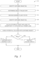
- Figure 3 is a flowchart 300 illustrating controlling an unmanned air vehicle to avoid collision against objects on the ground, according to one aspect.
- an object detector service e.g., the object detector service 212 illustrated in Figure 2
- the object detector service can use suitable ML techniques to identify objects beneath an air vehicle.
- the object detector service can detect static and moving objects using one or more on-board sensors, including but not limited to one or more cameras.
- the object detector service can detect and classify exposed objects based on purely visual data using one or more cameras on the visual spectrum.
- the object detector service can use additional information such as LIDAR point clouds, radar, data or infrared imaging sensors. These are merely examples.
- the object detection service can use ML for object detection and classification (e.g., a DNN or other suitable neural network or another trained ML model). This is also merely an example, and the object detection service can use any suitable technique (e.g., an algorithmic technique that does not use ML) known to those of ordinary skill in the art without undue experimentation.
- trajectory estimator service (e.g., the trajectory estimator service 214 illustrated in Figure 2 ) predicts trajectories for the one or more exposed objects. For example, as discussed above in relation to block 120 illustrated in Figure 1 , the trajectory estimator service can use suitable ML techniques to identify the trajectories of moving objects identified at block 302.
- the trajectory estimator service calculates the 4-dimenstional trajectory of these objects to predict their future position (e.g., using one or more suitable ML models). Further, the trajectory estimator service can use different techniques (e.g., different trained ML models) for different classifications of objects For example, different techniques could be used for walking pedestrians, cyclists, motorcyclists, automobiles, boats, or any other suitable moving objects.
- different techniques e.g., different trained ML models
- the trajectory estimator service uses a temporal data sequence (e.g., a video or LIDAR frame sequence) to track exposed objects, identify the status of exposed objects (e.g., static or moving), and predict the trajectory of any moving exposed objects.
- a temporal data sequence e.g., a video or LIDAR frame sequence
- Any suitable ML technique known to those of ordinary skill in the art without undue experimentation can be used.
- an ML model e.g., a DNN or other trained ML model
- multiple data sources e.g., data from multiple sensors or multiple types of sensor data
- the trajectory estimator service can use any suitable technique (e.g., any suitable ML technique or a non-ML technique) known to those of ordinary skill in the art without undue experimentation.
- a dynamic protection service receives a desired flight state.
- a pilot can provide ongoing commands (e.g., joystick commands), a pre-defined route, or both, to control an air vehicle (e.g., a UAV).
- the dynamic protection service can receive a desired flight state (e.g., a desired change to a current flight state or a desire to maintain flight conditions) reflecting these commands.
- the dynamic protection service identifies flight state.
- the dynamic protection service can receive a current flight state (e.g., attitude, altitude, speed, wind speed, latitude, longitude, bearing, etc.).
- the current flight state reflects any changes stemming from the corrected flight state.
- the current flight state can reflect changes after a corrected ⁇ FS' 132, illustrated in Figure 1 , is provided by the dynamic protection module 130 to the flight control unit 122.
- the dynamic protection service calculates a predicted collision point with any objects identified at block 302, and a level of uncertainty in the prediction, in the case of a hypothetical propulsion loss.
- the dynamic protection service can use the identified objects and trajectories (e.g., determined at blocks 302 and 304, above), the current flight state (e.g., received at block 308 above), and the desired flight state (e.g., received at block 306 above) to estimate when, or if, the air vehicle might collide with the exposed objects if the air vehicle were to lose propulsion.
- the dynamic protection service can use any, or all, of multiple different models to predict the collision point, including an uncontrolled gliding model for fixed wing air vehicle, a parabolic freefall model, an uncontrolled spin model, or any other suitable model known to those of ordinary skill in the art without undue experimentation.
- the dynamic protection service predicts collisions using all of these models.
- the dynamic protection service selects one or more preferred models (e.g., based on user commands, air vehicle characteristics, environmental characteristics, or any other suitable factors). Further, dynamic protection service can estimate the uncertainty of the prediction, based on the input values.
- the dynamic protection service can calculate a predicted collision point using the identified objects but without predicted trajectories for all objects (e.g., using predicted trajectories for some, or none, of the objects). This could reduce the accuracy of the predicted collision point, however, requiring a larger safety buffer for a corrected flight state (e.g., when protecting against collision at block 318, discussed below). That is, the use of predicted trajectories might not be required or suitable for all circumstances, but where available can increase the accuracy of the predicted collision point and reduce the necessary safety buffer to avoid a collision between the air vehicle and an object.
- the dynamic protection service checks for a potential collision with an exposed object. At block 314, if the dynamic protection service predicts a collision, the flow moves to block 318.
- the dynamic protection service protects against collisions. This is discussed further, below, with regard to Figure 5 .
- the dynamic protection service can provide a warning or other alert indicating a risk of collision to a pilot or other human operator.
- the dynamic protection service can automatically control the air vehicle to avoid a collision or reduce the likelihood of a collision occuring.
- the flow proceeds to block 316.
- the air vehicle continues with the desired flight (e.g., based on the desired flight state received at block 306).
- the air vehicle can move as instructed by the pilot (e.g., based on joystick control or use of a pre-defined route).
- the techniques illustrated in Figure 3 are performed continuously in real-time during flight.
- One or more controllers e.g., the controller 200 illustrated in Figure 2 ) continuously monitors for exposed objects and estimates trajectories.
- the dynamic protection service then identifies a risk of potential collision with the exposed objects, in the case of a hypothetical loss of propulsion, and protects against collisions.
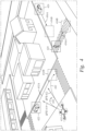
- Figure 4 illustrates an example of controlling an unmanned air vehicle to avoid collision against objects on the ground, according to one aspect.
- Figure 4 illustrates an example urban environment 400 in which an air vehicle (e.g., a UAV) 410 is operating. The air vehicle 410 is proceeding on a flight state 412, if no action is taken.
- An object detector service e.g., the object detector service 212 illustrated in Figure 2 ) identifies three potentially exposed objects: a car 422, a person 424, and another car 426.
- the object detector service can use a suitable ML model (e.g., a DNN) to detect these objects from one or more sensors associated with the air vehicle 410 (e.g., cameras, infra-red sensors, LIDAR, radar, or any other suitable sensors).
- the object detector service can further use the ML model to classify the objects (e.g., classify the car 422, the person 424, and the other car 426).
- a trajectory estimator service (e.g., the trajectory estimator service 214 illustrated in Figure 2 ) estimates the trajectories of each of the objects 422, 424, and 426. For example, the trajectory estimator service estimates the trajectory of the car 422 as the vector 432A leading to the location 432B. The trajectory estimator service estimates the trajectory of the person 424 as the vector 434A leading to the location 434B. The trajectory estimator service estimates the trajectory of the car other 426 as the vector 436A leading to the location 436B.
- a dynamic protection service determines whether the air vehicle 410 is at risk of colliding with any of the objects 422, 424, or 426, and takes steps to avoid a collision occurring. For example, the dynamic protection service calculates the estimated falling trajectory of the air vehicle 410 in the hypothetical event of a loss of propulsion as the curved dashed line 442.
- the dynamic protection service predicts that the air vehicle 410 is at risk of colliding with the car 422 if it suddenly loses propulsion, and in turn takes steps to avoid the collision occurring.
- the dynamic protection service can send commands to the air vehicle 410 (e.g., to actuators associated with the air vehicle 410) to change the flight state to a new flight state 414.
- a sudden loss of propulsion along the new flight state 414 would result in a different falling trajectory 444, in which the air vehicle 410 would not be at risk of colliding with the car 422 (or any other exposed object).
- the dynamic protection service can provide warnings to a pilot to encourage the pilot to change the flight state of the air vehicle 410.
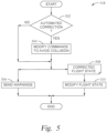
- Figure 5 is a flowchart illustrating protecting against collide by an unmanned air vehicle against objects on the ground, according to one aspect.
- Figure 5 corresponds with block 318 illustrated at Figure 3 .
- a dynamic protection service e.g., the dynamic protection service 216 illustrated in Figure 2 . determines whether to perform automated correction.
- the dynamic protection service can automatically correct a flight state of an air vehicle (e.g., a UAV) to avoid a risk of colliding with exposed objects, if a hypothetical loss of propulsion occurs.
- the dynamic protection service can determine a modified flight state for the air vehicle that reduces the risk of colliding, and can control the air vehicle (e.g., using suitable actuators) to travel on the modified flight state.
- the dynamic protection service can provide warnings to a human operator (e.g., a pilot) to control the air vehicle to reduce the risk of colliding.
- automated correction is configurable (e.g., by a human administrator). Alternatively, or in addition, automated correction depends on characteristics of the air vehicle, the flying environment, or any other suitable factors known to those of ordinary skill in the art without undue experimentation. For example, automated correction could be enabled for particular air vehicles, types of air vehicles, or flying environments, and disabled for other scenarios. If automated correction is available, the flow proceeds to block 504. If not, the flow proceeds to block 506, discussed further below.
- the dynamic protection service modifies commands to avoid collision.
- the dynamic protection service generates a corrected flight state 508.
- the corrected flight state 508 e.g., the corrected flight state 414 illustrated in Figure 4
- the corrected flight state 508 can reduce the risk of colliding with one or more exposed objects in case of a hypothetical loss of propulsion.
- the dynamic protection service can calculate a suitable safety buffer to reduce the risk of collision.
- the safety buffer can be based on characteristics of the air vehicle (e.g., speed, size, fall speed), the exposed objects, the environment (e.g., wind speed), and any other suitable characteristics known to those of ordinary skill in the art without undue experimentation.
- the safety buffer can be based on the certainty of the dynamic protection service's collision prediction. For example, as discussed above in relation to block 310 illustrated in Figure 3 , the dynamic protection service can calculate a level of certainty for its prediction of a collision point with an exposed object. This level of certainty can be used to generate a safety buffer for the corrected flight state 508. A higher level of certainty can require a smaller safety buffer, while a lower level of certainly can require a larger safety buffer. Further, as discussed above, use of object trajectories can reduce the required safety buffer.
- the dynamic protection service can use any, or all, of multiple different falling models to predict the fall trajectory of the air vehicle and generate the corrected flight states.
- the dynamic protection service can use one or more of an uncontrolled gliding model for fixed wing air vehicle, a parabolic freefall model, an uncontrolled spin model, or any other suitable model known to those of ordinary skill in the art without undue experimentation.
- the dynamic protection service selects one or more preferred models (e.g., based on user commands, air vehicle characteristics, environmental characteristics, or any other suitable factors known to those of ordinary skill in the art without undue experimentation).
- the dynamic protection service can calculate collision points on the ground upon applying different potential modifications to the corresponding flight parameters (e.g. speed, altitude, heading, etc.) in order to find a preferred non-collision trajectory based on (customer) predefined preferences (e.g., using an iterative process).
- the dynamic protection service modifies the flight state of the air vehicle.
- the dynamic protection service provides the corrected flight state 508 to one or more flight control modules (e.g., the flight control module 122 illustrated in Figure 1 ). This controls suitable actuators (e.g., the actuators 124 illustrated in Figure 1 ) to change the flight state of the air vehicle.
- the dynamic protection service proceeds to block 506 and sends one or more warnings to human operators relating to the potential collision with an exposed object.
- the dynamic protection service can send the warning(s) in addition to automatically modifying the air vehicle flight state, or instead of automatically modifying the air vehicle flight state (e.g., if automated correction is not available).
- the dynamic protection service can provide warnings or joystick counterforce to a pilot (e.g., warnings 144 illustrated in Figure 1 ). The pilot can then control the air vehicle to reduce the collision risk. Further, in an aspect, the dynamic protection service can provide the corrected flight state (e.g., in a human readable format) to the pilot to assist the pilot in controlling the air vehicle. The pilot can follow the corrected flight state (e.g., altitude, speed, direction) to reduce the risk of collision.
- a pilot e.g., warnings 144 illustrated in Figure 1
- the pilot can follow the corrected flight state (e.g., altitude, speed, direction) to reduce the risk of collision.
Landscapes
- Engineering & Computer Science (AREA)
- Remote Sensing (AREA)
- Aviation & Aerospace Engineering (AREA)
- Physics & Mathematics (AREA)
- General Physics & Mathematics (AREA)
- Theoretical Computer Science (AREA)
- Mechanical Engineering (AREA)
- Software Systems (AREA)
- Radar, Positioning & Navigation (AREA)
- Automation & Control Theory (AREA)
- Computing Systems (AREA)
- Medical Informatics (AREA)
- General Engineering & Computer Science (AREA)
- Artificial Intelligence (AREA)
- Mathematical Physics (AREA)
- Data Mining & Analysis (AREA)
- Computer Vision & Pattern Recognition (AREA)
- Evolutionary Computation (AREA)
- Microelectronics & Electronic Packaging (AREA)
- Control Of Position, Course, Altitude, Or Attitude Of Moving Bodies (AREA)
- Traffic Control Systems (AREA)
Abstract
Description
- Aspects of the present disclosure relate to vehicle control, and more specifically aspects of the invention relate to air vehicle (e.g., unmanned aerial vehicle (UAV)) control to avoid collision against objects on the ground in the case of air vehicle failure.
- Safety and risk assessment for UAVs, and other air vehicles, is critically important. To reduce this risk, governmental regulations in various jurisdictions require a UAV operator to undertake a risk assessment (e.g., a Specific Operations Risk Assessment (SORA)) for operation of the UAV. This can include a ground risk assessment that determines the risk to objects (e.g., any animate or inanimate object, including persons, animals, obstacles, structures, vehicles, and any other suitable objects) protruding from the ground, from operation of the UAV. For example, a loss of propulsion by the UAV could cause the air vehicle to lose control and fall to the ground, or otherwise impact (e.g., collide with) objects on the ground. In one aspect, a loss of propulsion can be caused by a loss of power, a loss of engine, an air collision, a projectile impact, or any other causational occurrence. One or more techniques described herein can be used to reduce the impact of potential UAV failure (e.g., loss of propulsion) on objects on the ground.
- Embodiments include a method. The method includes receiving a flight state for an air vehicle. The method further includes identifying an object below the air vehicle, using one or more sensors. The method further includes determining a risk that the air vehicle will collide with the object should the air vehicle later lose propulsion. The method further includes protecting against the air vehicle colliding with the object, based on the determined risk.
- Embodiments further include a non-transitory computer-readable medium containing computer program code that, when executed by operation of one or more computer processors, performs operations. The operations include receiving a flight state for an air vehicle. The operations further include identifying an object below the air vehicle, using one or more sensors. The operations further include determining a risk that the air vehicle will collide with the object should the air vehicle later lose propulsion. The operations further include protecting against the air vehicle colliding with the object, based on the determined risk.
- Embodiments further include an unmanned aerial vehicle (UAV), including a computer processor and a memory having instructions stored thereon which, when executed on the computer processor, performs operations. The operations include identifying a flight state for the UAV. The operations further include receiving a corrected flight state for the UAV, wherein the corrected flight state is calculated based on identifying an object below the UAV using one or more sensors and determining a risk that the UAV will collide with the object should the UAV later lose propulsion. The operations further include automatically controlling the UAV to operate using the corrected flight state.
- So that the manner in which the above recited features can be understood in detail, a more particular description, briefly summarized above, may be had by reference to example aspects, some of which are illustrated in the appended drawings.
-
Figure 1 illustrates an unmanned air vehicle system to avoid collision by an air vehicle against objects on the ground, according to one aspect. -
Figure 2 illustrates a block diagram of a controller for controlling an unmanned air vehicle to avoid collision against objects on the ground, according to one aspect. -
Figure 3 is a flowchart illustrating controlling an unmanned air vehicle to avoid collision against objects on the ground, according to one aspect. -
Figure 4 illustrates an example of controlling an unmanned air vehicle to avoid collision against objects on the ground, according to one aspect. -
Figure 5 is a flowchart illustrating protecting against collision by an unmanned air vehicle against objects on the ground, according to one aspect. - The present disclosure describes techniques to avoid an air vehicle (e.g., a UAV) impacting (e.g., colliding with) objects below the air vehicle (e.g., on the ground) in the event of a loss of propulsion. In an embodiment, objects can include any animate or inanimate object, including persons, animals, obstacles, structures, vehicles, and any other suitable objects. As discussed above, reducing ground risk from a UAV is extremely important. Existing solutions typically try to reduce ground risk by reducing the negative effect of a collision by the UAV with objects on the ground. For example, flight termination systems (FTSs), such as bulky parachutes or airbags, can be included in the UAV and used to slow the UAV in descent or reduce the force of a collision with objects on the ground. But these FTS add significant weight and drag to the UAV, greatly reducing its range (among other drawbacks).
- As another example, ground risk safety buffers can be used to limit the area of operation of the UAV, to effectively avoid critical ground objects.
- A ground risk safety buffer can be defined as an area around the operational area for the UAV that operates as the last area to contain a UAV that has exited both the operational and contingency areas. The UAV is expected to land within the boundaries of the ground risk safety buffer area (e.g., using an FTS to control landing). The size of this buffer is subject to the combination of hardware, software and procedural measures employed for the UAV. Generally speaking, the higher the robustness, the smaller the buffer required, and buffers are typically calculated manually (e.g., prior to operation of a UAV). But this significantly limits the area of operation for the UAV as density of population, and other factors, impacts the required ground risk safety buffer. Further, it can increase fuel and operating costs by changing UAV flight paths. For example, avoiding large safety buffers can require modified and inefficient flight paths that increase fuel and operating costs.
- Other existing solutions to reduce the effects of UAV failure focus on improving the reliability of UAVs, to avoid a loss of propulsion or other failure. For example, existing solutions may add redundancy to navigation or propulsion, to avoid UAV loss of propulsion. But this does not eliminate the risks to objects on the ground, in the event a loss of propulsion does indeed occur.
- One or more techniques described herein detect exposed objects below the air vehicle. For example, an a air vehicle, a ground station, or any other suitable control system can use artificial intelligence (Al) machine learning (ML) techniques to detect exposed objects and their trajectories on the ground, in real-time during the operation of the air vehicle. The control system can compute the potential falling trajectory of the air vehicle, also in real time. Accordingly, when the air vehicle is at risk of colliding with an exposed object on the ground, the control system can take steps to protect against the collision. For example, the control system can make changes to the air vehicle trajectory while the air vehicle is operating, to reduce any risk of collision in the case of a later, hypothetical, sudden loss of propulsion. Alternatively, or in addition, the control system can alert a pilot or other operator of the risk so that evasive action(s) can be taken. In this way the collision on the ground is contained to avoid exposed objects, without needing to equip the air vehicle with a bulky parachute or airbag and while reducing otherwise necessary safety buffers.
- One or more of these techniques have significant technical benefits. For example, the techniques greatly reduce the risk of an air vehicle crashing into objects upon loss of propulsion or other failure while still providing flexibility to the operator by reducing the size or necessary safety buffers. Further, one or more techniques can reduce pilot workload significantly by implementing corrections autonomously, and can eliminate the burden of mounting FTSs, such as bulky parachutes or airbags, in turn reducing weight and fuel required for the air vehicle.
- In the current disclosure, reference is made to various aspects. However, it should be understood that the present disclosure is not limited to specific described aspects. Instead, any combination of the following features and elements, whether related to different aspects or not, is contemplated to implement and practice the teachings provided herein. Additionally, when elements of the aspects are described in the form of "at least one of A and B," it will be understood that aspects including element A exclusively, including element B exclusively, and including element A and B are each contemplated. Furthermore, although some aspects may achieve advantages over other possible solutions and/or over the prior art, whether or not a particular advantage is achieved by a given aspect is not limiting of the present disclosure. Thus, the aspects, features, aspects, benefits and advantages disclosed herein are merely illustrative and are not considered elements or limitations of the appended claims except where explicitly recited in a claim(s). Likewise, reference to "the invention" shall not be construed as a generalization of any inventive subject matter disclosed herein and shall not be considered to be an element or limitation of the appended claims except where explicitly recited in a claim(s).
- As will be appreciated by one skilled in the art, aspects described herein may be embodied as a system, method or computer program product. Accordingly, aspects may take the form of an entirely hardware aspect, an entirely software aspect (including firmware, resident software, micro-code, etc.) or an aspect combining software and hardware aspects that may all generally be referred to herein as a "circuit," "module," "service," or "system." Furthermore, aspects described herein may take the form of a computer program product embodied in one or more computer readable storage medium(s) having computer readable program code embodied thereon.
- Program code embodied on a computer readable storage medium may be transmitted using any appropriate medium, including but not limited to wireless, wireline, optical fiber cable, RF, etc., or any suitable combination of the foregoing.
- Computer program code for carrying out operations for aspects of the present disclosure may be written in any combination of one or more programming languages, including an object-oriented programming language such as Java, Smalltalk, C++ or the like and conventional procedural programming languages, such as the "C" programming language or similar programming languages. The program code may execute entirely on the user's computer, partly on the user's computer, as a stand-alone software package, partly on the user's computer and partly on a remote computer or entirely on the remote computer or server. In the latter scenario, the remote computer may be connected to the user's computer through any type of network, including a local area network (LAN) or a wide area network (WAN), or the connection may be made to an external computer (for example, through the Internet using an Internet Service Provider).
- Aspects of the present disclosure are described herein with reference to flowchart illustrations and/or block diagrams of methods, apparatuses (systems), and computer program products according to aspects of the present disclosure. It will be understood that each block of the flowchart illustrations and/or block diagrams, and combinations of blocks in the flowchart illustrations and/or block diagrams, can be implemented by computer program instructions. These computer program instructions may be provided to a processor of a general purpose computer, special purpose computer, or other programmable data processing apparatus to produce a machine, such that the instructions, which execute via the processor of the computer or other programmable data processing apparatus, create means for implementing the functions/acts specified in the block(s) of the flowchart illustrations and/or block diagrams.
- These computer program instructions may also be stored in a computer readable medium that can direct a computer, other programmable data processing apparatus, or other device to function in a particular manner, such that the instructions stored in the computer readable medium produce an article of manufacture including instructions which implement the function/act specified in the block(s) of the flowchart illustrations and/or block diagrams.
- The computer program instructions may also be loaded onto a computer, other programmable data processing apparatus, or other device to cause a series of operational steps to be performed on the computer, other programmable apparatus or other device to produce a computer implemented process such that the instructions which execute on the computer, other programmable data processing apparatus, or other device provide processes for implementing the functions/acts specified in the block(s) of the flowchart illustrations and/or block diagrams.
- The flowchart illustrations and block diagrams in the Figures illustrate the architecture, functionality, and operation of possible implementations of systems, methods, and computer program products according to various aspects of the present disclosure. In this regard, each block in the flowchart illustrations or block diagrams may represent a module, segment, or portion of code, which comprises one or more executable instructions for implementing the specified logical function(s). It should also be noted that, in some alternative implementations, the functions noted in the block may occur out of the order noted in the Figures. For example, two blocks shown in succession may, in fact, be executed substantially concurrently, or the blocks may sometimes be executed in the reverse order or out of order, depending upon the functionality involved. It will also be noted that each block of the block diagrams and/or flowchart illustrations, and combinations of blocks in the block diagrams and/or flowchart illustrations, can be implemented by special purpose hardware-based systems that perform the specified functions or acts, or combinations of special purpose hardware and computer instructions.
- While the foregoing is directed to aspects of the present disclosure, other and further aspects of the disclosure may be devised without departing from the basic scope thereof, and the scope thereof is determined by the claims that follow.
-
Figure 1 illustrates an unmannedair vehicle system 100 to avoid collision by an air vehicle against objects on the ground, according to one aspect. Prior to starting a flight, a pilot 102 (e.g., a human pilot) can initiate the flight for the air vehicle. For example, thepilot 102 can do so by providingcommands 104 to the unmanned air vehicle system, both to initiate the flight and to control the flight during operation. Thecommands 104 can include joystick commands, a predefined route for the air vehicle (e.g., within a particular airspace), or any other suitable command or commands. - The air vehicle (e.g., a UAV) can then take off and begin operation. Once the UAV is in the air, a command and
control unit 140 can calculate variations to the current flight state (FS) for the air vehicle (e.g., altitude, velocity, course) for the UAV to follow the desired route, whether this is a predefined route or corresponds to ongoing commands from the pilot 102 (e.g., joystick commands). The command andcontrol unit 140 provides a desired flight state (ΔFS) 142 to adynamic protection module 130. In an embodiment, a ΔFS includes both a change to the flight state, and no-change to the flight state. For example, the command andcontrol unit 140 can repeatedly (e.g., continuously, at defined intervals, or using any other suitable technique) identify a ΔFS (e.g., continuation on a current flight plan or a modified flight plan). - In parallel, an exposed objects
detector 114 identifies potentially exposed objects (e.g., on the ground or below the UAV). For example, the exposedobjects detector 114 can receive data from one ormore sensors 112. Thesensors 112 can include infrared sensors, radar sensors, LIDAR sensors, visible spectrum sensors (e.g., visible spectrum cameras), or any other suitable sensors. In an aspect, as discussed further below, the exposedobjects detector 114 uses suitable ML techniques to identify exposed objects. For example, the exposedobjects detector 114 can use a deep learning neural network (DNN) or another suitable ML technique (e.g., a supervised ML model) to identify objects using data from thesensors 112. This can include image object detection (e.g., from one or more visible spectrum cameras), or any other suitable ML technique. The use of ML is merely one example, and the exposedobjects detector 114 can use any suitable technique or combination of techniques known to those of ordinary skill in the art without undue experimentation in order to identify exposed objects. - In one aspect, the exposed
objects detector 114 provides object type andlocation data 116 to a trajectory estimator. Thetrajectory estimator 120 estimates the four-dimensional (e.g., in three dimensions over time) trajectory of exposed objects detected atblock 114. For example, thetrajectory estimator 120 can identify movement patterns for the objects. In one aspect, the exposedobjects detector 114 uses suitable ML techniques to estimate the object trajectories. This is merely an example, and any suitable technique or combination of techniques known to those of ordinary skill in the art without undue experimentation can be used. - Alternatively, or in addition, the trajectory estimator 120 (or any other suitable module) can compute dynamic sized safety buffers around the exposed objects identified at
block 114. For example thetrajectory estimator 120 can compute real-time safety buffer sizing requirements based on the characteristics of the object (e.g., the potential danger to the object, the movement speed of the object, the likelihood of movement by the object, and any other suitable characteristics) and the characteristics of the air vehicle (e.g., the UAV). For example, thetrajectory estimator 120 will compute a different dynamic safety buffer for a standing person, as compared to a person riding a bicycle or a fast-moving car, and the buffers will be dependent on the speed, size, mass and other suitable characteristics of the air vehicle. - In an aspect, a
flight control module 122 can operateactuators 124 in the air vehicle, to control the current FS, and anavigation module 126 can provide current FS information to thedynamic protection module 130. Thedynamic protection module 130 uses any, or all, of the current FS data, the desiredΔFS 142, and estimatedobject trajectories 128 to compute whether the desiredΔFS 142 could lead to a risky situation (e.g., one where a collision between the air vehicle and an object is likely to occur) in the event of a hypothetical loss of propulsion. - If such collision risk is detected, the
dynamic protection module 130 can take a number of actions to protect against an unwanted collision occurring between the air vehicle and object. For example, thedynamic protection module 130 can providewarnings 134 to the command andcontrol module 140, which can in turn provide warnings to the pilot 102 (e.g., joystick vibration, counterforces, or any other suitable warnings known to those of ordinary skill in the art without undue experimentation). - Alternatively, or in addition, the dynamic protection module can automatically calculate a corrected ΔFS' 132 to reduce the collision risk. The
dynamic protection module 130 can provide the corrected ΔFS' 132 to the command and control module 140 (e.g., along with any warnings 134). This can allow thepilot 102 to control the air vehicle to follow the suggested change in flight state indicated by the corrected ΔFS' 132. - Further, the
dynamic protection module 130 can provide the corrected ΔFS' 132 to theflight control 122. Theflight control 122 can control the actuators 124 (e.g., to change altitude, speed, course, or any other aspect) to modify the flight state. In an aspect, the actions taken by thedynamic protection module 130 when detecting a collision risk (e.g., whether to provide any, or all, of warnings, a recommended flight state change, or automated flight state change) can be configured. For example, apilot 102, or any other suitable human operator, could configure the unmannedair vehicle system 100 to provide desired behavior if a possible collision risk is detected. Further, thedynamic protection module 130 can be configured to provide different responses (e.g., more, or less, aggressive flight state changes, preferring a change to one more particular aspects of flight state (e.g., altitude, speed, course) over other aspect(s), or any other suitable responses known to those of ordinary skill in the art without undue experimentation). -
Figure 2 illustrates a block diagram of acontroller 200 for controlling an unmanned air vehicle to avoid collision against objects on the ground, according to one aspect. In an aspect, thecontroller 200 includes aprocessor 202, amemory 210, andnetwork components 220. Thememory 210 may take the form of any non-transitory computer-readable medium known to those of ordinary skill in the art without undue experimentation. Theprocessor 202 generally retrieves and executes programming instructions stored in thememory 210. Theprocessor 202 is representative of a single central processing unit (CPU), multiple CPUs, a single CPU having multiple processing cores, graphics processing units (GPUs) having multiple execution paths, and the like. - The
network components 220 include the components necessary forcontroller 200 to interface with a suitable communication network. For example, thenetwork components 220 can include wired, WiFi, or cellular network interface components and associated software. Although thememory 210 is shown as a single entity, it will be understood by those of ordinary skill in the art without undue experimentation that thememory 210 may include one or more memory devices having blocks of memory associated with physical addresses, such as random access memory (RAM), read only memory (ROM), flash memory, or other types of volatile and/or non-volatile memory. - The
memory 210 generally includes program code for performing various functions related to use of thecontroller 200. The program code is generally described as various functional "applications" or "modules" within thememory 210, although, as will be understood by those of ordinary skill in the art without undue experimentation, alternate implementations may have different functions and/or combinations of functions. Within thememory 210, anobject detector service 212 facilitates exposed object detection (e.g., as discussed above in relation to block 114 illustrated inFigure 1 and further below in relation toFigure 3 ). Atrajectory estimator service 214 facilitates estimating exposed object trajectories (e.g., as discussed above in relation to block 120 illustrated inFigure 1 and further below in relation toFigure 3 ). Adynamic protection service 216 facilitates providing dynamic protection for objects below an air vehicle (e.g., objects on the ground below a UAV) in the event of a hypothetical loss of propulsion (e.g., as discussed above in relation to block 130 illustrated inFigure 1 and further below in relation toFigure 3 ). - Although
Figure 2 depicts theobject detector service 212,trajectory estimator service 214, anddynamic protection service 216, as located in thememory 210, that representation is merely provided as an illustration for clarity. More generally, thecontroller 200 may include one or more computing platforms, such as computer servers for example, which may be co-located, or may form an interactively linked but distributed system, such as a cloud-based system (e.g., a public cloud, a private cloud, a hybrid cloud, or any other suitable cloud-based system). For example, the functionality of theobject detector service 212,trajectory estimator service 214, anddynamic protection service 216 may be spread across an air vehicle, one or more ground control systems, and any other suitable computing systems. As a result, theprocessor 202 and thememory 210 may correspond to distributed processor and memory resources within one or more computing environments. Thus, it is to be understood by those of ordinary skill in the art without undue experimentation that any, or all, of theobject detector service 212,trajectory estimator service 214, anddynamic protection service 216 may be stored remotely from thecontroller 200 within the distributed memory resources of one or more computing environments. -
Figure 3 is a flowchart 300 illustrating controlling an unmanned air vehicle to avoid collision against objects on the ground, according to one aspect. At block 302 an object detector service (e.g., theobject detector service 212 illustrated inFigure 2 ) identifies one or more exposed objects. For example, as discussed above in relation to block 114 illustrated inFigure 1 , the object detector service can use suitable ML techniques to identify objects beneath an air vehicle. - In an aspect, the object detector service can detect static and moving objects using one or more on-board sensors, including but not limited to one or more cameras. The object detector service can detect and classify exposed objects based on purely visual data using one or more cameras on the visual spectrum. Alternatively, or in addition, the object detector service can use additional information such as LIDAR point clouds, radar, data or infrared imaging sensors. These are merely examples. Further, the object detection service can use ML for object detection and classification (e.g., a DNN or other suitable neural network or another trained ML model). This is also merely an example, and the object detection service can use any suitable technique (e.g., an algorithmic technique that does not use ML) known to those of ordinary skill in the art without undue experimentation.
- At
block 304, trajectory estimator service (e.g., thetrajectory estimator service 214 illustrated inFigure 2 ) predicts trajectories for the one or more exposed objects. For example, as discussed above in relation to block 120 illustrated inFigure 1 , the trajectory estimator service can use suitable ML techniques to identify the trajectories of moving objects identified at block 302. - In an aspect, the trajectory estimator service calculates the 4-dimenstional trajectory of these objects to predict their future position (e.g., using one or more suitable ML models). Further, the trajectory estimator service can use different techniques (e.g., different trained ML models) for different classifications of objects For example, different techniques could be used for walking pedestrians, cyclists, motorcyclists, automobiles, boats, or any other suitable moving objects.
- In an aspect, the trajectory estimator service uses a temporal data sequence (e.g., a video or LIDAR frame sequence) to track exposed objects, identify the status of exposed objects (e.g., static or moving), and predict the trajectory of any moving exposed objects. Any suitable ML technique known to those of ordinary skill in the art without undue experimentation can be used. For example, an ML model (e.g., a DNN or other trained ML model) can be trained to take a sequence of data frames for each one of the detected objects and infer a prediction of the future trajectory of the objects. In an aspect, multiple data sources (e.g., data from multiple sensors or multiple types of sensor data) can be used enhance the accuracy of the prediction. This is merely an example, however, and the trajectory estimator service can use any suitable technique (e.g., any suitable ML technique or a non-ML technique) known to those of ordinary skill in the art without undue experimentation.
- At
block 306, a dynamic protection service (e.g., thedynamic protection service 216 illustrated inFigure 2 ) receives a desired flight state. For example, as discussed above in relation to block 142 illustrated inFigure 1 , a pilot can provide ongoing commands (e.g., joystick commands), a pre-defined route, or both, to control an air vehicle (e.g., a UAV). The dynamic protection service can receive a desired flight state (e.g., a desired change to a current flight state or a desire to maintain flight conditions) reflecting these commands. - At
block 308, the dynamic protection service identifies flight state. For example, as discussed above in relation to block 126 illustrated inFigure 1 , the dynamic protection service can receive a current flight state (e.g., attitude, altitude, speed, wind speed, latitude, longitude, bearing, etc.). In an embodiment, the current flight state reflects any changes stemming from the corrected flight state. For example, the current flight state can reflect changes after a corrected ΔFS' 132, illustrated inFigure 1 , is provided by thedynamic protection module 130 to theflight control unit 122. - At
block 310, the dynamic protection service calculates a predicted collision point with any objects identified at block 302, and a level of uncertainty in the prediction, in the case of a hypothetical propulsion loss. For example, the dynamic protection service can use the identified objects and trajectories (e.g., determined atblocks 302 and 304, above), the current flight state (e.g., received atblock 308 above), and the desired flight state (e.g., received atblock 306 above) to estimate when, or if, the air vehicle might collide with the exposed objects if the air vehicle were to lose propulsion. - In an aspect, the dynamic protection service can use any, or all, of multiple different models to predict the collision point, including an uncontrolled gliding model for fixed wing air vehicle, a parabolic freefall model, an uncontrolled spin model, or any other suitable model known to those of ordinary skill in the art without undue experimentation. In one aspect, the dynamic protection service predicts collisions using all of these models. Alternatively, the dynamic protection service selects one or more preferred models (e.g., based on user commands, air vehicle characteristics, environmental characteristics, or any other suitable factors). Further, dynamic protection service can estimate the uncertainty of the prediction, based on the input values.
- Further, in an embodiment, the dynamic protection service can calculate a predicted collision point using the identified objects but without predicted trajectories for all objects (e.g., using predicted trajectories for some, or none, of the objects). This could reduce the accuracy of the predicted collision point, however, requiring a larger safety buffer for a corrected flight state (e.g., when protecting against collision at
block 318, discussed below). That is, the use of predicted trajectories might not be required or suitable for all circumstances, but where available can increase the accuracy of the predicted collision point and reduce the necessary safety buffer to avoid a collision between the air vehicle and an object. - At
block 312, the dynamic protection service checks for a potential collision with an exposed object. Atblock 314, if the dynamic protection service predicts a collision, the flow moves to block 318. - At
block 318, the dynamic protection service protects against collisions. This is discussed further, below, with regard toFigure 5 . For example, the dynamic protection service can provide a warning or other alert indicating a risk of collision to a pilot or other human operator. Alternatively, or in addition, the dynamic protection service can automatically control the air vehicle to avoid a collision or reduce the likelihood of a collision occuring. - Returning to block 314, if the dynamic protection service predicts no collision with any exposed objects, the flow proceeds to block 316. At
block 316 the air vehicle continues with the desired flight (e.g., based on the desired flight state received at block 306). For example, the air vehicle can move as instructed by the pilot (e.g., based on joystick control or use of a pre-defined route). - In an embodiment, the techniques illustrated in
Figure 3 are performed continuously in real-time during flight. One or more controllers (e.g., thecontroller 200 illustrated inFigure 2 ) continuously monitors for exposed objects and estimates trajectories. The dynamic protection service then identifies a risk of potential collision with the exposed objects, in the case of a hypothetical loss of propulsion, and protects against collisions. -
Figure 4 illustrates an example of controlling an unmanned air vehicle to avoid collision against objects on the ground, according to one aspect.Figure 4 illustrates an example urban environment 400 in which an air vehicle (e.g., a UAV) 410 is operating. Theair vehicle 410 is proceeding on a flight state 412, if no action is taken. An object detector service (e.g., theobject detector service 212 illustrated inFigure 2 ) identifies three potentially exposed objects: acar 422, aperson 424, and another car 426. For example, the object detector service can use a suitable ML model (e.g., a DNN) to detect these objects from one or more sensors associated with the air vehicle 410 (e.g., cameras, infra-red sensors, LIDAR, radar, or any other suitable sensors). The object detector service can further use the ML model to classify the objects (e.g., classify thecar 422, theperson 424, and the other car 426). - In an aspect, a trajectory estimator service (e.g., the
trajectory estimator service 214 illustrated inFigure 2 ) estimates the trajectories of each of theobjects car 422 as thevector 432A leading to thelocation 432B. The trajectory estimator service estimates the trajectory of theperson 424 as thevector 434A leading to thelocation 434B. The trajectory estimator service estimates the trajectory of the car other 426 as thevector 436A leading to thelocation 436B. - In an aspect, a dynamic protection service (e.g., the
dynamic protection service 216 illustrated inFigure 2 ) determines whether theair vehicle 410 is at risk of colliding with any of theobjects air vehicle 410 in the hypothetical event of a loss of propulsion as the curved dashedline 442. - The dynamic protection service predicts that the
air vehicle 410 is at risk of colliding with thecar 422 if it suddenly loses propulsion, and in turn takes steps to avoid the collision occurring. For example, the dynamic protection service can send commands to the air vehicle 410 (e.g., to actuators associated with the air vehicle 410) to change the flight state to anew flight state 414. A sudden loss of propulsion along thenew flight state 414 would result in a different fallingtrajectory 444, in which theair vehicle 410 would not be at risk of colliding with the car 422 (or any other exposed object). Alternatively, or in addition, the dynamic protection service can provide warnings to a pilot to encourage the pilot to change the flight state of theair vehicle 410. The illustration inFigure 4 is merely one example, and, as would be known to those of ordinary skill in the art without undue experimentation, one or more techniques described herein can be applied for a variety of air vehicles (e.g., a variety of manned or unmanned flying vehicles) in a variety of environments. -
Figure 5 is a flowchart illustrating protecting against collide by an unmanned air vehicle against objects on the ground, according to one aspect. In an aspect,Figure 5 corresponds withblock 318 illustrated atFigure 3 . Atblock 502, a dynamic protection service (e.g., thedynamic protection service 216 illustrated inFigure 2 ) determines whether to perform automated correction. - As discussed above, in one aspect the dynamic protection service can automatically correct a flight state of an air vehicle (e.g., a UAV) to avoid a risk of colliding with exposed objects, if a hypothetical loss of propulsion occurs. For example, the dynamic protection service can determine a modified flight state for the air vehicle that reduces the risk of colliding, and can control the air vehicle (e.g., using suitable actuators) to travel on the modified flight state. Alternatively, or in addition, the dynamic protection service can provide warnings to a human operator (e.g., a pilot) to control the air vehicle to reduce the risk of colliding.
- In an aspect, automated correction is configurable (e.g., by a human administrator). Alternatively, or in addition, automated correction depends on characteristics of the air vehicle, the flying environment, or any other suitable factors known to those of ordinary skill in the art without undue experimentation. For example, automated correction could be enabled for particular air vehicles, types of air vehicles, or flying environments, and disabled for other scenarios. If automated correction is available, the flow proceeds to block 504. If not, the flow proceeds to block 506, discussed further below.
- At
block 504, the dynamic protection service modifies commands to avoid collision. In an aspect, the dynamic protection service generates a correctedflight state 508. For example, as illustrated inFigure 4 , above, the corrected flight state 508 (e.g., the correctedflight state 414 illustrated inFigure 4 ) can reduce the risk of colliding with one or more exposed objects in case of a hypothetical loss of propulsion. - In an aspect, the dynamic protection service can calculate a suitable safety buffer to reduce the risk of collision. The safety buffer can be based on characteristics of the air vehicle (e.g., speed, size, fall speed), the exposed objects, the environment (e.g., wind speed), and any other suitable characteristics known to those of ordinary skill in the art without undue experimentation. Further, the safety buffer can be based on the certainty of the dynamic protection service's collision prediction. For example, as discussed above in relation to block 310 illustrated in
Figure 3 , the dynamic protection service can calculate a level of certainty for its prediction of a collision point with an exposed object. This level of certainty can be used to generate a safety buffer for the correctedflight state 508. A higher level of certainty can require a smaller safety buffer, while a lower level of certainly can require a larger safety buffer. Further, as discussed above, use of object trajectories can reduce the required safety buffer. - Further, the dynamic protection service can use any, or all, of multiple different falling models to predict the fall trajectory of the air vehicle and generate the corrected flight states. The dynamic protection service can use one or more of an uncontrolled gliding model for fixed wing air vehicle, a parabolic freefall model, an uncontrolled spin model, or any other suitable model known to those of ordinary skill in the art without undue experimentation. In an embodiment, the dynamic protection service selects one or more preferred models (e.g., based on user commands, air vehicle characteristics, environmental characteristics, or any other suitable factors known to those of ordinary skill in the art without undue experimentation). Further, the dynamic protection service can calculate collision points on the ground upon applying different potential modifications to the corresponding flight parameters (e.g. speed, altitude, heading, etc.) in order to find a preferred non-collision trajectory based on (customer) predefined preferences (e.g., using an iterative process).
- At block 510, the dynamic protection service modifies the flight state of the air vehicle. In an aspect, the dynamic protection service provides the corrected
flight state 508 to one or more flight control modules (e.g., theflight control module 122 illustrated inFigure 1 ). This controls suitable actuators (e.g., theactuators 124 illustrated inFigure 1 ) to change the flight state of the air vehicle. - Returning to block 504, in an aspect the dynamic protection service proceeds to block 506 and sends one or more warnings to human operators relating to the potential collision with an exposed object. The dynamic protection service can send the warning(s) in addition to automatically modifying the air vehicle flight state, or instead of automatically modifying the air vehicle flight state (e.g., if automated correction is not available).
- At
block 506 the dynamic protection service can provide warnings or joystick counterforce to a pilot (e.g.,warnings 144 illustrated inFigure 1 ). The pilot can then control the air vehicle to reduce the collision risk. Further, in an aspect, the dynamic protection service can provide the corrected flight state (e.g., in a human readable format) to the pilot to assist the pilot in controlling the air vehicle. The pilot can follow the corrected flight state (e.g., altitude, speed, direction) to reduce the risk of collision. - Further, the current disclosure comprises embodiments according to the following clauses:
- Clause 1. A method, comprising:
- receiving a flight state for an air vehicle;
- identifying an object below the air vehicle, using one or more sensors;
- determining a risk that the air vehicle will collide with the object should the air vehicle later lose propulsion; and
- protecting against the air vehicle colliding with the object, based on the determined risk.
- Clause 2. The method of clause 1, wherein the air vehicle comprises an unmanned aerial vehicle (UAV), the method further comprising:
determining a predicted trajectory for the object, wherein determining the risk that the UAV will collide with the object is further based, at least in part, on the predicted trajectory. - Clause 3. The method of clause 2, wherein identifying the object uses a first one or more trained machine learning (ML) models and determining the predicted trajectory uses a second one or more trained ML models.
- Clause 4. The method of clause 3, wherein the first and second one or more trained ML models each comprise respective deep learning neural networks (DNNs).
- Clause 5. The method of any of clauses 1 to 4, wherein the one or more sensors comprise at least one of: (i) a visual spectrum camera, (ii) an infra-red sensor, (iii) LIDAR, or (iv) radar.
- Clause 6. The method of any of clauses 1 to 5, wherein determining the risk that the air vehicle will collide with the object should the air vehicle later lose propulsion comprises using a falling model for the air vehicle.
- Clause 7. The method of clause 6, wherein the falling model comprises at least one of: (i) an uncontrolled gliding model for fixed wing air vehicle, (ii) a parabolic freefall model, or (iii) an uncontrolled spin model.
- Clause 8. The method of any of clauses 1 to 7, wherein protecting against the air vehicle colliding with the object comprises:
- generating a corrected flight state for the air vehicle; and
- automatically controlling the air vehicle to operate using the corrected flight state.
- Clause 9. The method of clause 8, wherein generating the corrected flight state for the air vehicle further comprises:
generating a safety buffer for the air vehicle and the object, wherein the corrected flight state is based on the safety buffer. -
Clause 10. The method of any of clauses 1 to 9, wherein protecting against the air vehicle colliding with the object comprises:
transmitting a warning to a pilot for the air vehicle reflecting the risk that the air vehicle will collide with the object should the air vehicle later lose propulsion. - Clause 11. The method of
clause 10, wherein protecting against the air vehicle colliding with the object further comprises:- generating a corrected flight state for the air vehicle; and
- providing at least a portion of the corrected flight state to the pilot.
- Clause 12. A non-transitory computer-readable medium containing computer program code that, when executed by operation of one or more computer processors, performs operations comprising:
- receiving a flight state for an air vehicle;
- identifying an object below the air vehicle, using one or more sensors;
- determining a risk that the air vehicle will collide with the object should the air vehicle later lose propulsion; and
- protecting against the air vehicle colliding with the object, based on the determined risk.
- Clause 13. The non-transitory computer-readable medium of clause 12, wherein the air vehicle comprises an unmanned aerial vehicle (UAV), the operations further comprising:
determining a predicted trajectory for the object, wherein determining the risk that the UAV will collide with the object is further based on the predicted trajectory, wherein identifying the object uses a first one or more trained machine learning (ML) models and determining the predicted trajectory uses a second one or more trained ML models. - Clause 14. The non-transitory computer-readable medium of clause 12 or 13, wherein determining the risk that the air vehicle will collide with the object should the UAV later lose propulsion comprises using a falling model for the air vehicle.
- Clause 15. The non-transitory computer-readable medium of any of clauses 12 to 14, wherein protecting against the air vehicle colliding with the object comprises:
- generating a corrected flight state for the air vehicle; and
- automatically controlling the air vehicle to operate using the corrected flight state.
- Clause 16. An unmanned aerial vehicle (UAV), comprising:
- a computer processor; and
- a memory having instructions stored thereon which, when executed on the computer processor, performs operations comprising:
- identifying a flight state for the UAV;
- receiving a corrected flight state for the UAV, wherein the corrected flight state is calculated based on identifying an object below the UAV using one or more sensors and determining a risk that the UAV will collide with the object should the UAV later lose propulsion; and
- automatically controlling the UAV to operate using the corrected flight state.
- Clause 17. The UAV of clause 16, wherein the corrected flight state is further based, at least in part, on determining a predicted trajectory for the object and wherein identifying the object uses a first one or more trained machine learning (ML) models and determining the predicted trajectory uses a second one or more trained ML models.
- Clause 18. The UAV of clause 16 or 17, wherein determining the risk that the UAV will collide with the object should the UAV later lose propulsion comprises using a falling model for the UAV.
- Clause 19. The UAV of any of clauses 16 to 18, wherein the UAV comprises the one or more sensors, the operations further comprising:
capturing sensor data relating to the object using the one or more sensors. - Clause 20. The UAV of clause 19, wherein the one or more sensors comprise at least one of: (i) a visual spectrum camera, (ii) an infra-red sensor, (iii) LIDAR, or (iv) radar.
Claims (15)
- A method, comprising:receiving a flight state for an air vehicle (306);identifying an object below the air vehicle, using one or more sensors (302);determining a risk that the air vehicle will collide with the object should the air vehicle later lose propulsion (310); andprotecting against the air vehicle colliding with the object, based on the determined risk (318).
- The method of claim 1, wherein the air vehicle comprises an unmanned aerial vehicle (UAV) (100, 410), the method further comprising:
determining a predicted trajectory for the object (304, 432A, 434A, 436A),
wherein determining the risk that the UAV will collide with the object is further based, at least in part, on the predicted trajectory (310). - The method of claim 2, wherein identifying the object uses a first one or more trained machine learning (ML) models (302) and determining the predicted trajectory uses a second one or more trained ML models (304).
- The method of claim 3, wherein the first and second one or more trained ML models each comprise respective deep learning neural networks (DNNs) (302, 304).
- The method of any of claims 1 to 4, wherein the one or more sensors (112) comprise at least one of: (i) a visual spectrum camera, (ii) an infra-red sensor, (iii) LIDAR, or (iv) radar.
- The method of any of claims 1 to 5, wherein determining the risk that the air vehicle will collide with the object should the air vehicle later lose propulsion comprises using a falling model for the air vehicle (310).
- The method of claim 6, wherein the falling model (310) comprises at least one of: (i) an uncontrolled gliding model for fixed wing air vehicle, (ii) a parabolic freefall model, or (iii) an uncontrolled spin model.
- The method of any of claims 1 to 7, wherein protecting against the air vehicle colliding with the object comprises:generating a corrected flight state for the air vehicle (508); andautomatically controlling the air vehicle to operate using the corrected flight state (510).
- The method of claim 8, wherein generating the corrected flight state for the air vehicle further comprises:
generating a safety buffer for the air vehicle and the object, wherein the corrected flight state is based on the safety buffer (508). - The method of any of claims 1 to 9, wherein protecting against the air vehicle colliding with the object comprises:
transmitting a warning to a pilot for the air vehicle reflecting the risk that the air vehicle will collide with the object should the air vehicle later lose propulsion (506). - The method of claim 10, wherein protecting against the air vehicle colliding with the object further comprises:generating a corrected flight state for the air vehicle (508); andproviding at least a portion of the corrected flight state to the pilot (506, 508).
- A non-transitory computer-readable medium containing computer program code that, when executed by operation of one or more computer processors, performs operations comprising:receiving a flight state for an air vehicle (306);identifying an object below the air vehicle, using one or more sensors (302);determining a risk that the air vehicle will collide with the object should the air vehicle later lose propulsion (310); andprotecting against the air vehicle colliding with the object, based on the determined risk (318).
- The non-transitory computer-readable medium of claim 12, wherein the air vehicle comprises an unmanned aerial vehicle (UAV) (100, 410), the operations further comprising:
determining a predicted trajectory for the object (304, 432A, 434A, 436A),
wherein determining the risk that the UAV will collide with the object is further based on the predicted trajectory (310), wherein identifying the object uses a first one or more trained machine learning (ML) models (302) and determining the predicted trajectory uses a second one or more trained ML models (304), in particular wherein determining the risk that the air vehicle will collide with the object should the UAV later lose propulsion comprises using a falling model for the air vehicle (310). - The non-transitory computer-readable medium of claim 12 or 13, wherein protecting against the air vehicle colliding with the object comprises:generating a corrected flight state for the air vehicle (508); andautomatically controlling the air vehicle to operate using the corrected flight state (510).
- An unmanned aerial vehicle (UAV), comprising:a computer processor (202); anda memory (210) having instructions stored thereon which, when executed on the computer processor, performs operations comprising:identifying a flight state for the UAV (306);receiving a corrected flight state for the UAV (508), wherein the corrected flight state is calculated based on identifying an object below the UAV using one or more sensors (110) and determining a risk that the UAV will collide with the object should the UAV later lose propulsion (310); andautomatically controlling the UAV to operate using the corrected flight state (510).
Applications Claiming Priority (1)
| Application Number | Priority Date | Filing Date | Title |
|---|---|---|---|
| US18/338,274 US20240425211A1 (en) | 2023-06-20 | 2023-06-20 | Air vehicle control to avoid collision against objects on ground upon potential failure |
Publications (2)
| Publication Number | Publication Date |
|---|---|
| EP4481530A1 true EP4481530A1 (en) | 2024-12-25 |
| EP4481530B1 EP4481530B1 (en) | 2025-11-19 |
Family
ID=90482545
Family Applications (1)
| Application Number | Title | Priority Date | Filing Date |
|---|---|---|---|
| EP24166963.9A Active EP4481530B1 (en) | 2023-06-20 | 2024-03-27 | Air vehicle control to avoid collision against objects upon potential failure |
Country Status (3)
| Country | Link |
|---|---|
| US (1) | US20240425211A1 (en) |
| EP (1) | EP4481530B1 (en) |
| CN (1) | CN119169879A (en) |
Families Citing this family (2)
| Publication number | Priority date | Publication date | Assignee | Title |
|---|---|---|---|---|
| US12691905B2 (en) | 2023-07-13 | 2026-07-28 | Torc Robotics, Inc. | Methods and systems for learning safe driving paths |
| US20250018981A1 (en) * | 2023-07-13 | 2025-01-16 | Torc Robotics, Inc. | Methods and systems for learning safe driving paths |
Citations (3)
| Publication number | Priority date | Publication date | Assignee | Title |
|---|---|---|---|---|
| US20180022310A1 (en) * | 2016-03-24 | 2018-01-25 | Rhombus Systems Group, Inc. | Airbag system for use with unmanned aerial vehicles |
| US20210295554A1 (en) * | 2018-09-04 | 2021-09-23 | Sony Corporation | Information processing device, information processing method, program, and mobile device |
| CN214397257U (en) * | 2020-12-24 | 2021-10-15 | 安徽梧桐航空科技有限公司 | Use parachuting protection device on unmanned aerial vehicle |
Family Cites Families (2)
| Publication number | Priority date | Publication date | Assignee | Title |
|---|---|---|---|---|
| JP6278539B2 (en) * | 2014-09-05 | 2018-02-14 | エスゼット ディージェイアイ テクノロジー カンパニー リミテッドSz Dji Technology Co.,Ltd | Flight mode selection based on situation |
| US20160196754A1 (en) * | 2015-01-06 | 2016-07-07 | Honeywell International Inc. | Airport surface monitoring system with wireless network interface to aircraft surface navigation system |
-
2023
- 2023-06-20 US US18/338,274 patent/US20240425211A1/en active Pending
-
2024
- 2024-03-27 EP EP24166963.9A patent/EP4481530B1/en active Active
- 2024-06-14 CN CN202410766011.4A patent/CN119169879A/en active Pending
Patent Citations (3)
| Publication number | Priority date | Publication date | Assignee | Title |
|---|---|---|---|---|
| US20180022310A1 (en) * | 2016-03-24 | 2018-01-25 | Rhombus Systems Group, Inc. | Airbag system for use with unmanned aerial vehicles |
| US20210295554A1 (en) * | 2018-09-04 | 2021-09-23 | Sony Corporation | Information processing device, information processing method, program, and mobile device |
| CN214397257U (en) * | 2020-12-24 | 2021-10-15 | 安徽梧桐航空科技有限公司 | Use parachuting protection device on unmanned aerial vehicle |
Also Published As
| Publication number | Publication date |
|---|---|
| EP4481530B1 (en) | 2025-11-19 |
| CN119169879A (en) | 2024-12-20 |
| US20240425211A1 (en) | 2024-12-26 |
Similar Documents
| Publication | Publication Date | Title |
|---|---|---|
| US11249494B2 (en) | Systems and methods for sensing and avoiding external objects for aircraft | |
| JP7666679B2 (en) | Aircraft control device, aircraft control method, and program | |
| EP4481530B1 (en) | Air vehicle control to avoid collision against objects upon potential failure | |
| US20250388231A1 (en) | Method and system for feasibility-based operation of an autonomous agent | |
| US20200217967A1 (en) | Systems and methods for modulating the range of a lidar sensor on an aircraft | |
| US20230028792A1 (en) | Machine learning architectures for camera-based detection and avoidance on aircrafts | |
| CN110687928A (en) | Landing control method, system, drone and storage medium | |
| US11544161B1 (en) | Identifying anomalous sensors | |
| US20240149892A1 (en) | Methods and apparatus for safely operating autonomous vehicles | |
| WO2018179404A1 (en) | Information processing device, information processing method, and information processing program | |
| WO2025236625A9 (en) | Fault identification method and apparatus for autonomous driving system | |
| CN120412340A (en) | A control method, system, device and medium for unmanned system in smart city | |
| EP4147106B1 (en) | Method for controlling a robot-aircraft and corresponding control system | |
| CN110196601A (en) | Unmanned aerial vehicle (UAV) control method, apparatus, system and computer readable storage medium | |
| CN114212108A (en) | Automatic driving method, device, vehicle, storage medium and product | |
| KR20240104903A (en) | Method and device for prediction of wind shear in disaster areas | |
| CN120578203A (en) | A method, system and electronic device for safely returning to the home position of a drone in low-battery conditions | |
| WO2007093224A1 (en) | Decision making unit for autonomous platform | |
| McCalmont et al. | Detect and avoid technology demonstration | |
| CN116897324A (en) | Unmanned aerial vehicle control method, device and unmanned aerial vehicle | |
| JP7044147B2 (en) | Information processing equipment, information processing methods, and information processing programs | |
| Nospes et al. | Estimating Preferenced Observation Positions for Landing Site Monitoring in Distress | |
| US20250021715A1 (en) | Apparatus Management System For Controlling At Least One Function Of An Apparatus | |
| CN120523221A (en) | UAV control method, electronic device and storage medium | |
| CN115542946A (en) | A method, unmanned aerial vehicle and readable storage medium for ensuring aviation safety |
Legal Events
| Date | Code | Title | Description |
|---|---|---|---|
| PUAI | Public reference made under article 153(3) epc to a published international application that has entered the european phase |
Free format text: ORIGINAL CODE: 0009012 |
|
| STAA | Information on the status of an ep patent application or granted ep patent |
Free format text: STATUS: THE APPLICATION HAS BEEN PUBLISHED |
|
| AK | Designated contracting states |
Kind code of ref document: A1 Designated state(s): AL AT BE BG CH CY CZ DE DK EE ES FI FR GB GR HR HU IE IS IT LI LT LU LV MC ME MK MT NL NO PL PT RO RS SE SI SK SM TR |
|
| STAA | Information on the status of an ep patent application or granted ep patent |
Free format text: STATUS: REQUEST FOR EXAMINATION WAS MADE |
|
| 17P | Request for examination filed |
Effective date: 20250429 |
|
| GRAP | Despatch of communication of intention to grant a patent |
Free format text: ORIGINAL CODE: EPIDOSNIGR1 |
|
| STAA | Information on the status of an ep patent application or granted ep patent |
Free format text: STATUS: GRANT OF PATENT IS INTENDED |
|
| RIC1 | Information provided on ipc code assigned before grant |
Ipc: G05D 1/622 20240101AFI20250730BHEP Ipc: G05D 1/85 20240101ALI20250730BHEP |
|
| GRAS | Grant fee paid |
Free format text: ORIGINAL CODE: EPIDOSNIGR3 |
|
| INTG | Intention to grant announced |
Effective date: 20250820 |
|
| P01 | Opt-out of the competence of the unified patent court (upc) registered |
Free format text: CASE NUMBER: UPC_APP_4837_4481530/2025 Effective date: 20250827 |
|
| GRAA | (expected) grant |
Free format text: ORIGINAL CODE: 0009210 |
|
| STAA | Information on the status of an ep patent application or granted ep patent |
Free format text: STATUS: THE PATENT HAS BEEN GRANTED |
|
| AK | Designated contracting states |
Kind code of ref document: B1 Designated state(s): AL AT BE BG CH CY CZ DE DK EE ES FI FR GB GR HR HU IE IS IT LI LT LU LV MC ME MK MT NL NO PL PT RO RS SE SI SK SM TR |
|
| REG | Reference to a national code |
Ref country code: CH Ref legal event code: F10 Free format text: ST27 STATUS EVENT CODE: U-0-0-F10-F00 (AS PROVIDED BY THE NATIONAL OFFICE) Effective date: 20251119 Ref country code: GB Ref legal event code: FG4D |
|
| REG | Reference to a national code |
Ref country code: DE Ref legal event code: R096 Ref document number: 602024001287 Country of ref document: DE |
|
| REG | Reference to a national code |
Ref country code: IE Ref legal event code: FG4D |
|
| REG | Reference to a national code |
Ref country code: NL Ref legal event code: MP Effective date: 20251119 |
|
| PG25 | Lapsed in a contracting state [announced via postgrant information from national office to epo] |
Ref country code: ES Free format text: LAPSE BECAUSE OF FAILURE TO SUBMIT A TRANSLATION OF THE DESCRIPTION OR TO PAY THE FEE WITHIN THE PRESCRIBED TIME-LIMIT Effective date: 20251119 |
|
| REG | Reference to a national code |
Ref country code: LT Ref legal event code: MG9D |
|
| PG25 | Lapsed in a contracting state [announced via postgrant information from national office to epo] |
Ref country code: NO Free format text: LAPSE BECAUSE OF FAILURE TO SUBMIT A TRANSLATION OF THE DESCRIPTION OR TO PAY THE FEE WITHIN THE PRESCRIBED TIME-LIMIT Effective date: 20260219 |
|
| PGFP | Annual fee paid to national office [announced via postgrant information from national office to epo] |
Ref country code: DE Payment date: 20260327 Year of fee payment: 3 |
|
| PG25 | Lapsed in a contracting state [announced via postgrant information from national office to epo] |
Ref country code: AT Free format text: LAPSE BECAUSE OF FAILURE TO SUBMIT A TRANSLATION OF THE DESCRIPTION OR TO PAY THE FEE WITHIN THE PRESCRIBED TIME-LIMIT Effective date: 20251119 Ref country code: HR Free format text: LAPSE BECAUSE OF FAILURE TO SUBMIT A TRANSLATION OF THE DESCRIPTION OR TO PAY THE FEE WITHIN THE PRESCRIBED TIME-LIMIT Effective date: 20251119 Ref country code: FI Free format text: LAPSE BECAUSE OF FAILURE TO SUBMIT A TRANSLATION OF THE DESCRIPTION OR TO PAY THE FEE WITHIN THE PRESCRIBED TIME-LIMIT Effective date: 20251119 |
|
| PGFP | Annual fee paid to national office [announced via postgrant information from national office to epo] |
Ref country code: AT Payment date: 20260301 Year of fee payment: 3 |
|
| REG | Reference to a national code |
Ref country code: AT Ref legal event code: MK05 Ref document number: 1859354 Country of ref document: AT Kind code of ref document: T Effective date: 20251119 |
|
| PG25 | Lapsed in a contracting state [announced via postgrant information from national office to epo] |
Ref country code: NL Free format text: LAPSE BECAUSE OF FAILURE TO SUBMIT A TRANSLATION OF THE DESCRIPTION OR TO PAY THE FEE WITHIN THE PRESCRIBED TIME-LIMIT Effective date: 20251119 |
|
| PG25 | Lapsed in a contracting state [announced via postgrant information from national office to epo] |
Ref country code: RS Free format text: LAPSE BECAUSE OF FAILURE TO SUBMIT A TRANSLATION OF THE DESCRIPTION OR TO PAY THE FEE WITHIN THE PRESCRIBED TIME-LIMIT Effective date: 20260219 |
|
| PG25 | Lapsed in a contracting state [announced via postgrant information from national office to epo] |
Ref country code: IS Free format text: LAPSE BECAUSE OF FAILURE TO SUBMIT A TRANSLATION OF THE DESCRIPTION OR TO PAY THE FEE WITHIN THE PRESCRIBED TIME-LIMIT Effective date: 20260319 |
|
| PGFP | Annual fee paid to national office [announced via postgrant information from national office to epo] |
Ref country code: FR Payment date: 20260325 Year of fee payment: 3 |
|
| PG25 | Lapsed in a contracting state [announced via postgrant information from national office to epo] |
Ref country code: PT Free format text: LAPSE BECAUSE OF FAILURE TO SUBMIT A TRANSLATION OF THE DESCRIPTION OR TO PAY THE FEE WITHIN THE PRESCRIBED TIME-LIMIT Effective date: 20260319 |
|
| PG25 | Lapsed in a contracting state [announced via postgrant information from national office to epo] |
Ref country code: PL Free format text: LAPSE BECAUSE OF FAILURE TO SUBMIT A TRANSLATION OF THE DESCRIPTION OR TO PAY THE FEE WITHIN THE PRESCRIBED TIME-LIMIT Effective date: 20251119 |
|
| PG25 | Lapsed in a contracting state [announced via postgrant information from national office to epo] |
Ref country code: LV Free format text: LAPSE BECAUSE OF FAILURE TO SUBMIT A TRANSLATION OF THE DESCRIPTION OR TO PAY THE FEE WITHIN THE PRESCRIBED TIME-LIMIT Effective date: 20251119 |
|
| PG25 | Lapsed in a contracting state [announced via postgrant information from national office to epo] |
Ref country code: BG Free format text: LAPSE BECAUSE OF FAILURE TO SUBMIT A TRANSLATION OF THE DESCRIPTION OR TO PAY THE FEE WITHIN THE PRESCRIBED TIME-LIMIT Effective date: 20251119 |
|
| PG25 | Lapsed in a contracting state [announced via postgrant information from national office to epo] |
Ref country code: LT Free format text: LAPSE BECAUSE OF FAILURE TO SUBMIT A TRANSLATION OF THE DESCRIPTION OR TO PAY THE FEE WITHIN THE PRESCRIBED TIME-LIMIT Effective date: 20251119 |
|
| PG25 | Lapsed in a contracting state [announced via postgrant information from national office to epo] |
Ref country code: SM Free format text: LAPSE BECAUSE OF FAILURE TO SUBMIT A TRANSLATION OF THE DESCRIPTION OR TO PAY THE FEE WITHIN THE PRESCRIBED TIME-LIMIT Effective date: 20251119 |
|
| PG25 | Lapsed in a contracting state [announced via postgrant information from national office to epo] |
Ref country code: DK Free format text: LAPSE BECAUSE OF FAILURE TO SUBMIT A TRANSLATION OF THE DESCRIPTION OR TO PAY THE FEE WITHIN THE PRESCRIBED TIME-LIMIT Effective date: 20251119 |
|
| PG25 | Lapsed in a contracting state [announced via postgrant information from national office to epo] |
Ref country code: IT Free format text: LAPSE BECAUSE OF FAILURE TO SUBMIT A TRANSLATION OF THE DESCRIPTION OR TO PAY THE FEE WITHIN THE PRESCRIBED TIME-LIMIT Effective date: 20251119 |
|
| PG25 | Lapsed in a contracting state [announced via postgrant information from national office to epo] |
Ref country code: EE Free format text: LAPSE BECAUSE OF FAILURE TO SUBMIT A TRANSLATION OF THE DESCRIPTION OR TO PAY THE FEE WITHIN THE PRESCRIBED TIME-LIMIT Effective date: 20251119 |
|
| PG25 | Lapsed in a contracting state [announced via postgrant information from national office to epo] |
Ref country code: CZ Free format text: LAPSE BECAUSE OF FAILURE TO SUBMIT A TRANSLATION OF THE DESCRIPTION OR TO PAY THE FEE WITHIN THE PRESCRIBED TIME-LIMIT Effective date: 20251119 |
|
| PG25 | Lapsed in a contracting state [announced via postgrant information from national office to epo] |
Ref country code: SK Free format text: LAPSE BECAUSE OF FAILURE TO SUBMIT A TRANSLATION OF THE DESCRIPTION OR TO PAY THE FEE WITHIN THE PRESCRIBED TIME-LIMIT Effective date: 20251119 |
|
| PG25 | Lapsed in a contracting state [announced via postgrant information from national office to epo] |
Ref country code: SE Free format text: LAPSE BECAUSE OF FAILURE TO SUBMIT A TRANSLATION OF THE DESCRIPTION OR TO PAY THE FEE WITHIN THE PRESCRIBED TIME-LIMIT Effective date: 20251119 |