EP4481505A1 - Image forming apparatus - Google Patents
Image forming apparatus Download PDFInfo
- Publication number
- EP4481505A1 EP4481505A1 EP23210898.5A EP23210898A EP4481505A1 EP 4481505 A1 EP4481505 A1 EP 4481505A1 EP 23210898 A EP23210898 A EP 23210898A EP 4481505 A1 EP4481505 A1 EP 4481505A1
- Authority
- EP
- European Patent Office
- Prior art keywords
- image carrier
- carrier unit
- recess
- operation portion
- protrusion
- Prior art date
- Legal status (The legal status is an assumption and is not a legal conclusion. Google has not performed a legal analysis and makes no representation as to the accuracy of the status listed.)
- Pending
Links
Images



Classifications
-
- G—PHYSICS
- G03—PHOTOGRAPHY; CINEMATOGRAPHY; ANALOGOUS TECHNIQUES USING WAVES OTHER THAN OPTICAL WAVES; ELECTROGRAPHY; HOLOGRAPHY
- G03G—ELECTROGRAPHY; ELECTROPHOTOGRAPHY; MAGNETOGRAPHY
- G03G15/00—Apparatus for electrographic processes using a charge pattern
- G03G15/50—Machine control of apparatus for electrographic processes using a charge pattern, e.g. regulating differents parts of the machine, multimode copiers, microprocessor control
- G03G15/5008—Driving control for rotary photosensitive medium, e.g. speed control, stop position control
-
- G—PHYSICS
- G03—PHOTOGRAPHY; CINEMATOGRAPHY; ANALOGOUS TECHNIQUES USING WAVES OTHER THAN OPTICAL WAVES; ELECTROGRAPHY; HOLOGRAPHY
- G03G—ELECTROGRAPHY; ELECTROPHOTOGRAPHY; MAGNETOGRAPHY
- G03G21/00—Arrangements not provided for by groups G03G13/00 - G03G19/00, e.g. cleaning, elimination of residual charge
- G03G21/16—Mechanical means for facilitating the maintenance of the apparatus, e.g. modular arrangements
- G03G21/1661—Mechanical means for facilitating the maintenance of the apparatus, e.g. modular arrangements means for handling parts of the apparatus in the apparatus
-
- G—PHYSICS
- G03—PHOTOGRAPHY; CINEMATOGRAPHY; ANALOGOUS TECHNIQUES USING WAVES OTHER THAN OPTICAL WAVES; ELECTROGRAPHY; HOLOGRAPHY
- G03G—ELECTROGRAPHY; ELECTROPHOTOGRAPHY; MAGNETOGRAPHY
- G03G21/00—Arrangements not provided for by groups G03G13/00 - G03G19/00, e.g. cleaning, elimination of residual charge
- G03G21/16—Mechanical means for facilitating the maintenance of the apparatus, e.g. modular arrangements
- G03G21/18—Mechanical means for facilitating the maintenance of the apparatus, e.g. modular arrangements using a processing cartridge, whereby the process cartridge comprises at least two image processing means in a single unit
- G03G21/1803—Arrangements or disposition of the complete process cartridge or parts thereof
- G03G21/1817—Arrangements or disposition of the complete process cartridge or parts thereof having a submodular arrangement
- G03G21/1825—Pivotable subunit connection
-
- G—PHYSICS
- G03—PHOTOGRAPHY; CINEMATOGRAPHY; ANALOGOUS TECHNIQUES USING WAVES OTHER THAN OPTICAL WAVES; ELECTROGRAPHY; HOLOGRAPHY
- G03G—ELECTROGRAPHY; ELECTROPHOTOGRAPHY; MAGNETOGRAPHY
- G03G15/00—Apparatus for electrographic processes using a charge pattern
- G03G15/06—Apparatus for electrographic processes using a charge pattern for developing
- G03G15/08—Apparatus for electrographic processes using a charge pattern for developing using a solid developer, e.g. powder developer
- G03G15/0806—Apparatus for electrographic processes using a charge pattern for developing using a solid developer, e.g. powder developer on a donor element, e.g. belt, roller
- G03G15/0808—Apparatus for electrographic processes using a charge pattern for developing using a solid developer, e.g. powder developer on a donor element, e.g. belt, roller characterised by the developer supplying means, e.g. structure of developer supply roller
-
- G—PHYSICS
- G03—PHOTOGRAPHY; CINEMATOGRAPHY; ANALOGOUS TECHNIQUES USING WAVES OTHER THAN OPTICAL WAVES; ELECTROGRAPHY; HOLOGRAPHY
- G03G—ELECTROGRAPHY; ELECTROPHOTOGRAPHY; MAGNETOGRAPHY
- G03G21/00—Arrangements not provided for by groups G03G13/00 - G03G19/00, e.g. cleaning, elimination of residual charge
- G03G21/16—Mechanical means for facilitating the maintenance of the apparatus, e.g. modular arrangements
- G03G21/1642—Mechanical means for facilitating the maintenance of the apparatus, e.g. modular arrangements for connecting the different parts of the apparatus
- G03G21/1647—Mechanical connection means
-
- G—PHYSICS
- G03—PHOTOGRAPHY; CINEMATOGRAPHY; ANALOGOUS TECHNIQUES USING WAVES OTHER THAN OPTICAL WAVES; ELECTROGRAPHY; HOLOGRAPHY
- G03G—ELECTROGRAPHY; ELECTROPHOTOGRAPHY; MAGNETOGRAPHY
- G03G21/00—Arrangements not provided for by groups G03G13/00 - G03G19/00, e.g. cleaning, elimination of residual charge
- G03G21/16—Mechanical means for facilitating the maintenance of the apparatus, e.g. modular arrangements
- G03G21/1661—Mechanical means for facilitating the maintenance of the apparatus, e.g. modular arrangements means for handling parts of the apparatus in the apparatus
- G03G21/1671—Mechanical means for facilitating the maintenance of the apparatus, e.g. modular arrangements means for handling parts of the apparatus in the apparatus for the photosensitive element
-
- G—PHYSICS
- G03—PHOTOGRAPHY; CINEMATOGRAPHY; ANALOGOUS TECHNIQUES USING WAVES OTHER THAN OPTICAL WAVES; ELECTROGRAPHY; HOLOGRAPHY
- G03G—ELECTROGRAPHY; ELECTROPHOTOGRAPHY; MAGNETOGRAPHY
- G03G21/00—Arrangements not provided for by groups G03G13/00 - G03G19/00, e.g. cleaning, elimination of residual charge
- G03G21/16—Mechanical means for facilitating the maintenance of the apparatus, e.g. modular arrangements
- G03G21/1661—Mechanical means for facilitating the maintenance of the apparatus, e.g. modular arrangements means for handling parts of the apparatus in the apparatus
- G03G21/1676—Mechanical means for facilitating the maintenance of the apparatus, e.g. modular arrangements means for handling parts of the apparatus in the apparatus for the developer unit
-
- G—PHYSICS
- G03—PHOTOGRAPHY; CINEMATOGRAPHY; ANALOGOUS TECHNIQUES USING WAVES OTHER THAN OPTICAL WAVES; ELECTROGRAPHY; HOLOGRAPHY
- G03G—ELECTROGRAPHY; ELECTROPHOTOGRAPHY; MAGNETOGRAPHY
- G03G21/00—Arrangements not provided for by groups G03G13/00 - G03G19/00, e.g. cleaning, elimination of residual charge
- G03G21/16—Mechanical means for facilitating the maintenance of the apparatus, e.g. modular arrangements
- G03G21/1661—Mechanical means for facilitating the maintenance of the apparatus, e.g. modular arrangements means for handling parts of the apparatus in the apparatus
- G03G21/168—Mechanical means for facilitating the maintenance of the apparatus, e.g. modular arrangements means for handling parts of the apparatus in the apparatus for the transfer unit
-
- G—PHYSICS
- G03—PHOTOGRAPHY; CINEMATOGRAPHY; ANALOGOUS TECHNIQUES USING WAVES OTHER THAN OPTICAL WAVES; ELECTROGRAPHY; HOLOGRAPHY
- G03G—ELECTROGRAPHY; ELECTROPHOTOGRAPHY; MAGNETOGRAPHY
- G03G21/00—Arrangements not provided for by groups G03G13/00 - G03G19/00, e.g. cleaning, elimination of residual charge
- G03G21/16—Mechanical means for facilitating the maintenance of the apparatus, e.g. modular arrangements
- G03G21/18—Mechanical means for facilitating the maintenance of the apparatus, e.g. modular arrangements using a processing cartridge, whereby the process cartridge comprises at least two image processing means in a single unit
- G03G21/1803—Arrangements or disposition of the complete process cartridge or parts thereof
- G03G21/1817—Arrangements or disposition of the complete process cartridge or parts thereof having a submodular arrangement
- G03G21/1821—Arrangements or disposition of the complete process cartridge or parts thereof having a submodular arrangement means for connecting the different parts of the process cartridge, e.g. attachment, positioning of parts with each other, pressure/distance regulation
-
- G—PHYSICS
- G03—PHOTOGRAPHY; CINEMATOGRAPHY; ANALOGOUS TECHNIQUES USING WAVES OTHER THAN OPTICAL WAVES; ELECTROGRAPHY; HOLOGRAPHY
- G03G—ELECTROGRAPHY; ELECTROPHOTOGRAPHY; MAGNETOGRAPHY
- G03G21/00—Arrangements not provided for by groups G03G13/00 - G03G19/00, e.g. cleaning, elimination of residual charge
- G03G21/16—Mechanical means for facilitating the maintenance of the apparatus, e.g. modular arrangements
- G03G21/18—Mechanical means for facilitating the maintenance of the apparatus, e.g. modular arrangements using a processing cartridge, whereby the process cartridge comprises at least two image processing means in a single unit
- G03G21/1839—Means for handling the process cartridge in the apparatus body
- G03G21/1842—Means for handling the process cartridge in the apparatus body for guiding and mounting the process cartridge, positioning, alignment, locks
-
- G—PHYSICS
- G03—PHOTOGRAPHY; CINEMATOGRAPHY; ANALOGOUS TECHNIQUES USING WAVES OTHER THAN OPTICAL WAVES; ELECTROGRAPHY; HOLOGRAPHY
- G03G—ELECTROGRAPHY; ELECTROPHOTOGRAPHY; MAGNETOGRAPHY
- G03G2215/00—Apparatus for electrophotographic processes
- G03G2215/02—Arrangements for laying down a uniform charge
- G03G2215/021—Arrangements for laying down a uniform charge by contact, friction or induction
- G03G2215/025—Arrangements for laying down a uniform charge by contact, friction or induction using contact charging means having lateral dimensions related to other apparatus means, e.g. photodrum, developing roller
-
- G—PHYSICS
- G03—PHOTOGRAPHY; CINEMATOGRAPHY; ANALOGOUS TECHNIQUES USING WAVES OTHER THAN OPTICAL WAVES; ELECTROGRAPHY; HOLOGRAPHY
- G03G—ELECTROGRAPHY; ELECTROPHOTOGRAPHY; MAGNETOGRAPHY
- G03G2215/00—Apparatus for electrophotographic processes
- G03G2215/06—Developing structures, details
- G03G2215/066—Toner cartridge or other attachable and detachable container for supplying developer material to replace the used material
-
- G—PHYSICS
- G03—PHOTOGRAPHY; CINEMATOGRAPHY; ANALOGOUS TECHNIQUES USING WAVES OTHER THAN OPTICAL WAVES; ELECTROGRAPHY; HOLOGRAPHY
- G03G—ELECTROGRAPHY; ELECTROPHOTOGRAPHY; MAGNETOGRAPHY
- G03G2221/00—Processes not provided for by group G03G2215/00, e.g. cleaning or residual charge elimination
- G03G2221/16—Mechanical means for facilitating the maintenance of the apparatus, e.g. modular arrangements and complete machine concepts
- G03G2221/1651—Mechanical means for facilitating the maintenance of the apparatus, e.g. modular arrangements and complete machine concepts for connecting the different parts
- G03G2221/1654—Locks and means for positioning or alignment
Definitions
- the present disclosure relates to an image forming apparatus.
- a process cartridge described in Japanese Unexamined Patent Application Publication No. 2015-191070 includes an image carrier assembly inserted into and removed from a predetermined assembly receiver and including an image carrier that carries a latent image, a development assembly including a developer holder that holds a developer, an urging member that urges a development assembly to press a developer holder of the development assembly against both ends of the image carrier of the image carrier assembly in the longitudinal direction, a detachment mechanism disposed at a near side of the image carrier assembly in an insertion-removal direction, and that moves, when operated in a predetermined direction, the image carrier assembly and the development assembly away from each other against the urging force exerted by the urging member, and a gap defining mechanism that brings part of the image carrier assembly on a far side in the insertion-removal direction into contact with a guide portion disposed at the development assembly and extending in the insertion-removal direction when the image carrier assembly is pulled out in a pull-out direction while the development assembly is moved away from the image carrier
- An image forming apparatus includes an image carrier unit including an image carrier, and a development roller disposed near the image carrier. This image carrier unit is attachable to and removable from an apparatus body.
- the development roller disposed near the image carrier is moved away from the image carrier, and then the image carrier unit is detached from the apparatus body. More specifically, when an operation portion disposed in a block position in which it blocks detachment of the image carrier unit is moved to an allowance position in which it allows detachment of the image carrier unit, the development roller that has moved toward the image carrier is moved away from the image carrier in association with this movement.
- a positioning portion is disposed. While the image carrier unit is attached to the apparatus body, the positioning portion positions the image carrier unit relative to the apparatus body in an attachment-removal direction of attaching or removing the image carrier unit. By operating the positioning portion independently from the operation portion, the image carrier unit is positioned relative to the apparatus body.
- an image forming apparatus that includes: an image carrier unit that is attachable to and removable from an apparatus body and that includes an image carrier; a development roller that passes toner to the image carrier when located in a position near the image carrier; an operation portion that moves, when operated, between a block position in which the operation portion blocks detachment of the image carrier unit from the apparatus body and an allowance position in which the operation portion allows detachment of the image carrier unit from the apparatus body, the development roller moving toward the image carrier in association with a movement of the operation portion to the block position, the development roller moving away from the image carrier in association with a movement of the operation portion to the allowance position; and a positioning portion that positions the image carrier unit relative to the apparatus body in an attachment-removal direction of the image carrier unit when the operation portion is moved to the block position.
- the positioning portion cancels positioning of the image carrier unit relative to the apparatus body.
- the positioning portion positions the image carrier unit relative to the apparatus body and cancels positioning of the image carrier unit relative to the apparatus body with direct or indirect transmission of a moving force of the operation portion.
- the operation portion includes a gripper member to be held by an operator and a shaft member that rotatably supports the gripper member, and part of the positioning portion is directly attached to the shaft member.
- the positioning portion includes a recess formed in the image carrier unit and set back in a cross direction that crosses the attachment-removal direction of the image carrier unit, and a protrusion that moves together with the operation portion and that is inserted into and removed from the recess.
- the operation portion includes a gripper member to be held by an operator and a shaft member that rotatably supports the gripper member and that extends in the attachment-removal direction, the protrusion is attached to the shaft member, and protrudes in a radial direction of the shaft member, the recess is recessed in the cross direction to allow the protrusion that rotates to be inserted into and removed from the recess, the recess has a first guide surface that guides the protrusion to the recess during insertion of the protrusion into the recess, the first guide surface being inclined with respect to the cross direction to increase an opening width of the recess, and the protrusion has a second guide surface that guides the protrusion to the recess and that is allowed to come into contact with the first guide surface during insertion of the protrusion into the recess, the second guide surface being inclined with respect to a circumferential direction of
- the image carrier unit in the structure where the development roller is moved toward and away from the image carrier in association with the operation on the operation portion that blocks or allows detachment of the image carrier unit, the image carrier unit is allowed to be positioned relative to the apparatus body without independently operating the positioning portion.
- the positioning of the image carrier unit may be cancelled without independently operating the positioning portion.
- the positioning portion may be activated without operating an actuator with electricity.
- a structure that transmits the moving force of the operation portion may have a simpler structure than in the structure using a link to transmit the moving force of the operation portion to the positioning portion.
- the positioning portion may be disposed further on a detachment side in the attachment-detachment direction than in the case where the image carrier unit is positioned by fitting a protrusion and a recess set back in the attachment-detachment direction of the image carrier unit to each other.
- a protrusion is more easily insertable into a recess than in the case where the recess has a rectangular cross section and the protrusion has a rectangular cross section.
- an arrow H denotes the apparatus height direction (the vertical direction)
- an arrow W denotes the apparatus width direction (the horizontal direction)
- an arrow D denotes the apparatus depth direction (the horizontal direction).
- an image forming apparatus 10 includes an image forming portion 12 that forms toner images through an electrophotographic system, and a transport portion 14 that transports sheet members P serving as recording media along a transport path 14a.
- the image forming apparatus 10 includes a container member 18 that accommodates the sheet members P, and a controller 28 that controls the entire apparatus.
- the transport portion 14 transports the sheet members P accommodated in the container member 18 along the transport path 14a. Then, toner images formed by the image forming portion 12 are formed on the sheet members P, and the sheet members P on which the toner images are formed are discharged to the outside from an apparatus body 10a.
- the image forming portion 12 includes multiple toner image forming portions 30 each forming toner images of a different color, and a transfer portion 32 that transfers the toner images formed by the toner image forming portions 30 to the sheet members P.
- the image forming portion 12 also includes a fixing device 34 that fixes the toner images transferred to the sheet members P by the transfer portion 32 to the sheet members P.
- the multiple toner image forming portions 30 each form toner images of a different color.
- the toner image forming portions 30 include toner image forming portions 30Y, 30M, 30C, and 30K for four colors of yellow (Y), magenta (M), cyan (C), and black (K).
- Y, M, C, and K appended to the reference signs are omitted when the colors of yellow (Y), magenta (M), cyan (C), and black (K) are not to be distinguished from each other.
- each toner image forming portion 30 for different colors has basically the same structure except for using different toner.
- each toner image forming portion 30 includes an image carrier unit 16 including a rotatable cylindrical image carrier 36 and a charging device 42 that charges the image carrier 36 with electricity.
- Each toner image forming portion 30 includes an exposure device 44 that irradiates the charged image carrier 36 with exposure light to form electrostatic latent images, and a developing device 46 that develops the electrostatic latent images with a developer G containing toner into toner images.
- the toner image forming portions 30 for different colors form images of the different colors with toner of the different colors.
- the image carrier 36 for each color is in contact to a transfer belt 50 (described in detail below) that rotates.
- the toner image forming portions 30 for yellow (Y), magenta (M), cyan (C), and black (K) are arranged in this order from the upstream side in the rotation direction (indicated with an arrow in the drawing) of the transfer belt 50.
- the transfer portion 32 includes the transfer belt 50, and first transfer rollers 52 each disposed opposite the image carrier 36 of the corresponding color with the transfer belt 50 interposed therebetween to transfer toner images formed on the image carrier 36 to the transfer belt 50.
- the transfer portion 32 includes a winding roller 56 around which the transfer belt 50 is wound, and a driving roller 58 around which the transfer belt 50 is wound and that transmits a rotational force to the transfer belt 50.
- the transfer belt 50 rotates in the arrow direction in the drawing.
- the transfer portion 32 also includes a second transfer roller 54 disposed opposite the winding roller 56 with the transfer belt 50 interposed therebetween and that transfers toner images transferred to the transfer belt 50 to the sheet members P. Between the second transfer roller 54 and the transfer belt 50, a transfer nip NT that transfers the toner images to the sheet members P is formed.
- toner images are first-transferred to the transfer belt 50 by the first transfer rollers 52.
- the second transfer roller 54 transfers the toner images from the transfer belt 50 to the sheet members P transported while being held between the transfer belt 50 and the second transfer roller 54.
- the sheet members P to which the toner images are transferred are transported toward the fixing device 34.
- the fixing device 34 is disposed downstream from the transfer nip NT in the transport direction of the sheet members P.
- the fixing device 34 heats and presses the toner images transferred to the sheet members P to fix the toner images to the sheet members P.
- the transport portion 14 includes a dispatch roller 20 that dispatches the sheet members P accommodated in the container member 18 to the transport path 14a, and stop rollers 22 that block transport of the sheet members P dispatched by the dispatch roller 20 in an overlapping manner.
- the transport portion 14 also includes adjustment rollers 24 that adjust the timing at which the sheet members P are dispatched to the transfer nip NT, and discharging rollers 26 that discharge the sheet members P to which the toner images are fixed by the fixing device 34 to the outside from the apparatus body 10a.
- components such as the developing device 46 and the image carrier unit 16 are described.
- the developing device 46 includes a housing 64, a development roller 60 disposed opposite the image carrier 36, a supply auger 66 that supplies the developer G to the development roller 60, and an agitation auger 68 that agitates the developer G.
- the developing device 46 is supported by the apparatus body 10a while being movable between a nearby position (refer to Fig. 2 ) in which the development roller 60 is disposed near the image carrier 36 and a far position (refer to Fig. 3 ) in which the development roller 60 is disposed away from the image carrier 36.
- a nearby position (refer to Fig. 2 ) in which the development roller 60 is disposed near the image carrier 36 and a far position (refer to Fig. 3 ) in which the development roller 60 is disposed away from the image carrier 36.
- the image carrier unit 16 illustrated in Fig. 2 is supported by the apparatus body 10a to be attachable to and removable from the apparatus body 10a by being moved in the apparatus depth direction.
- the apparatus body 10a includes a covering, not illustrated, that covers the toner image forming portions 30 from the near side in the apparatus depth direction. While the covering is opened to expose the toner image forming portions 30, each image carrier unit 16 is attached to and removed from the apparatus body 10a.
- the image carrier unit 16 includes a handle 38 to be held by an operator to attach or detach the image carrier unit 16 to or from the apparatus body 10a.
- the handle 38 is disposed on the image carrier 36 on the near side in the apparatus depth direction. Between the handle 38 and the image carrier 36 in the apparatus depth direction, a cylindrical portion 40 having an axis in the apparatus depth direction is disposed. Thus, the handle 38 is attached to the image carrier 36 with the cylindrical portion 40 interposed therebetween.
- the handle 38 has a planar shape having surfaces facing in the vertical direction, and has a rectangular shape extending in the apparatus depth direction when viewed from above. On the upper surface of the handle 38, multiple protrusions (not denoted with reference signs) extending in the apparatus width direction are arranged side by side in the apparatus depth direction.
- the developing device 46 includes an operation portion 70 that moves, when operated, between a block position (refer to Fig. 4 ) in which it blocks detachment of the image carrier unit 16 and an allowance position (refer to Fig. 5 ) in which it allows detachment of the image carrier unit 16.
- a block position (refer to Fig. 4 ) in which it blocks detachment of the image carrier unit 16
- an allowance position (refer to Fig. 5 ) in which it allows detachment of the image carrier unit 16.
- the operation portion 70 is moved to the block position, the development roller 60 is disposed nearer the image carrier 36 (refer to Fig. 2 ), and when the operation portion 70 is moved to the allowance position, the development roller 60 is disposed away from the image carrier (refer to Fig. 3 ).
- the image forming apparatus 10 includes a positioning portion 80 that positions the image carrier unit 16 relative to the apparatus body 10a in the attachment-removal direction (in the apparatus depth direction in the exemplary embodiment) of the image carrier unit 16.
- the operation portion 70 is disposed on a near side of the developing device 46 in the apparatus depth direction, and includes a gripper member 72 to be held by an operator, and a shaft member 74 that rotatably supports the gripper member 72.
- the shaft member 74 is cylindrical, extends in the apparatus depth direction, and is rotatably supported by a support member 102 attached to a frame not illustrated. More specifically, when viewed in the apparatus depth direction, the shaft member 74 is disposed on one side of the image carrier 36 in the apparatus width direction, and is disposed away from the image carrier unit 16. The gripper member 72 is attached to the shaft member 74 on the near side in the apparatus depth direction.
- the gripper member 72 includes a block portion 72a disposed on the near side of the handle 38 in the apparatus depth direction while the operation portion 70 is located in the block position. While the operation portion 70 is located in the block position, the block portion 72a has a planar shape having plate surfaces facing in the vertical direction, and has a rectangular shape extending in the apparatus width direction when viewed from above. On the upper surface of the block portion 72a, multiple protrusions (not denoted with reference signs) extending in the apparatus depth direction are arranged side by side in the apparatus width direction.
- a cam member not illustrated is disposed, and a contact portion, not illustrated, of the developing device 46 is urged against the peripheral surface of the cam member.
- the developing device 46 moves between the nearby position (refer to Fig. 2 ) in which the development roller 60 is disposed near the image carrier 36 and the far position (refer to Fig. 3 ) in which the development roller 60 is disposed away from the image carrier 36.
- the housing 64 of the developing device 46 extends in the apparatus depth direction, and is rotatably supported about the shaft member, not illustrated, disposed at the developing device 46.
- the housing 64 of the developing device 46 rotates about the shaft member not illustrated with the cam member interposed therebetween, and the developing device 46 moves between the nearby position (refer to Fig. 2 ) in which the development roller 60 is disposed near the image carrier 36 and the far position (refer to Fig. 3 ) in which the development roller 60 is disposed away from the image carrier 36.
- the operation portion 70 is restricted to a rotation range by a stopper not illustrated, and moves between the block position (refer to Fig. 4 ) in which it blocks detachment of the image carrier unit 16 and the allowance position (refer to Fig. 5 ) in which it allows detachment of the image carrier unit 16.
- the block portion 72a of the operation portion 70 overlaps the handle 38 in the image carrier unit 16 when viewed in the apparatus depth direction, and disposed on the near side of the handle 38 in the apparatus depth direction.
- the operation portion 70 that is moved to the block position blocks detachment of the image carrier unit 16.
- the developing device 46 is moved to the nearby position.
- the gripper member 72 is disposed away from the image carrier unit 16 when viewed in the apparatus depth direction.
- the operation portion 70 moved to the allowance position allows detachment of the image carrier unit 16 to the near side in the apparatus depth direction.
- the developing device 46 is moved to the far position.
- the positioning portion 80 includes a recess 82 formed in the cylindrical portion 40 of the image carrier unit 16, and the protrusion 88 insertable into and removable from the recess 82 and movable in association with the operation portion 70.
- the recess 82 is open toward the shaft member 74 in the apparatus width direction. In other words, the recess 82 is set back in the apparatus width direction.
- the apparatus width direction is an example of a cross direction.
- the recess 82 extends in the circumferential direction of the cylindrical portion 40.
- the recess 82 has a guide surface 82a and a far end surface 82b.
- the guide surface 82a guides the protrusion 88 to the recess 82 during insertion of the protrusion 88 into the recess 82.
- the far end surface 82b faces the near side in the apparatus depth direction.
- the guide surface 82a of the recess 82 is disposed at the opening on the far side in the apparatus depth direction to extend in the circumferential direction of the cylindrical portion 40.
- the guide surface 82a is inclined with respect to the apparatus width direction to increase the opening width of the recess 82 in the apparatus depth direction.
- the far end surface 82b is disposed to be in contact with the edge of the guide surface 82a on the near side in the depth direction.
- the guide surface 82a is also inclined with respect to the radial direction of the cylindrical portion 40.
- the protrusion 88 is attached to the shaft member 74 of the operation portion 70, and includes a base portion 90 that surrounds the shaft member 74, and a protruding portion 92 that protrudes from the base portion 90 in the radial direction of the shaft member 74.
- the protrusion 88 is an example of part of the positioning portion 80.
- the protruding portion 92 has a rectangular cross section.
- the protruding portion 92 has a guide surface 92a, which guides the protruding portion 92 to the recess 82 when the protruding portion 92 of the protrusion 88 is inserted into the recess 82, and a far end surface 92b, which faces the far side in the apparatus depth direction.
- the guide surface 92a is an example of another guide surface.
- the guide surface 92a of the protruding portion 92 extends in the radial direction of the shaft member 74 at a portion on the far side in the apparatus depth direction, and is inclined with respect to the circumferential direction of the shaft member 74.
- the far end surface 92b is disposed to come into contact with the edge of the guide surface 92a on the far side in the depth direction.
- the image forming apparatus 10 includes an urging member 98 (refer to Fig. 4 and Fig. 5 ).
- the urging member 98 urges the image carrier unit 16 to bring the guide surface 82a of the recess 82 into contact with the guide surface 92a of the protruding portion 92.
- the guide surface 92a of the protruding portion 92 of the protrusion 88 in the positioning portion 80 illustrated in Fig. 7 and Fig. 8 comes into contact with the guide surface 82a of the recess 82. More specifically, with the urging force of the urging member 98 (refer to Fig. 4 ), the image carrier unit 16 is urged to the near side in the apparatus depth direction, and the guide surface 82a of the recess 82 comes into contact with the guide surface 92a of the protruding portion 92.
- the protrusion 88 is rotated while the guide surface 82a and the guide surface 92a come into contact with each other, and thus the protrusion 88 is guided to and inserted into the recess 82 (refer to Fig. 7 ).
- the image carrier unit 16 In the state where the protrusion 88 is inserted into the recess 82, the image carrier unit 16 is urged to the near side in the apparatus depth direction by the urging force of the urging member 98, and the far end surface 82b of the recess 82 comes into contact with the far end surface 92b of the protruding portion 92 of the protrusion 88 (refer to Fig. 7 ). In this manner, the image carrier unit 16 is positioned relative to the apparatus body 10a in the apparatus depth direction.
- the protrusion 88 in the positioning portion 80 is inserted into or removed from the recess 82 with transmission of the moving force of the operation portion 70.
- the moving force is an operating force caused by operating the operation portion 70 to move the protrusion 88.
- the development roller 60 is disposed in the far position in which it is disposed away from the image carrier 36.
- the operation portion 70 in the allowance position is rotated to the block position, as illustrated in Fig. 2
- the development roller 60 is moved to the nearby position in which it is disposed near the image carrier 36.
- the block portion 72a of the gripper member 72 in the operation portion 70 is disposed on the near side of the handle 38 in the image carrier unit 16 in the apparatus depth direction.
- This structure blocks a movement of the image carrier unit 16 to the near side in the apparatus depth direction and detachment of the image carrier unit 16 from the apparatus body 10a.
- the protrusion 88 in the positioning portion 80 is rotated, and the protruding portion 92 of the protrusion 88 is inserted into the recess 82.
- the image carrier unit 16 is positioned relative to the apparatus body 10a in the apparatus depth direction.
- the image carrier unit 16 is positioned relative to the apparatus body 10a without independently operating the positioning portion 80.
- the protrusion 88 in the positioning portion 80 is inserted into and removed from the recess 82 with transmission of the moving force of the operation portion 70.
- the positioning portion 80 positions the image carrier unit 16 relative to the apparatus body 10a, or cancels the positioning of the image carrier unit 16 relative to the apparatus body 10a. In this manner, the positioning portion 80 is activated without operating an actuator with electricity.
- the operation portion 70 includes the gripper member 72 to be held by an operator, and the shaft member 74 that rotatably supports the gripper member 72.
- the protrusion 88 in the positioning portion 80 is attached to the shaft member 74.
- the protrusion 88 rotates with the rotational force of the shaft member 74 to be inserted into and removed from the recess 82.
- the mechanism of transmitting the moving force has a simpler structure than a structure that uses a link to transmit the moving force of the operation portion to the positioning portion.
- the positioning portion 80 includes the recess 82 set back in the apparatus width direction, which is a cross direction crossing the apparatus depth direction or the attachment-removal direction of the image carrier unit 16, and the protruding portion 92 of the protrusion 88 insertable into and removable from the recess 82 and movable in association with the operation portion 70.
- the recess 82 and the protrusion 88 are disposed in the image carrier unit 16 on the near side in the apparatus depth direction. In other words, the recess 82 and the protrusion 88 are disposed in the image carrier unit 16 on the removal side in the attachment-removal direction.
- the recess 82 and the protrusion 88 are disposed at a portion on the nearer side in the apparatus depth direction than in the case where the image carrier unit is positioned by fitting the protrusion and the recess set back in the apparatus depth direction or the attachment-removal direction of the image carrier unit to each other.
- the protruding portion 92 of the protrusion 88 in the positioning portion 80 has the guide surface 92a that guides the protruding portion 92 to the recess 82 during insertion of the protruding portion 92 into the recess 82.
- the recess 82 in the positioning portion 80 has the guide surface 82a that is inclined with respect to the apparatus width direction, that may come into contact with the guide surface 92a, and that guides the protruding portion 92 of the protrusion 88 to the recess 82 during insertion of the protruding portion 92 into the recess 82.
- the protruding portion 92 of the protrusion 88 is more easily inserted into the recess 82 than when the recess has a rectangular cross section and the protruding portion has a rectangular cross section.
- the image forming apparatus 10 includes the urging member 98 that urges the image carrier unit 16 to bring the guide surface 82a of the recess 82 into contact with the guide surface 92a of the protruding portion 92 during insertion of the protruding portion 92 of the protrusion 88 in the positioning portion 80 into the recess 82.
- the protruding portion 92 of the protrusion 88 is more smoothly inserted into the recess 82 than in the case where the guide surface 82a wobbles relative to the guide surface 92a.
- the image forming apparatus 10 includes the urging member 98 that urges the image carrier unit 16 and brings the far end surface 82b of the recess 82 into contact with the far end surface 92b of the protruding portion 92 when the protruding portion 92 of the protrusion 88 in the positioning portion 80 is inserted into the recess 82.
- this structure improves positioning accuracy of the image carrier unit 16 relative to the apparatus body 10a.
- the positioning portion 80 positions the image carrier unit 16 relative to the apparatus body 10a or cancels the positioning of the image carrier unit 16 relative to the apparatus body 10a.
- the positioning portion may be activated by operating an actuator with electricity in association with rotation of the operation portion. This structure has no effect caused by the positioning portion 80 being activated with the moving force of the operation portion 70.
- the protrusion 88 included in the positioning portion 80 is attached to the shaft member 74, and is inserted into and removed from the recess 82 with transmission of the rotational force of the rotating shaft member 74.
- the moving force of the operation portion 70 may be transmitted to the protrusion 88 using, for example, a link. This structure has no effect caused by the protrusion 88 being inserted into and removed from the recess 82 with transmission of the rotational force of the rotating shaft member 74.
- the protruding portion 92 of the protrusion 88 in the positioning portion 80 has the guide surface 92a
- the recess 82 has the guide surface 82a.
- the recess may have a rectangular cross section, or the protruding portion may have a rectangular cross section. At least one of the recess or the protruding portion may have a rectangular cross section. This structure has no effect caused by the protrusion 88 and the recess 82 each having a guide surface.
- the urging member 98 urges the image carrier unit 16 to the near side in the apparatus depth direction.
- a restriction member that restricts the range of movement of the image carrier unit 16 in the apparatus depth direction while the urging member 98 urges the image carrier unit 16 may be provided. More specifically, when a restriction member restricts the range of movement of the image carrier unit 16 to bring the guide surface 82a and the guide surface 92a into contact with each other, the guide surface 92a effectively comes into contact with the guide surface 82a.
- the recess 82 in the positioning portion 80 is formed in the image carrier unit 16, and the protrusion 88 is attached to the shaft member 74.
- the protrusion may be attached to the image carrier unit, and the recess may be formed in the shaft member.
- the image carrier unit in the structure where the development roller is moved toward and away from the image carrier in association with the operation on the operation portion that blocks or allows detachment of the image carrier unit, the image carrier unit is allowed to be positioned relative to the apparatus body without independently operating the positioning portion.
- the positioning of the image carrier unit may be cancelled without independently operating the positioning portion.
- the positioning portion may be activated without operating an actuator with electricity.
- a structure that transmits the moving force of the operation portion may have a simpler structure than in the structure using a link to transmit the moving force of the operation portion to the positioning portion.
- the positioning portion may be disposed further on a detachment side in the attachment-detachment direction than in the case where the image carrier unit is positioned by fitting a protrusion and a recess set back in the attachment-detachment direction of the image carrier unit to each other.
- a protrusion is more easily insertable into a recess than in the case where the recess has a rectangular cross section and the protrusion has a rectangular cross section.
Landscapes
- Physics & Mathematics (AREA)
- General Physics & Mathematics (AREA)
- Engineering & Computer Science (AREA)
- Computer Vision & Pattern Recognition (AREA)
- Microelectronics & Electronic Packaging (AREA)
- Electrophotography Configuration And Component (AREA)
Abstract
An image forming apparatus includes: an image carrier unit that is attachable to and removable from an apparatus body and that includes an image carrier; a development roller that passes toner to the image carrier when located in a position near the image carrier; an operation portion that moves, when operated, between a block position in which the operation portion blocks detachment of the image carrier unit from the apparatus body and an allowance position in which the operation portion allows detachment of the image carrier unit from the apparatus body, the development roller moving toward the image carrier in association with a movement of the operation portion to the block position, and the development roller moving away from the image carrier in association with a movement of the operation portion to the allowance position; and a positioning portion that positions the image carrier unit relative to the apparatus body in an attachment-removal direction of the image carrier unit when the operation portion is moved to the block position.
Description
- The present disclosure relates to an image forming apparatus.
- A process cartridge described in
Japanese Unexamined Patent Application Publication No. 2015-191070 - An image forming apparatus includes an image carrier unit including an image carrier, and a development roller disposed near the image carrier. This image carrier unit is attachable to and removable from an apparatus body.
- In this structure, the development roller disposed near the image carrier is moved away from the image carrier, and then the image carrier unit is detached from the apparatus body. More specifically, when an operation portion disposed in a block position in which it blocks detachment of the image carrier unit is moved to an allowance position in which it allows detachment of the image carrier unit, the development roller that has moved toward the image carrier is moved away from the image carrier in association with this movement.
- Separate from the operation portion, a positioning portion is disposed. While the image carrier unit is attached to the apparatus body, the positioning portion positions the image carrier unit relative to the apparatus body in an attachment-removal direction of attaching or removing the image carrier unit. By operating the positioning portion independently from the operation portion, the image carrier unit is positioned relative to the apparatus body.
- Accordingly, it is an object of the present disclosure to provide positioning of the image carrier unit relative to the apparatus body without independently operating the positioning portion in a structure where the development roller is moved toward or away from the image carrier in association with the operation on the operation portion that stops or allows detachment of the image carrier unit.
- According to a first aspect of the present disclosure, there is provided there is provided an image forming apparatus that includes: an image carrier unit that is attachable to and removable from an apparatus body and that includes an image carrier; a development roller that passes toner to the image carrier when located in a position near the image carrier; an operation portion that moves, when operated, between a block position in which the operation portion blocks detachment of the image carrier unit from the apparatus body and an allowance position in which the operation portion allows detachment of the image carrier unit from the apparatus body, the development roller moving toward the image carrier in association with a movement of the operation portion to the block position, the development roller moving away from the image carrier in association with a movement of the operation portion to the allowance position; and a positioning portion that positions the image carrier unit relative to the apparatus body in an attachment-removal direction of the image carrier unit when the operation portion is moved to the block position.
- In an image forming apparatus according to a second aspect of the present disclosure dependent on the image forming apparatus according to the first aspect, when the operation portion is moved to the allowance position, the positioning portion cancels positioning of the image carrier unit relative to the apparatus body.
- In an image forming apparatus according to a third aspect of the present disclosure dependent on the image forming apparatus according to the second aspect, the positioning portion positions the image carrier unit relative to the apparatus body and cancels positioning of the image carrier unit relative to the apparatus body with direct or indirect transmission of a moving force of the operation portion.
- In an image forming apparatus according to a fourth aspect of the present disclosure dependent on the image forming apparatus according to the third aspect, the operation portion includes a gripper member to be held by an operator and a shaft member that rotatably supports the gripper member, and part of the positioning portion is directly attached to the shaft member.
- In an image forming apparatus according to a fifth aspect of the present disclosure dependent on the image forming apparatus according to any one of the first to fourth aspects, the positioning portion includes a recess formed in the image carrier unit and set back in a cross direction that crosses the attachment-removal direction of the image carrier unit, and a protrusion that moves together with the operation portion and that is inserted into and removed from the recess.
- In an image forming apparatus according to a sixth aspect of the present disclosure dependent on the image forming apparatus according to the fifth aspect, the operation portion includes a gripper member to be held by an operator and a shaft member that rotatably supports the gripper member and that extends in the attachment-removal direction, the protrusion is attached to the shaft member, and protrudes in a radial direction of the shaft member, the recess is recessed in the cross direction to allow the protrusion that rotates to be inserted into and removed from the recess, the recess has a first guide surface that guides the protrusion to the recess during insertion of the protrusion into the recess, the first guide surface being inclined with respect to the cross direction to increase an opening width of the recess, and the protrusion has a second guide surface that guides the protrusion to the recess and that is allowed to come into contact with the first guide surface during insertion of the protrusion into the recess, the second guide surface being inclined with respect to a circumferential direction of the shaft member.
- In the image forming apparatus according to the first aspect of the present disclosure, in the structure where the development roller is moved toward and away from the image carrier in association with the operation on the operation portion that blocks or allows detachment of the image carrier unit, the image carrier unit is allowed to be positioned relative to the apparatus body without independently operating the positioning portion.
- In the image forming apparatus according to the second aspect of the present disclosure, the positioning of the image carrier unit may be cancelled without independently operating the positioning portion.
- In the image forming apparatus according to the third aspect of the present disclosure, the positioning portion may be activated without operating an actuator with electricity.
- In the image forming apparatus according to the fourth aspect of the present disclosure, a structure that transmits the moving force of the operation portion may have a simpler structure than in the structure using a link to transmit the moving force of the operation portion to the positioning portion.
- In the image forming apparatus according to the fifth aspect of the present disclosure, the positioning portion may be disposed further on a detachment side in the attachment-detachment direction than in the case where the image carrier unit is positioned by fitting a protrusion and a recess set back in the attachment-detachment direction of the image carrier unit to each other.
- In the image forming apparatus according to the sixth aspect of the present disclosure, a protrusion is more easily insertable into a recess than in the case where the recess has a rectangular cross section and the protrusion has a rectangular cross section.
- Exemplary embodiments of the present disclosure will be described in detail based on the following figures, wherein:
-
Fig. 1 is a schematic diagram of an image forming apparatus according to an exemplary embodiment of the present disclosure; -
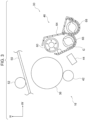
Fig. 2 is a diagram of, for example, an image carrier unit and a development unit included in an image forming apparatus according to an exemplary embodiment of the present disclosure; -
Fig. 3 is a diagram of, for example, an image carrier unit and a development unit included in an image forming apparatus according to an exemplary embodiment of the present disclosure; -
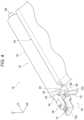
Fig. 4 is a perspective view of, for example, an image carrier unit and a development unit included in an image forming apparatus according to an exemplary embodiment of the present disclosure; -
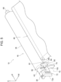
Fig. 5 is a perspective view of, for example, an image carrier unit and a development unit included in an image forming apparatus according to an exemplary embodiment of the present disclosure; -
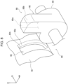
Figs. 6A and 6B are perspective views of a positioning structure of an image carrier unit included in an image forming apparatus according to an exemplary embodiment of the present disclosure; -
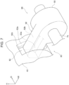
Fig. 7 is an enlarged perspective view of a portion of a positioning structure of an image carrier unit included in an image forming apparatus according to an exemplary embodiment of the present disclosure; and -
Fig. 8 is an enlarged perspective view of a portion of a positioning structure of an image carrier unit included in an image forming apparatus according to an exemplary embodiment of the present disclosure. - With reference to
Fig. 1 to Fig. 8 , an image forming apparatus according to an exemplary embodiment of the present disclosure is described. In the drawings, an arrow H denotes the apparatus height direction (the vertical direction), an arrow W denotes the apparatus width direction (the horizontal direction), and an arrow D denotes the apparatus depth direction (the horizontal direction). - As illustrated in
Fig. 1 , animage forming apparatus 10 includes animage forming portion 12 that forms toner images through an electrophotographic system, and atransport portion 14 that transports sheet members P serving as recording media along atransport path 14a. Theimage forming apparatus 10 includes acontainer member 18 that accommodates the sheet members P, and acontroller 28 that controls the entire apparatus. - In the
image forming apparatus 10 with this structure, thetransport portion 14 transports the sheet members P accommodated in thecontainer member 18 along thetransport path 14a. Then, toner images formed by theimage forming portion 12 are formed on the sheet members P, and the sheet members P on which the toner images are formed are discharged to the outside from anapparatus body 10a. - As illustrated in
Fig. 1 , theimage forming portion 12 includes multiple tonerimage forming portions 30 each forming toner images of a different color, and atransfer portion 32 that transfers the toner images formed by the tonerimage forming portions 30 to the sheet members P. Theimage forming portion 12 also includes afixing device 34 that fixes the toner images transferred to the sheet members P by thetransfer portion 32 to the sheet members P. - The multiple toner
image forming portions 30 each form toner images of a different color. In the present exemplary embodiment, the tonerimage forming portions 30 include tonerimage forming portions - The toner
image forming portions 30 for different colors have basically the same structure except for using different toner. As illustrated inFig. 2 , each tonerimage forming portion 30 includes animage carrier unit 16 including a rotatablecylindrical image carrier 36 and acharging device 42 that charges theimage carrier 36 with electricity. Each tonerimage forming portion 30 includes anexposure device 44 that irradiates thecharged image carrier 36 with exposure light to form electrostatic latent images, and a developingdevice 46 that develops the electrostatic latent images with a developer G containing toner into toner images. Thus, the tonerimage forming portions 30 for different colors form images of the different colors with toner of the different colors. - As illustrated in
Fig. 1 , theimage carrier 36 for each color is in contact to a transfer belt 50 (described in detail below) that rotates. The tonerimage forming portions 30 for yellow (Y), magenta (M), cyan (C), and black (K) are arranged in this order from the upstream side in the rotation direction (indicated with an arrow in the drawing) of thetransfer belt 50. - As illustrated in
Fig. 1 , thetransfer portion 32 includes thetransfer belt 50, andfirst transfer rollers 52 each disposed opposite theimage carrier 36 of the corresponding color with thetransfer belt 50 interposed therebetween to transfer toner images formed on theimage carrier 36 to thetransfer belt 50. - The
transfer portion 32 includes awinding roller 56 around which thetransfer belt 50 is wound, and adriving roller 58 around which thetransfer belt 50 is wound and that transmits a rotational force to thetransfer belt 50. Thus, thetransfer belt 50 rotates in the arrow direction in the drawing. - The
transfer portion 32 also includes asecond transfer roller 54 disposed opposite thewinding roller 56 with thetransfer belt 50 interposed therebetween and that transfers toner images transferred to thetransfer belt 50 to the sheet members P. Between thesecond transfer roller 54 and thetransfer belt 50, a transfer nip NT that transfers the toner images to the sheet members P is formed. - In this structure, in order of yellow (Y), magenta (M), cyan (C), and black (K), toner images are first-transferred to the
transfer belt 50 by thefirst transfer rollers 52. In addition, thesecond transfer roller 54 transfers the toner images from thetransfer belt 50 to the sheet members P transported while being held between thetransfer belt 50 and thesecond transfer roller 54. In addition, the sheet members P to which the toner images are transferred are transported toward thefixing device 34. - When a retract lever not illustrated is operated to, for example, remove jammed sheets, the
first transfer rollers 52 and thetransfer belt 50 are moved, and thetransfer belt 50 is moved away from theimage carrier 36 as illustrated inFig. 3 . - As illustrated in
Fig. 1 , the fixingdevice 34 is disposed downstream from the transfer nip NT in the transport direction of the sheet members P. The fixingdevice 34 heats and presses the toner images transferred to the sheet members P to fix the toner images to the sheet members P. - As illustrated in
Fig. 1 , thetransport portion 14 includes adispatch roller 20 that dispatches the sheet members P accommodated in thecontainer member 18 to thetransport path 14a, and stop rollers 22 that block transport of the sheet members P dispatched by thedispatch roller 20 in an overlapping manner. Thetransport portion 14 also includesadjustment rollers 24 that adjust the timing at which the sheet members P are dispatched to the transfer nip NT, and dischargingrollers 26 that discharge the sheet members P to which the toner images are fixed by the fixingdevice 34 to the outside from theapparatus body 10a. - Subsequently, components such as the developing
device 46 and theimage carrier unit 16 are described. - As illustrated in
Fig. 2 , the developingdevice 46 includes ahousing 64, adevelopment roller 60 disposed opposite theimage carrier 36, asupply auger 66 that supplies the developer G to thedevelopment roller 60, and anagitation auger 68 that agitates the developer G. - The developing
device 46 is supported by theapparatus body 10a while being movable between a nearby position (refer toFig. 2 ) in which thedevelopment roller 60 is disposed near theimage carrier 36 and a far position (refer toFig. 3 ) in which thedevelopment roller 60 is disposed away from theimage carrier 36. When thedevelopment roller 60 passes toner to theimage carrier 36 on which the electrostatic latent image is formed while thedevelopment roller 60 is in the nearby position, the electrostatic latent image is developed into a toner image. - The
image carrier unit 16 illustrated inFig. 2 is supported by theapparatus body 10a to be attachable to and removable from theapparatus body 10a by being moved in the apparatus depth direction. - More specifically, the
apparatus body 10a includes a covering, not illustrated, that covers the tonerimage forming portions 30 from the near side in the apparatus depth direction. While the covering is opened to expose the tonerimage forming portions 30, eachimage carrier unit 16 is attached to and removed from theapparatus body 10a. - As illustrated in
Fig. 4 , theimage carrier unit 16 includes ahandle 38 to be held by an operator to attach or detach theimage carrier unit 16 to or from theapparatus body 10a. Thehandle 38 is disposed on theimage carrier 36 on the near side in the apparatus depth direction. Between thehandle 38 and theimage carrier 36 in the apparatus depth direction, acylindrical portion 40 having an axis in the apparatus depth direction is disposed. Thus, thehandle 38 is attached to theimage carrier 36 with thecylindrical portion 40 interposed therebetween. - The
handle 38 has a planar shape having surfaces facing in the vertical direction, and has a rectangular shape extending in the apparatus depth direction when viewed from above. On the upper surface of thehandle 38, multiple protrusions (not denoted with reference signs) extending in the apparatus width direction are arranged side by side in the apparatus depth direction. - As illustrated in
Fig. 4 , the developingdevice 46 includes anoperation portion 70 that moves, when operated, between a block position (refer toFig. 4 ) in which it blocks detachment of theimage carrier unit 16 and an allowance position (refer toFig. 5 ) in which it allows detachment of theimage carrier unit 16. When theoperation portion 70 is moved to the block position, thedevelopment roller 60 is disposed nearer the image carrier 36 (refer toFig. 2 ), and when theoperation portion 70 is moved to the allowance position, thedevelopment roller 60 is disposed away from the image carrier (refer toFig. 3 ). - In addition, as illustrated in
Figs. 6A and 6B , theimage forming apparatus 10 includes apositioning portion 80 that positions theimage carrier unit 16 relative to theapparatus body 10a in the attachment-removal direction (in the apparatus depth direction in the exemplary embodiment) of theimage carrier unit 16. - As illustrated in
Fig. 4 , theoperation portion 70 is disposed on a near side of the developingdevice 46 in the apparatus depth direction, and includes agripper member 72 to be held by an operator, and ashaft member 74 that rotatably supports thegripper member 72. - The
shaft member 74 is cylindrical, extends in the apparatus depth direction, and is rotatably supported by asupport member 102 attached to a frame not illustrated. More specifically, when viewed in the apparatus depth direction, theshaft member 74 is disposed on one side of theimage carrier 36 in the apparatus width direction, and is disposed away from theimage carrier unit 16. Thegripper member 72 is attached to theshaft member 74 on the near side in the apparatus depth direction. - The
gripper member 72 includes ablock portion 72a disposed on the near side of thehandle 38 in the apparatus depth direction while theoperation portion 70 is located in the block position. While theoperation portion 70 is located in the block position, theblock portion 72a has a planar shape having plate surfaces facing in the vertical direction, and has a rectangular shape extending in the apparatus width direction when viewed from above. On the upper surface of theblock portion 72a, multiple protrusions (not denoted with reference signs) extending in the apparatus depth direction are arranged side by side in the apparatus width direction. - At a
protrusion 88 in thepositioning portion 80, a cam member not illustrated is disposed, and a contact portion, not illustrated, of the developingdevice 46 is urged against the peripheral surface of the cam member. Thus, in association with the movement of theoperation portion 70, the developingdevice 46 moves between the nearby position (refer toFig. 2 ) in which thedevelopment roller 60 is disposed near theimage carrier 36 and the far position (refer toFig. 3 ) in which thedevelopment roller 60 is disposed away from theimage carrier 36. - More specifically, the
housing 64 of the developingdevice 46 extends in the apparatus depth direction, and is rotatably supported about the shaft member, not illustrated, disposed at the developingdevice 46. In association with the movement of theoperation portion 70, thehousing 64 of the developingdevice 46 rotates about the shaft member not illustrated with the cam member interposed therebetween, and the developingdevice 46 moves between the nearby position (refer toFig. 2 ) in which thedevelopment roller 60 is disposed near theimage carrier 36 and the far position (refer toFig. 3 ) in which thedevelopment roller 60 is disposed away from theimage carrier 36. - In this structure, the
operation portion 70 is restricted to a rotation range by a stopper not illustrated, and moves between the block position (refer toFig. 4 ) in which it blocks detachment of theimage carrier unit 16 and the allowance position (refer toFig. 5 ) in which it allows detachment of theimage carrier unit 16. - More specifically, in the state where the
gripper member 72 is moved to the block position, as illustrated inFig. 4 , theblock portion 72a of theoperation portion 70 overlaps thehandle 38 in theimage carrier unit 16 when viewed in the apparatus depth direction, and disposed on the near side of thehandle 38 in the apparatus depth direction. Thus, theoperation portion 70 that is moved to the block position blocks detachment of theimage carrier unit 16. In association with the movement of theoperation portion 70 to the block position, the developingdevice 46 is moved to the nearby position. - In contrast, in the state where the
operation portion 70 is moved to the allowance position, as illustrated inFig. 5 , thegripper member 72 is disposed away from theimage carrier unit 16 when viewed in the apparatus depth direction. Thus, theoperation portion 70 moved to the allowance position allows detachment of theimage carrier unit 16 to the near side in the apparatus depth direction. In association with the movement of theoperation portion 70 to the allowance position, the developingdevice 46 is moved to the far position. - As illustrated in
Fig. 4 andFig. 5 , the positioningportion 80 includes arecess 82 formed in thecylindrical portion 40 of theimage carrier unit 16, and theprotrusion 88 insertable into and removable from therecess 82 and movable in association with theoperation portion 70. - As illustrated in
Figs. 6A and 6B , therecess 82 is open toward theshaft member 74 in the apparatus width direction. In other words, therecess 82 is set back in the apparatus width direction. The apparatus width direction is an example of a cross direction. - As illustrated in
Fig. 7 andFig. 8 , therecess 82 extends in the circumferential direction of thecylindrical portion 40. Therecess 82 has aguide surface 82a and afar end surface 82b. Theguide surface 82a guides theprotrusion 88 to therecess 82 during insertion of theprotrusion 88 into therecess 82. Thefar end surface 82b faces the near side in the apparatus depth direction. - The
guide surface 82a of therecess 82 is disposed at the opening on the far side in the apparatus depth direction to extend in the circumferential direction of thecylindrical portion 40. Theguide surface 82a is inclined with respect to the apparatus width direction to increase the opening width of therecess 82 in the apparatus depth direction. Thefar end surface 82b is disposed to be in contact with the edge of theguide surface 82a on the near side in the depth direction. Theguide surface 82a is also inclined with respect to the radial direction of thecylindrical portion 40. - In contrast, as illustrated in
Figs. 6A and 6B , theprotrusion 88 is attached to theshaft member 74 of theoperation portion 70, and includes abase portion 90 that surrounds theshaft member 74, and a protrudingportion 92 that protrudes from thebase portion 90 in the radial direction of theshaft member 74. Theprotrusion 88 is an example of part of thepositioning portion 80. - As illustrated in
Fig. 7 andFig. 8 , the protrudingportion 92 has a rectangular cross section. The protrudingportion 92 has aguide surface 92a, which guides the protrudingportion 92 to therecess 82 when the protrudingportion 92 of theprotrusion 88 is inserted into therecess 82, and afar end surface 92b, which faces the far side in the apparatus depth direction. Theguide surface 92a is an example of another guide surface. - The
guide surface 92a of the protrudingportion 92 extends in the radial direction of theshaft member 74 at a portion on the far side in the apparatus depth direction, and is inclined with respect to the circumferential direction of theshaft member 74. Thefar end surface 92b is disposed to come into contact with the edge of theguide surface 92a on the far side in the depth direction. - The
image forming apparatus 10 includes an urging member 98 (refer toFig. 4 andFig. 5 ). When theoperation portion 70 in the allowance position is moved to the block position while theimage carrier unit 16 is attached to theapparatus body 10a, the urgingmember 98 urges theimage carrier unit 16 to bring theguide surface 82a of therecess 82 into contact with theguide surface 92a of the protrudingportion 92. - In this structure, as illustrated in
Fig. 5 , while theoperation portion 70 is disposed in the allowance position, theimage carrier unit 16 detached from theapparatus body 10a is moved to the far side in the apparatus depth direction to be attached to theapparatus body 10a. In this state, positioning of theimage carrier unit 16 relative to theapparatus body 10a is cancelled. As illustrated inFig. 4 , theoperation portion 70 in the allowance position is rotated to the block position. - When the
operation portion 70 in the allowance position is rotated to the block position, theguide surface 92a of the protrudingportion 92 of theprotrusion 88 in thepositioning portion 80 illustrated inFig. 7 andFig. 8 comes into contact with theguide surface 82a of therecess 82. More specifically, with the urging force of the urging member 98 (refer toFig. 4 ), theimage carrier unit 16 is urged to the near side in the apparatus depth direction, and theguide surface 82a of therecess 82 comes into contact with theguide surface 92a of the protrudingportion 92. In this manner, theprotrusion 88 is rotated while theguide surface 82a and theguide surface 92a come into contact with each other, and thus theprotrusion 88 is guided to and inserted into the recess 82 (refer toFig. 7 ). - In the state where the
protrusion 88 is inserted into therecess 82, theimage carrier unit 16 is urged to the near side in the apparatus depth direction by the urging force of the urgingmember 98, and thefar end surface 82b of therecess 82 comes into contact with thefar end surface 92b of the protrudingportion 92 of the protrusion 88 (refer toFig. 7 ). In this manner, theimage carrier unit 16 is positioned relative to theapparatus body 10a in the apparatus depth direction. - When the
operation portion 70 in the block position is rotated to the allowance position, the protrudingportion 92 of theprotrusion 88 illustrated inFig. 7 andFig. 8 is removed from therecess 82, and positioning of theimage carrier unit 16 relative to theapparatus body 10a is cancelled. - In this manner, the
protrusion 88 in thepositioning portion 80 is inserted into or removed from therecess 82 with transmission of the moving force of theoperation portion 70. The moving force is an operating force caused by operating theoperation portion 70 to move theprotrusion 88. - As described above, in the
image forming apparatus 10, while theimage carrier unit 16 is attached to theapparatus body 10a and theoperation portion 70 is disposed in the allowance position, as illustrated inFig. 3 , thedevelopment roller 60 is disposed in the far position in which it is disposed away from theimage carrier 36. When theoperation portion 70 in the allowance position is rotated to the block position, as illustrated inFig. 2 , thedevelopment roller 60 is moved to the nearby position in which it is disposed near theimage carrier 36. As illustrated inFig. 4 , theblock portion 72a of thegripper member 72 in theoperation portion 70 is disposed on the near side of thehandle 38 in theimage carrier unit 16 in the apparatus depth direction. This structure blocks a movement of theimage carrier unit 16 to the near side in the apparatus depth direction and detachment of theimage carrier unit 16 from theapparatus body 10a. In association with the rotation of theoperation portion 70, theprotrusion 88 in thepositioning portion 80 is rotated, and the protrudingportion 92 of theprotrusion 88 is inserted into therecess 82. Thus, theimage carrier unit 16 is positioned relative to theapparatus body 10a in the apparatus depth direction. - In the structure where the
development roller 60 is moved toward and away from theimage carrier 36 in association with the operation on theoperation portion 70 that blocks or allows detachment of theimage carrier unit 16, theimage carrier unit 16 is positioned relative to theapparatus body 10a without independently operating thepositioning portion 80. - In the
image forming apparatus 10, when theoperation portion 70 in the block position is rotated to the allowance position, as illustrated inFig. 5 , the protrudingportion 92 of theprotrusion 88 in thepositioning portion 80 is removed from therecess 82, and positioning of theimage carrier unit 16 relative to theapparatus body 10a is cancelled. In this manner, positioning of theimage carrier unit 16 is cancelled without independently operating the positioning portion. - In the
image forming apparatus 10, theprotrusion 88 in thepositioning portion 80 is inserted into and removed from therecess 82 with transmission of the moving force of theoperation portion 70. In other words, with transmission of the moving force of theoperation portion 70, the positioningportion 80 positions theimage carrier unit 16 relative to theapparatus body 10a, or cancels the positioning of theimage carrier unit 16 relative to theapparatus body 10a. In this manner, the positioningportion 80 is activated without operating an actuator with electricity. - In the
image forming apparatus 10, theoperation portion 70 includes thegripper member 72 to be held by an operator, and theshaft member 74 that rotatably supports thegripper member 72. Theprotrusion 88 in thepositioning portion 80 is attached to theshaft member 74. Theprotrusion 88 rotates with the rotational force of theshaft member 74 to be inserted into and removed from therecess 82. Thus, the mechanism of transmitting the moving force has a simpler structure than a structure that uses a link to transmit the moving force of the operation portion to the positioning portion. - In the
image forming apparatus 10, the positioningportion 80 includes therecess 82 set back in the apparatus width direction, which is a cross direction crossing the apparatus depth direction or the attachment-removal direction of theimage carrier unit 16, and the protrudingportion 92 of theprotrusion 88 insertable into and removable from therecess 82 and movable in association with theoperation portion 70. Therecess 82 and theprotrusion 88 are disposed in theimage carrier unit 16 on the near side in the apparatus depth direction. In other words, therecess 82 and theprotrusion 88 are disposed in theimage carrier unit 16 on the removal side in the attachment-removal direction. As described above, therecess 82 and theprotrusion 88 are disposed at a portion on the nearer side in the apparatus depth direction than in the case where the image carrier unit is positioned by fitting the protrusion and the recess set back in the apparatus depth direction or the attachment-removal direction of the image carrier unit to each other. - In the
image forming apparatus 10, the protrudingportion 92 of theprotrusion 88 in thepositioning portion 80 has theguide surface 92a that guides the protrudingportion 92 to therecess 82 during insertion of the protrudingportion 92 into therecess 82. In addition, therecess 82 in thepositioning portion 80 has theguide surface 82a that is inclined with respect to the apparatus width direction, that may come into contact with theguide surface 92a, and that guides the protrudingportion 92 of theprotrusion 88 to therecess 82 during insertion of the protrudingportion 92 into therecess 82. Thus, the protrudingportion 92 of theprotrusion 88 is more easily inserted into therecess 82 than when the recess has a rectangular cross section and the protruding portion has a rectangular cross section. - The
image forming apparatus 10 includes the urgingmember 98 that urges theimage carrier unit 16 to bring theguide surface 82a of therecess 82 into contact with theguide surface 92a of the protrudingportion 92 during insertion of the protrudingportion 92 of theprotrusion 88 in thepositioning portion 80 into therecess 82. Thus, the protrudingportion 92 of theprotrusion 88 is more smoothly inserted into therecess 82 than in the case where theguide surface 82a wobbles relative to theguide surface 92a. - The
image forming apparatus 10 includes the urgingmember 98 that urges theimage carrier unit 16 and brings thefar end surface 82b of therecess 82 into contact with thefar end surface 92b of the protrudingportion 92 when the protrudingportion 92 of theprotrusion 88 in thepositioning portion 80 is inserted into therecess 82. Thus, compared to the case where the protrusion inserted into the recess wobbles relative to the recess, this structure improves positioning accuracy of theimage carrier unit 16 relative to theapparatus body 10a. - The present disclosure is described in detail based on a specific exemplary embodiment. However, it is apparent to those skilled in the art that the present disclosure is not limited to the exemplary embodiment, and may employ various other exemplary embodiments within the scope of the present disclosure. For example, in the exemplary embodiment, with transmission of the moving force of the
operation portion 70, the positioningportion 80 positions theimage carrier unit 16 relative to theapparatus body 10a or cancels the positioning of theimage carrier unit 16 relative to theapparatus body 10a. Instead, for example, the positioning portion may be activated by operating an actuator with electricity in association with rotation of the operation portion. This structure has no effect caused by the positioningportion 80 being activated with the moving force of theoperation portion 70. - In the above exemplary embodiment, the
protrusion 88 included in thepositioning portion 80 is attached to theshaft member 74, and is inserted into and removed from therecess 82 with transmission of the rotational force of therotating shaft member 74. Instead, the moving force of theoperation portion 70 may be transmitted to theprotrusion 88 using, for example, a link. This structure has no effect caused by theprotrusion 88 being inserted into and removed from therecess 82 with transmission of the rotational force of therotating shaft member 74. - In the above exemplary embodiment, the protruding
portion 92 of theprotrusion 88 in thepositioning portion 80 has theguide surface 92a, and therecess 82 has theguide surface 82a. Instead, for example, the recess may have a rectangular cross section, or the protruding portion may have a rectangular cross section. At least one of the recess or the protruding portion may have a rectangular cross section. This structure has no effect caused by theprotrusion 88 and therecess 82 each having a guide surface. - In the above exemplary embodiment, the urging
member 98 urges theimage carrier unit 16 to the near side in the apparatus depth direction. Instead, a restriction member that restricts the range of movement of theimage carrier unit 16 in the apparatus depth direction while the urgingmember 98 urges theimage carrier unit 16 may be provided. More specifically, when a restriction member restricts the range of movement of theimage carrier unit 16 to bring theguide surface 82a and theguide surface 92a into contact with each other, theguide surface 92a effectively comes into contact with theguide surface 82a. - In the above exemplary embodiment, the
recess 82 in thepositioning portion 80 is formed in theimage carrier unit 16, and theprotrusion 88 is attached to theshaft member 74. Instead, the protrusion may be attached to the image carrier unit, and the recess may be formed in the shaft member. - The foregoing description of the exemplary embodiments of the present disclosure has been provided for the purposes of illustration and description. It is not intended to be exhaustive or to limit the disclosure to the precise forms disclosed. Obviously, many modifications and variations will be apparent to practitioners skilled in the art. The embodiments were chosen and described in order to best explain the principles of the disclosure and its practical applications, thereby enabling others skilled in the art to understand the disclosure for various embodiments and with the various modifications as are suited to the particular use contemplated. It is intended that the scope of the disclosure be defined by the following claims and their equivalents.
-
- (((1))) An image forming apparatus comprising:
- an image carrier unit that is attachable to and removable from an apparatus body and that includes an image carrier;
- a development roller that passes toner to the image carrier when located in a position near the image carrier;
- an operation portion that moves, when operated, between a block position in which the operation portion blocks detachment of the image carrier unit from the apparatus body and an allowance position in which the operation portion allows detachment of the image carrier unit from the apparatus body, the development roller moving toward the image carrier in association with a movement of the operation portion to the block position, the development roller moving away from the image carrier in association with a movement of the operation portion to the allowance position; and
- a positioning portion that positions the image carrier unit relative to the apparatus body in an attachment-removal direction of the image carrier unit when the operation portion is moved to the block position.
- (((2))) The image forming apparatus according to (((1))),
wherein, when the operation portion is moved to the allowance position, the positioning portion cancels positioning of the image carrier unit relative to the apparatus body. - (((3))) The image forming apparatus according to (((2))),
wherein the positioning portion positions the image carrier unit relative to the apparatus body and cancels positioning of the image carrier unit relative to the apparatus body with direct or indirect transmission of a moving force of the operation portion. - (((4))) The image forming apparatus according to (((3))),
- wherein the operation portion includes a gripper member to be held by an operator and a shaft member that rotatably supports the gripper member, and
- wherein part of the positioning portion is directly attached to the shaft member.
- (((5))) The image forming apparatus according to any one of (((1))) to (((4))),
wherein the positioning portion includes a recess formed in the image carrier unit and set back in a cross direction that crosses the attachment-removal direction of the image carrier unit, and a protrusion that moves together with the operation portion and that is inserted into and removed from the recess. - (((6))) The image forming apparatus according to (((5))),
- wherein the operation portion includes a gripper member to be held by an operator and a shaft member that rotatably supports the gripper member and that extends in the attachment-removal direction,
- wherein the protrusion is attached to the shaft member, and protrudes in a radial direction of the shaft member,
- wherein the recess is recessed in the cross direction to allow the protrusion that rotates to be inserted into and removed from the recess,
- wherein the recess has a first guide surface that guides the protrusion to the recess during insertion of the protrusion into the recess, the first guide surface being inclined with respect to the cross direction to increase an opening width of the recess, and
- wherein the protrusion has a second guide surface that guides the protrusion to the recess and that is allowed to come into contact with the first guide surface during insertion of the protrusion into the recess, the second guide surface being inclined with respect to a circumferential direction of the shaft member.
- In the image forming apparatus according to (((1))), in the structure where the development roller is moved toward and away from the image carrier in association with the operation on the operation portion that blocks or allows detachment of the image carrier unit, the image carrier unit is allowed to be positioned relative to the apparatus body without independently operating the positioning portion.
- In the image forming apparatus according to (((2))), the positioning of the image carrier unit may be cancelled without independently operating the positioning portion.
- In the image forming apparatus according to (((3))), the positioning portion may be activated without operating an actuator with electricity.
- In the image forming apparatus according to (((4))), a structure that transmits the moving force of the operation portion may have a simpler structure than in the structure using a link to transmit the moving force of the operation portion to the positioning portion.
- In the image forming apparatus according to (((5)), the positioning portion may be disposed further on a detachment side in the attachment-detachment direction than in the case where the image carrier unit is positioned by fitting a protrusion and a recess set back in the attachment-detachment direction of the image carrier unit to each other.
- In the image forming apparatus according to (((6))), a protrusion is more easily insertable into a recess than in the case where the recess has a rectangular cross section and the protrusion has a rectangular cross section.
Claims (6)
- An image forming apparatus comprising:an image carrier unit that is attachable to and removable from an apparatus body and that includes an image carrier;a development roller that passes toner to the image carrier when located in a position near the image carrier;an operation portion that moves, when operated, between a block position in which the operation portion blocks detachment of the image carrier unit from the apparatus body and an allowance position in which the operation portion allows detachment of the image carrier unit from the apparatus body, the development roller moving toward the image carrier in association with a movement of the operation portion to the block position, the development roller moving away from the image carrier in association with a movement of the operation portion to the allowance position; anda positioning portion that positions the image carrier unit relative to the apparatus body in an attachment-removal direction of the image carrier unit when the operation portion is moved to the block position.
- The image forming apparatus according to claim 1,
wherein, when the operation portion is moved to the allowance position, the positioning portion cancels positioning of the image carrier unit relative to the apparatus body. - The image forming apparatus according to either claim 1 or claim 2,
wherein the positioning portion positions the image carrier unit relative to the apparatus body and cancels positioning of the image carrier unit relative to the apparatus body with direct or indirect transmission of a moving force of the operation portion. - The image forming apparatus according to any one of claims 1 to 3,wherein the operation portion includes a gripper member to be held by an operator and a shaft member that rotatably supports the gripper member, andwherein part of the positioning portion is directly attached to the shaft member.
- The image forming apparatus according to any one of claims 1 to 4,
wherein the positioning portion includes a recess formed in the image carrier unit and set back in a cross direction that crosses the attachment-removal direction of the image carrier unit, and a protrusion that moves together with the operation portion and that is inserted into and removed from the recess. - The image forming apparatus according to any one of claims 1 to 5,wherein the operation portion includes a gripper member to be held by an operator and a shaft member that rotatably supports the gripper member and that extends in the attachment-removal direction,wherein the protrusion is attached to the shaft member, and protrudes in a radial direction of the shaft member,wherein the recess is recessed in the cross direction to allow the protrusion that rotates to be inserted into and removed from the recess,wherein the recess has a first guide surface that guides the protrusion to the recess during insertion of the protrusion into the recess, the first guide surface being inclined with respect to the cross direction to increase an opening width of the recess, andwherein the protrusion has a second guide surface that guides the protrusion to the recess and that is allowed to come into contact with the first guide surface during insertion of the protrusion into the recess, the second guide surface being inclined with respect to a circumferential direction of the shaft member.
Applications Claiming Priority (1)
| Application Number | Priority Date | Filing Date | Title |
|---|---|---|---|
| JP2023102051A JP2025002115A (en) | 2023-06-21 | 2023-06-21 | Image formation apparatus |
Publications (1)
| Publication Number | Publication Date |
|---|---|
| EP4481505A1 true EP4481505A1 (en) | 2024-12-25 |
Family
ID=88874812
Family Applications (1)
| Application Number | Title | Priority Date | Filing Date |
|---|---|---|---|
| EP23210898.5A Pending EP4481505A1 (en) | 2023-06-21 | 2023-11-20 | Image forming apparatus |
Country Status (4)
| Country | Link |
|---|---|
| US (1) | US20240427271A1 (en) |
| EP (1) | EP4481505A1 (en) |
| JP (1) | JP2025002115A (en) |
| CN (1) | CN119179247A (en) |
Citations (4)
| Publication number | Priority date | Publication date | Assignee | Title |
|---|---|---|---|---|
| EP1457841A2 (en) * | 2003-03-14 | 2004-09-15 | Brother Kogyo Kabushiki Kaisha | Colour image forming apparatus with removable developing units |
| JP2015191070A (en) | 2014-03-27 | 2015-11-02 | 富士ゼロックス株式会社 | Process cartridge and image forming apparatus using the same |
| US20220137547A1 (en) * | 2020-10-30 | 2022-05-05 | Brother Kogyo Kabushiki Kaisha | Image forming apparatus |
| US20220373959A1 (en) * | 2021-05-20 | 2022-11-24 | Shinichi Arasawa | Image forming apparatus |
-
2023
- 2023-06-21 JP JP2023102051A patent/JP2025002115A/en active Pending
- 2023-11-17 US US18/512,476 patent/US20240427271A1/en active Pending
- 2023-11-20 EP EP23210898.5A patent/EP4481505A1/en active Pending
- 2023-11-20 CN CN202311551729.3A patent/CN119179247A/en active Pending
Patent Citations (4)
| Publication number | Priority date | Publication date | Assignee | Title |
|---|---|---|---|---|
| EP1457841A2 (en) * | 2003-03-14 | 2004-09-15 | Brother Kogyo Kabushiki Kaisha | Colour image forming apparatus with removable developing units |
| JP2015191070A (en) | 2014-03-27 | 2015-11-02 | 富士ゼロックス株式会社 | Process cartridge and image forming apparatus using the same |
| US20220137547A1 (en) * | 2020-10-30 | 2022-05-05 | Brother Kogyo Kabushiki Kaisha | Image forming apparatus |
| US20220373959A1 (en) * | 2021-05-20 | 2022-11-24 | Shinichi Arasawa | Image forming apparatus |
Also Published As
| Publication number | Publication date |
|---|---|
| JP2025002115A (en) | 2025-01-09 |
| CN119179247A (en) | 2024-12-24 |
| US20240427271A1 (en) | 2024-12-26 |
Similar Documents
| Publication | Publication Date | Title |
|---|---|---|
| US7272339B2 (en) | Process cartridge including first and second frames and separating member moving the second frame to a separated position and image forming apparatus detachably mounting the cartridge | |
| CN110850699B (en) | Image forming apparatus and process cartridge | |
| US7929881B2 (en) | Process cartridge and electrophotographic image forming apparatus | |
| US10095180B2 (en) | Developing cartridge which is movable toward and away from image bearing member | |
| EP3211483B1 (en) | Developing cartridge and image forming apparatus | |
| US20210263463A1 (en) | Developing apparatus, process cartridge, and image forming apparatus | |
| US12271145B2 (en) | Image forming apparatus | |
| US10203655B2 (en) | Image forming apparatus | |
| US20200401080A1 (en) | Attachment, set of mountable and dismountable units, electrophotographic image forming apparatus and cartridge mounting method | |
| US9417604B2 (en) | Image forming apparatus | |
| US20190196392A1 (en) | Image forming apparatus | |
| US8488993B2 (en) | Image forming device having process unit that can be pulled out thereof | |
| US9348305B2 (en) | Image forming apparatus with a cartridge that includes and image bearing member | |
| US9164476B2 (en) | Toner cartridge having structure for minimizing deformation when gripped | |
| JP6938166B2 (en) | Image forming device | |
| US20240427271A1 (en) | Image forming apparatus | |
| CN103019074A (en) | Image forming apparatus and transfer device | |
| US10649400B2 (en) | Image forming apparatus with features that suppress deformation of door caused by counterforce from cartridge | |
| US10935906B2 (en) | Developer supply device and image forming apparatus incorporating same | |
| US20110236067A1 (en) | Fixing device, single-sided image forming apparatus, and double-sided image forming apparatus | |
| US7706719B2 (en) | Image forming apparatus with an openable section at an upper face side or a front face side | |
| KR102574239B1 (en) | Image forming apparatus and developing cartridge | |
| JP7214419B2 (en) | Image forming apparatus, developing cartridge | |
| JP2000276022A (en) | Image forming device | |
| JP2019179258A (en) | Storage container and image forming apparatus |
Legal Events
| Date | Code | Title | Description |
|---|---|---|---|
| PUAI | Public reference made under article 153(3) epc to a published international application that has entered the european phase |
Free format text: ORIGINAL CODE: 0009012 |
|
| STAA | Information on the status of an ep patent application or granted ep patent |
Free format text: STATUS: THE APPLICATION HAS BEEN PUBLISHED |
|
| AK | Designated contracting states |
Kind code of ref document: A1 Designated state(s): AL AT BE BG CH CY CZ DE DK EE ES FI FR GB GR HR HU IE IS IT LI LT LU LV MC ME MK MT NL NO PL PT RO RS SE SI SK SM TR |
|
| STAA | Information on the status of an ep patent application or granted ep patent |
Free format text: STATUS: REQUEST FOR EXAMINATION WAS MADE |
|
| 17P | Request for examination filed |
Effective date: 20250113 |