EP4481452A2 - Multi-fiber fiber optic connector having enhanced functionality - Google Patents
Multi-fiber fiber optic connector having enhanced functionality Download PDFInfo
- Publication number
- EP4481452A2 EP4481452A2 EP24210319.0A EP24210319A EP4481452A2 EP 4481452 A2 EP4481452 A2 EP 4481452A2 EP 24210319 A EP24210319 A EP 24210319A EP 4481452 A2 EP4481452 A2 EP 4481452A2
- Authority
- EP
- European Patent Office
- Prior art keywords
- key
- connector body
- connector
- fiber optic
- fiber
- Prior art date
- Legal status (The legal status is an assumption and is not a legal conclusion. Google has not performed a legal analysis and makes no representation as to the accuracy of the status listed.)
- Pending
Links
Images










Classifications
-
- G—PHYSICS
- G02—OPTICS
- G02B—OPTICAL ELEMENTS, SYSTEMS OR APPARATUS
- G02B6/00—Light guides; Structural details of arrangements comprising light guides and other optical elements, e.g. couplings
- G02B6/24—Coupling light guides
- G02B6/36—Mechanical coupling means
- G02B6/38—Mechanical coupling means having fibre to fibre mating means
- G02B6/3807—Dismountable connectors, i.e. comprising plugs
- G02B6/3873—Connectors using guide surfaces for aligning ferrule ends, e.g. tubes, sleeves, V-grooves, rods, pins, balls
- G02B6/3885—Multicore or multichannel optical connectors, i.e. one single ferrule containing more than one fibre, e.g. ribbon type
-
- G—PHYSICS
- G02—OPTICS
- G02B—OPTICAL ELEMENTS, SYSTEMS OR APPARATUS
- G02B6/00—Light guides; Structural details of arrangements comprising light guides and other optical elements, e.g. couplings
- G02B6/24—Coupling light guides
- G02B6/36—Mechanical coupling means
- G02B6/38—Mechanical coupling means having fibre to fibre mating means
- G02B6/3807—Dismountable connectors, i.e. comprising plugs
- G02B6/381—Dismountable connectors, i.e. comprising plugs of the ferrule type, e.g. fibre ends embedded in ferrules, connecting a pair of fibres
- G02B6/3826—Dismountable connectors, i.e. comprising plugs of the ferrule type, e.g. fibre ends embedded in ferrules, connecting a pair of fibres characterised by form or shape
- G02B6/3831—Dismountable connectors, i.e. comprising plugs of the ferrule type, e.g. fibre ends embedded in ferrules, connecting a pair of fibres characterised by form or shape comprising a keying element on the plug or adapter, e.g. to forbid wrong connection
-
- G—PHYSICS
- G02—OPTICS
- G02B—OPTICAL ELEMENTS, SYSTEMS OR APPARATUS
- G02B6/00—Light guides; Structural details of arrangements comprising light guides and other optical elements, e.g. couplings
- G02B6/24—Coupling light guides
- G02B6/36—Mechanical coupling means
- G02B6/38—Mechanical coupling means having fibre to fibre mating means
- G02B6/3807—Dismountable connectors, i.e. comprising plugs
- G02B6/389—Dismountable connectors, i.e. comprising plugs characterised by the method of fastening connecting plugs and sockets, e.g. screw- or nut-lock, snap-in, bayonet type
- G02B6/3893—Push-pull type, e.g. snap-in, push-on
-
- G—PHYSICS
- G02—OPTICS
- G02B—OPTICAL ELEMENTS, SYSTEMS OR APPARATUS
- G02B6/00—Light guides; Structural details of arrangements comprising light guides and other optical elements, e.g. couplings
- G02B6/24—Coupling light guides
- G02B6/36—Mechanical coupling means
- G02B6/38—Mechanical coupling means having fibre to fibre mating means
- G02B6/3807—Dismountable connectors, i.e. comprising plugs
- G02B6/381—Dismountable connectors, i.e. comprising plugs of the ferrule type, e.g. fibre ends embedded in ferrules, connecting a pair of fibres
- G02B6/3818—Dismountable connectors, i.e. comprising plugs of the ferrule type, e.g. fibre ends embedded in ferrules, connecting a pair of fibres of a low-reflection-loss type
- G02B6/3821—Dismountable connectors, i.e. comprising plugs of the ferrule type, e.g. fibre ends embedded in ferrules, connecting a pair of fibres of a low-reflection-loss type with axial spring biasing or loading means
-
- G—PHYSICS
- G02—OPTICS
- G02B—OPTICAL ELEMENTS, SYSTEMS OR APPARATUS
- G02B6/00—Light guides; Structural details of arrangements comprising light guides and other optical elements, e.g. couplings
- G02B6/24—Coupling light guides
- G02B6/36—Mechanical coupling means
- G02B6/38—Mechanical coupling means having fibre to fibre mating means
- G02B6/3807—Dismountable connectors, i.e. comprising plugs
- G02B6/3873—Connectors using guide surfaces for aligning ferrule ends, e.g. tubes, sleeves, V-grooves, rods, pins, balls
- G02B6/3882—Connectors using guide surfaces for aligning ferrule ends, e.g. tubes, sleeves, V-grooves, rods, pins, balls using rods, pins or balls to align a pair of ferrule ends
Definitions
- the present disclosure relates generally to fiber optic connectors. More particularly, the present disclosure relates to multi-fiber fiber optic connectors.
- a multi-fiber fiber optic connector typically includes a connector body supporting a multi-fiber ferrule at a front end and a connector boot at a rear end.
- an outer release-sleeve i.e., a grip-sleeve
- the outer release-sleeve is slidable relative to the connector body and is spring biased toward a forward position.
- the release-sleeve covers latches of the fiber optic adapter to retain the latches in latched positions relative to the connector body such that the fiber optic connector is prevented from being withdrawn from the adapter.
- the release-sleeve By pulling back on the release-sleeve, the release-sleeve is displaced from the latches of the fiber optic adapter such that the latches can flex outwardly to unlatched positions in which multi-fiber fiber optic connector can be withdrawn from the fiber optic adapter.
- An MPO connector can either be male or female.
- a male MPO connector includes two alignment pins that project forwardly from the multi-fiber ferrule of the connector.
- a female MOP connector includes alignment openings within the multi-fiber ferrule adapted to receive the alignment pins of a mating male MPO connector. The ability to change genders between male and female MPO connectors in the field is desirable.
- MPO connectors typically include a key integrated with the connector housing for determining the polarity of the fiber optic connectors. Depending on the fiber optic system into which the MPO connector is intended to be incorporated, it may be required to have a key on either a bottom side or a top side of the fiber optic connector.
- the multi-fiber fiber optic connector has a connector body with a front end.
- the multi-fiber fiber optic connector also includes a multi-fiber ferrule positioned at the front end of the connector body.
- the fiber optic connector further includes an outer grip-sleeve assembly that mounts on the connector body.
- the outer grip-sleeve assembly includes a main grip-sleeve body and two separate adapter latch locks mounted at opposite sides of the main grip-sleeve body.
- the adapter latch locks are slidably movable relative to the main grip-sleeve body and are independently movable relative to one another. Separate springs bias the adapter latch locks toward forward positions relative to the main grip-sleeve body, and also bias the main grip-sleeve body toward a forward position relative to the connector body.
- a multi-fiber fiber optic connector including a connector body having a front end.
- the fiber optic connector also includes a multi-fiber ferrule mounted at the front end of the connector body.
- the fiber optic connector also includes an outer grip-sleeve that mounts on the connector body.
- the outer grip-sleeve is mounted to slide longitudinally relative to the connector body and is spring biased toward a forward position relative to the connector body.
- the fiber optic connector further includes keys slidably mounted at top and bottom sides of the connector body. The keys are each slidably movable relative to the connector body between an extended position and a retracted position. Each of the keys includes first and second latches.
- the connector body defines latch receptacles that are defined at the top and bottom sides of the connector body and that are covered by the outer grip-sleeve.
- the outer grip-sleeve includes latch blocking surfaces that cover the latch receptacles to provide key latch retention when the outer grip-sleeve is in the forward position.
- the latch blocking surfaces are offset from the latch receptacles to allow key latch disengagement from the latch key receptacles.
- the keys are in the extended positions, the first key latches engage with the key latch receptacles. In contrast, when the keys are in the retracted positions, the second key latches engage with the latch receptacles.
- a fiber optic connector including a connector body having a front end.
- the fiber optic connector also includes a multi-fiber ferrule positioned at the front end of the connector body.
- the fiber optic connector further includes a grip-sleeve mounted on the connector body.
- the fiber optic connector includes alignment pins mountable within alignment pin openings defined by the multi-fiber ferrule.
- the alignment pins include circumferential retention grooves adjacent rear ends of the alignment pins.
- the fiber optic connector includes an alignment pin retention structure including resilient spring elements.
- the resilient spring elements include pin retaining portions that are moveable between pin retaining positions and pin release positions, and that are spring biased toward the pin retaining positions.
- the pin retaining portions fit within the circumferential grooves at inner sides of the alignment pins, and are moved from the pin retaining positions to the pin release positions by flexing the pin retaining portions inwardly toward a central axis of the fiber optic connector.
- the pin retaining portions fit within the circumferential grooves at outer sides of the alignment pins, and are moved from the pin retaining positions to the pin release positions by flexing the pin retaining portions outwardly away from the central axis of the fiber optic connector.
- a tool can be used to move each resilient spring element from the pin retaining position to the pin release position without requiring the fiber optic connector to be disassembled.
- FIGS. 1-7 depict a multi-fiber fiber optic connector 20 in accordance with the principles of the present disclosure.
- the multi-fiber fiber optic connector 20 has enhanced functionality at least relating to the ability to easily change polarity, the ability to easily change gender, and the ability to operate the multi-fiber fiber optic connector 20 as a true push-pull fiber optic connector (e.g., a true push-pull MPO connector).
- a true push-pull fiber optic connector is a connector in which the outer grip sleeve can be grasped during both insertion of the connector into a fiber optic adapter and during removal of the connector from the fiber optic adapter.
- the multi-fiber fiber optic connector 20 includes a connector body 22 having a front end 24 and an opposite rear end 26.
- a ferrule assembly 28 of the multi-fiber fiber optic connector 20 is configured to mount within an interior of the connector body 22.
- a spring 30 of the multi-fiber fiber optic connector 20 is configured to bias the ferrule assembly 28 in a forward direction relative to the connector body 22.
- the multi-fiber fiber optic connector 20 also includes a rear spring stop 32 configured to mount within the rear end 26 of the connector body 22.
- the rear spring stop 32 is configured to retain the spring 30 within the connector body 22.
- a rear connector boot 34 is configured to mount to a rear end of the rear spring stop 32.
- the rear connector boot 34 can have a flexible configuration for providing optical fiber bend radius protection and strain relief at the rear end of the multi-fiber fiber optic connector 20. It will be appreciated that in use, the connector 20 mounts at the end of a fiber optic cable, and the boot 34 preferably provides flexible support where the cable enters the rear of the connector.
- the multi-fiber fiber optic connector 20 further includes an outer grip-sleeve assembly 36 configured to mount over the connector body 22.
- the outer grip-sleeve assembly 36 includes a main grip-sleeve body 38 and separate left and right adapter latch locks 40a, 40b.
- Left and right grip-sleeve assembly springs 42a, 42b are used to bias the outer grip-sleeve assembly 36 in a forward direction when the outer grip-sleeve assembly 36 is mounted on the connector body 22.
- the left and right grip-sleeve assembly springs 42a, 42b respectively mount within left and right spring grooves 44a, 44b (see FIG. 8 ) defined by the connector body 22.
- the multi-fiber fiber optic connector 20 further includes upper and lower keys 46a, 46b adapted to be slidably mounted respectively at upper and lower major sides 48a, 48b of the connector body 42 adjacent the front end 24 of the connector body 22.
- the upper and lower major sides 48a, 48b of the connector body 22 extend lengthwise between the front end 24 and the rear end 26 of the connector body.
- the connector body 22 also includes opposite left and right minor sides 50a, 50b that extend between the upper and lower major sides 48a, 48b and also extend lengthwise between the front and rear ends 24, 26.
- the connector body 22 defines a longitudinal axis 52 that extends between the front and rear ends 24, 26.
- the left and right minor sides 50a, 50b respectively define left and right adapter latch receptacles 54a, 54b.
- the left and right minor sides 50a, 50b also define the left and right spring grooves 44a, 44b.
- the left and right spring grooves 44a, 44b can also be referred to as spring pockets and preferably include open longitudinal sides that respectively face outwardly in left and right directions.
- the left and right spring grooves 44a, 44b also include front and rear ends 56, 58 that preferably oppose and function as spring stops for opposite ends of the left and right grip-sleeve assembly springs 42a, 42b (see FIG. 8 ).
- the front ends 56 of the spring grooves 44a, 44b define rearwardly facing spring stop surfaces and the rear ends 58 of the spring grooves 44a, 44b include forwardly facing spring stop surfaces.
- the connector body 22 also includes structure for accommodating the upper and lower keys 46a, 46b.
- the upper and lower keys 46a, 46b respectively slidably mount to the upper and lower major sides 48a, 48b of the connector body 22. It is preferred for the upper and lower keys 46a, 46b to each be slidably movable along the longitudinal axis 52 relative to the connector body 22 between forward and rearward positions.
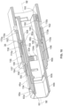
- the connector body 22 defines upper and lower longitudinal key mounting slots 60a, 60b (see FIGS. 14-16 , 32 and 33 ) that extend longitudinally along the connector body 22 in a rearward direction from the front end 24 of the connector body 22.
- the key mounting slots 60a, 60b can each have a dovetail shaped transverse cross-sectional profile (see FIG. 32 ) adapted to receive mating projections 62 (see FIG. 30 ) of the upper and lower keys 46a, 46b.
- the projections 62 can have complimentary cross-sections with the transverse cross-sectional profiles of the key mounting slots 60a, 60b and are preferably also dovetail shaped (see FIGS. 30 and 31 ).
- the connector body 22 further includes upper and lower sets of key guides 64a, 64b at the upper and lower major sides 48a, 48b (see FIGS. 14 , 32 and 33 ).
- the key guides 64a, 64b are configured as guiderails that have lengths that extend along the longitudinal axis 52.
- the key guides 64a, 64b include opposing surfaces between which the upper and lower keys 46a, 46b slide.
- the connector body 22 further includes upper and lower key latch receptacles 66a, 66b (see FIGS. 14-16 , 32 and 33 ).
- the connector body 22 further includes exterior structures for retaining the outer grip-sleeve assembly 36 on the connector body 22 when the outer grip-sleeve assembly 36 has been installed over the connector body 22.
- the upper and lower key guides 64a, 64b include rear ends 68 which include rearwardly facing stop surfaces adapted to stop forward movement of the outer grip-sleeve assembly 36 relative to the connector body 22 once the outer grip-sleeve assembly 36 is mounted on the connector body 22 (see FIG. 27 ).
- the connector body 22 includes left and right side stops 70a, 70b (see FIGS. 27 , 32 and 33 ) near the rear end 26 of the connector body 22.
- the left and right side stops 70a, 70b include forwardly facing stop surfaces that are adapted to stop movement of the outer grip-sleeve assembly 36 in the rearward direction when the outer grip-sleeve assembly 36 is mounted on the connector body 22.
- the ferrule assembly 28 of the multi-fiber fiber optic connector 20 includes a multi-fiber ferrule 80 that is positioned within the connector body 22 adjacent the front end 24 of the connector body when the ferrule assembly 28 has been installed within the connector body 22.
- the multi-fiber ferrule 80 has an elongate transverse cross-sectional profile defining perpendicular major and minor dimensions 82, 84 (see FIGS. 6 and 7 ). With the multi-fiber ferrule 80 installed in the connector body 22, the major dimension 82 extends between the left and right minor sides 50a, 50b of the connector body 22 and the minor dimension 84 extends between the upper and lower major sides 48a, 48b of the connector body 22 (see FIG. 6 ).
- the multi-fiber ferrule 80 defines a plurality of fiber openings 86 (see FIG. 8 ) for receiving optical fibers corresponding to a fiber optic cable which is terminated by the multi-fiber fiber optic connector 20. At least some of the fiber openings 86 are arranged in a row that extends along the major dimension 82 of the multi-fiber ferrule 80.
- the multi-fiber ferrule 80 when installed in the connector body 22, is preferably movable relative to the connector body along the longitudinal axis 52 and is spring biased toward a forward position relative to the connector body 22 by the ferrule biasing spring 30 (see FIG. 8 ).
- the ferrule assembly 28 also includes left and right ferrule alignment pins 88a, 88b that mount within corresponding left and right alignment pin openings 90a, 90b when the multi-fiber fiber optic connector 20 is configured as a male connector.
- the ferrule alignment pins 88a, 88b When the ferrule alignment pins 88a, 88b are mounted within the alignment pin openings 90a, 90b, the ferrule alignment pins 88a, 88b are retained within the alignment pin openings 90a, 90b by a pin retention structure 92 (i.e., a pin retention arrangement) that mounts at a rear end of multi-fiber ferrule 80.
- the pin retention structure 92 is held against the back end of the ferrule 80 by the ferrule biasing spring 30.
- the ferrule alignment pins 88a, 88b include circumferential grooves 94 (see FIG.
- the ferrule alignment pins 88a, 88b are not present within the alignment pin openings 90a, 90b such that when the female fiber optic connector is mated with a corresponding male fiber optic connector, the ferrule alignment pins of the male fiber optic connector can be received within the alignment pin openings 90a, 90b to provide alignment between the multi-fiber ferrules of the mated fiber optic connectors.
- the ferrule assembly 28 additionally includes a ferrule boot 96 that is assembled within the rear end of the multi-fiber ferrule 80.
- the ferrule boot 96 is configured for receiving the optical fibers that are routed into the multi-fiber ferrule 80 from the cable to which the multi-fiber connector 20 is terminated.
- the ferrule boot 96 can define a through passage for receiving optical fibers routed into the multi-fiber ferrule 80 from the optical cable to which the multi-fiber fiber optic connector 20 is terminated/mounted.
- the ferrule assembly 28, the ferrule biasing spring 30 and the rear spring stop 32 are all loaded into the connector body 22 through the rear end 26 of the connector body 22.
- the ferrule biasing spring 30 has a front end that seats against the pin retention structure 92 and a rear end that abuts against a spring seat 98 of the rear spring stop 32.
- the rear spring stop 32 includes left and right latching arms 100a, 100b which include retention tabs 102 that snap within corresponding left and right openings 104a, 104b defined by the left and right minor sides 50a, 50b of the connector body 22 when the rear spring stop 32 is loaded into the connector body 22.
- the left and right openings 104a, 104b coincide with (e.g., intersect with) front portions of the spring grooves 44a, 44b.
- a front shoulder 106 of the multi-fiber ferrule 80 abuts against a stop structure 108 within the connector body 22.
- the ferrule assembly 28 and the ferrule biasing spring 30 are thus captured within the connector body 22 between the stop structure 108 and the rear spring stop 32.
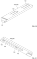
- the main grip-sleeve body 38 of the outer grip-sleeve assembly 36 includes upper and lower major sides 110a, 110b (see FIGS. 34 and 35 ) that respectively oppose the upper and lower major sides 48a, 48b of the connector body 22 when the main grip-sleeve body 38 is mounted on the connector body 22 (see FIGS. 1 and 2 ).
- the main grip-sleeve body 38 also includes left and right minor sides 112a, 112b (see FIGS. 34 and 35 ) that respectively oppose the left and right minor sides 50a, 50b of the connector body 22 when the main grip-sleeve body 38 is mounted on the connector body 22 (see FIGS. 1 and 2 ).
- the main grip-sleeve body 38 When mounted on the connector body 22, the main grip-sleeve body 38 is movable relative to the connector body 22 along the longitudinal axis 52 of the connector body 22 between a forward position (see FIG. 15 ) and a rearward position (see FIG. 16 ).
- the left and right minor sides 112a, 112b of the main grip-sleeve body 38 define left and right front notches 114a, 114b having open front ends 116 (see FIG. 34 ).
- the main grip-sleeve body 38 defines upper and lower viewing windows 118a, 118b defined respectively through the upper and lower major sides 110a, 110b of the main grip-sleeve body 38.
- the windows 118a, 118b allow a person to quickly visually determine a position (e.g., an extended/ active keying position or a retracted/inactive keying position) of plurality of the keys 46a, 46b even when the multi-fiber fiber optic connector 20 is secured within a fiber optic adapter.
- the main grip-sleeve body 38 includes structure for guiding sliding movement of the upper and lower keys 46a, 46b and also includes structure for retaining the main grip-sleeve body 38 on the connector body 22.
- the main grip-sleeve body 38 includes upper and lower sets of rails 120a, 120b (see FIGS. 9 , 10 and 27 ) that coaxially align with the upper and lower sets of key guides 64a, 64b of the connector body 22 when the main grip-sleeve body 38 is mounted on the connector body 22.
- the rails 120a, 120b include rear ends 122 (see FIGS. 9 , 10 and 27 ) that are formed as angled ramps and front ends 124 (see FIGS. 9 , 10 and 27 ) that form front stops.
- the main grip-sleeve body 38 is installed on the connector body 22 by inserting the main grip-sleeve body 38 over the front end 24 of the connector body 22.
- the ramped rear ends 122 of the sets of rails 120a, 120b engage the upper and lower key guides 64a, 64b causing the upper and lower major sides 110a, 110b of the main grip-sleeve body 38 to flex apart thereby allowing the rails 120a, 120b to respectively ride over the upper and lower sets of key guides 64a, 64b.
- the upper and lower major sides 110a, 110b of the main grip-sleeve body 38 resiliently move back to their normal position and the front ends 124 of the rails 120a, 120b respectively oppose the rear ends of the upper and lower key guides 64a, 64b (see FIG. 27 ).
- the rearward ends of the upper and lower key guides 64a, 64b function as a forward stop for stopping forward movement of the main grip-sleeve body 38 relative to the connector body 22.
- Opposing inner surfaces of the sets of rails 120a, 120b also function to guide sliding movement of the keys 46a, 46b, since the keys 46a, 46b are mounted therein between the rails of each set of rails 120a, 120b.
- the interior of the main grip-sleeve body 38 also includes structure for guiding and stopping movement of the left and right adapter latch locks 40a, 40b relative to the main grip-sleeve body 38.
- the main grip-sleeve body 38 defines internal side rails 126 (see FIGS. 9 , 10 , 34 and 35 ) that project inwardly from the left and right minor sides 112a, 112b.
- the side rails 126 define guide channels 128 (see FIG. 9 ) at each of the left and right minor sides 112a, 112b.
- the side rails 126 also include rear ends 130 (see FIG.
- the left and right minor sides 112a, 112b of the main grip-sleeve body 38 further include internal guide recesses 132 (see FIG. 9 ) that also assist in guiding longitudinal sliding of the left and right adapter latch locks 40a, 40b relative to the main grip-sleeve body 38.
- the left and right adapter latch locks 40a, 40b respectively mount at the left and right minor sides 112a, 112b of the main grip-sleeve body 38.
- the left and right adapter latch locks 40a, 40b are movable along the longitudinal axis 52 relative to the main grip-sleeve body 38 between forward positions and rearward positions.
- the left and right adapter latch locks 40a, 40b are separate pieces that are moveable relative to each other along the longitudinal axis 52 of the connector body 22 and are also movable relative to the main grip-sleeve body 38 along the longitudinal axis 52.
- the left and right adapter latch locks 40a, 40b each can include a cover portion 134 (see FIGS.
- the cover portions 134 are positioned within the left and right front notches 114a, 114b of the main grip-sleeve body 38 when the left and right adapter latch locks 40a, 40b are positioned within the main grip-sleeve body 38 (see FIGS. 1, 2 and 8 ).
- the adapter latch locks 40a, 40b also include elongate rear guide portions 136 (see FIGS. 28 and 29 ) that extend rearwardly from the cover portions 134.
- the rear guide portions 136 are adapted to fit and slide within the guide recesses 132 defined at the interior sides of the left and right minor sides 112a, 112b of the main grip-sleeve body 38 (see FIG. 9 ).
- the cover portions 134 are slightly outwardly offset from the rear guide portions 136 such that outer steps 138 (see FIG. 28 ) are defined at junctions between the rear guide portions 136 and the cover portions 134.
- the adapter latch locks 40a, 40b further include top-hat shaped structures 140 (see FIG. 29 ) that are inwardly offset from the cover portion 134 and the rear guide portion 136.
- Each top-hat shaped portion 140 defines upper and lower tabs 142 (see FIG. 29 ) that are configured to oppose the rear ends 130 of the side rails 126 of the main grip-sleeve body 38 when the adapter latch locks 40a, 40b are mounted within the main grip-sleeve body 38 (see FIG. 9 ).
- the rear ends 130 can function as positive stops for limiting forward movement of the adapter latch locks 40a, 40b relative to the main grip-sleeve body 38.
- the top-hat shaped portions 140 can fit between the side rails 126 so that the side rails 126 can guide longitudinal movement of the adapter latch locks 40a, 40b (see FIG. 9 ).
- the top-hat shaped portions 140 define central channels 144 (see FIGS. 9 and 29 ) having closed forward ends 146 and open rear ends 148.
- the closed forward ends 146 form forward spring stops and can be referred to as inwardly projecting spring stop shoulders or spring stops.
- the left and right grip-sleeve assembly springs 42a, 42b fit within the central channels 144 and forward ends of the left and right grip-sleeve assembly springs 42a, 42b oppose and are stopped by the closed forward ends 146 of the central channels 144 (see FIGS. 8 and 9 ).
- Contact between the grip-sleeve assembly springs 42a, 42b and the closed forward ends 146 of the central channels 144 allows the springs 42a, 42b to bias the adapter latch locks 40a, 40b in a forward direction relative to the main grip-sleeve body 38 toward front stops formed by the rear ends 130 of side rails 126.
- the left and right grip-sleeve assembly springs 42a, 42b are loaded into the left and right spring grooves 44a, 44b.
- the left and right adapter latch locks 40a, 40b are loaded into the main grip-sleeve body 38.
- the main grip-sleeve body 38 with the adapter latch locks 40a, 40b loaded therein is then inserted over the front end 24 of the connector body 22 and snapped into place on the connector body 22.
- interference between the tabs 142 of the left and right adapter latch locks 40a, 40b and the left and right side stops 70a, 70b of the connector body 22 prevent the outer grip-sleeve assembly 36 from being rearwardly removed from the connector body 22 (see FIG. 27 ).
- the left and right grip-sleeve assembly springs 42a, 42b function to bias the left and right adapter latch locks 40a, 40b to forward positions relative to the main grip-sleeve body 38 (see FIGS. 8 , 11 and 13 ).
- the springs 42a, 42b allow for the left and right adapter latch locks 40a, 40b to move rearwardly to a rearward position (see FIG. 12 ) relative to the main grip-sleeve body 38.
- the left and right grip-sleeve assembly springs 42a, 42b are compressed as the left and right adapter latch locks 40a, 40b are moved rearwardly relative to the main grip-sleeve body 38.
- the left and right grip-sleeve assembly springs 42a, 42b also function to bias the main grip-sleeve body 38 to its forward position relative to the connector body 22 (see FIGS. 15 and 27 ) in which the front ends 124 of the rails 120a, 120b respectively oppose the rear ends of the upper and lower key guides 64a, 64b.
- the left and right grip-sleeve assembly springs 42a, 42b bias the left and right adapter latch locks 40a, 40b in a forward direction, and contact between the tabs 142 of the adapter latch locks 40a, 40b and the rear ends 130 of the side rails 126 of the main grip-sleeve body 38 (see FIG. 9 ) causes the main grip-sleeve body to also be biased to its forward position by the left and right grip-sleeve assembly springs 42a, 42b.
- the forward spring force from the left and right grip-sleeve assembly springs 42a, 42b is effectively transferred through the adapter latch locks 40a, 40b to the main grip-sleeve body 38.
- the left and right grip-sleeve assembly springs 42a, 42b respectively bias the left and right adapter latch locks toward their forward positions relative to the main grip-sleeve body 38 (see FIGS. 9 , 11 and 13 ), and the left and right grip-sleeve assembly springs 42a, 42b also bias the main grip-sleeve body 38 toward its forward position (see FIGS. 15 and 27 ) relative to the connector body 22.
- the main grip-sleeve body 38 is retracted from its forward position (see FIG.
- the adapter latch locks 40a, 40b move rearwardly relative to the main grip-sleeve body 38 while the main grip-sleeve body 38 remains in its forward position. This feature allows the main grip-sleeve body 38 to be held as the fiber optic connector 20 is inserted into a corresponding fiber optic adapter.
- the cover portions 134 of the left and right adapter latch locks 40a, 40b are adapted to cover the left and right adapter latch receptacles 54a, 54b of the connector body 22 (see FIG. 8 ) when the main grip-sleeve body 38 is in the forward position relative to the connector body 22 and the left and right adapter latch locks 40a, 40b are in their forward positions relative to the main grip-sleeve body 38.
- the cover portions 134 of the left and right adapter latch locks 40a, 40b are rearwardly displaced from the left and right adapter latch receptacles 54a, 54b (see FIG.
- the cover portions 134 of the left and right adapter latch locks 40a, 40b are also rearwardly displaced from the left and right adapter latch receptacles 54a, 54b when the main grip-sleeve body 38 is in the rearward position relative to the connector body 22 and the left and right adapter latch locks 40a, 40b are in the forward positions relative to the main grip-sleeve body 38.
- multi-fiber fiber optic connector 20 This allows the multi-fiber fiber optic connector 20 to be held by the main grip-sleeve body 38 as the multi-fiber fiber optic connector 20 is inserted into a fiber optic adapter, and as the multi-fiber fiber optic connector 20 is removed from a fiber optic adapter.
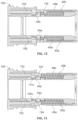
- FIGS. 11-13 show a sequence for loading the multi-fiber fiber optic connector 20 into a fiber optic adapter 150.
- the multi-fiber fiber optic connector 20 is grasped by the main grip-sleeve body 38 and is inserted into the port of the fiber optic adapter 150.
- FIG. 11 shows the multi-fiber fiber optic connector 20 and the fiber optic adapter 150 at the start of the insertion process.
- adapter latches 152 of the fiber optic adapter 150 engage the left and right adapter latch locks 40a, 40b and to push the adapter latch locks 40a, 40b rearwardly relative to the connector body 22 and the main grip-sleeve body 38 to the rearward position (see FIG. 12 ) where the left and right adapter latch receptacles 54a, 54a are no longer covered by the adapter latch locks 40a, 40b.
- the adapter latch receptacles 54a, 54b are uncovered, the adapter latches 152 can snap into the adapter latch receptacles 54a, 54b as shown a FIG. 12 .
- the adapter latches 152 After the adapter latches 152 snap into the left and right adapter latch receptacles 54a, 54b, the adapter latches 152 move inwardly so as to no longer be in contact with the left and right adapter latch locks 40a, 40b.
- the left and right grip-sleeve assembly springs 42a, 42b cause the left and right adapter latch locks 40a, 40b to move back to their forward positions relative to the main grip-sleeve body 38 (see FIG. 13 ).
- the cover portions of the left and right adapter latch locks 40a, 40b cover the adapter latches 152 within the left and right adapter latch receptacles 54a, 54b so as to prevent the adapter latches 152 from flexing outwardly to disengage from the adapter latch receptacles 54a, 54b.
- the adapter latches 152 are effectively locked within the left and right adapter latch receptacles 54a, 54b by the cover portions 134 of the left and right adapter latch locks 40a, 40b.
- the main grip-sleeve body 38 While the main grip-sleeve body 38 is in its forward position relative to the connector body 22 and the left and right adapter latch locks 40a, 40b are in their forward positions relative to the main grip-sleeve body 38 with the cover portions 134 covering the adapter latches 152 within the adapter latch receptacles 54a, 54b, the adapter latches 152 are prevented from disengaging from the adapter latch receptacles 54a, 54b and the multi-fiber fiber optic connector 20 is prevented from being removed from the fiber optic adapter 150.
- the main grip-sleeve body 38 is grasped and is pulled from its forward position (see FIG.
- the upper and lower keys 46a, 46b re mounted to slide respectively at the upper and lower major sides 48a, 48b of the connector body 22.
- the upper and lower keys 46a, 46b can be slid longitudinally along the longitudinal axis 52 relative to the connector body 22 between extended positions (see the upper key 46a at FIGS. 15 and 16 ) and retracted positions (see the lower key 46b at FIGS 15 and 16 ).
- the keys 46a, 46b are in the extended position, forward portions of the keys extend forwardly from the outer grip-sleeve assembly 36 a substantial distance along the forward portion of the connector body 22.
- the forward portions of the upper and lower keys 46a, 46b are preferably retracted at least substantially within the main grip-sleeve body 38.
- the projections 62 of the upper and lower keys 46a, 46b fit within the upper and lower key mounting slots 60a, 60b to provide sliding connections between the upper and lower keys 46a, 46b and the connector body 22.
- the upper and lower keys 46a, 46b can include front notches 154 that can be accessed with a tool to facilitate pulling the upper and lower keys 46a, 46b outwardly from the main grip-sleeve body 38 from the retracted position to the extended position.
- the main grip-sleeve body 38 can include internal structure for accommodating the upper and lower keys 46a, 46b and for allowing the upper and lower keys 46a, 46b to slide relative to the main grip-sleeve body 38.
- internal surfaces of the upper and lower major sides 110a, 110b of the main grip-sleeve body 38 can include key grooves 156 (see FIGS. 10 , 15 and 16 ) for receiving the upper and lower keys 46a, 46b.
- the key grooves 156 can include outer portions 157 and central portions 158.
- the central portions 158 have greater groove depths as compared to the outer portions 157.
- the greater groove depths provided by the central portions 158 provide clearance for allowing forward and rearward latches 160, 162 of the upper and lower keys 46a, 46b to deflect outwardly from the major upper and lower sides 48a, 48b of the connector body 22 to allow the latches to move into engagement with the upper and lower key latch receptacles 66a, 66b and to also disengage from the upper and lower key latch receptacles 66a, 66b of the connector body 22.
- each of the upper and lower keys 46a, 46b has an elongate length that extends along the longitudinal axis 52 when the keys 46a, 46b are mounted on the connector body 22.
- the forward and rearward latches 160, 162 of the keys 46a, 46b are aligned along the longitudinal axis 52 when the upper and lower keys 46a, 46b are mounted within the upper and lower key mounting slots 60a, 60b.
- the forward and rearward latches 160, 162 are longitudinally spaced from one another.
- the forward and rearward latches 160, 162 can be configured as resilient cantilevers having base ends 163 unitarily formed with main bodies of the upper and lower keys 46a, 46b.
- the flexible cantilevers can include catches 164 at free ends of the cantilevers.
- the catches 164 can include angled forward and rearward ramp surfaces 166 that can engage corresponding ramp surfaces 168 of the upper and lower key latch receptacles 66a, 66b to allow the forward and rearward latches 160, 162 to flex outwardly to engage or disengage from the upper and lower key latch receptacles 66a, 66b.
- the ramp surfaces 166, 168 engage and slide across each other causing the keys 46a, 46b to flex away from the connector body 22. This allows the catches 164 to ride over the ramps 168 and into or out of the latch receptacles 66a, 66b.
- the main grip-sleeve body 38 includes upper and lower key-latch blocking surfaces 170a, 170b that respectively block or cover the upper and lower key latch receptacles 66a, 66b when the main grip-sleeve body 38 is in the forward position relative to the connector body 22 (as shown at FIG. 15 ), and that are rearwardly offset from the key latch receptacle 66a, 66b when the main grip-sleeve body 38 is in the rearward position relative to the connector body 22 (as shown at FIG. 16 ).
- the latch blocking surfaces 170a, 170b oppose the catches 164 and prevents the catches 164 from disengaging from the latch receptacles 66a, 66b.
- the blocking surfaces 170a, 170b prevent the upper or lower keys 46a, 46b from being moved between the forward key position and the rearward position.
- the blocking surfaces 170a, 170b are offset from the latch receptacles 66a, 66b thereby enabling the keys 46a, 46b to be moved from the forward key position to the rearward key position by pushing the keys 46a, 46b rearwardly relative to the connector body 22, and also allow the keys 46a, 46b to be moved from the rearward key position to the forward key position by pulling the keys longitudinally forward relative to the connector body 22.
- the latches 160, 162 are free to flex outwardly away from the major sides 48a, 48b of the connector body 22 into the central portions 158 of the key grooves 156 so as to allow the catches 164 to clear the retaining portions of the latch receptacles 66a, 66b as the latches 160 or 162 selectively engage with or disengage from the latch receptacles 66a, 66b.
- a ramp effect provided by the ramped surfaces 166, 168 causes the latches 160, 162 to flex away from the connector body 22 when the latches 160, 162 are pushed or pulled while the main grip-sleeve body 38 is in the rearward position of FIG. 16 .
- the upper key 46a can be moved from the depicted forward key position to the rearward key position by retracting the main grip-sleeve body 38 as shown at FIG. 16 , and then pushing the upper key 46a rearwardly such that the catch 64 of the rear latch 162 disengages from the upper key latch receptacle 66a. Once the catch 164 of the rear latch 162 disengages from the latch receptacle 66a, the upper key 46a can be pushed rearwardly until the forward latch 160 engages with the latch receptacle 66a.
- the main grip-sleeve body 38 can be released and allow to return to the forward position relative to the connector body 22 by spring force provided by springs 42a, 42b such that the blocking surface 170a opposes the catch 164 of the forward latch 160 and locks the upper key 46a in the rearward key position.
- the lower key 46b can be moved from its forward position to its rearward position relative to the connector body 22 in a similar way as described above with respect to the upper key 46a.
- the lower key 46b is shown in the rearward key position. With the lower key 46b in the rearward position, the catch 164 of the forward latch 160 is in engagement with the lower latch receptacle 66b. With the main grip-sleeve body 38 in the forward position in FIG. 15 , the lower key latch blocking surface 170b opposes the catch 164 of the forward latch 160 to prevent the catch 164 from disengaging from the lower key latch receptacle 66b. By moving the main grip-sleeve body 38 to the rearward position of FIG. 16 , the lower key latch blocking surface 170b is preferably displaced from the catch 164 within the lower key latch receptacle 66b.
- the forward latch 160 is permitted to flex outwardly relative to the connector body 22. Therefore, with the main grip-sleeve body 38 in the retracted position of FIG. 16 , the lower key 46b can be pulled longitudinally in a forward direction which causes the forward latch 160 to flex outwardly and disengage from the lower latch receptacle 166b. Continued forward movement of the lower key 46b toward the forward key position brings the catch 164 of the rearward latch 162 into engagement with the lower key latch receptacle 66b.
- the catch 164 of the rearward latch 162 rides over the retaining features of the lower key latch receptacle 66b and nests within the pocket of the lower key latch receptacle 66b. Thereafter, the main grip-sleeve body 38 is released thereby allowing it to return by spring force to the forward position where the lower blocking surface 170b prevents the catch 164 of the rearward latch 162 from disengaging from the latch receptacle 66b.
- the upper key 46a can be moved from its rearward position to its forward position relative to the connector body 22 in a similar way as described above with respect to the lower key 46b.
- the main grip-sleeve body 38 is preferably manually held in the rearward position of FIG. 16 against the bias of the left and right grip-sleeve assembly springs 42a, 42b.
- the main grip-sleeve body 38 can be released thereby allowing the springs 42a, 42b to return the main grip-sleeve body 38 to its forward position of FIG. 15 where the blocking surfaces 170a, 170b prevent the latches 160, 162 from disengaging from their corresponding latch receptacles 66a, 66b.
- the upper key 46a When the upper key 46a is in the forward key position, the upper key 46a is not visible through the upper viewing window 118a. In contrast, when the upper key 46a is in the rearward key position, the upper key 46a is visible through the upper viewing window 118a. It will be appreciated that the upper viewing window 118a is positioned to be located outside the fiber optic adapter 150 when the multi-fiber fiber optic connector 20 is loaded within the fiber optic adapter 150. Therefore, even when the multi-fiber fiber optic connector 20 is secured within the fiber optic adapter 150, the upper viewing window 118a allows an operator to identify the position of the upper key 46a.
- the lower key 46b When the lower key 46b is in the rearward key position as shown at FIGS. 15 and 16 , the lower key 46b is visible through the lower viewing window 118b.
- the lower viewing window 118b is positioned so as to be located outside the fiber optic adapter 150 when the multi-fiber fiber optic connector 120 is secured within the port of the fiber optic adapter 150. Therefore, the lower viewing window 118b allows the position of the lower key 46b to be visually determined even when the multi-fiber fiber optic connector 20 is secured within the fiber optic adapter 150.
- the lower key 46b When the lower key 46b is in the forward key position, the lower key 46b is not visible through the lower viewing window 118b. Therefore, the presence or absence of the lower key 46b at the lower viewing window 118b allows for the position of the lower key 46b to be determined visually even when the multi-fiber fiber optic connector 20 is positioned within the fiber optic adapter 150.
- the multi-fiber fiber optic connector 20 includes features for allowing the rear spring stop 32 to be disengaged from the connector body 22.
- the cover portions 134 of the left and right adapter latch locks 40a, 40b can include openings 172 configured for receiving a tool.
- the openings 172 are brought into alignment with the left and right openings 104a, 104b defined through the minor sides of the connector body 22.
- the retention tabs 102 of the rear spring stop 32 fit within the openings 104a, 104b.
- a tool can be inserted through the openings 172 and used to disengage the retention tabs 102 of the latching arms 100a, 100b from the openings 104a, 104b to allow the rear spring stop 32 to be removed from the interior of the connector body 22.
- the pin retention structure 92 of the ferrule assembly 28 includes structure for selectively retaining the ferrule alignment pins 88a, 88b within the alignment pin openings 90a, 90b. It is preferred for the structure to be accessible from outside the multi-fiber fiber optic connector 20 to allow the ferrule alignment pins 88a, 88b to be released from the alignment pin openings 90a, 90b to convert the multi-fiber fiber optic connector from a male configuration to a female configuration.
- the pin retention arrangement 92 preferably includes retaining elements or structures that are movable between retaining positions and release positions.
- retaining structures can include resilient or spring-like structures that are inherently spring biased toward the retaining positions that can be moved to the released positions by means such as a tool.
- the tool can be inserted into the multi-fiber fiber optic connector 20 without requiring disassembly of the multi-fiber fiber optic connector 20.
- FIGS. 17-20 show an example configuration for the pin retention structure 92.
- the pin retention structure 92 is adapted to secure the ferrule alignment pins 88a, 88b within the alignment pin openings 90a, 90b, and can be released to allow removal of the alignment pins 88a, 88b from the alignment pin openings 90a, 90b.
- the pin retention structure 92 has a metal construction such as a sheet-metal construction.
- the pin retention structure 92 includes left and right resilient spring elements 174a, 174b that in certain examples include pin retaining portions 175a, 175b that are movable between pin retaining positions (see solid line at FIG. 20 ) and pin release positions (see phantom line at FIG. 20 ).
- the pin retaining portions 175a, 175b fit within the circumferential retention grooves 94 of the ferrule alignment pins 88a, 88b to prevent the ferrule alignment pins 88a, 88b from being removed from the alignment pin openings 90a, 90b.
- the pin release positions the pin retaining portions 175a, 175b are displaced the circumferential retention grooves 94 of the ferrule alignment pins 88a, 88b such that the ferrule alignment pins 88a, 88b can be removed from the alignment pin openings 90a, 90b without interference from the pin retaining portions 175a, 175b.
- the left and right resilient spring elements 174a, 174b spring bias the pin retaining portions 175a, 175b in a direction toward the pin retaining positions.
- the pin retention structure 92 includes a main body 220 having a front side 222 and a rear side 224.
- the ferrule boot 96 can extend axially through an open central region 225 of the main body 220.
- the left and right resilient spring elements 174a, 174b are depicted as cantilever springs having lengths that extend along and are generally parallel to the longitudinal axis 52 of the connector 20 (see FIG. 8 ) when the connector is assembled.
- the resilient spring elements 174a, 174b include base ends 226 (see FIG. 19 ) unitarily formed with the main body 220 at the rear side 224 of the main body 220, and free ends 228 (see FIG. 19 ) located at the front side 222 of the main body 220.
- the pin retaining portions 175a, 175b are depicted as inward projections/tabs at the free ends 228 of the resilient spring elements 174a, 174b.
- the base ends 226 form primary resilient flex locations for the resilient spring elements 174a, 174b, although the spring elements 174a, 174b also flex along their lengths.
- the main body 220 defines left and right notches 230a, 230b (see FIG. 17 ) that co-axially align with the alignment pin openings 90a, 90b when the connector 20 is assembled.
- the left and right notches 230a, 230b are defined at the front side 222 of the main body 220 and are adapted for receiving rear ends of the pins 88a, 88b when the pins 88a, 88b are installed in the ferrule 80.
- the left and right notches 230a, 230b are positioned on opposite sides of the open central region 225 of the main body 220.
- the pin retaining portions 175a, 175b align with the left and right notches 230a, 230b and are positioned laterally outside the notches 230a, 230b.
- the spring elements 174a, 174b include stop portions 177a, 177b (see FIG.
- the left and right spring elements 174a, 174b include release tabs 179a, 179b at the free ends 228.
- the release tab 179a of the left resilient spring element 174a projects below the main body 220 and the release tab 179b of the right resilient spring element 174b projects above the main body 220.
- the connector body 22 defines left and right pin release access openings 184a, 184b (see FIG. 8 ) that are respectively defined through the minor sides 50a, 50b of the connector body 22 at the pockets of the left and right adapter latch receptacles 54a, 54b.
- the left and right access openings 184a, 184b can be accessed by manually pulling back the main grip-sleeve body 38 against the bias of the springs 42a, 42b from the forward position to the rearward position.
- the pin release access openings 184a, 184b are exposed. At least portions of the release tabs 179a, 179b overlap or align with the release pin openings 184a, 184b.
- a release tool can be inserted through the openings 184a, 184b to move the pin retaining portions 175a, 175b to the pin release positions so that the ferrule alignment pins 88a, 88b can be removed from their corresponding alignment openings 90a, 90b by pulling the pins 88a, 88b forwardly from the openings 90a, 90b.
- the alignment pins 88a, 88b have inner sides 178 that face toward each other and toward the central longitudinal axis 52 of the fiber optic connector, and outer sides 180 that face away from each other and away from the longitudinal axis 52.
- the pin retaining portions 175a, 175b of the resilient spring elements 174a, 174b insert within the circumferential grooves 94 of the alignment pins 88 at the outer sides 180 of the alignment pins 88a, 88b.
- a tool or tools can be used from outside the multi-fiber fiber optic connector 20 to apply release forces to the tabs 179a, 179b of the left and right resilient elements 174a, 174b to move the retaining portions 175a, 175b from the retaining positions to the release positions.
- the main grip-sleeve body 38 is retracted and a tool is inserted through the right pin release access opening 184b to engage the tab 179a of the left resilient spring element 174a and push the left spring retaining portion 175a outwardly from the left ferrule alignment pin 88a to the pin release position such that the ferrule alignment pin 88a can be removed from the opening 90a.
- the tool shown schematically at FIG.
- the right alignment pin 88b can be withdrawn from the right alignment pin opening 90b.
- the tool (shown schematically at FIG. 17 by arrow 181b) travels from the left pin release opening 184a over the top side of the main body 220 of the pin retention arrangement 92 and across the width of the multi-fiber fiber optic connector 20 to the right release tab 179b.
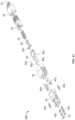
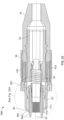
- FIGS. 21-26 show another multi-fiber fiber optic connector 320 in accordance with the principles of the present disclosure.
- the multi-fiber connector 320 has the same construction and arrangement as the multi-fiber fiber optic connector 20, except the multi-fiber fiber optic connector 320 includes a modified pin retention structure 390 for retaining the alignment pins 88a, 88b within the alignment pin openings 90a, 90b of the multi-fiber ferrule 80.
- the pin retention structure 390 includes a main body 380 that is held against the back end of the ferrule 80 by the ferrule spring 30.
- the main body 380 can have a molded, dielectric (e.g., plastic) construction.
- the main body 380 is generally U-shaped and defines an open central region 370 through which the ferrule boot 96 extends (see FIG. 22A ).
- the main body 380 includes a front side 381 and a rear side 382.
- the main body 380 defines left and right pin openings 383a, 383b that extend axially through the main body 380 from the front side 381 to the rear side 382.
- the pin openings 383a, 383b are on opposite sides of the open central region 370.
- the left and right pin openings 383a, 383b are adapted to receive rear ends of the ferrule alignment pins 88a, 88b.
- Left and right side notches 384a, 384b be are provided adjacent the left and right pin openings 383a, 383b.
- Left and right tool stops 385a, 385b are provided within the left and right side notches 384a, 384b outside the left and right pin openings 383a, 383b.
- the left and right notches 384a, 384b are adapted to provide upper and/or lower open tool paths 385 that extend laterally through the left and right sides of main body 380 and laterally over or under the ferrule alignment pins 88a, 88b when the ferrule alignment pins 88a, 88b are received within the pin openings 383a, 383b.
- the left and right notches 384a, 384b align with the left and right pin release access openings 184a, 184b by moving the ferrule 80 to a rearward position relative to the connector body 22 against the bias of the ferrule spring 30.
- the front side 381 of the main body 380 defines a U-shaped channel 371 for receiving a U-shaped alignment pin retainer 372.
- the alignment pin retainer 372 can be a metal wire forming a clip.
- the alignment pin retainer 372 includes a base portion 373 that extends across the open central region 370 and across a width of the fiber optic connector 320.
- the alignment pin retainer 372 includes left and right resilient spring elements 374a, 374b that correspond to each of the left and right pin openings 383a, 383b.
- the resilient spring elements 374a, 374b are formed as legs that project from opposite ends of the base portion 373.
- the resilient spring elements 374a, 374b are resilient cantilevers having base ends integral with the base portion 373 and free ends spaced from the base portion 373.
- the resilient spring elements 374a, 374b have lengths that are generally perpendicular to the longitudinal axis 52 and to the ferrule alignment pins 88a, 88b.
- the rear ends of the pins 88a, 88b fit within the left and right pin openings 383a, 383b of the main body 380 of the pin retention structure 390, and pin retention portions of the resilient spring elements 374a, 374b fit within the circumferential retention grooves 94 of the pins 88a, 88b.
- the resilient spring elements 374a, 374b fit within the circumferential grooves 94 at the inner sides 178 of the alignment pins 88a, 88b.
- the resilient spring elements 374a, 374b are spring biased toward pin retaining positions within the grooves 94 at the inner sides 178 of the pins 88a, 88b.
- the resilient spring elements 374a, 374b are moved from the pin retaining positions to the pin release positions by flexing the resilient spring elements 374a, 374b away from the pins 88a, 88b inwardly toward the central longitudinal axis 52.
- the pins 88a, 88b can be pulled forwardly from the alignment pin openings 90a, 90b to remove the pins 88a, 88b from the ferrule 80.
- the ferrule 80 is moved to the rearward position relative to the connector body 22 to bring the right side notch 384b into alignment with the right pin release access opening 184b of the connector body.
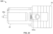
- the main grip-sleeve body 38 is also moved to its rearward position relative to the connector body 22 to expose the right pin release access openings 184b (see FIG. 23 ).
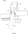
- a tool 377 (see FIG. 24 ) is then used to push the right resilient spring element 374b inwardly to the pin release position by inserting the tool through the right pin release access opening 184b and through the open lateral tool paths 387 of the right side notch 384b to engage the right resilient spring element 374b.
- the tool 377 can have a forked end with extensions 389 that extend along/through the tool paths 385 above and below the alignment pin 88b to reach the right resilient spring element 374b at the inner side 178 of the pin 88b.
- the right tool stop 385b limits the insertion depth of the tool 377.
- left pin 88a can be removed in a similar way by inserting the tool 377 through the left pin release access opening 184a and the tool paths 387 of the left side notch 384a to move the left resilient spring element 374a to the pin release position thereby allowing the left pin 88a to be pulled forwardly from the ferrule 80.
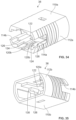
- FIGS. 36 and 37 show another multi-fiber fiber optic connector 400 in accordance with the principles of the present disclosure. Referring concurrently to FIGS. 36 and 37 , certain components are described above, and thus, are not necessarily described further.
- the multi-fiber fiber optic connector 400 has the same construction and arrangement as the multi-fiber fiber optic connectors described above (e.g., connectors 20 and 320), except the connector 400 includes anther configuration of a pin retention structure 402 for retaining the alignment pins 88b within the alignment pin openings 90b of the multi-fiber ferrule 80.
- the pin retention structure 402 includes a main body 404 that is held against the back end of the ferrule 80 by the ferrule spring 30.
- the main body 404 can have a molded, dielectric (e.g., plastic) construction.
- the main body 404 may be generally U-shaped such that the ferrule boot 96 can extend therein.
- the main body 404 defines pin openings 406b that extend axially through the main body 404 from the front side.
- the pin openings 406b are on opposite sides of the ferrule boot 96 (the left side pin opening 406a is not illustrated in FIG. 36 ) and are adapted to receive rear ends of the ferrule alignment pins 88b.
- the main body 404 is sized and shaped to support an alignment pin retainer 408b (shown in FIG. 37 ).
- the alignment pin retainer 408b can be a substantially U-shaped metal wire and include a base 410 with two opposing resilient spring elements 412 extending therefrom.
- the resilient spring elements 412 are formed as generally L-shaped legs that are resilient cantilevers and with lengths that are substantially parallel to the longitudinal axis 52 (shown in FIG. 7 ) and to the ferrule alignment pin 88b.
- the rear end of the pin 88b fits within the pin opening 406b of the main body 404 of the pin retention structure 402, and pin retention portions of the resilient spring elements 412 fit within the circumferential retention groove 94 of the pin 88b.
- the resilient spring elements 412 fit within the circumferential groove 94 at two different locations approximately 180° apart from one another (e.g., at a top and a bottom location on the ferrule alignment pin 88b) so as to retain the ferrule alignment pin 88b to the pin retention structure 402.
- the resilient spring elements 412 are spring biased toward pin retaining positions within the groove 94 of the pin 88b.
- the resilient spring elements 412 are moved from the pin retaining position (shown in FIG. 37 ) to the pin release position by flexing the resilient spring elements 412 away from the pin 88b.
- the resilient spring elements 412 are flexed away from the pin 88b and in a direction illustrated by arrows 414 that are substantially orthogonal to the longitudinal axis 52.
- the pin 88b can be pulled forwardly from the alignment pin opening 90b to remove the pin 88b from the ferrule 80.
- the main body 404 may have a tool path opening 418b defined on the sides so that the tool 416 can reach the alignment pin retainer 408a.
- the sides of the main body 404 may be substantially open so as to enable access to the alignment pin retainer 408 by the tool 416.
- the access to the pin retainer 408 is on a side of the main body 404 that is substantially orthogonal to the front of the main body 404 that has the opening 406b that the pin 88b extends through.
- the tool 416 can have a wedge shaped end that pushes the resilient spring element 412 away from each other. Once the tool 416 has moved the resilient spring elements 412 to the pin release position, the pin 88b can be pulled forwardly from the ferrule 80.
- the alignment pin is inserted rearwardly into the alignment pin openings.
- the rear end of the alignment pin engages the pin retaining portion of the corresponding resilient spring element thereby forcing the pin retaining portion to flex from the pin retaining position to the pin release position.
- a tool can be used to move the pin retaining portion to the pin release position.
- the pin retaining portion When the circumferential groove of the alignment pin moves into alignment with the pin retaining portion of the resilient spring element, the pin retaining portion snaps into the circumferential groove and thereby moves from pin release positions to the pin retaining positions such that the alignment pin is locked/retained within the alignment pin opening.
- the movement of the resilient spring element from the pin retaining position to the pin release position is caused by the inherent elasticity/resiliency of the resilient spring element.
- a tool can be used to move the pin retaining portion from the pin retaining position to the pin release position. With the pin retaining portion held in the release position, the alignment pin can be pulled forwardly out of the alignment pin opening.
- the resilient spring elements of the pin retention structures disclosed herein include resilient cantilever arms having lengths that extend between base ends and opposite free ends.
- the resilient cantilever arms are oriented with their lengths parallel to the alignment pins.
- the resilient cantilever arms are oriented with their lengths perpendicular to the alignment pins.
- the resilient cantilever arms are oriented parallel to the alignment pins and include release tabs that extend higher or lower than the alignment pins.
- the resilient cantilever arms are oriented perpendicular relative to the alignment pins and the free end portions of the resilient cantilever arms project higher or lower than the alignment pins.
- the ferrule alignment pins of the type disclosed herein include inner sides that face toward each other and toward a central longitudinal axis of the fiber optic connector, and also include outer sides that face away from each other and away from the central longitudinal axis of the fiber optic connector.
- the pin retaining portions of the resilient spring elements fit within the circumferential grooves of the alignment pins at the inner sides of the alignment pins, and are moved from the pin retaining positions to the pin release positions by flexing the resilient spring elements inwardly toward the central longitudinal axis of the fiber optic connector.
- the pin retaining portions of the resilient spring elements fit within the circumferential grooves of the alignment pins at the outer sides of the alignment pins, and are moved from the pin retaining positions to the pin release positions by flexing the resilient spring elements outwardly away from the central longitudinal axis of the fiber optic connector.
- the pin retaining portions of the resilient spring elements fit within the circumferential grooves of the alignment pins at two or more locations, and are moved from the pin retaining position to the pin release positions by flexing the resilient spring elements outwardly away from the elongated alignment pin.
- the two or more locations can be at a top and a bottom location on the alignment pin, or the two or more locations can be at a left and a right location on the alignment pin.
- each alignment pin can have its own separate pin retaining portion.
- a tool can be used to move each resilient spring element from the pin retaining position to the pin release position without requiring the fiber optic connector to be disassembled.
- tool access openings for access the resilient spring elements with a tool are defined though minor sides of the connector body of the fiber optic connector.
- the tool access openings are exposed when the outer grip-sleeve is in a rear position relative to the connector body, and are covered when the outer grip-sleeve is in a forward position relative to the connector body.
- open tool paths exists within the connector body between the side tool access openings and the resilient spring elements.
- the open tool paths can extend above or below only one of the alignment pins.
- the open tool path corresponding to a left one of the resilient spring elements extends through the left side of the connector body and over or under the left alignment pin before reaching the left one of the resilient spring elements.
- the open tool path corresponding to a right one of the resilient spring elements extends through the right side of the connector body and over or under the right alignment pin before reaching the right one of the resilient spring elements.
- the open tool paths can extend above or below both of the left and right alignment pins.
- the open tool path corresponding to a left one of the resilient spring elements extends through the right side of the connector body and across the width of the connector body over or under the right and left alignment pins before reaching the left one of the resilient spring elements.
- the open tool path corresponding to a right one of the resilient spring elements extends through the left side of the connector body and across the width of the connector body over or under the left and right alignment pins before reaching the right one of the resilient spring elements.
Landscapes
- Physics & Mathematics (AREA)
- General Physics & Mathematics (AREA)
- Optics & Photonics (AREA)
- Mechanical Coupling Of Light Guides (AREA)
Abstract
Description
- This application is being filed on June 19, 2019 as a PCT International Patent Application and claims the benefit of
U.S. Patent Application Serial No. 62/687,163, filed on June 19, 2018 - The present disclosure relates generally to fiber optic connectors. More particularly, the present disclosure relates to multi-fiber fiber optic connectors.
- A multi-fiber fiber optic connector, for example an MPO (Multi-Fiber Push On) connector, typically includes a connector body supporting a multi-fiber ferrule at a front end and a connector boot at a rear end. Typically, an outer release-sleeve (i.e., a grip-sleeve) is mounted on the connector body. The outer release-sleeve is slidable relative to the connector body and is spring biased toward a forward position. When the multi-fiber fiber optic connector is inserted into a corresponding fiber optic adapter, the release-sleeve covers latches of the fiber optic adapter to retain the latches in latched positions relative to the connector body such that the fiber optic connector is prevented from being withdrawn from the adapter. By pulling back on the release-sleeve, the release-sleeve is displaced from the latches of the fiber optic adapter such that the latches can flex outwardly to unlatched positions in which multi-fiber fiber optic connector can be withdrawn from the fiber optic adapter.
- An MPO connector can either be male or female. A male MPO connector includes two alignment pins that project forwardly from the multi-fiber ferrule of the connector. A female MOP connector includes alignment openings within the multi-fiber ferrule adapted to receive the alignment pins of a mating male MPO connector. The ability to change genders between male and female MPO connectors in the field is desirable.
- MPO connectors typically include a key integrated with the connector housing for determining the polarity of the fiber optic connectors. Depending on the fiber optic system into which the MPO connector is intended to be incorporated, it may be required to have a key on either a bottom side or a top side of the fiber optic connector.
- One aspect of the present disclosure relates to a multi-fiber fiber optic connector having a connector body with a front end. The multi-fiber fiber optic connector also includes a multi-fiber ferrule positioned at the front end of the connector body. The fiber optic connector further includes an outer grip-sleeve assembly that mounts on the connector body. The outer grip-sleeve assembly includes a main grip-sleeve body and two separate adapter latch locks mounted at opposite sides of the main grip-sleeve body. The adapter latch locks are slidably movable relative to the main grip-sleeve body and are independently movable relative to one another. Separate springs bias the adapter latch locks toward forward positions relative to the main grip-sleeve body, and also bias the main grip-sleeve body toward a forward position relative to the connector body.
- Another aspect of the present disclosure relates to a multi-fiber fiber optic connector including a connector body having a front end. The fiber optic connector also includes a multi-fiber ferrule mounted at the front end of the connector body. The fiber optic connector also includes an outer grip-sleeve that mounts on the connector body. The outer grip-sleeve is mounted to slide longitudinally relative to the connector body and is spring biased toward a forward position relative to the connector body. The fiber optic connector further includes keys slidably mounted at top and bottom sides of the connector body. The keys are each slidably movable relative to the connector body between an extended position and a retracted position. Each of the keys includes first and second latches. The connector body defines latch receptacles that are defined at the top and bottom sides of the connector body and that are covered by the outer grip-sleeve. The outer grip-sleeve includes latch blocking surfaces that cover the latch receptacles to provide key latch retention when the outer grip-sleeve is in the forward position. When the outer grip-sleeve is in a rearward position relative to the connector body, the latch blocking surfaces are offset from the latch receptacles to allow key latch disengagement from the latch key receptacles. When the keys are in the extended positions, the first key latches engage with the key latch receptacles. In contrast, when the keys are in the retracted positions, the second key latches engage with the latch receptacles.
- Another aspect of the present disclosure relates to a fiber optic connector including a connector body having a front end. The fiber optic connector also includes a multi-fiber ferrule positioned at the front end of the connector body. The fiber optic connector further includes a grip-sleeve mounted on the connector body. The fiber optic connector includes alignment pins mountable within alignment pin openings defined by the multi-fiber ferrule. The alignment pins include circumferential retention grooves adjacent rear ends of the alignment pins. The fiber optic connector includes an alignment pin retention structure including resilient spring elements. The resilient spring elements include pin retaining portions that are moveable between pin retaining positions and pin release positions, and that are spring biased toward the pin retaining positions. In one example, the pin retaining portions fit within the circumferential grooves at inner sides of the alignment pins, and are moved from the pin retaining positions to the pin release positions by flexing the pin retaining portions inwardly toward a central axis of the fiber optic connector. In another example, the pin retaining portions fit within the circumferential grooves at outer sides of the alignment pins, and are moved from the pin retaining positions to the pin release positions by flexing the pin retaining portions outwardly away from the central axis of the fiber optic connector. In certain examples, a tool can be used to move each resilient spring element from the pin retaining position to the pin release position without requiring the fiber optic connector to be disassembled.
- A variety of advantages of the disclosure will be set forth in part in the description that follows, and in part will be apparent from the description, or may be learned by practicing the various aspects of the present disclosure. It is to be understood that both the forgoing general description and the following detailed description are exemplary and explanatory only and are not restrictive of the broad inventive concepts upon which the examples are based.
-
-
FIG. 1 is a front, top, left perspective view of a multi-fiber fiber optic connector in accordance with the principles of the present disclosure; -
FIG. 2 is a front, bottom, right perspective view of the multi-fiber fiber optic connector ofFIG. 1 ; -
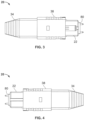
FIG. 3 is a top view of the multi-fiber fiber optic connector ofFIG. 1 ; -
FIG. 4 is a bottom view of the multi-fiber fiber optic connector ofFIG. 1 ; -
FIG. 5 is a right side view of the multi-fiber fiber optic connector ofFIG. 1 ; -
FIG. 6 is a front view of the multi-fiber fiber optic connector ofFIG. 1 ; -
FIG. 7 is an exploded view of the multi-fiber fiber optic connector ofFIG. 1 ; -
FIG. 8 is a cross-sectional view taken along section line 8-8 ofFIG. 6 ; -
FIG. 9 is a cross-sectional view cut along a vertical plane through an outer grip-sleeve assembly of the multi-fiber fiber optic connector ofFIG. 1 ; -
FIG. 10 is a cross-sectional view cut along a horizontal plane that bisects a main grip-sleeve body of the outer grip-sleeve assembly of the multi-fiber fiber optic connector ofFIG. 1 ; -
FIGS. 11-13 depict a progression of views showing the multi-fiber fiber optic connector ofFIG. 1 being inserted into an adapter; -
FIG. 14 depicts a connector body and upper and lower keys of the multi-fiber fiber optic connector ofFIG. 1 ; -
FIG. 15 is a cross-sectional view showing the upper and lower keys of the multi-fiber fiber optic connector ofFIG. 1 latched relative to the connector body with the grip-sleeve in a forward position relative to the connector body; -
FIG. 16 shows the assembly ofFIG. 15 with the grip-sleeve in a rearward position relative to the connector body; -
FIG. 17 is a front view of a pin retainer for retaining alignment pins of the multi-fiber fiber optic connector ofFIG. 1 ; -
FIG. 18 is a right side view of the pin retainer ofFIG. 17 ; -
FIG. 19 is a top view of the pin retainer ofFIG. 17 ; -
FIG. 20 shows the pin retainer ofFIG. 17 with retaining portions of the pin retainer positioned within retention grooves of the alignment pins of the multi-fiber fiber optic connector ofFIG. 1 ; -
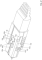
FIG. 21 is an exploded view of another multi-fiber fiber optic connector in accordance with the principles of the present disclosure; -
FIG. 22 is a cross-sectional view taken lengthwise through the multi-fiber fiber optic connector ofFIG. 21 ; -
FIG. 22A is an enlarged view of a portion ofFIG. 22 ; -
FIG. 23 is a side view of a portion of the multi-fiber fiber optic connector ofFIG. 21 ; -
FIG. 24 shows a tool being used to disengage a pin retention structure of the multi-fiber fiber optic connector ofFIG. 21 ; -
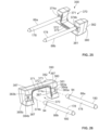
FIG. 25 shows a pin retention structure of the multi-fiber fiber optic connector ofFIG. 21 , the pin retention structure is shown interlocked with alignment pins of the multi-fiber fiber optic connector ofFIG. 21 ; -
FIG. 26 shows the pin retention structure ofFIG. 25 with the alignment pins disengaged from the pin retention structure; -
FIG. 27 is a partial cross-sectional view of the multi-fiber fiber optic connector ofFIG. 1 ; -
FIG. 28 is a perspective view of one of the adapter latch locks of the multi-fiber fiber optic connector ofFIG. 1 ; -
FIG. 29 is another perspective view of the adapter latch lock ofFIG. 28 ; -
FIG. 30 is a perspective view of one of the keys of the multi-fiber fiber optic connector ofFIG. 1 ; -
FIG. 31 is another perspective view of the key ofFIG. 30 ; -
FIG. 32 is a perspective view of one of the connector body of the multi-fiber fiber optic connector ofFIG. 1 ; -
FIG. 33 is another perspective view of the connector body ofFIG. 32 ; -
FIG. 34 is a perspective view of the main grip-sleeve body multi-fiber fiber optic connector ofFIG. 1 ; -
FIG. 35 is another perspective view of the main grip-sleeve body ofFIG. 34 ; -
FIG. 36 is a partial cross-sectional view taken lengthwise through another multi-fiber fiber optic connector in accordance with the principles of the present disclosure; and -
FIG. 37 is a side view of a pin retention structure of the multi-fiber fiber optic connector ofFIG. 36 , the pin retention structure is shown interlocked with alignment pins. -
FIGS. 1-7 depict a multi-fiberfiber optic connector 20 in accordance with the principles of the present disclosure. The multi-fiberfiber optic connector 20 has enhanced functionality at least relating to the ability to easily change polarity, the ability to easily change gender, and the ability to operate the multi-fiberfiber optic connector 20 as a true push-pull fiber optic connector (e.g., a true push-pull MPO connector). A true push-pull fiber optic connector is a connector in which the outer grip sleeve can be grasped during both insertion of the connector into a fiber optic adapter and during removal of the connector from the fiber optic adapter. - As best shown at
FIG. 7 , the multi-fiberfiber optic connector 20 includes aconnector body 22 having afront end 24 and an oppositerear end 26. Aferrule assembly 28 of the multi-fiberfiber optic connector 20 is configured to mount within an interior of theconnector body 22. Aspring 30 of the multi-fiberfiber optic connector 20 is configured to bias theferrule assembly 28 in a forward direction relative to theconnector body 22. The multi-fiberfiber optic connector 20 also includes arear spring stop 32 configured to mount within therear end 26 of theconnector body 22. Therear spring stop 32 is configured to retain thespring 30 within theconnector body 22. Arear connector boot 34 is configured to mount to a rear end of therear spring stop 32. Therear connector boot 34 can have a flexible configuration for providing optical fiber bend radius protection and strain relief at the rear end of the multi-fiberfiber optic connector 20. It will be appreciated that in use, theconnector 20 mounts at the end of a fiber optic cable, and theboot 34 preferably provides flexible support where the cable enters the rear of the connector. The multi-fiberfiber optic connector 20 further includes an outer grip-sleeve assembly 36 configured to mount over theconnector body 22. The outer grip-sleeve assembly 36 includes a main grip-sleeve body 38 and separate left and rightadapter latch locks sleeve assembly 36 in a forward direction when the outer grip-sleeve assembly 36 is mounted on theconnector body 22. The left and right grip-sleeve assembly springs 42a, 42b respectively mount within left andright spring grooves FIG. 8 ) defined by theconnector body 22. The multi-fiberfiber optic connector 20 further includes upper andlower keys major sides front end 24 of theconnector body 22. - Referring to
FIGS. 32 and 33 , the upper and lowermajor sides connector body 22 extend lengthwise between thefront end 24 and therear end 26 of the connector body. Theconnector body 22 also includes opposite left and rightminor sides major sides rear ends connector body 22 defines alongitudinal axis 52 that extends between the front andrear ends minor sides adapter latch receptacles minor sides right spring grooves right spring grooves right spring grooves rear ends FIG. 8 ). In certain examples, the front ends 56 of thespring grooves spring grooves - The
connector body 22 also includes structure for accommodating the upper andlower keys lower keys major sides connector body 22. It is preferred for the upper andlower keys longitudinal axis 52 relative to theconnector body 22 between forward and rearward positions. To accommodate sliding movement of the upper andlower keys connector body 22 defines upper and lower longitudinalkey mounting slots FIGS. 14-16 ,32 and 33 ) that extend longitudinally along theconnector body 22 in a rearward direction from thefront end 24 of theconnector body 22. In certain examples, thekey mounting slots FIG. 32 ) adapted to receive mating projections 62 (seeFIG. 30 ) of the upper andlower keys projections 62 can have complimentary cross-sections with the transverse cross-sectional profiles of thekey mounting slots FIGS. 30 and 31 ). Theconnector body 22 further includes upper and lower sets ofkey guides major sides FIGS. 14 ,32 and 33 ). The key guides 64a, 64b are configured as guiderails that have lengths that extend along thelongitudinal axis 52. The key guides 64a, 64b include opposing surfaces between which the upper andlower keys connector body 22 further includes upper and lowerkey latch receptacles FIGS. 14-16 ,32 and 33 ). - The
connector body 22 further includes exterior structures for retaining the outer grip-sleeve assembly 36 on theconnector body 22 when the outer grip-sleeve assembly 36 has been installed over theconnector body 22. For example, the upper and lowerkey guides rear ends 68 which include rearwardly facing stop surfaces adapted to stop forward movement of the outer grip-sleeve assembly 36 relative to theconnector body 22 once the outer grip-sleeve assembly 36 is mounted on the connector body 22 (seeFIG. 27 ). Additionally, theconnector body 22 includes left and right side stops 70a, 70b (seeFIGS. 27 ,32 and 33 ) near therear end 26 of theconnector body 22. The left and right side stops 70a, 70b include forwardly facing stop surfaces that are adapted to stop movement of the outer grip-sleeve assembly 36 in the rearward direction when the outer grip-sleeve assembly 36 is mounted on theconnector body 22. - Referring to
FIG. 7 , theferrule assembly 28 of the multi-fiberfiber optic connector 20 includes amulti-fiber ferrule 80 that is positioned within theconnector body 22 adjacent thefront end 24 of the connector body when theferrule assembly 28 has been installed within theconnector body 22. Themulti-fiber ferrule 80 has an elongate transverse cross-sectional profile defining perpendicular major andminor dimensions 82, 84 (seeFIGS. 6 and7 ). With themulti-fiber ferrule 80 installed in theconnector body 22, themajor dimension 82 extends between the left and rightminor sides connector body 22 and theminor dimension 84 extends between the upper and lowermajor sides FIG. 6 ). Themulti-fiber ferrule 80 defines a plurality of fiber openings 86 (seeFIG. 8 ) for receiving optical fibers corresponding to a fiber optic cable which is terminated by the multi-fiberfiber optic connector 20. At least some of thefiber openings 86 are arranged in a row that extends along themajor dimension 82 of themulti-fiber ferrule 80. - The
multi-fiber ferrule 80, when installed in theconnector body 22, is preferably movable relative to the connector body along thelongitudinal axis 52 and is spring biased toward a forward position relative to theconnector body 22 by the ferrule biasing spring 30 (seeFIG. 8 ). Referring again toFIG.7 , theferrule assembly 28 also includes left and rightferrule alignment pins alignment pin openings fiber optic connector 20 is configured as a male connector. When theferrule alignment pins alignment pin openings ferrule alignment pins alignment pin openings multi-fiber ferrule 80. In certain examples, thepin retention structure 92 is held against the back end of theferrule 80 by theferrule biasing spring 30. In certain examples, theferrule alignment pins FIG. 20 ) adjacent rear ends of theferrule alignment pins pin retention structure 92 to retain theferrule alignment pins alignment pin openings fiber optic connector 20 is configured as a female fiber optic connector, theferrule alignment pins alignment pin openings alignment pin openings ferrule assembly 28 additionally includes aferrule boot 96 that is assembled within the rear end of themulti-fiber ferrule 80. Theferrule boot 96 is configured for receiving the optical fibers that are routed into themulti-fiber ferrule 80 from the cable to which themulti-fiber connector 20 is terminated. For example, theferrule boot 96 can define a through passage for receiving optical fibers routed into themulti-fiber ferrule 80 from the optical cable to which the multi-fiberfiber optic connector 20 is terminated/mounted. - It will be appreciated that the
ferrule assembly 28, theferrule biasing spring 30 and therear spring stop 32 are all loaded into theconnector body 22 through therear end 26 of theconnector body 22. Theferrule biasing spring 30 has a front end that seats against thepin retention structure 92 and a rear end that abuts against a spring seat 98 of therear spring stop 32. As shown atFIG. 8 , therear spring stop 32 includes left and right latchingarms retention tabs 102 that snap within corresponding left andright openings minor sides connector body 22 when therear spring stop 32 is loaded into theconnector body 22. The left andright openings spring grooves multi-fiber ferrule 80 is biased to the forward position by theferrule biasing spring 30, afront shoulder 106 of themulti-fiber ferrule 80 abuts against astop structure 108 within theconnector body 22. Theferrule assembly 28 and theferrule biasing spring 30 are thus captured within theconnector body 22 between thestop structure 108 and therear spring stop 32. - The main grip-
sleeve body 38 of the outer grip-sleeve assembly 36 includes upper and lowermajor sides FIGS. 34 and 35 ) that respectively oppose the upper and lowermajor sides connector body 22 when the main grip-sleeve body 38 is mounted on the connector body 22 (seeFIGS. 1 and 2 ). The main grip-sleeve body 38 also includes left and rightminor sides FIGS. 34 and 35 ) that respectively oppose the left and rightminor sides connector body 22 when the main grip-sleeve body 38 is mounted on the connector body 22 (seeFIGS. 1 and 2 ). When mounted on theconnector body 22, the main grip-sleeve body 38 is movable relative to theconnector body 22 along thelongitudinal axis 52 of theconnector body 22 between a forward position (seeFIG. 15 ) and a rearward position (seeFIG. 16 ). The left and rightminor sides sleeve body 38 define left and rightfront notches FIG. 34 ). - Referring to
FIGS. 9 ,15 and16 , the main grip-sleeve body 38 defines upper andlower viewing windows major sides sleeve body 38. Thewindows keys fiber optic connector 20 is secured within a fiber optic adapter. - The main grip-
sleeve body 38 includes structure for guiding sliding movement of the upper andlower keys sleeve body 38 on theconnector body 22. For example, the main grip-sleeve body 38 includes upper and lower sets ofrails FIGS. 9 ,10 and27 ) that coaxially align with the upper and lower sets ofkey guides connector body 22 when the main grip-sleeve body 38 is mounted on theconnector body 22. Therails FIGS. 9 ,10 and27 ) that are formed as angled ramps and front ends 124 (seeFIGS. 9 ,10 and27 ) that form front stops. The main grip-sleeve body 38 is installed on theconnector body 22 by inserting the main grip-sleeve body 38 over thefront end 24 of theconnector body 22. When the main grip-sleeve body 38 is inserted over thefront end 24 of theconnector body 22, the rampedrear ends 122 of the sets ofrails key guides major sides sleeve body 38 to flex apart thereby allowing therails key guides rails key guides major sides sleeve body 38 resiliently move back to their normal position and the front ends 124 of therails key guides FIG. 27 ). In this way, the rearward ends of the upper and lowerkey guides sleeve body 38 relative to theconnector body 22. Opposing inner surfaces of the sets ofrails keys keys rails - The interior of the main grip-
sleeve body 38 also includes structure for guiding and stopping movement of the left and rightadapter latch locks sleeve body 38. For example, the main grip-sleeve body 38 defines internal side rails 126 (seeFIGS. 9 ,10 ,34 and 35 ) that project inwardly from the left and rightminor sides FIG. 9 ) at each of the left and rightminor sides FIG. 9 ) that function as stops for stopping forward movement of the left and rightadapter latch locks sleeve body 38. The left and rightminor sides sleeve body 38 further include internal guide recesses 132 (seeFIG. 9 ) that also assist in guiding longitudinal sliding of the left and rightadapter latch locks sleeve body 38. - The left and right
adapter latch locks minor sides sleeve body 38. When mounted within the main grip-sleeve body 38, the left and rightadapter latch locks longitudinal axis 52 relative to the main grip-sleeve body 38 between forward positions and rearward positions. Preferably, the left and rightadapter latch locks longitudinal axis 52 of theconnector body 22 and are also movable relative to the main grip-sleeve body 38 along thelongitudinal axis 52. The left and rightadapter latch locks FIGS. 28 and 29 ). Thecover portions 134 are positioned within the left and rightfront notches sleeve body 38 when the left and rightadapter latch locks FIGS. 1, 2 and8 ). - The
adapter latch locks FIGS. 28 and 29 ) that extend rearwardly from thecover portions 134. Therear guide portions 136 are adapted to fit and slide within the guide recesses 132 defined at the interior sides of the left and rightminor sides FIG. 9 ). Thecover portions 134 are slightly outwardly offset from therear guide portions 136 such that outer steps 138 (seeFIG. 28 ) are defined at junctions between therear guide portions 136 and thecover portions 134. - The
adapter latch locks FIG. 29 ) that are inwardly offset from thecover portion 134 and therear guide portion 136. Each top-hat shapedportion 140 defines upper and lower tabs 142 (seeFIG. 29 ) that are configured to oppose the rear ends 130 of the side rails 126 of the main grip-sleeve body 38 when theadapter latch locks FIG. 9 ). In this way, the rear ends 130 can function as positive stops for limiting forward movement of theadapter latch locks sleeve body 38. When theadapter latch locks sleeve body 38, the top-hat shapedportions 140 can fit between the side rails 126 so that the side rails 126 can guide longitudinal movement of theadapter latch locks FIG. 9 ). The top-hat shapedportions 140 define central channels 144 (seeFIGS. 9 and29 ) having closed forward ends 146 and open rear ends 148. The closed forward ends 146 form forward spring stops and can be referred to as inwardly projecting spring stop shoulders or spring stops. The left and right grip-sleeve assembly springs 42a, 42b fit within thecentral channels 144 and forward ends of the left and right grip-sleeve assembly springs 42a, 42b oppose and are stopped by the closed forward ends 146 of the central channels 144 (seeFIGS. 8 and9 ). Contact between the grip-sleeve assembly springs 42a, 42b and the closed forward ends 146 of thecentral channels 144 allows thesprings adapter latch locks sleeve body 38 toward front stops formed by the rear ends 130 of side rails 126. - To assemble the outer grip-
sleeve assembly 36 on aconnector body 22, the left and right grip-sleeve assembly springs 42a, 42b are loaded into the left andright spring grooves adapter latch locks sleeve body 38. The main grip-sleeve body 38 with theadapter latch locks front end 24 of theconnector body 22 and snapped into place on theconnector body 22. As the main grip-sleeve body 38 with theadapter latch locks connector body 22, lateral outward portions of the left and right grip-sleeve assembly springs 42a, 42b fit within thecentral channels 144 of the top-hat shapedstructures 140 of the left and rightadapter latch locks FIG. 8 ). Also, the upper and lower sets ofrails key guides main body 22 such that interference between the upper and lower sets ofrails key guides sleeve assembly 36 from being forwardly removed from the connector body 22 (seeFIG. 27 ). Additionally, interference between thetabs 142 of the left and rightadapter latch locks connector body 22 prevent the outer grip-sleeve assembly 36 from being rearwardly removed from the connector body 22 (seeFIG. 27 ). - With the outer grip-
sleeve assembly 36 mounted on theconnector body 22, the left and right grip-sleeve assembly springs 42a, 42b function to bias the left and rightadapter latch locks FIGS. 8 ,11 and13 ). However, thesprings adapter latch locks FIG. 12 ) relative to the main grip-sleeve body 38. The left and right grip-sleeve assembly springs 42a, 42b are compressed as the left and rightadapter latch locks sleeve body 38. The left and right grip-sleeve assembly springs 42a, 42b also function to bias the main grip-sleeve body 38 to its forward position relative to the connector body 22 (seeFIGS. 15 and27 ) in which the front ends 124 of therails key guides adapter latch locks tabs 142 of theadapter latch locks FIG. 9 ) causes the main grip-sleeve body to also be biased to its forward position by the left and right grip-sleeve assembly springs 42a, 42b. - It will be appreciated that the forward spring force from the left and right grip-sleeve assembly springs 42a, 42b is effectively transferred through the
adapter latch locks sleeve body 38. Thus, the left and right grip-sleeve assembly springs 42a, 42b respectively bias the left and right adapter latch locks toward their forward positions relative to the main grip-sleeve body 38 (seeFIGS. 9 ,11 and13 ), and the left and right grip-sleeve assembly springs 42a, 42b also bias the main grip-sleeve body 38 toward its forward position (seeFIGS. 15 and27 ) relative to theconnector body 22. When the main grip-sleeve body 38 is retracted from its forward position (seeFIG. 15 ) to its rearward position (seeFIG. 16 ) against the bias of the grip-sleeve assembly springs 42a, 42b, it carries the left and rightadapter latch locks sleeve body 38 to be used to pull back theadapter latch locks connector body 22 to release thefiber optic connector 20 from a corresponding fiber optic adapter. Additionally, when the left and rightadapter latch locks adapter latch locks sleeve body 38 while the main grip-sleeve body 38 remains in its forward position. This feature allows the main grip-sleeve body 38 to be held as thefiber optic connector 20 is inserted into a corresponding fiber optic adapter. - When the outer grip-
sleeve assembly 36 is mounted on theconnector body 22, thecover portions 134 of the left and rightadapter latch locks adapter latch receptacles FIG. 8 ) when the main grip-sleeve body 38 is in the forward position relative to theconnector body 22 and the left and rightadapter latch locks sleeve body 38. In contrast, thecover portions 134 of the left and rightadapter latch locks adapter latch receptacles FIG. 12 ) when the main grip-sleeve body 38 is in the forward position relative to theconnector body 22 and the left and rightadapter latch locks sleeve body 38. Similarly, thecover portions 134 of the left and rightadapter latch locks adapter latch receptacles sleeve body 38 is in the rearward position relative to theconnector body 22 and the left and rightadapter latch locks sleeve body 38. - It will be appreciated that the ability to rearwardly move the
adapter latch locks sleeve body 38 while the main grip-sleeve body 38 remains in its forward position relative to theconnector body 22, and the ability of the main grip-sleeve body 38 to carry theadapter latch locks sleeve body 38 is moved rearwardly relative to theconnector body 22, allow the multi-fiberfiber optic connector 20 to be effectively operated as a true push-pull connector. This allows the multi-fiberfiber optic connector 20 to be held by the main grip-sleeve body 38 as the multi-fiberfiber optic connector 20 is inserted into a fiber optic adapter, and as the multi-fiberfiber optic connector 20 is removed from a fiber optic adapter. -
FIGS. 11-13 show a sequence for loading the multi-fiberfiber optic connector 20 into afiber optic adapter 150. To insert the multi-fiberfiber optic connector 20 into thefiber optic adapter 150, the multi-fiberfiber optic connector 20 is grasped by the main grip-sleeve body 38 and is inserted into the port of thefiber optic adapter 150.FIG. 11 shows the multi-fiberfiber optic connector 20 and thefiber optic adapter 150 at the start of the insertion process. Continued movement of the multi-fiberfiber optic connector 20 into thefiber optic adapter 150, causes adapter latches 152 of thefiber optic adapter 150 to contact the left and rightadapter latch locks adapter latch locks connector body 22 and the main grip-sleeve body 38 to the rearward position (seeFIG. 12 ) where the left and rightadapter latch receptacles adapter latch locks adapter latch receptacles adapter latch receptacles FIG. 12 . After the adapter latches 152 snap into the left and rightadapter latch receptacles adapter latch locks adapter latch receptacles adapter latch locks FIG. 13 ). With the left and rightadapter latch locks adapter latch locks adapter latch receptacles adapter latch receptacles adapter latch receptacles cover portions 134 of the left and rightadapter latch locks - While the main grip-
sleeve body 38 is in its forward position relative to theconnector body 22 and the left and rightadapter latch locks sleeve body 38 with thecover portions 134 covering the adapter latches 152 within theadapter latch receptacles adapter latch receptacles fiber optic connector 20 is prevented from being removed from thefiber optic adapter 150. To remove the multi-fiberfiber optic connector 20 from thefiber optic adapter 150, the main grip-sleeve body 38 is grasped and is pulled from its forward position (seeFIG. 15 ) relative to theconnector body 22 to its rearward position (seeFIG. 16 ) relative to theconnector body 22. As the main grip-sleeve body 38 is moved to is rearward position relative to theconnector body 22, it carries the left and rightadapter latch locks cover portions 134 of theadapter latch locks adapter latch receptacles adapter latch receptacles latches 152 uncovered, by pulling theconnector 20 via the grip-sleeve 38, opposing ramped surfaces of the adapter latches 152 and thelatch receptacles adapter latch receptacles connector 20 is pulled. - As best shown at
FIGS. 14-16 , the upper andlower keys major sides connector body 22. The upper andlower keys longitudinal axis 52 relative to theconnector body 22 between extended positions (see the upper key 46a atFIGS. 15 and16 ) and retracted positions (see the lower key 46b atFIGS 15 and16 ). When thekeys connector body 22. When the upper andlower keys lower keys sleeve body 38. - As shown at
FIG. 15 , theprojections 62 of the upper andlower keys key mounting slots lower keys connector body 22. In certain examples, the upper andlower keys front notches 154 that can be accessed with a tool to facilitate pulling the upper andlower keys sleeve body 38 from the retracted position to the extended position. In certain examples, the main grip-sleeve body 38 can include internal structure for accommodating the upper andlower keys lower keys sleeve body 38. For example, internal surfaces of the upper and lowermajor sides sleeve body 38 can include key grooves 156 (seeFIGS. 10 ,15 and16 ) for receiving the upper andlower keys key grooves 156 can includeouter portions 157 andcentral portions 158. Thecentral portions 158 have greater groove depths as compared to theouter portions 157. The greater groove depths provided by thecentral portions 158 provide clearance for allowing forward and rearward latches 160, 162 of the upper andlower keys lower sides connector body 22 to allow the latches to move into engagement with the upper and lowerkey latch receptacles key latch receptacles connector body 22. - Referring to
FIG. 15 , each of the upper andlower keys longitudinal axis 52 when thekeys connector body 22. The forward and rearward latches 160, 162 of thekeys longitudinal axis 52 when the upper andlower keys key mounting slots lower keys catches 164 at free ends of the cantilevers. Thecatches 164 can include angled forward and rearward ramp surfaces 166 that can engage corresponding ramp surfaces 168 of the upper and lowerkey latch receptacles key latch receptacles keys keys connector body 22. This allows thecatches 164 to ride over theramps 168 and into or out of thelatch receptacles - The main grip-
sleeve body 38 includes upper and lower key-latch blocking surfaces key latch receptacles sleeve body 38 is in the forward position relative to the connector body 22 (as shown atFIG. 15 ), and that are rearwardly offset from thekey latch receptacle sleeve body 38 is in the rearward position relative to the connector body 22 (as shown atFIG. 16 ). When the upper andlower keys key latch receptacles latches latch receptacles sleeve body 38 is in the forward position, thelatch blocking surfaces catches 164 and prevents thecatches 164 from disengaging from thelatch receptacles sleeve body 38 is in the forward position, the blockingsurfaces lower keys sleeve body 38 is moved to the rearward position relative to theconnector body 22, the blockingsurfaces latch receptacles keys keys connector body 22, and also allow thekeys connector body 22. Because the blockingsurfaces latch receptacles sleeve body 38 is retracted relative to theconnector body 22, thelatches major sides connector body 22 into thecentral portions 158 of thekey grooves 156 so as to allow thecatches 164 to clear the retaining portions of thelatch receptacles latches latch receptacles surfaces latches connector body 22 when thelatches sleeve body 38 is in the rearward position ofFIG. 16 . - Referring to
FIGS. 15 and16 , the upper key 46a can be moved from the depicted forward key position to the rearward key position by retracting the main grip-sleeve body 38 as shown atFIG. 16 , and then pushing the upper key 46a rearwardly such that the catch 64 of therear latch 162 disengages from the upperkey latch receptacle 66a. Once thecatch 164 of therear latch 162 disengages from thelatch receptacle 66a, the upper key 46a can be pushed rearwardly until theforward latch 160 engages with thelatch receptacle 66a. Thereafter, the main grip-sleeve body 38 can be released and allow to return to the forward position relative to theconnector body 22 by spring force provided bysprings surface 170a opposes thecatch 164 of theforward latch 160 and locks the upper key 46a in the rearward key position. It will be appreciated that the lower key 46b can be moved from its forward position to its rearward position relative to theconnector body 22 in a similar way as described above with respect to the upper key 46a. - Referring again to
FIGS. 15 and16 , the lower key 46b is shown in the rearward key position. With the lower key 46b in the rearward position, thecatch 164 of theforward latch 160 is in engagement with thelower latch receptacle 66b. With the main grip-sleeve body 38 in the forward position inFIG. 15 , the lower keylatch blocking surface 170b opposes thecatch 164 of theforward latch 160 to prevent thecatch 164 from disengaging from the lowerkey latch receptacle 66b. By moving the main grip-sleeve body 38 to the rearward position ofFIG. 16 , the lower keylatch blocking surface 170b is preferably displaced from thecatch 164 within the lowerkey latch receptacle 66b. Thus, theforward latch 160 is permitted to flex outwardly relative to theconnector body 22. Therefore, with the main grip-sleeve body 38 in the retracted position ofFIG. 16 , the lower key 46b can be pulled longitudinally in a forward direction which causes theforward latch 160 to flex outwardly and disengage from the lower latch receptacle 166b. Continued forward movement of the lower key 46b toward the forward key position brings thecatch 164 of therearward latch 162 into engagement with the lowerkey latch receptacle 66b. Specifically, as the lower key 46b is moved forwardly, thecatch 164 of therearward latch 162 rides over the retaining features of the lowerkey latch receptacle 66b and nests within the pocket of the lowerkey latch receptacle 66b. Thereafter, the main grip-sleeve body 38 is released thereby allowing it to return by spring force to the forward position where thelower blocking surface 170b prevents thecatch 164 of therearward latch 162 from disengaging from thelatch receptacle 66b. It will be appreciated that the upper key 46a can be moved from its rearward position to its forward position relative to theconnector body 22 in a similar way as described above with respect to the lower key 46b. - During changing of the upper and
lower keys sleeve body 38 is preferably manually held in the rearward position ofFIG. 16 against the bias of the left and right grip-sleeve assembly springs 42a, 42b. Once the upper andlower keys connector body 22, the main grip-sleeve body 38 can be released thereby allowing thesprings sleeve body 38 to its forward position ofFIG. 15 where the blockingsurfaces latches corresponding latch receptacles - When the upper key 46a is in the forward key position, the upper key 46a is not visible through the
upper viewing window 118a. In contrast, when the upper key 46a is in the rearward key position, the upper key 46a is visible through theupper viewing window 118a. It will be appreciated that theupper viewing window 118a is positioned to be located outside thefiber optic adapter 150 when the multi-fiberfiber optic connector 20 is loaded within thefiber optic adapter 150. Therefore, even when the multi-fiberfiber optic connector 20 is secured within thefiber optic adapter 150, theupper viewing window 118a allows an operator to identify the position of the upper key 46a. - When the lower key 46b is in the rearward key position as shown at
FIGS. 15 and16 , the lower key 46b is visible through thelower viewing window 118b. Thelower viewing window 118b is positioned so as to be located outside thefiber optic adapter 150 when the multi-fiber fiber optic connector 120 is secured within the port of thefiber optic adapter 150. Therefore, thelower viewing window 118b allows the position of the lower key 46b to be visually determined even when the multi-fiberfiber optic connector 20 is secured within thefiber optic adapter 150. When the lower key 46b is in the forward key position, the lower key 46b is not visible through thelower viewing window 118b. Therefore, the presence or absence of the lower key 46b at thelower viewing window 118b allows for the position of the lower key 46b to be determined visually even when the multi-fiberfiber optic connector 20 is positioned within thefiber optic adapter 150. - It will be appreciated that the multi-fiber
fiber optic connector 20 includes features for allowing therear spring stop 32 to be disengaged from theconnector body 22. For example, thecover portions 134 of the left and rightadapter latch locks openings 172 configured for receiving a tool. By manually pulling the main grip-sleeve body 38 against the bias of thesprings connector body 22, theopenings 172 are brought into alignment with the left andright openings connector body 22. As indicated previously, theretention tabs 102 of therear spring stop 32 fit within theopenings sleeve body 38 is retracted to bring theopenings 172 in alignment with theopenings openings 172 and used to disengage theretention tabs 102 of the latchingarms openings rear spring stop 32 to be removed from the interior of theconnector body 22. - It will be appreciated that the
pin retention structure 92 of theferrule assembly 28 includes structure for selectively retaining theferrule alignment pins alignment pin openings fiber optic connector 20 to allow theferrule alignment pins alignment pin openings pin retention arrangement 92 preferably includes retaining elements or structures that are movable between retaining positions and release positions. In preferred examples, retaining structures can include resilient or spring-like structures that are inherently spring biased toward the retaining positions that can be moved to the released positions by means such as a tool. Preferably, the tool can be inserted into the multi-fiberfiber optic connector 20 without requiring disassembly of the multi-fiberfiber optic connector 20. -
FIGS. 17-20 show an example configuration for thepin retention structure 92. Thepin retention structure 92 is adapted to secure theferrule alignment pins alignment pin openings alignment pin openings pin retention structure 92 has a metal construction such as a sheet-metal construction. Thepin retention structure 92 includes left and rightresilient spring elements pin retaining portions FIG. 20 ) and pin release positions (see phantom line atFIG. 20 ). In the pin retaining positions, thepin retaining portions circumferential retention grooves 94 of theferrule alignment pins ferrule alignment pins alignment pin openings pin retaining portions circumferential retention grooves 94 of theferrule alignment pins ferrule alignment pins alignment pin openings pin retaining portions resilient spring elements pin retaining portions - The
pin retention structure 92 includes amain body 220 having afront side 222 and arear side 224. Theferrule boot 96 can extend axially through an opencentral region 225 of themain body 220. The left and rightresilient spring elements longitudinal axis 52 of the connector 20 (seeFIG. 8 ) when the connector is assembled. Theresilient spring elements FIG. 19 ) unitarily formed with themain body 220 at therear side 224 of themain body 220, and free ends 228 (seeFIG. 19 ) located at thefront side 222 of themain body 220. Thepin retaining portions resilient spring elements resilient spring elements spring elements main body 220 defines left andright notches FIG. 17 ) that co-axially align with thealignment pin openings connector 20 is assembled. The left andright notches front side 222 of themain body 220 and are adapted for receiving rear ends of thepins pins ferrule 80. The left andright notches central region 225 of themain body 220. Thepin retaining portions right notches notches spring elements stop portions FIG. 17 ) at the free ends 228 that abut against sides of themain body 220 when the retainingportions right spring elements release tabs release tab 179a of the leftresilient spring element 174a projects below themain body 220 and therelease tab 179b of the rightresilient spring element 174b projects above themain body 220. - In certain examples, the
connector body 22 defines left and right pinrelease access openings FIG. 8 ) that are respectively defined through theminor sides connector body 22 at the pockets of the left and rightadapter latch receptacles right access openings sleeve body 38 against the bias of thesprings sleeve body 38 is in the rearward position, the pinrelease access openings release tabs release pin openings sleeve body 38 to expose the left and right pinrelease access openings openings pin retaining portions ferrule alignment pins corresponding alignment openings pins openings ferrule 80 rearwardly into theconnector body 22 against the bias of thespring 30 to bring thetabs openings - As shown at
FIG. 20 , the alignment pins 88a, 88b haveinner sides 178 that face toward each other and toward the centrallongitudinal axis 52 of the fiber optic connector, andouter sides 180 that face away from each other and away from thelongitudinal axis 52. Thepin retaining portions resilient spring elements circumferential grooves 94 of the alignment pins 88 at theouter sides 180 of the alignment pins 88a, 88b. To disengage thepin retaining portions circumferential grooves 94, it is necessary to flex theresilient spring elements longitudinal axis 52 as shown in phantom line atFIG. 20 . - It will be appreciated that a tool or tools can be used from outside the multi-fiber
fiber optic connector 20 to apply release forces to thetabs resilient elements portions resilient spring element 174a engaging the leftferrule alignment pin 88a from the retaining position to the release position, the main grip-sleeve body 38 is retracted and a tool is inserted through the right pin release access opening 184b to engage thetab 179a of the leftresilient spring element 174a and push the leftspring retaining portion 175a outwardly from the leftferrule alignment pin 88a to the pin release position such that theferrule alignment pin 88a can be removed from theopening 90a. It will be appreciated that during the insertion process, the tool (shown schematically atFIG. 17 byarrow 181a) extends from the right pin release access opening 184b beneath themain body 220 of thepin retention structure 92 and across the width of thefiber optic connector 20 to theleft tab 179a. To disengage thepin retaining portion 175b of the rightresilient retaining element 174b from thecircumferential groove 94 of the rightferrule alignment pin 88b, the main grip-sleeve body 38 is retracted to the rearward position and a tool is inserted through the left pinrelease access opening 184a and used to engage therelease tab 179b of the rightresilient retaining element 174b to push the rightresilient retaining element 174b outwardly from the rightferrule alignment pin 88b to disengage the rightresilient retention element 174b from the rightferrule alignment pin 88b. Once theright retaining element 174b is outwardly displaced from thecircumferential groove 94 of theright alignment pin 88b, theright alignment pin 88b can be withdrawn from the rightalignment pin opening 90b. During use of the tool to move the rightresilient retaining element 174b to the pin release position, the tool (shown schematically atFIG. 17 byarrow 181b) travels from the leftpin release opening 184a over the top side of themain body 220 of thepin retention arrangement 92 and across the width of the multi-fiberfiber optic connector 20 to theright release tab 179b. -
FIGS. 21-26 show another multi-fiberfiber optic connector 320 in accordance with the principles of the present disclosure. Themulti-fiber connector 320 has the same construction and arrangement as the multi-fiberfiber optic connector 20, except the multi-fiberfiber optic connector 320 includes a modifiedpin retention structure 390 for retaining the alignment pins 88a, 88b within thealignment pin openings multi-fiber ferrule 80. Thepin retention structure 390 includes amain body 380 that is held against the back end of theferrule 80 by theferrule spring 30. Themain body 380 can have a molded, dielectric (e.g., plastic) construction. As shown atFIGS 25 and 26 , themain body 380 is generally U-shaped and defines an opencentral region 370 through which theferrule boot 96 extends (seeFIG. 22A ). Themain body 380 includes afront side 381 and arear side 382. Themain body 380 defines left andright pin openings main body 380 from thefront side 381 to therear side 382. Thepin openings central region 370. The left andright pin openings ferrule alignment pins right side notches right pin openings right side notches right pin openings right notches main body 380 and laterally over or under theferrule alignment pins ferrule alignment pins pin openings right notches release access openings ferrule 80 to a rearward position relative to theconnector body 22 against the bias of theferrule spring 30. - The
front side 381 of themain body 380 defines aU-shaped channel 371 for receiving a U-shapedalignment pin retainer 372. Thealignment pin retainer 372 can be a metal wire forming a clip. Thealignment pin retainer 372 includes abase portion 373 that extends across the opencentral region 370 and across a width of thefiber optic connector 320. Thealignment pin retainer 372 includes left and rightresilient spring elements right pin openings resilient spring elements base portion 373. Theresilient spring elements base portion 373 and free ends spaced from thebase portion 373. In certain examples, theresilient spring elements longitudinal axis 52 and to theferrule alignment pins ferrule alignment pins openings pins right pin openings main body 380 of thepin retention structure 390, and pin retention portions of theresilient spring elements circumferential retention grooves 94 of thepins resilient spring elements circumferential grooves 94 at theinner sides 178 of the alignment pins 88a, 88b. Theresilient spring elements grooves 94 at theinner sides 178 of thepins resilient spring elements resilient spring elements pins longitudinal axis 52. Once theresilient spring elements pins alignment pin openings pins ferrule 80. - To remove the right
ferrule alignment pin 88b from the rightalignment pin opening 90b, theferrule 80 is moved to the rearward position relative to theconnector body 22 to bring theright side notch 384b into alignment with the right pin release access opening 184b of the connector body. The main grip-sleeve body 38 is also moved to its rearward position relative to theconnector body 22 to expose the right pinrelease access openings 184b (seeFIG. 23 ). A tool 377 (seeFIG. 24 ) is then used to push the rightresilient spring element 374b inwardly to the pin release position by inserting the tool through the right pin release access opening 184b and through the openlateral tool paths 387 of theright side notch 384b to engage the rightresilient spring element 374b. Thetool 377 can have a forked end withextensions 389 that extend along/through the tool paths 385 above and below thealignment pin 88b to reach the rightresilient spring element 374b at theinner side 178 of thepin 88b. Theright tool stop 385b limits the insertion depth of thetool 377. Once thetool 377 has moved the rightresilient spring element 374b to the pin release position, theright pin 88b can be pulled forwardly from theferrule 80. It will be appreciated that theleft pin 88a can be removed in a similar way by inserting thetool 377 through the left pinrelease access opening 184a and thetool paths 387 of theleft side notch 384a to move the leftresilient spring element 374a to the pin release position thereby allowing theleft pin 88a to be pulled forwardly from theferrule 80. -
FIGS. 36 and 37 show another multi-fiberfiber optic connector 400 in accordance with the principles of the present disclosure. Referring concurrently toFIGS. 36 and 37 , certain components are described above, and thus, are not necessarily described further. The multi-fiberfiber optic connector 400 has the same construction and arrangement as the multi-fiber fiber optic connectors described above (e.g.,connectors 20 and 320), except theconnector 400 includes anther configuration of apin retention structure 402 for retaining the alignment pins 88b within thealignment pin openings 90b of themulti-fiber ferrule 80. Thepin retention structure 402 includes amain body 404 that is held against the back end of theferrule 80 by theferrule spring 30. Themain body 404 can have a molded, dielectric (e.g., plastic) construction. For example, themain body 404 may be generally U-shaped such that theferrule boot 96 can extend therein. Themain body 404 definespin openings 406b that extend axially through themain body 404 from the front side. Thepin openings 406b are on opposite sides of the ferrule boot 96 (the left side pin opening 406a is not illustrated inFIG. 36 ) and are adapted to receive rear ends of the ferrule alignment pins 88b. - The
main body 404 is sized and shaped to support analignment pin retainer 408b (shown inFIG. 37 ). Thealignment pin retainer 408b can be a substantially U-shaped metal wire and include a base 410 with two opposingresilient spring elements 412 extending therefrom. Theresilient spring elements 412 are formed as generally L-shaped legs that are resilient cantilevers and with lengths that are substantially parallel to the longitudinal axis 52 (shown inFIG. 7 ) and to theferrule alignment pin 88b. When theferrule alignment pin 88b is installed within theopening 90b, the rear end of thepin 88b fits within the pin opening 406b of themain body 404 of thepin retention structure 402, and pin retention portions of theresilient spring elements 412 fit within thecircumferential retention groove 94 of thepin 88b. In this example, theresilient spring elements 412 fit within thecircumferential groove 94 at two different locations approximately 180° apart from one another (e.g., at a top and a bottom location on theferrule alignment pin 88b) so as to retain theferrule alignment pin 88b to thepin retention structure 402. Theresilient spring elements 412 are spring biased toward pin retaining positions within thegroove 94 of thepin 88b. Theresilient spring elements 412 are moved from the pin retaining position (shown inFIG. 37 ) to the pin release position by flexing theresilient spring elements 412 away from thepin 88b. In this example, theresilient spring elements 412 are flexed away from thepin 88b and in a direction illustrated byarrows 414 that are substantially orthogonal to thelongitudinal axis 52. Once theresilient spring elements 412 have been flexed to the pin release position, thepin 88b can be pulled forwardly from thealignment pin opening 90b to remove thepin 88b from theferrule 80. - In reference to
FIGS. 36 and 37 , only the right sideferrule alignment pin 88b and thealignment pin retainer 408b are shown and described. It is appreciated that a corresponding left side alignment pin retainer 408a (not shown) can also be supported by themain body 404 and which similarly retains the left sideferrule alignment pin 88a. To remove theferrule alignment pin 88b, the main grip-sleeve body 38 is moved to its rearward position relative to theconnector body 22 to expose the pin release access opening 184b. A tool 416 (shown inFIG. 36 ) is then used as a wedge to push theresilient spring elements 412 away from thepin 88b (as shown with direction arrows 414). In some examples, themain body 404 may have a tool path opening 418b defined on the sides so that thetool 416 can reach the alignment pin retainer 408a. In other examples, the sides of themain body 404 may be substantially open so as to enable access to the alignment pin retainer 408 by thetool 416. In either example, the access to the pin retainer 408 is on a side of themain body 404 that is substantially orthogonal to the front of themain body 404 that has theopening 406b that thepin 88b extends through. In the example, thetool 416 can have a wedge shaped end that pushes theresilient spring element 412 away from each other. Once thetool 416 has moved theresilient spring elements 412 to the pin release position, thepin 88b can be pulled forwardly from theferrule 80. - To load one of the ferrule alignment pins of the type disclosed herein into one of the ferrule alignment pin openings of the type disclosed herein, the alignment pin is inserted rearwardly into the alignment pin openings. During the insertion process, the rear end of the alignment pin engages the pin retaining portion of the corresponding resilient spring element thereby forcing the pin retaining portion to flex from the pin retaining position to the pin release position. Alternatively, a tool can be used to move the pin retaining portion to the pin release position. With continued rearward insertion of the alignment pin, the rear end of the pin moves past the pin retaining portion and the pin retaining portion engages and slides along the side of the pin such that the side of the pins holds the pin retaining portion in the pin release position. When the circumferential groove of the alignment pin moves into alignment with the pin retaining portion of the resilient spring element, the pin retaining portion snaps into the circumferential groove and thereby moves from pin release positions to the pin retaining positions such that the alignment pin is locked/retained within the alignment pin opening. The movement of the resilient spring element from the pin retaining position to the pin release position is caused by the inherent elasticity/resiliency of the resilient spring element. To release/unlock the alignment pin from the alignment pin retention structure so as to allow removal of the alignment pin from the multi-fiber ferrule, a tool can be used to move the pin retaining portion from the pin retaining position to the pin release position. With the pin retaining portion held in the release position, the alignment pin can be pulled forwardly out of the alignment pin opening.
- In certain examples, the resilient spring elements of the pin retention structures disclosed herein include resilient cantilever arms having lengths that extend between base ends and opposite free ends. In certain examples, the resilient cantilever arms are oriented with their lengths parallel to the alignment pins. In certain examples, the resilient cantilever arms are oriented with their lengths perpendicular to the alignment pins. In certain examples, the resilient cantilever arms are oriented parallel to the alignment pins and include release tabs that extend higher or lower than the alignment pins. In certain examples, the resilient cantilever arms are oriented perpendicular relative to the alignment pins and the free end portions of the resilient cantilever arms project higher or lower than the alignment pins.
- In certain examples, the ferrule alignment pins of the type disclosed herein include inner sides that face toward each other and toward a central longitudinal axis of the fiber optic connector, and also include outer sides that face away from each other and away from the central longitudinal axis of the fiber optic connector. In certain examples, the pin retaining portions of the resilient spring elements fit within the circumferential grooves of the alignment pins at the inner sides of the alignment pins, and are moved from the pin retaining positions to the pin release positions by flexing the resilient spring elements inwardly toward the central longitudinal axis of the fiber optic connector. In certain examples, the pin retaining portions of the resilient spring elements fit within the circumferential grooves of the alignment pins at the outer sides of the alignment pins, and are moved from the pin retaining positions to the pin release positions by flexing the resilient spring elements outwardly away from the central longitudinal axis of the fiber optic connector. In certain examples, the pin retaining portions of the resilient spring elements fit within the circumferential grooves of the alignment pins at two or more locations, and are moved from the pin retaining position to the pin release positions by flexing the resilient spring elements outwardly away from the elongated alignment pin. In certain examples, the two or more locations can be at a top and a bottom location on the alignment pin, or the two or more locations can be at a left and a right location on the alignment pin. In certain examples, the flexing of the resilient spring elements may be substantially parallel to a plane formed by the minor side of the connector body, or may be substantially parallel to a plane formed by the major side of the connector body. In certain examples, each alignment pin can have its own separate pin retaining portion.
- In certain examples, a tool can be used to move each resilient spring element from the pin retaining position to the pin release position without requiring the fiber optic connector to be disassembled. In certain example, tool access openings for access the resilient spring elements with a tool are defined though minor sides of the connector body of the fiber optic connector. In certain examples, the tool access openings are exposed when the outer grip-sleeve is in a rear position relative to the connector body, and are covered when the outer grip-sleeve is in a forward position relative to the connector body. In certain examples, open tool paths exists within the connector body between the side tool access openings and the resilient spring elements. In examples where the pin retaining portions of the resilient spring elements fit within the circumferential retention grooves of the alignment pins at the inner sides of the alignment pins, the open tool paths can extend above or below only one of the alignment pins. For example, the open tool path corresponding to a left one of the resilient spring elements extends through the left side of the connector body and over or under the left alignment pin before reaching the left one of the resilient spring elements. Similarly, the open tool path corresponding to a right one of the resilient spring elements extends through the right side of the connector body and over or under the right alignment pin before reaching the right one of the resilient spring elements. In examples where the pin retaining portions of the resilient spring elements fit within the circumferential retention grooves of the alignment pins at the outer sides of the alignment pins, the open tool paths can extend above or below both of the left and right alignment pins. For example, the open tool path corresponding to a left one of the resilient spring elements extends through the right side of the connector body and across the width of the connector body over or under the right and left alignment pins before reaching the left one of the resilient spring elements. Similarly, the open tool path corresponding to a right one of the resilient spring elements extends through the left side of the connector body and across the width of the connector body over or under the left and right alignment pins before reaching the right one of the resilient spring elements.
- Statements:
- 1. A fiber optic connector comprising:
- a connector body having opposite front and rear ends, the connector body also including opposite upper and lower major sides that extend lengthwise between the front and rear ends, the connector body further including opposite left and right minor sides that extend between the upper and lower major sides and also extend lengthwise between the front and rear ends, the connector body defining a longitudinal axis that extends between the front and rear ends, the left and right minor sides respectively defining left and right adapter latch receptacles, and the left and right minor sides also respectively defining left and right spring grooves having open sides that respectively face in left and right directions;
- a multi-fiber ferrule positioned within the connector body adjacent the front end, the multi-fiber ferrule having an elongate transverse cross-sectional profile defining perpendicular major and minor dimensions, the major dimension extending between the left and right minor sides of the connector body and the minor dimension extending between the upper and lower major sides, the multi-fiber ferrule defining a plurality of fiber openings for receiving optical fibers, at least some of the fiber openings being arranged in a row that extends along the major dimension of the multi-fiber ferrule, the multi-fiber ferrule being moveable relative to the connector body along the longitudinal axis of the connector body;
- a spring stop mounted within the rear end of the connector body;
- a ferrule spring for biasing the multi-fiber ferrule in a forward direction relative to the connector body, the ferrule spring being located within the connector body and being captured between the spring stop and the multi-fiber ferrule;
- an outer grip-sleeve assembly including:
- a main grip-sleeve body mounted on the connector body, the main grip-sleeve body including upper and lower major sides that respectively oppose the upper and lower major sides of the connector body, the main grip-sleeve body also including left and right minor sides that respectively oppose the left and right minor sides of the connector body, the main grip-sleeve body being moveable relative to the connector body along the longitudinal axis of the connector body between a forward position and a rearward position, the left and right minor sides of the main grip-sleeve body defining front notches having open front ends;
- left and right adapter latch locks respectively mounted at the left and right minor sides of the main grip-sleeve body, the left and right adapter latch locks being moveable along the longitudinal axis relative to the main grip-sleeve body between forward positions and rearward positions, the left and right adapter latch locks being separate pieces that are moveable relative to each other along the longitudinal axis of the connector body, the left and right adapter latch locks each including a cover portion, the cover portions of the left and right adapter latch locks being positioned within the front notches of the main grip-sleeve body, the cover portions of the left and right adapter latch locks covering the adapter latch receptacles when the main-grip sleeve body is in the forward position and the left and right adapter latch locks are in the forward positions, the cover portions of the left and right adapter latch locks being rearwardly displaced from the adapter latch receptacles when the main-grip sleeve body is in the forward position and the left and right adapter latch locks are in the rearward positions, and the cover portions of the left and right adapter latch locks being rearwardly displaced from the adapter latch receptacles when the main-grip sleeve body is in the rearward position and the left and right adapter latch locks are in the forward positions; and
- left and right grip-sleeve assembly springs respectively mounted in the left and right spring grooves of the connector body, the left and right grip-sleeve assembly spring respectively biasing the left and right adapter latch locks toward the forward positions relative to the main grip-sleeve body, the left and right grip-sleeve assembly springs also biasing the main grip-sleeve body toward the forward position.
- 2. The fiber optic connector of
statement 1, wherein the left and right grip-sleeve assembly springs bias the main grip-sleeve body toward the forward position via contact between the left and right adapter latch locks and the main grip-sleeve body. - 3. The fiber optic connector of
statement 1, wherein the left and right spring grooves have forward and rearward ends that oppose forward and rearward ends of the left and right grip-sleeve assembly springs. - 4. The fiber optic connector of statement 3, wherein the forward and rearward ends of the left and right spring grooves function as spring stops.
- 5. The fiber optic connector of statement 3, wherein the left and right adapter latch locks include top-hat structures including upper and lower stop tabs, wherein the top-has structures also define spring channels having open rear ends and forward ends closed by forward spring stops, wherein the forward spring stops of the top-hat structures of the left and right adapter latch locks oppose and are respectively contacted by the forward ends of the left and right grip-sleeve assembly springs, and wherein the upper and lower stop tabs engage front stops on the main grip-sleeve body to stop forward movement of the left and right adapter latch locks relative to the main grip-sleeve body.
- 6. The fiber optic connector of statement 5, wherein when the left and right adapter latch locks are in the forward positions relative to the main grip-sleeve body and the main grip-sleeve body is in the forward position relative to the connector body, the forward spring stops of the left and right adapter latch locks align with the forward ends of the left and right spring grooves.
- 7. The fiber optic connector of statement 5, wherein the left and right adapter latch locks include elongate portions that are positioned within guide channels defined within the main grip-sleeve body, wherein the elongate portion of the left adapter latch lock slides between the left minor sides of the connector body and the main grip-sleeve body when the left adapter lock moves between the forward and rearward positions relative to the main grip-sleeve body, and wherein the elongate portion of the right adapter latch lock slides between the right minor sides of the connector body and the main grip-sleeve body when the right adapter lock moves between the forward and rearward positions relative to the main grip-sleeve body.
- 8. The fiber optic connector of statement 7, wherein the elongate portions of the left and right adapter latch locks cover the left and right left and right grip-sleeve assembly springs so as to contain the left and right grip-sleeve assembly springs within the left and right spring grooves of the connector body.
- 9. The fiber optic connector of statement 5, wherein the wherein the upper and lower stop tabs engage rear stops on the connector body to stop rearward movement of the outer grip sleeve assembly relative to the connector body.
- 10. The fiber optic connector of statement 5, wherein when the main grip-sleeve body is moved from the forward position toward the rearward position relative to the connector body while the left and right adapter latch locks are in the forward positions relative to the main grip-sleeve body, contact between the upper and lower stop tabs and the front stops of the main grip-sleeve body causes the left and right adapter latch locks to be moved rearwardly with the main grip-sleeve body.
- 11. The fiber optic connector of
statement 1, wherein the spring stop includes retention legs that snap within retention openings defined through the minor sides of the connector body, wherein the cover portions of the left and right adapter latch locks define access openings, and wherein when the main grip-sleeve body is moved to the rearward position relative to the connector body the access openings align with the retention openings. - 12. The fiber optic connector of statement 11, wherein the retention openings coincide with portions of the left and right spring grooves of the connector body.
- 13. A fiber optic connector comprising:
- a connector body having opposite front and rear ends, the connector body also including opposite upper and lower major sides that extend lengthwise between the front and rear ends, the connector body further including opposite left and right minor sides that extend between the upper and lower major sides and also extend lengthwise between the front and rear ends, the connector body defining a longitudinal axis that extends between the front and rear ends, the left and right minor sides respectively defining left and right adapter latch receptacles;
- a multi-fiber ferrule positioned within the connector body adjacent the front end, the multi-fiber ferrule having an elongate transverse cross-sectional profile defining perpendicular major and minor dimensions, the major dimension extending between the left and right minor sides of the connector body and the minor dimension extending between the upper and lower major sides, the multi-fiber ferrule defining a plurality of fiber openings for receiving optical fibers, at least some of the fiber openings being arranged in a row that extends along the major dimension of the multi-fiber ferrule, the multi-fiber ferrule being moveable relative to the connector body along the longitudinal axis of the connector body;
- a spring stop mounted within the rear end of the connector body;
- a ferrule spring for biasing the multi-fiber ferrule in a forward direction relative to the connector body, the ferrule spring being located within the connector body and being captured between the spring stop and the multi-fiber ferrule;
- a main grip-sleeve body mounted on the connector body, the main grip-sleeve body including upper and lower major sides that respectively oppose the upper and lower major sides of the connector body, the main grip-sleeve body also including left and right minor sides that respectively oppose the left and right minor sides of the connector body, the main grip-sleeve body being moveable relative to the connector body along the longitudinal axis of the connector body between a forward position and a rearward position;
- the upper major side of the connector body defining an upper key latch receptacle covered by the upper major side of the main grip-sleeve body, and the lower major side of the connector body defining a lower key latch receptacle covered by the lower major side of the main grip-sleeve body;
- an upper key mounted at the upper major side of the connector body, the upper key including front and rear key latches spaced-apart from one another along the longitudinal axis of the connector body, the upper key being moveable along the longitudinal axis between an extended position where the rear key latch is received within the upper key latch receptacle and a retracted position where the front key latch is received within the upper key latch receptacle;
- a lower key mounted at the lower major side of the connector body, the lower key including front and rear key latches spaced-apart from one another along the longitudinal axis of the connector body, the lower key being moveable along the longitudinal axis between an extended position where the rear key latch is received within the lower key latch receptacle and a retracted position where the front key latch is received within the lower key latch receptacle;
- the main grip-sleeve body including an upper latch blocking surface that covers the upper key latch receptacle to provide key latch retention within the upper key latch receptacle when the main grip-sleeve body is in the forward position relative to the connector body and that is rearwardly offset from the upper key latch receptacle to allow key latch disengagement from upper key latch receptacle the when the main grip-sleeve body is in the rearward position relative to the connector body; and
- the main grip-sleeve body including an lower latch blocking surface that covers the lower key latch receptacle to provide key latch retention within the lower key latch receptacle when the main grip-sleeve body is in the forward position relative to the connector body and that is rearwardly offset from the lower key latch receptacle to allow key latch disengagement from lower key latch receptacle when the main grip-sleeve body is in the rearward position relative to the connector body.
- 14. The fiber optic connector of statement 13, wherein the front and rear key latches of the upper and lower keys are flexible cantilever latches.
- 15. The fiber optic connector of statement 13, wherein the upper and lower keys are connected to the connector body by dovetail interfaces that allow the upper and lower keys to be slid longitudinally relative to the connector body.
- 16. The fiber optic connector of statement 13, wherein the main grip-sleeve body defines upper and lower viewing windows respectively at the upper and lower major sides of the main grip-sleeve body, wherein the upper key is visible through the upper viewing window when in the retracted position and is not visible through the upper viewing window when in the extended position, and wherein the lower key is visible through the lower viewing window when in the retracted position and is not visible through the lower viewing window when in the extended position.
- 17. A fiber optic connector comprising:
- a connector body having opposite front and rear ends, the connector body also including opposite upper and lower major sides that extend lengthwise between the front and rear ends, the connector body further including opposite left and right minor sides that extend between the upper and lower major sides and also extend lengthwise between the front and rear ends, the connector body defining a central longitudinal axis that extends between the front and rear ends, the left and right minor sides respectively defining left and right adapter latch receptacles;
- a multi-fiber ferrule positioned within the connector body adjacent the front end, the multi-fiber ferrule having an elongate transverse cross-sectional profile defining perpendicular major and minor dimensions, the major dimension extending between the left and right minor sides of the connector body and the minor dimension extending between the upper and lower major sides, the multi-fiber ferrule defining a plurality of fiber openings for receiving optical fibers, at least some of the fiber openings being arranged in a row that extends along the major dimension of the multi-fiber ferrule, the multi-fiber ferrule being moveable relative to the connector body along the longitudinal axis of the connector body, the multi-fiber ferrule defining left and right alignment pin openings that extend along the central longitudinal axis of the connector body when the multi-fiber ferrule is positioned within the connector body;
- a spring stop mounted within the rear end of the connector body;
- a ferrule spring for biasing the multi-fiber ferrule in a forward direction relative to the connector body, the ferrule spring being located within the connector body and being captured between the spring stop and the multi-fiber ferrule;
- a main grip-sleeve body mounted on the connector body, the main grip-sleeve body including upper and lower major sides that respectively oppose the upper and lower major sides of the connector body, the main grip-sleeve body also including left and right minor sides that respectively oppose the left and right minor sides of the connector body, the main grip-sleeve body being moveable relative to the connector body along the longitudinal axis of the connector body between a forward position and a rearward position;
- left and right alignment pins mountable in the left and right alignment pin openings of the multi-fiber ferrule, wherein when the left and right alignment pins are mounted within the multi-fiber ferrule within the connector body, the left and right alignment pins include inner surfaces that face towards each other and toward the central longitudinal axis, and the left and right alignment pins also include outer surfaces that face away from one another and away from the central longitudinal axis, the left and right alignment pins further including circumferential retention grooves defined adjacent rear ends of the left and right alignment pins;
- a pin retention structure positioned at a rear end of the multi-fiber ferrule for retaining the left and right alignment pins within the left and pin alignment pin openings, the pin retention structure including:
- a main pin-holder body;
- left and right spring elements for respectively retaining the left and right alignment pins in the left and right alignment pin openings, the left and right spring elements including pin retaining portions, the left and right spring elements being moveable relative to the main pin-holder body between pin retaining positions and pin release positions, the left and right spring elements being spring biased toward the pin retaining positions, the pin retaining portions of the left and right spring elements being positioned and configured to fit within the circumferential retention grooves of the alignment pins when the alignment pins are installed within the alignment pin openings, the pin retaining portions being adapted to fit within the circumferential retention grooves at the outer sides of the alignment pins, wherein the left and right spring elements flex outwardly relative to the central longitudinal axis to move from the pin retaining positions to the pin release positions, and wherein the left and right spring elements include release tabs that project higher or lower than corresponding upper or lower sides of the main pin-holder body.
- 18. The fiber optic connector of statement 17, wherein the fiber optic connector includes a first tool path that extends across a width of the fiber optic connector from a left tool access opening at the left minor side of the connector body, over or under the main pin-holder body, to the release tab of the right spring element, and wherein the fiber optic connector includes a second tool path that extends across the width of the fiber optic connector from a right tool access opening at the right minor side of the connector body, over or under the main pin-holder body, to the release tab of the left spring element.
- 19. The fiber optic connector of statement 18, wherein the left and right tool access openings are defined through the adapter latch receptacles of the connector body.
- 20. The fiber optic connector of statement 17, wherein the main pin-holder body has a front side and a rear side, and wherein the left and right spring elements are cantilevers having base ends unitary with the rear side of the main pin-holder body and free ends positioned adjacent the front side of the main pin-holder body, wherein the release tabs are positioned adjacent the free ends, and wherein the pin retaining portions are positioned adjacent the free ends.
- 21. A fiber optic connector comprising:
- a connector body having opposite front and rear ends, the connector body also including opposite upper and lower major sides that extend lengthwise between the front and rear ends, the connector body further including opposite left and right minor sides that extend between the upper and lower major sides and also extend lengthwise between the front and rear ends, the connector body defining a central longitudinal axis that extends between the front and rear ends, the left and right minor sides respectively defining left and right adapter latch receptacles;
- a multi-fiber ferrule positioned within the connector body adjacent the front end, the multi-fiber ferrule having an elongate transverse cross-sectional profile defining perpendicular major and minor dimensions, the major dimension extending between the left and right minor sides of the connector body and the minor dimension extending between the upper and lower major sides, the multi-fiber ferrule defining a plurality of fiber openings for receiving optical fibers, at least some of the fiber openings being arranged in a row that extends along the major dimension of the multi-fiber ferrule, the multi-fiber ferrule being moveable relative to the connector body along the longitudinal axis of the connector body, the multi-fiber ferrule defining left and right alignment pin openings that extend along the central longitudinal axis of the connector body when the multi-fiber ferrule is positioned within the connector body;
- a spring stop mounted within the rear end of the connector body;
- a ferrule spring for biasing the multi-fiber ferrule in a forward direction relative to the connector body, the ferrule spring being located within the connector body and being captured between the spring stop and the multi-fiber ferrule;
- a main grip-sleeve body mounted on the connector body, the main grip-sleeve body including upper and lower major sides that respectively oppose the upper and lower major sides of the connector body, the main grip-sleeve body also including left and right minor sides that respectively oppose the left and right minor sides of the connector body, the main grip-sleeve body being moveable relative to the connector body along the longitudinal axis of the connector body between a forward position and a rearward position;
- left and right alignment pins mountable in the left and right alignment pin openings of the multi-fiber ferrule, wherein when the left and right alignment pins are mounted within the multi-fiber ferrule within the connector body, the left and right alignment pins include inner surfaces that face towards each other and toward the central longitudinal axis, and the left and right alignment pins also include outer surfaces that face away from one another and away from the central longitudinal axis, the left and right alignment pins further including circumferential retention grooves defined adjacent rear ends of the left and right alignment pins;
- a pin retention structure positioned at a rear end of the multi-fiber ferrule for retaining the left and right alignment pins within the left and pin alignment pin openings, the pin retention structure including:
- a main pin-holder body;
- left and right spring elements for respectively retaining the left and right alignment pins in the left and right alignment pin openings, the left and right spring elements including pin retaining portions, the left and right spring elements being moveable relative to the main pin-holder body between pin retaining positions and pin release positions, the left and right spring elements being spring biased toward the pin retaining positions, the pin retaining portions of the left and right spring elements being positioned and configured to fit within the circumferential retention grooves of the alignment pins when the alignment pins are installed within the alignment pin openings, the pin retaining portions being adapted to fit within the circumferential retention grooves at the inner sides of the alignment pins, wherein the left and right spring elements flex inwardly toward the central longitudinal axis to move from the pin retaining positions to the pin release positions, and wherein the left and right spring elements have lengths that extend in an upward or downward direction across lengths of the alignment pins.
- 22. The fiber optic connector of statement 21, wherein the main pin-holder body has a molded plastic construction with a front side and a rear side, and wherein the left and right spring elements are formed by a U-shaped metal clip that mounts at the front side of the main pin-holder body.
- 23. The fiber optic connector of
statement 22, wherein the metal clip includes a base portion that extends across a width of the fiber optic connector, and wherein the left and right spring elements are defined by left and right legs that project upwardly or downwardly from opposite ends of the base portion. - 24. The fiber optic connector of statement 21, wherein the fiber optic connector includes a first tool path from a left tool access opening at the left minor side of the connector body, laterally through a left portion of the main pin-holder body, over or under the left alignment pin to the left spring element, and wherein the fiber optic connector includes a second tool path from a right tool access opening at the right minor side of the connector body, laterally through a right portion of the main pin-holder body, over or under the right alignment pin to the right spring element.
- 25. The fiber optic connector of
statement 24, wherein the left and right tool access openings are defined through the adapter latch receptacles of the connector body.
Claims (15)
- A fiber optic connector (20) comprising:a connector body (22) having opposite front and rear ends (24, 26), the connector body (20) also including opposite upper and lower major sides (48a, 48b) that extend lengthwise between the front and rear ends (24, 26), the connector body (22) further including opposite left and right minor sides (50a, 50b) that extend between the upper and lower major sides (48a, 48b) and also extend lengthwise between the front and rear ends (24, 26), the connector body (22) defining a longitudinal axis (52) that extends between the front and rear ends (24, 26), the left and right minor sides (50a, 50b) respectively defining left and right adapter latch receptacles (54a, 54b);a multi-fiber ferrule (80) positioned within the connector body (22) adjacent the front end (24), the multi-fiber ferrule (80) having an elongate transverse cross-sectional profile defining perpendicular major and minor dimensions (82, 84), the major dimension (82) extending between the left and right minor sides (50a, 50b) of the connector body (22) and the minor dimension (84) extending between the upper and lower major sides (48a, 48b), the multi-fiber ferrule (80) defining a plurality of fiber openings (86) for receiving optical fibers, at least some of the fiber openings (86) being arranged in a row that extends along the major dimension (82) of the multi-fiber ferrule (80), the multi-fiber ferrule (80) being moveable relative to the connector body (22) along the longitudinal axis (52) of the connector body (22);a spring stop (32) mounted within the rear end (26) of the connector body (22);a ferrule spring (30) for biasing the multi-fiber ferrule (80) in a forward direction relative to the connector body (22), the ferrule spring (30) being located within the connector body (22) and being captured between the spring stop (32) and the multi-fiber ferrule (80);a main grip-sleeve body (38) mounted on the connector body (22), the main grip-sleeve body (38) including upper and lower major sides (110a, 110b) that respectively oppose the upper and lower major sides (48a, 48b) of the connector body (22), the main grip-sleeve body (38) also including left and right minor sides (112a, 112b) that respectively oppose the left and right minor sides (50a, 50b) of the connector body (22), the main grip-sleeve body (38) being moveable relative to the connector body (22) along the longitudinal axis (52) of the connector body (22) between a forward position and a rearward position;the upper major side (48a) of the connector body (22) defining an upper key latch receptacle (66a) covered by the upper major side (110a) of the main grip-sleeve body (38), and the lower major side (48b) of the connector body (22) defining a lower key latch receptacle (66b) covered by the lower major side (110b) of the main grip-sleeve body (38);an upper key (46a) mounted at the upper major side (48a) of the connector body (22), the upper key (46a) including front and rear key latches (160, 162) spaced-apart from one another along the longitudinal axis (52) of the connector body (22), the upper key (46a) being moveable along the longitudinal axis (52) between an extended position where the rear key latch (162) is received within the upper key latch receptacle (66a) and a retracted position where the front key latch (160) is received within the upper key latch receptacle (66a);a lower key (46b) mounted at the lower major side (48b) of the connector body (22), the lower key (46b) including front and rear key latches (160, 162) spaced-apart from one another along the longitudinal axis (52) of the connector body (22), the lower key (46b) being moveable along the longitudinal axis (52) between an extended position where the rear key latch (162) is received within the lower key latch receptacle (66b) and a retracted position where the front key latch (160) is received within the lower key latch receptacle (66b);the main grip-sleeve body (38) including an upper latch blocking surface (170a) that covers the upper key latch receptacle (66a) to provide key latch retention within the upper key latch receptacle (66a) when the main grip-sleeve body (38) is in the forward position relative to the connector body (22) and that is rearwardly offset from the upper key latch receptacle (66a) to allow key latch disengagement from the upper key latch receptacle (66a) when the main grip-sleeve body (38) is in the rearward position relative to the connector body (22); andthe main grip-sleeve body (38) including a lower latch blocking surface (170b) that covers the lower key latch receptacle (66b) to provide key latch retention within the lower key latch receptacle (66b) when the main grip-sleeve body (38) is in the forward position relative to the connector body (22) and that is rearwardly offset from the lower key latch receptacle (66b) to allow key latch disengagement from the lower key latch receptacle (66b) when the main grip-sleeve body (38) is in the rearward position relative to the connector body (38).
- The fiber optic connector (20) of claim 1, wherein the front and rear key latches (160, 162) of the upper and lower keys (46a, 46b) are flexible cantilever latches.
- The fiber optic connector (20) of claim 2, wherein free ends of the flexible cantilever latches include ramp surfaces (166) to allow the front and rear key latches (160, 162) of the upper and lower keys (46a, 46b) to flex outwardly and ride over the upper and lower key latch receptacles (66a, 66b).
- The fiber optic connector (20) of claim 2, wherein free ends of the flexible cantilever latches include catches (164)
- The fiber optic connector (20) of claim 1, wherein the upper and lower keys (46a, 46b) are connected to the connector body (22) by dovetail interfaces that allow the upper and lower keys (46a, 46b) to be slid longitudinally relative to the connector body (22).
- The fiber optic connector (20) of claim 1, wherein the main grip-sleeve body (38) defines upper and lower viewing windows (118a, 118b) respectively at the upper and lower major sides (110a, 110b) of the main grip-sleeve body (38), wherein the upper key (46a) is visible through the upper viewing window (118a) when in the retracted position and is not visible through the upper viewing window (118a) when in the extended position, and wherein the lower key (46b) is visible through the lower viewing window (118b) when in the retracted position and is not visible through the lower viewing window (118b) when in the extended position.
- The fiber optic connector (20) of claim 1, wherein the upper and lower major sides (48a, 48b) of the connector body (22) respectively define upper and lower key mounting slots (60a, 60b) that extend longitudinally along the connector body (22) in a rearward direction from the front end (24), and wherein the upper and lower keys (46a, 46b) have mating projections (62), the upper and lower key mounting slots (60a, 60b) adapted to slidably receive the mating projections (62).
- The fiber optic connector (20) of claim 7, wherein the mating projections (60) have complimentary cross-sections with transverse cross-sectional profiles of the upper and lower key mounting slots (60a, 60b).
- The fiber optic connector (20) of claim 1, wherein the upper and lower major sides (48a, 48b) of the connector body (22) include upper and lower sets of key guides (64a, 64b) having lengths that extend along the longitudinal axis (52).
- The fiber optic connector (20) of claim 9, wherein the upper and lower sets of key guides (64a, 64b) include opposing surfaces between which the upper and lower keys (46a, 46b) slide.
- The fiber optic connector (20) of claim 9, wherein the upper and lower sets of key guides (64a, 64b) include rear ends (68) adapted to stop forward movement of the main grip-sleeve body (38) relative to the connector body (22).
- The fiber optic connector (20) of claim 9, wherein the upper and lower major sides (110a, 110b) of the main grip-sleeve body (38) include upper and lower sets of rails (120a, 120b) that coaxially align with the upper and lower sets of key guides (64a, 64b).
- The fiber optic connector (20) of claim 1, wherein the upper and lower major sides (110a, 110b) of the main grip-sleeve body (38) define key grooves (158) for respectively receiving the upper and lower keys (46a, 46b).
- The fiber optic connector (20) of claim 13, wherein the key grooves (158) include outer portions (157) and central portions (158), the central portions (158) have greater groove depths compared to the outer portions (157).
- The fiber optic connector (20) of claim 1, wherein the upper and lower keys (46a, 46b) include front notches (154) to facilitate pulling the upper and lower keys (46a, 46b) relative to the main grip-sleeve body (38).
Applications Claiming Priority (3)
| Application Number | Priority Date | Filing Date | Title |
|---|---|---|---|
| US201862687163P | 2018-06-19 | 2018-06-19 | |
| PCT/US2019/037955 WO2019246241A1 (en) | 2018-06-19 | 2019-06-19 | Multi-fiber fiber optic connector having enhanced functionality |
| EP19821812.5A EP3811136B1 (en) | 2018-06-19 | 2019-06-19 | Multi-fiber fiber optic connector having enhanced functionality |
Related Parent Applications (2)
| Application Number | Title | Priority Date | Filing Date |
|---|---|---|---|
| EP19821812.5A Division EP3811136B1 (en) | 2018-06-19 | 2019-06-19 | Multi-fiber fiber optic connector having enhanced functionality |
| EP19821812.5A Division-Into EP3811136B1 (en) | 2018-06-19 | 2019-06-19 | Multi-fiber fiber optic connector having enhanced functionality |
Publications (2)
| Publication Number | Publication Date |
|---|---|
| EP4481452A2 true EP4481452A2 (en) | 2024-12-25 |
| EP4481452A3 EP4481452A3 (en) | 2025-03-26 |
Family
ID=68839479
Family Applications (2)
| Application Number | Title | Priority Date | Filing Date |
|---|---|---|---|
| EP19821812.5A Active EP3811136B1 (en) | 2018-06-19 | 2019-06-19 | Multi-fiber fiber optic connector having enhanced functionality |
| EP24210319.0A Pending EP4481452A3 (en) | 2018-06-19 | 2019-06-19 | Multi-fiber fiber optic connector having enhanced functionality |
Family Applications Before (1)
| Application Number | Title | Priority Date | Filing Date |
|---|---|---|---|
| EP19821812.5A Active EP3811136B1 (en) | 2018-06-19 | 2019-06-19 | Multi-fiber fiber optic connector having enhanced functionality |
Country Status (5)
| Country | Link |
|---|---|
| US (2) | US10901155B2 (en) |
| EP (2) | EP3811136B1 (en) |
| CN (2) | CN112292626B (en) |
| ES (1) | ES3016433T3 (en) |
| WO (1) | WO2019246241A1 (en) |
Families Citing this family (29)
| Publication number | Priority date | Publication date | Assignee | Title |
|---|---|---|---|---|
| US9658409B2 (en) * | 2015-03-03 | 2017-05-23 | Senko Advanced Components, Inc. | Optical fiber connector with changeable polarity |
| US9684139B2 (en) * | 2015-05-29 | 2017-06-20 | Senko Advanced Components, Inc. | Optical fiber connector with changeable gender |
| MX2020000672A (en) * | 2017-07-19 | 2020-07-13 | Fiber Mountain Inc | FIBER CONNECTOR ASSEMBLY. |
| EP3729154B1 (en) * | 2017-12-19 | 2025-02-12 | US Conec, Ltd | Mini duplex connector with push-pull polarity mechanism and carrier |
| CN112292626B (en) | 2018-06-19 | 2023-03-14 | 康普技术有限责任公司 | Multi-fiber optic connector with enhanced functionality |
| US11971584B2 (en) * | 2019-01-30 | 2024-04-30 | Us Conec Ltd. | Small form factor connector and adapter |
| TWI730349B (en) * | 2019-04-24 | 2021-06-11 | 立佳興業股份有限公司 | Optical fiber adapter |
| TWM584438U (en) * | 2019-07-03 | 2019-10-01 | 建毅科技股份有限公司 | Optical fibre connector |
| CN111061017B (en) * | 2019-12-31 | 2020-12-01 | 烽火通信科技股份有限公司 | A connector and optical fiber connection assembly |
| WO2021146560A1 (en) * | 2020-01-17 | 2021-07-22 | Commscope Technologies Llc | Gender changeable multi-fiber fiber optic connector |
| US11099332B1 (en) * | 2020-02-23 | 2021-08-24 | Molex, Llc | Retrofit optical fiber connector module |
| WO2021203012A1 (en) * | 2020-04-02 | 2021-10-07 | Commscope Technologies Llc | Ruggedized push-pull fiber optic connection systems |
| US20240085642A1 (en) * | 2020-06-19 | 2024-03-14 | Us Conec Ltd. | Array and Duplex Polarity Schemes for Optical Links Using Multi-Row Optical Connectors |
| US20230228949A1 (en) * | 2020-06-19 | 2023-07-20 | Us Conec Ltd. | System and method for guaranteeing correct polarity of fiber optic connector |
| CN114488416A (en) | 2020-08-27 | 2022-05-13 | 华为技术有限公司 | Optical fiber connector plug, optical fiber adapter, connector assembly and communication equipment |
| US12493153B2 (en) | 2020-10-15 | 2025-12-09 | Commscope Technologies Llc | Gender changeable multi-fiber fiber optic connector |
| US12619032B2 (en) * | 2020-10-21 | 2026-05-05 | Sumitomo Electric Industries, Ltd. | Adapter and optical connection structure |
| WO2022113418A1 (en) | 2020-11-24 | 2022-06-02 | 株式会社フジクラ | Ferrule for optical connectors, and optical connector |
| WO2022113421A1 (en) * | 2020-11-24 | 2022-06-02 | 株式会社フジクラ | Optical connector ferrule |
| WO2022216861A1 (en) | 2021-04-08 | 2022-10-13 | Commscope Technologies Llc | Telecommunications connector with latch release mechanism |
| CN215340439U (en) * | 2021-07-06 | 2021-12-28 | 安费诺光纤技术(深圳)有限公司 | adapter |
| CN114578490B (en) * | 2022-03-11 | 2024-03-26 | 深圳市利诺威科技有限公司 | HDMI optical fiber plug with lock catch |
| EP4581413A1 (en) * | 2022-08-30 | 2025-07-09 | CommScope Technologies LLC | Fiber optic connectors and fiber optic connection systems |
| CN120153300A (en) * | 2022-10-28 | 2025-06-13 | 扇港元器件股份有限公司 | MPO connector and push-pull housing therefor |
| US20240337794A1 (en) * | 2023-04-06 | 2024-10-10 | Google Llc | Boot Release/Lock Simplex And Duplex Optical Connectors |
| US20240369777A1 (en) * | 2023-05-04 | 2024-11-07 | Corning Research & Development Corporation | Fiber optic connectors having an internal retention body |
| CN116643359B (en) * | 2023-06-12 | 2024-03-22 | 东莞市一振通讯科技有限公司 | An optical fiber docking device including an optical fiber adapter and an optical fiber connector |
| CN121420226A (en) * | 2023-09-08 | 2026-01-27 | 住友电工光学前沿株式会社 | optical connector |
| US20250264674A1 (en) * | 2024-02-21 | 2025-08-21 | Molex, Llc | Optical connector and receptacle with interlock features |
Family Cites Families (34)
| Publication number | Priority date | Publication date | Assignee | Title |
|---|---|---|---|---|
| US6200040B1 (en) | 1997-11-13 | 2001-03-13 | Tyco Electronics | Fiber splaying pin keeper for fiber optic connector |
| US6450697B1 (en) | 2000-08-24 | 2002-09-17 | Berg Technology, Inc. | Optical connector having a combined guide pin lock and grounding contact |
| TW498980U (en) | 2001-02-13 | 2002-08-11 | Conn Technology Inc U | Optical fiber connector capable of pre-assembling and polishing |
| US7036993B2 (en) | 2001-06-11 | 2006-05-02 | Corning Cable Systems Llc | Pin retainer for fiber optic connector and associated fabrication method |
| US8992098B2 (en) * | 2005-06-08 | 2015-03-31 | Commscope, Inc. Of North Carolina | Methods for forming connectorized fiber optic cabling |
| US7717625B2 (en) | 2007-08-13 | 2010-05-18 | Illum Technologies, Inc. | High density fiber optic interconnect system with push-release mechanism and method for using same |
| WO2011087093A1 (en) | 2010-01-14 | 2011-07-21 | 株式会社フジクラ | Optical connector, assembly method for optical connector, reinforcement method for fusion-spliced section, pin clamp, optical connector having cap, cap for optical connector, assembly tools for optical connector and optical connector assembly set |
| JP5439319B2 (en) | 2010-09-06 | 2014-03-12 | 株式会社フジクラ | Optical connector and optical connector insertion / extraction method |
| CN103140785B (en) * | 2010-10-01 | 2015-07-22 | 康宁光缆系统有限责任公司 | Transformable ferrule assemblies and fiber optic connectors |
| US8636424B2 (en) * | 2010-10-22 | 2014-01-28 | Panduit Corp. | Optical communication connector |
| US8770863B2 (en) * | 2012-06-04 | 2014-07-08 | Corning Cable Systems Llc | Multi-fiber fiber-optic connector with switchable polarity key |
| US8894298B2 (en) | 2012-07-13 | 2014-11-25 | US Conec, Ltd | Debris reducing multi-fiber connector and adapter and associated methods |
| US9829645B2 (en) * | 2014-06-30 | 2017-11-28 | Nexans | Reversible polarity MPO fiber optic connector |
| JP6402316B2 (en) | 2014-09-12 | 2018-10-10 | Seiオプティフロンティア株式会社 | Optical connector |
| WO2016053851A1 (en) | 2014-10-01 | 2016-04-07 | Corning Optical Communications LLC | Fiber optic connector and pin change method for the same |
| WO2016053852A1 (en) | 2014-10-01 | 2016-04-07 | Corning Optical Communications LLC | Fiber optic connector with slider assembly for push-pull latching |
| EP3201668B1 (en) | 2014-10-03 | 2018-11-28 | Corning Optical Communications LLC | Ferrule assembly for a fiber optic connector |
| US9778425B2 (en) * | 2014-10-10 | 2017-10-03 | US Conec, Ltd | Fiber optic connector and pin keeper with field changeable guide pins |
| EP3217199A4 (en) | 2014-11-07 | 2018-05-30 | SEI Optifrontier Co., Ltd. | Optical connector, pin keeper, pin insertion jig, expansion member, and pin insertion tool |
| US9658409B2 (en) * | 2015-03-03 | 2017-05-23 | Senko Advanced Components, Inc. | Optical fiber connector with changeable polarity |
| US9784925B2 (en) * | 2015-03-16 | 2017-10-10 | Commscope, Inc. Of North Carolina | Tunable MPO connector |
| US9684139B2 (en) | 2015-05-29 | 2017-06-20 | Senko Advanced Components, Inc. | Optical fiber connector with changeable gender |
| US9726831B2 (en) * | 2015-07-02 | 2017-08-08 | Senko Advanced Components, Inc. | Bayonet lock MPO connector |
| US9817194B2 (en) * | 2015-07-08 | 2017-11-14 | US Conec, Ltd | Fiber optic ferrule with rear holes to align a guide pin clamp with field changeable guide pins |
| US10197746B2 (en) | 2015-12-18 | 2019-02-05 | US Conec, Ltd | Fiber optic ferrule and a guide pin clamp with field changeable guide pins |
| US9880361B2 (en) * | 2015-12-19 | 2018-01-30 | Us Conec Ltd. | Field changeable fiber optic connector polarity keying with color coding |
| JP2017161832A (en) | 2016-03-11 | 2017-09-14 | Seiオプティフロンティア株式会社 | Optical connector |
| US9939589B2 (en) | 2016-07-08 | 2018-04-10 | Senko Advanced Components, Inc. | Polarity changeable connector |
| US10295759B2 (en) | 2017-05-18 | 2019-05-21 | Senko Advanced Components, Inc. | Optical connector with forward-biasing projections |
| TWM550413U (en) | 2017-06-16 | 2017-10-11 | 建毅科技股份有限公司 | Optical fiber connection device |
| US10838152B2 (en) * | 2017-11-17 | 2020-11-17 | Senko Advanced Components, Inc. | Ultra-small form factor optical connector having dual alignment keys |
| EP3729154B1 (en) * | 2017-12-19 | 2025-02-12 | US Conec, Ltd | Mini duplex connector with push-pull polarity mechanism and carrier |
| US10371903B1 (en) | 2018-06-04 | 2019-08-06 | Us Conec Ltd | Spacers for use in a fiber optic connector |
| CN112292626B (en) | 2018-06-19 | 2023-03-14 | 康普技术有限责任公司 | Multi-fiber optic connector with enhanced functionality |
-
2019
- 2019-06-19 CN CN201980040613.9A patent/CN112292626B/en active Active
- 2019-06-19 ES ES19821812T patent/ES3016433T3/en active Active
- 2019-06-19 CN CN202310193293.9A patent/CN115993687A/en active Pending
- 2019-06-19 EP EP19821812.5A patent/EP3811136B1/en active Active
- 2019-06-19 EP EP24210319.0A patent/EP4481452A3/en active Pending
- 2019-06-19 WO PCT/US2019/037955 patent/WO2019246241A1/en not_active Ceased
- 2019-06-19 US US16/445,487 patent/US10901155B2/en active Active
-
2021
- 2021-01-25 US US17/157,219 patent/US11693191B2/en active Active
Also Published As
| Publication number | Publication date |
|---|---|
| EP4481452A3 (en) | 2025-03-26 |
| EP3811136A4 (en) | 2022-03-23 |
| US20210223484A1 (en) | 2021-07-22 |
| WO2019246241A1 (en) | 2019-12-26 |
| EP3811136A1 (en) | 2021-04-28 |
| CN112292626A (en) | 2021-01-29 |
| US10901155B2 (en) | 2021-01-26 |
| US11693191B2 (en) | 2023-07-04 |
| CN115993687A (en) | 2023-04-21 |
| EP3811136B1 (en) | 2024-12-18 |
| US20190384017A1 (en) | 2019-12-19 |
| ES3016433T3 (en) | 2025-05-09 |
| CN112292626B (en) | 2023-03-14 |
Similar Documents
| Publication | Publication Date | Title |
|---|---|---|
| EP3811136B1 (en) | Multi-fiber fiber optic connector having enhanced functionality | |
| US20230288650A1 (en) | Mini duplex connector with push-pull polarity mechanism and carrier with latch and rail | |
| US11435533B2 (en) | Fiber optic receptacle with integrated device therein incorporating a behind-the-wall fiber optic receptacle | |
| US7534128B2 (en) | Push-pull plugs and tools | |
| US12265268B2 (en) | Gender changeable multi-fiber fiber optic connector | |
| US9971103B2 (en) | Fiber optic connector with slider assembly for push-pull latching | |
| US10598870B2 (en) | Fiber optic connector with dual multi-fiber ferrules, and cable assemblies and systems including the same | |
| CN113687479B (en) | Rear wall optical connector with reduced components | |
| EP1065756A2 (en) | Locking and unlocking mechanism of cable connector and method for locking and unlocking | |
| EP0969299A2 (en) | Optical fiber connector plug | |
| EP3365716A1 (en) | Latching system for an optical connector and adapter | |
| CN117501161A (en) | Ferrule holder for micro MT ferrule and adapter interface for mating with fiber optic connector | |
| US20020016106A1 (en) | Connector and a method for detaching housings thereof | |
| US12449610B2 (en) | Multi-fiber reusable splicing systems | |
| US12493153B2 (en) | Gender changeable multi-fiber fiber optic connector | |
| US20240077682A1 (en) | Automatic shutter assembly for multi-fiber connection systems | |
| US20260133375A1 (en) | Gender changeable multi-fiber fiber optic connector | |
| CN115793156A (en) | The optical fiber connector |
Legal Events
| Date | Code | Title | Description |
|---|---|---|---|
| PUAI | Public reference made under article 153(3) epc to a published international application that has entered the european phase |
Free format text: ORIGINAL CODE: 0009012 |
|
| STAA | Information on the status of an ep patent application or granted ep patent |
Free format text: STATUS: THE APPLICATION HAS BEEN PUBLISHED |
|
| AC | Divisional application: reference to earlier application |
Ref document number: 3811136 Country of ref document: EP Kind code of ref document: P |
|
| AK | Designated contracting states |
Kind code of ref document: A2 Designated state(s): AL AT BE BG CH CY CZ DE DK EE ES FI FR GB GR HR HU IE IS IT LI LT LU LV MC MK MT NL NO PL PT RO RS SE SI SK SM TR |
|
| PUAL | Search report despatched |
Free format text: ORIGINAL CODE: 0009013 |
|
| AK | Designated contracting states |
Kind code of ref document: A3 Designated state(s): AL AT BE BG CH CY CZ DE DK EE ES FI FR GB GR HR HU IE IS IT LI LT LU LV MC MK MT NL NO PL PT RO RS SE SI SK SM TR |
|
| RIC1 | Information provided on ipc code assigned before grant |
Ipc: G02B 6/38 20060101AFI20250218BHEP |
|
| STAA | Information on the status of an ep patent application or granted ep patent |
Free format text: STATUS: REQUEST FOR EXAMINATION WAS MADE |
|
| 17P | Request for examination filed |
Effective date: 20250910 |