EP4481417A1 - Battery diagnosis method, and battery system for providing method - Google Patents
Battery diagnosis method, and battery system for providing method Download PDFInfo
- Publication number
- EP4481417A1 EP4481417A1 EP23799524.6A EP23799524A EP4481417A1 EP 4481417 A1 EP4481417 A1 EP 4481417A1 EP 23799524 A EP23799524 A EP 23799524A EP 4481417 A1 EP4481417 A1 EP 4481417A1
- Authority
- EP
- European Patent Office
- Prior art keywords
- battery
- resistance
- banks
- diagnosis
- determining
- Prior art date
- Legal status (The legal status is an assumption and is not a legal conclusion. Google has not performed a legal analysis and makes no representation as to the accuracy of the status listed.)
- Pending
Links
Images


Classifications
-
- G—PHYSICS
- G01—MEASURING; TESTING
- G01R—MEASURING ELECTRIC VARIABLES; MEASURING MAGNETIC VARIABLES
- G01R31/00—Arrangements for testing electric properties; Arrangements for locating electric faults; Arrangements for electrical testing characterised by what is being tested not provided for elsewhere
- G01R31/36—Arrangements for testing, measuring or monitoring the electrical condition of accumulators or electric batteries, e.g. capacity or state of charge [SoC]
- G01R31/367—Software therefor, e.g. for battery testing using modelling or look-up tables
-
- G—PHYSICS
- G01—MEASURING; TESTING
- G01R—MEASURING ELECTRIC VARIABLES; MEASURING MAGNETIC VARIABLES
- G01R31/00—Arrangements for testing electric properties; Arrangements for locating electric faults; Arrangements for electrical testing characterised by what is being tested not provided for elsewhere
- G01R31/36—Arrangements for testing, measuring or monitoring the electrical condition of accumulators or electric batteries, e.g. capacity or state of charge [SoC]
- G01R31/396—Acquisition or processing of data for testing or for monitoring individual cells or groups of cells within a battery
-
- G—PHYSICS
- G01—MEASURING; TESTING
- G01R—MEASURING ELECTRIC VARIABLES; MEASURING MAGNETIC VARIABLES
- G01R19/00—Arrangements for measuring currents or voltages or for indicating presence or sign thereof
- G01R19/0038—Circuits for comparing several input signals and for indicating the result of this comparison, e.g. equal, different, greater, smaller (comparing pulses or pulse trains according to amplitude)
-
- G—PHYSICS
- G01—MEASURING; TESTING
- G01R—MEASURING ELECTRIC VARIABLES; MEASURING MAGNETIC VARIABLES
- G01R31/00—Arrangements for testing electric properties; Arrangements for locating electric faults; Arrangements for electrical testing characterised by what is being tested not provided for elsewhere
- G01R31/36—Arrangements for testing, measuring or monitoring the electrical condition of accumulators or electric batteries, e.g. capacity or state of charge [SoC]
- G01R31/3644—Constructional arrangements
- G01R31/3648—Constructional arrangements comprising digital calculation means, e.g. for performing an algorithm
-
- G—PHYSICS
- G01—MEASURING; TESTING
- G01R—MEASURING ELECTRIC VARIABLES; MEASURING MAGNETIC VARIABLES
- G01R31/00—Arrangements for testing electric properties; Arrangements for locating electric faults; Arrangements for electrical testing characterised by what is being tested not provided for elsewhere
- G01R31/36—Arrangements for testing, measuring or monitoring the electrical condition of accumulators or electric batteries, e.g. capacity or state of charge [SoC]
- G01R31/382—Arrangements for monitoring battery or accumulator variables, e.g. SoC
-
- G—PHYSICS
- G01—MEASURING; TESTING
- G01R—MEASURING ELECTRIC VARIABLES; MEASURING MAGNETIC VARIABLES
- G01R31/00—Arrangements for testing electric properties; Arrangements for locating electric faults; Arrangements for electrical testing characterised by what is being tested not provided for elsewhere
- G01R31/36—Arrangements for testing, measuring or monitoring the electrical condition of accumulators or electric batteries, e.g. capacity or state of charge [SoC]
- G01R31/385—Arrangements for measuring battery or accumulator variables
- G01R31/387—Determining ampere-hour charge capacity or SoC
- G01R31/388—Determining ampere-hour charge capacity or SoC involving voltage measurements
-
- G—PHYSICS
- G01—MEASURING; TESTING
- G01R—MEASURING ELECTRIC VARIABLES; MEASURING MAGNETIC VARIABLES
- G01R31/00—Arrangements for testing electric properties; Arrangements for locating electric faults; Arrangements for electrical testing characterised by what is being tested not provided for elsewhere
- G01R31/36—Arrangements for testing, measuring or monitoring the electrical condition of accumulators or electric batteries, e.g. capacity or state of charge [SoC]
- G01R31/389—Measuring internal impedance, internal conductance or related variables
-
- G—PHYSICS
- G01—MEASURING; TESTING
- G01R—MEASURING ELECTRIC VARIABLES; MEASURING MAGNETIC VARIABLES
- G01R31/00—Arrangements for testing electric properties; Arrangements for locating electric faults; Arrangements for electrical testing characterised by what is being tested not provided for elsewhere
- G01R31/36—Arrangements for testing, measuring or monitoring the electrical condition of accumulators or electric batteries, e.g. capacity or state of charge [SoC]
- G01R31/392—Determining battery ageing or deterioration, e.g. state of health
-
- H—ELECTRICITY
- H01—ELECTRIC ELEMENTS
- H01M—PROCESSES OR MEANS, e.g. BATTERIES, FOR THE DIRECT CONVERSION OF CHEMICAL ENERGY INTO ELECTRICAL ENERGY
- H01M10/00—Secondary cells; Manufacture thereof
- H01M10/42—Methods or arrangements for servicing or maintenance of secondary cells or secondary half-cells
-
- H—ELECTRICITY
- H01—ELECTRIC ELEMENTS
- H01M—PROCESSES OR MEANS, e.g. BATTERIES, FOR THE DIRECT CONVERSION OF CHEMICAL ENERGY INTO ELECTRICAL ENERGY
- H01M10/00—Secondary cells; Manufacture thereof
- H01M10/42—Methods or arrangements for servicing or maintenance of secondary cells or secondary half-cells
- H01M10/425—Structural combination with electronic components, e.g. electronic circuits integrated to the outside of the casing
-
- H—ELECTRICITY
- H01—ELECTRIC ELEMENTS
- H01M—PROCESSES OR MEANS, e.g. BATTERIES, FOR THE DIRECT CONVERSION OF CHEMICAL ENERGY INTO ELECTRICAL ENERGY
- H01M10/00—Secondary cells; Manufacture thereof
- H01M10/42—Methods or arrangements for servicing or maintenance of secondary cells or secondary half-cells
- H01M10/44—Methods for charging or discharging
- H01M10/441—Methods for charging or discharging for several batteries or cells simultaneously or sequentially
-
- H—ELECTRICITY
- H01—ELECTRIC ELEMENTS
- H01M—PROCESSES OR MEANS, e.g. BATTERIES, FOR THE DIRECT CONVERSION OF CHEMICAL ENERGY INTO ELECTRICAL ENERGY
- H01M10/00—Secondary cells; Manufacture thereof
- H01M10/42—Methods or arrangements for servicing or maintenance of secondary cells or secondary half-cells
- H01M10/48—Accumulators combined with arrangements for measuring, testing or indicating the condition of cells, e.g. the level or density of the electrolyte
-
- H—ELECTRICITY
- H01—ELECTRIC ELEMENTS
- H01M—PROCESSES OR MEANS, e.g. BATTERIES, FOR THE DIRECT CONVERSION OF CHEMICAL ENERGY INTO ELECTRICAL ENERGY
- H01M10/00—Secondary cells; Manufacture thereof
- H01M10/42—Methods or arrangements for servicing or maintenance of secondary cells or secondary half-cells
- H01M10/48—Accumulators combined with arrangements for measuring, testing or indicating the condition of cells, e.g. the level or density of the electrolyte
- H01M10/482—Accumulators combined with arrangements for measuring, testing or indicating the condition of cells, e.g. the level or density of the electrolyte for several batteries or cells simultaneously or sequentially
-
- H—ELECTRICITY
- H02—GENERATION; CONVERSION OR DISTRIBUTION OF ELECTRIC POWER
- H02J—ELECTRIC POWER NETWORKS; CIRCUIT ARRANGEMENTS OR SYSTEMS FOR SUPPLYING OR DISTRIBUTING ELECTRIC POWER; SYSTEMS FOR STORING ELECTRIC ENERGY
- H02J7/00—Circuit arrangements for charging or discharging batteries or for supplying loads from batteries
-
- H—ELECTRICITY
- H02—GENERATION; CONVERSION OR DISTRIBUTION OF ELECTRIC POWER
- H02J—ELECTRIC POWER NETWORKS; CIRCUIT ARRANGEMENTS OR SYSTEMS FOR SUPPLYING OR DISTRIBUTING ELECTRIC POWER; SYSTEMS FOR STORING ELECTRIC ENERGY
- H02J7/00—Circuit arrangements for charging or discharging batteries or for supplying loads from batteries
- H02J7/50—Circuit arrangements for charging or discharging batteries or for supplying loads from batteries acting upon multiple batteries simultaneously or sequentially
-
- H—ELECTRICITY
- H02—GENERATION; CONVERSION OR DISTRIBUTION OF ELECTRIC POWER
- H02J—ELECTRIC POWER NETWORKS; CIRCUIT ARRANGEMENTS OR SYSTEMS FOR SUPPLYING OR DISTRIBUTING ELECTRIC POWER; SYSTEMS FOR STORING ELECTRIC ENERGY
- H02J7/00—Circuit arrangements for charging or discharging batteries or for supplying loads from batteries
- H02J7/80—Circuit arrangements for charging or discharging batteries or for supplying loads from batteries including monitoring or indicating arrangements
- H02J7/82—Control of state of charge [SOC]
-
- H—ELECTRICITY
- H02—GENERATION; CONVERSION OR DISTRIBUTION OF ELECTRIC POWER
- H02J—ELECTRIC POWER NETWORKS; CIRCUIT ARRANGEMENTS OR SYSTEMS FOR SUPPLYING OR DISTRIBUTING ELECTRIC POWER; SYSTEMS FOR STORING ELECTRIC ENERGY
- H02J7/00—Circuit arrangements for charging or discharging batteries or for supplying loads from batteries
- H02J7/80—Circuit arrangements for charging or discharging batteries or for supplying loads from batteries including monitoring or indicating arrangements
- H02J7/84—Control of state of health [SOH]
-
- G—PHYSICS
- G01—MEASURING; TESTING
- G01R—MEASURING ELECTRIC VARIABLES; MEASURING MAGNETIC VARIABLES
- G01R19/00—Arrangements for measuring currents or voltages or for indicating presence or sign thereof
- G01R19/12—Measuring rate of change
-
- Y—GENERAL TAGGING OF NEW TECHNOLOGICAL DEVELOPMENTS; GENERAL TAGGING OF CROSS-SECTIONAL TECHNOLOGIES SPANNING OVER SEVERAL SECTIONS OF THE IPC; TECHNICAL SUBJECTS COVERED BY FORMER USPC CROSS-REFERENCE ART COLLECTIONS [XRACs] AND DIGESTS
- Y02—TECHNOLOGIES OR APPLICATIONS FOR MITIGATION OR ADAPTATION AGAINST CLIMATE CHANGE
- Y02E—REDUCTION OF GREENHOUSE GAS [GHG] EMISSIONS, RELATED TO ENERGY GENERATION, TRANSMISSION OR DISTRIBUTION
- Y02E60/00—Enabling technologies; Technologies with a potential or indirect contribution to GHG emissions mitigation
- Y02E60/10—Energy storage using batteries
Definitions
- the present invention relates to a battery diagnosis method of diagnosing the states of battery banks on the basis of the internal resistance and the states of charge (SOC), and a battery system for providing the method.
- the currently commercialized batteries include nickel cadmium batteries, nickel hydrogen batteries, nickel zinc batteries, lithium batteries, etc., and among them, lithium batteries have freedom to be charged and discharged since they have less memory effect as compared to nickel-based batteries, and have very low self-discharge rates and high energy densities. For these advantages, they are getting the spotlight.
- batteries each of which includes a plurality of battery cells connected are used depending on the purpose of use.
- a battery bank including a plurality of battery cells connected in parallel in order to increase the capacity may be used, or a battery bank including a plurality of battery cells connected in series in order to increase the output voltage may be used.
- Battery banks have difficulties in terms of cost and structure in monitoring each of the battery cells connected in parallel.
- batteries including at least one battery bank have a structural feature that they cannot be easily decomposed and separated in order to improve the stability against impact. Therefore, there are difficulties in diagnosing whether each of the battery cells included in battery banks is defective.
- the battery may be damaged by an inrush current which is caused by a difference in capacity between a plurality of battery banks.
- the present invention has been made in an effort to provide a battery diagnosis method capable of accurately diagnosing the state of a battery including a plurality of battery cells, and a battery system for providing the method.
- An exemplary embodiment of the present invention provides a battery system including a battery that includes a plurality of battery banks each of which includes a plurality of battery cells, and a control unit that determines the ratios of second state-of-charge change amounts of battery banks to a first state-of-charge change amount of a reference battery bank, and diagnoses defects of battery banks by comparing the ratios with a diagnosis reference value, when a predetermined diagnosis condition is satisfied in a charging mode of charging the battery with the electricity of an external device, wherein the diagnosis reference value is determined on the basis of the number of battery cells connected in parallel in a battery bank.
- Another exemplary embodiment of the present invention provides a battery system including a battery that includes a plurality of battery banks each of which includes a plurality of battery cells, and a control unit that determines first diagnosis banks on the basis of the internal resistance of the plurality of battery banks, and determines second diagnosis banks by comparing the ratios of second state-of-charge change amounts of battery banks to a first state-of-charge change amount of a reference battery bank with a diagnosis reference value, when a predetermined diagnosis condition is satisfied in a charging mode of charging the battery with the electricity of an external device, and diagnoses, as defective battery banks, battery banks determined as the first diagnosis banks and the second diagnosis banks among the plurality of battery banks, wherein the diagnosis reference value is determined on the basis of the number of battery cells connected in parallel in a battery bank.
- Yet another exemplary embodiment of the present invention provides a battery diagnosis method which is a method of diagnosing defects of a battery including a plurality of battery banks each of which includes a plurality of battery cells, and includes a first defect diagnosis step of determining first diagnosis banks on the basis of the internal resistance of the plurality of battery banks, a second defect diagnosis step of determining second diagnosis banks by comparing the ratios of second state-of-charge change amounts of battery banks to a first state-of-charge change amount of a reference battery bank with a diagnosis reference value, when a predetermined diagnosis condition is satisfied in a charging mode of charging the battery with the electricity of an external device, and a diagnosis confirming step of diagnosing, as defective battery banks, battery banks determined as the first diagnosis banks and the second diagnosis banks among the plurality of battery banks, wherein the diagnosis reference value is determined on the basis of the number of battery cells connected in parallel in a battery bank.
- the present invention can determine a reference value for determining defects of battery banks, on the basis of a value corresponding to the number of battery cells connected in parallel, not on the basis of a fixed value, thereby diagnosing defects of battery banks including battery cells connected in parallel, with high accuracy.
- the present invention can finally estimate defective battery banks through a first defect diagnosis method of diagnosing defects on the basis of the internal resistance of battery banks and a second defect diagnosis method of diagnosing defects on the basis of the states of charge (SOC) of battery banks, whereby the accuracy of diagnosis can improve.
- SOC states of charge
- the present invention can improve the accuracy of diagnosis and predict the battery replacement cycle with high accuracy, thereby saving the battery replacement cost.
- constituent element When a constituent element is referred to as being “connected” or “coupled” to another constituent element, it will be appreciated that it may be directly connected or coupled to the other constituent element or intervening other constituent elements may be present. In contrast, when a constituent element is referred to as being “directly connected” or “directly coupled” to another constituent element, it will be appreciated that there are no intervening other constituent elements present.
- FIG. 1 is a drawing for explaining a battery system according to an exemplary embodiment.
- a battery system 1 includes a battery 10 and a BMS 20.
- the battery 10 may include a plurality of battery banks connected in series and/or in parallel.
- Each battery bank may include a plurality of battery cells connected in parallel.
- Each battery cell refers to one independent cell which has a cathode terminal and an anode terminal and can be physically separated.
- one pouch type lithium polymer cell may be regarded as a battery cell.
- FIG. 1 shows that the battery 10 includes three battery banks B1, B2, and B3 connected in series and each of the three battery banks B1, B2, and B3 includes three battery cells connected in parallel.
- the battery 10 may include a plurality of battery banks which is connected in parallel and each of which includes a plurality of battery cells.
- each of the plurality of battery banks included in the battery 10 may include a plurality of battery cells having the same connection structure (series connections and parallel connections). In other words, parallel coefficients ( ⁇ ) to be described may be the same.
- the BMS 20 includes a measuring unit 21, a storage unit 22, and a control unit 23.
- FIG. 1 shows that the BMS 20 is included in the battery system 1; however, the present invention is not limited thereto, and the BMS may be mounted outside the battery system 1. Also, for example, the BMS 20 may be mounted in various systems requiring defect diagnosis on battery banks, and may function as a defect diagnosis device for the battery 10.
- the measuring unit 21 may include a voltage sensor (not shown in the drawings) for measuring a bank voltage which is the voltage between both terminals of each of the plurality of battery banks, and a current sensor (not shown in the drawings) for measuring a bank current which is the current flowing through each of the plurality of battery banks.
- the measuring unit 21 may transmit the measurement results to the control unit 23.
- the measuring unit 21 may measure a bank voltage V1 at a first time when charging of the battery 10 starts, and measure a bank voltage V2 at a second time that is a predetermined time later from the first time.
- the measuring unit 21 may measure the bank voltage and the bank current in a charging mode or a discharging mode.
- the bank current may be a charging current or a discharging current.
- the battery banks is capable of charging and/or discharging at constant current.
- the storage unit 22 may store an internal resistance value which the control unit 23 estimates on the basis of at least one of the bank voltage and the bank current.
- the storage unit may store the state of charge (SOC) which the control unit 23 estimates on the basis of at least one of the bank voltage and the bank current.
- SOC state of charge
- the control unit 23 may estimate the internal resistance value and the state of charge (SOC) relative to each of the plurality of battery banks.
- the control unit 23 may perform a first defect diagnosis of determining first diagnosis banks on the basis of the internal resistance values of the plurality of battery banks.
- the control unit 23 may perform a second defect diagnosis of determining second diagnosis banks on the basis of the states of charge (SOC) of the plurality of battery banks.
- the first diagnosis banks are battery banks determined as abnormal as the result of the first defect diagnosis.
- the second diagnosis banks are battery banks determined as abnormal as the result of the second defect diagnosis.
- a battery bank determined as normal during the first defect diagnosis may be used as a reference battery bank during the second defect diagnosis.
- control unit 23 may perform the second defect diagnosis on all of the plurality of battery banks, regardless of the result of the first defect diagnosis.
- the control unit 23 may perform the second defect diagnosis on only battery banks determined as first diagnosis banks among the plurality of battery banks during the first defect diagnosis. In this case, the number of diagnosis objects of the second defect diagnosis decreases, so the diagnosis time can be saved.
- control unit 23 may diagnose, as defective battery banks, battery banks determined as first diagnosis banks and second diagnosis banks among plurality of battery banks. According to another exemplary embodiment, the control unit 23 may diagnose battery banks of the plurality of battery banks determined as second diagnosis banks, as defective battery banks.
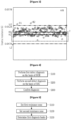
- FIG. 2 is a drawing illustrating an example for explaining a first resistance zone according to the exemplary embodiment.
- control unit 23 may determine first reference resistance and a resistance deviation on the basis of a plurality of first internal resistance values related to the plurality of battery banks, and determine a first resistance zone on the basis of the first reference resistance and the resistance deviation.
- control unit 23 may calculate the internal resistance value of each of the plurality of battery banks on the basis of the following Equation 1.
- DCIR i ⁇ V i I
- DCIR is the internal resistance ( ⁇ ) of a battery bank
- I is the bank current (mA).
- ⁇ V is a change in the voltage (mV) of the battery bank for a predetermined time.
- i is an index identifying each battery bank, and may be equal to or larger than 1 and equal to or smaller than n.
- n may be the total number of the plurality of battery banks to undergo state diagnosis by a battery diagnosis apparatus 100.
- the first voltage V1 may be the bank voltage measured at the first time when charging started
- the second voltage V2 may be bank voltage measured at the second time that was a predetermined time later from the first time.
- the control unit 23 may set the median value or average of the plurality of internal resistance values of the plurality of battery banks, as a first reference resistance R1. It may be preferable that a first reference resistance R1 be the median value of the internal resistance values of a plurality of target banks. Specifically, the control unit 23 may set an internal resistance value which is positioned at the center when the internal resistance values of the plurality of battery banks are arranged in the order of magnitude, as a first reference resistance R1.
- control unit 23 may calculate the median absolute deviation MAD of the plurality of internal resistance values of the plurality of battery banks related to the first reference resistance R1, and convert the median absolute deviation MAD into a resistance deviation, using a predetermined scale constant.
- control unit 23 may calculate the median absolute deviation MAD of the plurality of internal resistance values of the plurality of battery banks related to the first reference resistance R1, using the following Equation 2.
- D median DCIR i ⁇ R1 , 1 ⁇ i ⁇ n
- i is an index indicating each battery bank, and may be equal to or larger than 1 and equal to or smaller than n.
- n may be the total number of the plurality of battery banks to be diagnosed.
- R1 is a first reference resistance
- DCIR i is the internal resistance of the i-th battery bank.
- Median() is a function that outputs the median value related to
- D may be the median absolute deviation (hereinafter, referred to as the absolute deviation).
- D may be an absolute deviation between the first reference resistance R1 and the internal resistance (DCIR i ) values of the plurality of battery banks.
- control unit 23 may calculate a scale constant, using the following Equation 3, and convert the absolute deviation into a resistance deviation, using the following Equation 4.
- C ⁇ 1 2 ⁇ erfcinv a
- C is a scale constant
- erfcinv(a) is an inverse complementary error function
- a is a constant.
- erfcinv(3/2) may be the output value of the inverse complementary error function related to the input value 3/2.
- S is a resistance deviation that is obtained by conversion
- D is an absolute deviation according to Equation 2
- C is a scale constant according to Equation 3.
- control unit 23 may determine a first resistance zone on the basis of the first reference resistance R1 and the resistance deviation S.
- the control unit 23 may calculate a first upper threshold U1 by adding the resistance deviation S to the first reference resistance R1. In other words, the control unit 23 may calculate the first upper threshold U1 by calculating "R1 + S". Also, the control unit 23 may calculate a first lower threshold L1 by subtracting the resistance deviation from the first reference resistance R1. In other words, the control unit 23 may calculate the first lower threshold L1 by calculating "R1 - S”.
- the Y-axis represents internal resistance ( ⁇ )
- the X-axis may represent the serial numbers of battery banks.
- the values on the X-axis are values independent from internal resistance values, and any factor capable of identifying each of the plurality of battery banks may be applied without limitation.
- a first lower threshold L1 and a first upper threshold U1 may be set symmetrically relative to the first reference resistance R1.
- the resistance zone from the first lower threshold L1 to the first upper threshold U1 may be set as the first resistance zone.
- all of the internal resistance values of the plurality of battery banks may be included in the first resistance zone.
- FIG. 3 is a drawing illustrating an example for explaining a second resistance zone according to the exemplary embodiment.
- the control unit 23 may determine, as target banks, a plurality of battery banks having internal resistance values smaller than the first reference resistance R1 among the plurality of battery banks.
- the control unit 23 may determine a second reference resistance R2 on the basis of a plurality of second internal resistance values related to the plurality of target banks.
- the control unit 23 may determine a second resistance zone on the basis of the second reference resistance R2 and a parallel deviation.
- a parallel deviation P may be a value corresponding to the connection structure of a plurality of battery cells included in a target bank.
- control unit 23 may determine, as target banks, a plurality of battery banks having internal resistance values smaller than the first reference resistance R1 among the plurality of battery banks.
- the median value or average of the plurality of battery banks may be applied.
- the first reference resistance R1 is the average of the internal resistance values of the plurality of battery banks
- battery banks having internal resistance values equal to or smaller than the average may be selected as target banks.
- the first reference resistance R1 is the median value of the internal resistance values of the plurality of battery banks
- battery banks having internal resistance values included in the bottom 50% may be selected as target banks.
- control unit 23 may determine a second reference resistance R2 on the basis of a plurality of second internal resistance values related to the plurality of target banks.
- the second reference resistance R2 is a value representing the internal resistance values of the plurality of target banks, and may be the median value, the average, or the like. It may be preferable that the second reference resistance R2 be the average of the plurality of internal resistance values of the plurality of target banks.
- control unit 23 may calculate a parallel coefficient ⁇ from the number of parallel connections, and calculate a parallel deviation P by multiplying the parallel coefficient ⁇ and the second reference resistance R2 together.
- control unit 23 may calculate a parallel coefficient using the following Equation 5.
- ⁇ is a parallel coefficient
- m is the number of parallel connections
- b is a constant, and may be, for example, 0 or 1.
- control unit 23 may calculate a parallel deviation P using the following Equation 6.
- P is a parallel deviation
- R2 is a second reference resistance
- ⁇ is a parallel coefficient according to Equation 5.
- P R2 ⁇ ⁇
- control unit 23 may determine a second resistance zone on the basis of the second reference resistance R2 and the parallel deviation P.
- control unit 23 may calculate a second upper threshold U2 by adding the parallel deviation P to the second reference resistance R2. In other words, the control unit 23 may calculate a second upper threshold U2 by calculating "R2 + P". The control unit 23 may calculate a second lower threshold L2 by subtracting the parallel deviation P from the second reference resistance R2. In other words, the control unit 23 may calculate a second lower threshold L2 by calculating "R2 - P".
- the Y-axis represents internal resistance ( ⁇ )
- the X-axis may represent the serial numbers of battery banks.
- the values on the X-axis are values independent from internal resistance, and any factor capable of identifying each of the plurality of battery banks may be applied without limitation.
- the plurality of battery banks may be identical.
- a second lower threshold L2 and a second upper threshold U2 may be set symmetrically relative to the second reference resistance R2.
- the resistance zone from the second lower threshold L2 to the second upper threshold U2 may be set as a second resistance zone.
- the control unit 23 may determine first diagnosis banks in the light of both of the first resistance zone and the second resistance zone, not in the light of only one of the first resistance zone and the second resistance zone.
- control unit 23 may determine that battery banks having internal resistance values belonging to both of the first resistance zone and the second resistance zone among the plurality of battery banks are normal.
- the control unit 23 may determine that battery banks having internal resistance which is out of the first resistance zone or the second resistance zone among the plurality of battery banks are abnormal, and determine them as first diagnosis banks.
- the battery banks determined as normal during the first defect diagnosis may be used as reference battery banks for the second defect diagnosis.
- the internal resistance values of a first battery bank B1 and a second battery bank B2 of the plurality of battery banks may be included in the first resistance zone.
- the internal resistance values of the first battery bank B1 and the second battery bank B2 may not be included in the second resistance zone.
- the control unit 23 may determine the first battery bank B1 and the second battery bank B2 as first diagnosis banks, and then further diagnose whether there is any defect, on the basis of the state of charge (SOC).
- SOC state of charge
- FIG. 4 is a flow chart for explaining a battery diagnosis method according to an exemplary embodiment
- FIG. 5 is a flow chart for explaining the first defect diagnosis step S100 of FIG. 4 in detail
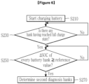
- FIG. 6 is a flow chart for explaining the second defect diagnosis step S200 of FIG. 4 in detail.
- control unit 23 performs a first defect diagnosis on the plurality of battery banks on the basis of the internal resistance (DCIR) (S100).
- DCIR internal resistance
- step S100 referring to FIG. 5 , the control unit 23 determines a first reference resistance and a resistance deviation on the basis of a plurality of first internal resistance values related to the plurality of battery banks, and determines a first resistance zone on the basis of the first reference resistance and the resistance deviation (S110).
- control unit 23 may set the median value of the plurality of internal resistance values of the plurality of battery banks, as a first reference resistance R1.
- the control unit 23 may calculate the median absolute deviation MAD between the first reference resistance R1 and the internal resistance values of the plurality of battery banks, using the above Equation 2.
- the control unit 23 may determine a scale constant using the above Equation 3, and convert the median absolute deviation MAD into a resistance deviation S using the above Equation 4.
- the control unit 23 may calculate a first upper threshold U1 by adding the resistance deviation S to the first reference resistance R1.
- the control unit 23 may calculate a first lower threshold L1 by subtracting the resistance deviation S from the first reference resistance R1. Referring to FIG. 2 , the control unit 23 may determine the resistance zone from the first lower threshold L1 to the first upper threshold U1, as a first resistance zone.
- step S100 the control unit 23 determines, as target banks, a plurality of battery banks having internal resistance values smaller than the first reference resistance R1 among the plurality of battery banks, and determines a second reference resistance R2 on the basis of a plurality of second internal resistance values related to the plurality of target banks, and determines a second resistance zone on the basis of the second reference resistance R2 and a parallel deviation (S130).
- the control unit 23 may select, as target banks, battery banks having internal resistance values included in the bottom 50%.
- the control unit 23 may determine the average of the internal resistance values of the plurality of target banks, as a second reference resistance R2. Also, the control unit 23 may calculate a parallel coefficient ⁇ from the number of parallel connections (m), and calculate a parallel deviation P by multiplying the parallel coefficient ⁇ and the second reference resistance R2 together. For example, the control unit 23 may calculate a parallel coefficient ⁇ using the above Equation 5, and calculate a parallel deviation P using the above Equation 6. In this case, the parallel deviation P may be a value corresponding to the connection structure of a plurality of battery cells included in a target bank.
- the control unit 23 may calculate a second upper threshold U2 by adding the parallel deviation P to the second reference resistance R2.
- the control unit 23 may calculate a second lower threshold L2 by subtracting the parallel deviation P from the second reference resistance R2. Referring to FIG. 3 , the control unit 23 may determine the resistance zone from the second lower threshold L2 to the second upper threshold U2, as a second resistance zone.
- step S100 the control unit 23 determines, as first diagnosis banks, battery banks having internal resistance values which are out of the first resistance zone or the second resistance zone among the plurality of battery banks (S150).
- the internal resistance values of a first battery bank B1 and a second battery bank B2 of the plurality of battery banks may be included in the first resistance zone.
- the internal resistance of the first battery bank B1 and the second battery bank B2 may not be included in the second resistance zone.
- the control unit 23 may determine the first battery bank B1 and the second battery bank B2 as first diagnosis banks.
- control unit 23 performs a second defect diagnosis on the battery banks on the basis of the states of charge (SOC) of the plurality of battery banks (S200).
- control unit 23 may perform a second defect diagnosis on the first diagnosis banks. According to another exemplary embodiment, the control unit 23 may perform a second defect diagnosis on the plurality of battery banks.
- step S200 when a predetermined condition is satisfied, the control unit 23 proceeds to a charging mode of charging the battery 10 with the electricity of an external device (S210).
- the control unit 23 may perform the charging mode.
- SOC state-of-charge
- step S200 the control unit 23 determines whether a first diagnosis condition that there should be at least one battery bank having reached a state of charge (SOC) indicating a full charge state among the plurality of battery banks included in the battery 10 is satisfied (S230).
- SOC state of charge
- the control unit 23 may perform a second defect diagnosis in which it determines the ratios of second state-of-charge change amounts ( ⁇ SOC2) of battery banks to a first state-of-charge change amount ( ⁇ SOC1) of a reference battery bank ( ⁇ SOC2/ ⁇ SOC1), and determines second diagnosis banks by comparing the determined ratios with a diagnosis reference value.
- ⁇ SOC2 second state-of-charge change amounts
- ⁇ SOC1 first state-of-charge change amount of a reference battery bank
- the control unit 23 may determine that some battery banks having reached a full charge state exist. In other words, the full charge state may be determined by the predetermined battery use range.
- step S200 when it is determined that the first diagnosis condition is satisfied (Yes in step S230), the control unit 23 determines whether a second diagnosis condition that the state-of-charge change amounts of the plurality of battery banks should be equal to or larger than a condition reference value is satisfied (S250).
- condition reference value is 45%.
- the control unit 23 may determine that the second diagnosis condition is satisfied.
- step S200 when it is determined that the second diagnosis condition is satisfied (Yes in S250), the control unit 23 determines the ratios of the second state-of-charge change amounts of battery banks to the first state-of-charge change amount of the reference battery bank, and determines second diagnosis banks by comparing the ratios with the diagnosis reference value (S270).
- the reference battery bank As the reference battery bank, a battery bank diagnosed as normal or a new battery bank which has never been used may be determined.
- the reference battery bank may be a battery bank determined as normal in the first defect diagnosis step.
- the control unit 23 may determine, as a reference battery bank, a battery bank having the smallest state-of-charge change amount ( ⁇ SOC) calculated in the second defect diagnosis step.
- ⁇ SOC state-of-charge change amount
- the present invention is not limited thereto, and the control unit 23 may determine, as a reference battery bank, one of the plurality of battery banks determined as being normal during the first defect diagnosis.
- the battery 10 includes first to fifth battery banks B1 to B5, and in the first defect diagnosis step, the first and second battery banks B1 and B2 are diagnosed as first diagnosis banks corresponding to the abnormal state, and the third to fifth battery banks B3, B4, and B5 are diagnosed as normal.
- the control unit 23 may determine the fourth battery bank B4 having the smallest state-of-charge change amount, as a reference battery bank.
- the diagnosis reference value may be determined on the basis of the number of battery cells connected in parallel in a battery bank.
- Th1 is a diagnosis reference value
- m is the number of battery cells connected in parallel in a battery bank
- n is a natural number smaller than m.
- n when it is desired to diagnose a case where at least one battery cell is defective, n may be set to 1. For another example, when it is desired to diagnose a case where two or more battery cells are defective as a case where there are some defective battery cells, n may be set to 2. In other words, when it is desired to detect battery banks each of which includes at least one defect battery cell, n in the above Equation 1 may be set to 1.
- m 5 and n is 1.
- the diagnosis reference value Th1 may be set to 1.25.
- the control unit 23 may determine the first battery bank B1 as a second diagnosis bank.
- control unit 23 diagnoses, as defective battery banks, battery banks determined as first diagnosis banks and second diagnosis banks among the plurality of battery banks (S300).
- the accuracy of diagnosis can be improved by finally diagnosing defective battery banks by a first defect diagnosis method of diagnosing defects on the basis of the internal resistance of battery banks and a second defect diagnosis method of diagnosing defects on the basis of the states of charge (SOC) of battery banks.
- SOC states of charge
- the control unit 23 may diagnose defective battery banks by only the second defect diagnosis method of diagnosing defects on the basis of the states of charge (SOC) of battery banks.
- the control unit 23 may determine a reference battery bank by the first defect diagnosis method described above, and determine second diagnosis banks on the basis of the state-of-charge change amount ratios between the reference battery bank and battery banks.
- the second diagnosis banks may be defective battery banks.
Landscapes
- General Physics & Mathematics (AREA)
- Physics & Mathematics (AREA)
- Engineering & Computer Science (AREA)
- Chemical & Material Sciences (AREA)
- Manufacturing & Machinery (AREA)
- Chemical Kinetics & Catalysis (AREA)
- Electrochemistry (AREA)
- General Chemical & Material Sciences (AREA)
- Power Engineering (AREA)
- Microelectronics & Electronic Packaging (AREA)
- Secondary Cells (AREA)
- Charge And Discharge Circuits For Batteries Or The Like (AREA)
- Tests Of Electric Status Of Batteries (AREA)
Abstract
Description
- This application claims priority to and the benefit of
Korean Patent Application No. 1 0-2022-0055702 filed in the Korean Intellectual Property Office on May 4, 2022 - The present invention relates to a battery diagnosis method of diagnosing the states of battery banks on the basis of the internal resistance and the states of charge (SOC), and a battery system for providing the method.
- Recently, as the demand for portable electronic goods such as laptops, video cameras, and portable phones has rapidly increased, and the development of electric vehicles, energy storage batteries, robots, satellites, and so on has accelerated, research on high-performance batteries capable of repetitive charging and discharging has been actively conducted.
- The currently commercialized batteries include nickel cadmium batteries, nickel hydrogen batteries, nickel zinc batteries, lithium batteries, etc., and among them, lithium batteries have freedom to be charged and discharged since they have less memory effect as compared to nickel-based batteries, and have very low self-discharge rates and high energy densities. For these advantages, they are getting the spotlight.
- In general, batteries each of which includes a plurality of battery cells connected are used depending on the purpose of use. For example, a battery bank including a plurality of battery cells connected in parallel in order to increase the capacity may be used, or a battery bank including a plurality of battery cells connected in series in order to increase the output voltage may be used.
- Battery banks have difficulties in terms of cost and structure in monitoring each of the battery cells connected in parallel. In general, batteries including at least one battery bank have a structural feature that they cannot be easily decomposed and separated in order to improve the stability against impact. Therefore, there are difficulties in diagnosing whether each of the battery cells included in battery banks is defective.
- Further, in the case where a battery includes a plurality of battery banks, and some battery cells included in some battery banks are defective, the battery may be damaged by an inrush current which is caused by a difference in capacity between a plurality of battery banks.
- The present invention has been made in an effort to provide a battery diagnosis method capable of accurately diagnosing the state of a battery including a plurality of battery cells, and a battery system for providing the method.
- An exemplary embodiment of the present invention provides a battery system including a battery that includes a plurality of battery banks each of which includes a plurality of battery cells, and a control unit that determines the ratios of second state-of-charge change amounts of battery banks to a first state-of-charge change amount of a reference battery bank, and diagnoses defects of battery banks by comparing the ratios with a diagnosis reference value, when a predetermined diagnosis condition is satisfied in a charging mode of charging the battery with the electricity of an external device, wherein the diagnosis reference value is determined on the basis of the number of battery cells connected in parallel in a battery bank.
- Another exemplary embodiment of the present invention provides a battery system including a battery that includes a plurality of battery banks each of which includes a plurality of battery cells, and a control unit that determines first diagnosis banks on the basis of the internal resistance of the plurality of battery banks, and determines second diagnosis banks by comparing the ratios of second state-of-charge change amounts of battery banks to a first state-of-charge change amount of a reference battery bank with a diagnosis reference value, when a predetermined diagnosis condition is satisfied in a charging mode of charging the battery with the electricity of an external device, and diagnoses, as defective battery banks, battery banks determined as the first diagnosis banks and the second diagnosis banks among the plurality of battery banks, wherein the diagnosis reference value is determined on the basis of the number of battery cells connected in parallel in a battery bank.
- Yet another exemplary embodiment of the present invention provides a battery diagnosis method which is a method of diagnosing defects of a battery including a plurality of battery banks each of which includes a plurality of battery cells, and includes a first defect diagnosis step of determining first diagnosis banks on the basis of the internal resistance of the plurality of battery banks, a second defect diagnosis step of determining second diagnosis banks by comparing the ratios of second state-of-charge change amounts of battery banks to a first state-of-charge change amount of a reference battery bank with a diagnosis reference value, when a predetermined diagnosis condition is satisfied in a charging mode of charging the battery with the electricity of an external device, and a diagnosis confirming step of diagnosing, as defective battery banks, battery banks determined as the first diagnosis banks and the second diagnosis banks among the plurality of battery banks, wherein the diagnosis reference value is determined on the basis of the number of battery cells connected in parallel in a battery bank.
- The present invention can determine a reference value for determining defects of battery banks, on the basis of a value corresponding to the number of battery cells connected in parallel, not on the basis of a fixed value, thereby diagnosing defects of battery banks including battery cells connected in parallel, with high accuracy.
- The present invention can finally estimate defective battery banks through a first defect diagnosis method of diagnosing defects on the basis of the internal resistance of battery banks and a second defect diagnosis method of diagnosing defects on the basis of the states of charge (SOC) of battery banks, whereby the accuracy of diagnosis can improve.
- The present invention can improve the accuracy of diagnosis and predict the battery replacement cycle with high accuracy, thereby saving the battery replacement cost.
-
-
FIG. 1 is a drawing for explaining a battery system according to an exemplary embodiment. -
FIG. 2 is a drawing illustrating an example for explaining a first resistance zone according to the exemplary embodiment. -
FIG. 3 is a drawing illustrating an example for explaining a second resistance zone according to the exemplary embodiment. -
FIG. 4 is a flow chart for explaining a battery diagnosis method according to an exemplary embodiment. -
FIG. 5 is a flow chart for explaining the first defect diagnosis step S100 ofFIG. 4 in detail. -
FIG. 6 is a flow chart for explaining the second defect diagnosis step S200 ofFIG. 4 in detail. - Hereinafter, exemplary embodiments disclosed in this specification will be described in detail with reference to the accompanying drawings; however, the same or similar constituent components are denoted by the same or similar reference symbols, and a repeated description thereof will not be made. As used herein, the suffix 'module' and/or the suffix 'unit' for constituent elements are given and used interchangeably in consideration of only ease of preparing this specification, and the suffixes themselves do not have meanings or roles distinguishable from each other. Further, when describing exemplary embodiments disclosed in this specification, detailed descriptions of publicly known technologies will be omitted if it is determined that specific description thereof may obscure the gist of the exemplary embodiments disclosed in this specification. Furthermore, the accompanying drawings are provided for helping to easily understand exemplary embodiments disclosed in the present specification, and the technical spirit disclosed in the present specification is not limited by the accompanying drawings, and it will be appreciated that the present invention includes all of the modifications, equivalent matters, and substitutes included in the spirit and the technical scope of the present invention.
- Terms including an ordinal number, such as first and second, are used for describing various constituent elements, but the constituent elements are not limited by the terms. The terms are used only to discriminate one constituent element from another constituent element.
- When a constituent element is referred to as being "connected" or "coupled" to another constituent element, it will be appreciated that it may be directly connected or coupled to the other constituent element or intervening other constituent elements may be present. In contrast, when a constituent element is referred to as being "directly connected" or "directly coupled" to another constituent element, it will be appreciated that there are no intervening other constituent elements present.
- In the present application, it will be appreciated that terms "including" and "having" are intended to designate the existence of characteristics, numbers, steps, operations, constituent elements, and components described in the specification or a combination thereof, and do not exclude a possibility of the existence or addition of one or more other characteristics, numbers, steps, operations, constituent elements, and components, or a combination thereof in advance.
-
FIG. 1 is a drawing for explaining a battery system according to an exemplary embodiment. - Referring to
FIG. 1 , a battery system 1 includes abattery 10 and aBMS 20. - The
battery 10 may include a plurality of battery banks connected in series and/or in parallel. Each battery bank may include a plurality of battery cells connected in parallel. Each battery cell refers to one independent cell which has a cathode terminal and an anode terminal and can be physically separated. For example, one pouch type lithium polymer cell may be regarded as a battery cell. -
FIG. 1 shows that thebattery 10 includes three battery banks B1, B2, and B3 connected in series and each of the three battery banks B1, B2, and B3 includes three battery cells connected in parallel. However, the present invention is not limited thereto, and thebattery 10 may include a plurality of battery banks which is connected in parallel and each of which includes a plurality of battery cells. Hereinafter, each of the plurality of battery banks included in thebattery 10 may include a plurality of battery cells having the same connection structure (series connections and parallel connections). In other words, parallel coefficients (µ) to be described may be the same. - The
BMS 20 includes ameasuring unit 21, a storage unit 22, and acontrol unit 23.FIG. 1 shows that theBMS 20 is included in the battery system 1; however, the present invention is not limited thereto, and the BMS may be mounted outside the battery system 1. Also, for example, theBMS 20 may be mounted in various systems requiring defect diagnosis on battery banks, and may function as a defect diagnosis device for thebattery 10. - The
measuring unit 21 may include a voltage sensor (not shown in the drawings) for measuring a bank voltage which is the voltage between both terminals of each of the plurality of battery banks, and a current sensor (not shown in the drawings) for measuring a bank current which is the current flowing through each of the plurality of battery banks. Themeasuring unit 21 may transmit the measurement results to thecontrol unit 23. - With respect to each of the plurality of battery banks, the
measuring unit 21 may measure a bank voltage V1 at a first time when charging of thebattery 10 starts, and measure a bank voltage V2 at a second time that is a predetermined time later from the first time. Thecontrol unit 23 may calculate the voltage difference between the voltages of the battery bank measured at the first time and the second time, respectively ( ΔV = | V1 - V2| ). - With respect to each of the plurality of battery banks, the
measuring unit 21 may measure the bank voltage and the bank current in a charging mode or a discharging mode. In this case, the bank current may be a charging current or a discharging current. For example, in the charging mode, with respect to each of the plurality of battery banks, thecontrol unit 23 may determine the internal resistance on the basis of the voltage difference ( ΔV = | V2 - V1 | ) and the charging current. Hereinafter, it is assumed that the battery banks is capable of charging and/or discharging at constant current. - With respect to each of the plurality of battery banks, the storage unit 22 may store an internal resistance value which the
control unit 23 estimates on the basis of at least one of the bank voltage and the bank current. With respect to each of the plurality of battery banks, the storage unit may store the state of charge (SOC) which thecontrol unit 23 estimates on the basis of at least one of the bank voltage and the bank current. By various known prior methods, thecontrol unit 23 may estimate the internal resistance value and the state of charge (SOC) relative to each of the plurality of battery banks. - The
control unit 23 may perform a first defect diagnosis of determining first diagnosis banks on the basis of the internal resistance values of the plurality of battery banks. Thecontrol unit 23 may perform a second defect diagnosis of determining second diagnosis banks on the basis of the states of charge (SOC) of the plurality of battery banks. In this case, the first diagnosis banks are battery banks determined as abnormal as the result of the first defect diagnosis. The second diagnosis banks are battery banks determined as abnormal as the result of the second defect diagnosis. According to the exemplary embodiment, a battery bank determined as normal during the first defect diagnosis may be used as a reference battery bank during the second defect diagnosis. - For example, the
control unit 23 may perform the second defect diagnosis on all of the plurality of battery banks, regardless of the result of the first defect diagnosis. For another example, thecontrol unit 23 may perform the second defect diagnosis on only battery banks determined as first diagnosis banks among the plurality of battery banks during the first defect diagnosis. In this case, the number of diagnosis objects of the second defect diagnosis decreases, so the diagnosis time can be saved. - According to the exemplary embodiment, the
control unit 23 may diagnose, as defective battery banks, battery banks determined as first diagnosis banks and second diagnosis banks among plurality of battery banks. According to another exemplary embodiment, thecontrol unit 23 may diagnose battery banks of the plurality of battery banks determined as second diagnosis banks, as defective battery banks. - Hereinafter, a method of determining a first resistance zone and a second resistance zone for the first defect diagnosis will be described in detail with reference to
FIG. 2 andFIG. 3 . -
FIG. 2 is a drawing illustrating an example for explaining a first resistance zone according to the exemplary embodiment. - Referring to
FIG. 2 , thecontrol unit 23 may determine first reference resistance and a resistance deviation on the basis of a plurality of first internal resistance values related to the plurality of battery banks, and determine a first resistance zone on the basis of the first reference resistance and the resistance deviation. - First, the
control unit 23 may calculate the internal resistance value of each of the plurality of battery banks on the basis of the following Equation 1.
- Here, DCIR is the internal resistance (Ω) of a battery bank, and I is the bank current (mA). ΔV is a change in the voltage (mV) of the battery bank for a predetermined time. i is an index identifying each battery bank, and may be equal to or larger than 1 and equal to or smaller than n. n may be the total number of the plurality of battery banks to undergo state diagnosis by a
battery diagnosis apparatus 100. - For example, the
control unit 23 may calculate the difference between a first voltage V1 and a second voltage V2 of a battery bank, i.e., the voltage difference (ΔV = | V2 - V1 | ). Since the magnitude of the charging current (I) for the battery bank is constant, thecontrol unit 23 may calculate the internal resistance (DCIR) of the battery bank on the basis of the voltage difference (ΔV) and the bank current (I). In this case, the first voltage V1 may be the bank voltage measured at the first time when charging started, and the second voltage V2 may be bank voltage measured at the second time that was a predetermined time later from the first time. - Subsequently, the
control unit 23 may set the median value or average of the plurality of internal resistance values of the plurality of battery banks, as a first reference resistance R1. It may be preferable that a first reference resistance R1 be the median value of the internal resistance values of a plurality of target banks. Specifically, thecontrol unit 23 may set an internal resistance value which is positioned at the center when the internal resistance values of the plurality of battery banks are arranged in the order of magnitude, as a first reference resistance R1. - Next, the
control unit 23 may calculate the median absolute deviation MAD of the plurality of internal resistance values of the plurality of battery banks related to the first reference resistance R1, and convert the median absolute deviation MAD into a resistance deviation, using a predetermined scale constant. - For example, the
control unit 23 may calculate the median absolute deviation MAD of the plurality of internal resistance values of the plurality of battery banks related to the first reference resistance R1, using the followingEquation 2.
- Here, i is an index indicating each battery bank, and may be equal to or larger than 1 and equal to or smaller than n. n may be the total number of the plurality of battery banks to be diagnosed. R1 is a first reference resistance, and DCIRi is the internal resistance of the i-th battery bank. Median() is a function that outputs the median value related to |DCIRi - R1|, and D may be the median absolute deviation (hereinafter, referred to as the absolute deviation). In other words, D may be an absolute deviation between the first reference resistance R1 and the internal resistance (DCIRi) values of the plurality of battery banks.
- For example, the
control unit 23 may calculate a scale constant, using the following Equation 3, and convert the absolute deviation into a resistance deviation, using the following Equation 4.
- Here, C is a scale constant, and erfcinv(a) is an inverse complementary error function, and a is a constant. For example, when a is 3/2, erfcinv(3/2) may be the output value of the inverse complementary error function related to the input value 3/2.

- Here, S is a resistance deviation that is obtained by conversion, and D is an absolute deviation according to
Equation 2, and C is a scale constant according to Equation 3. - Next, the
control unit 23 may determine a first resistance zone on the basis of the first reference resistance R1 and the resistance deviation S. - Specifically, referring to
FIG. 2 , thecontrol unit 23 may calculate a first upper threshold U1 by adding the resistance deviation S to the first reference resistance R1. In other words, thecontrol unit 23 may calculate the first upper threshold U1 by calculating "R1 + S". Also, thecontrol unit 23 may calculate a first lower threshold L1 by subtracting the resistance deviation from the first reference resistance R1. In other words, thecontrol unit 23 may calculate the first lower threshold L1 by calculating "R1 - S". - Referring to
FIG. 2 , the Y-axis represents internal resistance (Ω), and the X-axis may represent the serial numbers of battery banks. In other words, the values on the X-axis are values independent from internal resistance values, and any factor capable of identifying each of the plurality of battery banks may be applied without limitation. - For example, a first lower threshold L1 and a first upper threshold U1 may be set symmetrically relative to the first reference resistance R1. The resistance zone from the first lower threshold L1 to the first upper threshold U1 may be set as the first resistance zone. Further, in the exemplary embodiment of
FIG. 2 , all of the internal resistance values of the plurality of battery banks may be included in the first resistance zone. -
FIG. 3 is a drawing illustrating an example for explaining a second resistance zone according to the exemplary embodiment. - Referring to
FIG. 3 , thecontrol unit 23 may determine, as target banks, a plurality of battery banks having internal resistance values smaller than the first reference resistance R1 among the plurality of battery banks. Thecontrol unit 23 may determine a second reference resistance R2 on the basis of a plurality of second internal resistance values related to the plurality of target banks. Thecontrol unit 23 may determine a second resistance zone on the basis of the second reference resistance R2 and a parallel deviation. In this case, a parallel deviation P may be a value corresponding to the connection structure of a plurality of battery cells included in a target bank. - First, the
control unit 23 may determine, as target banks, a plurality of battery banks having internal resistance values smaller than the first reference resistance R1 among the plurality of battery banks. - As the first reference resistance R1, the median value or average of the plurality of battery banks may be applied. In the case where the first reference resistance R1 is the average of the internal resistance values of the plurality of battery banks, battery banks having internal resistance values equal to or smaller than the average may be selected as target banks. On the contrary, in the case where the first reference resistance R1 is the median value of the internal resistance values of the plurality of battery banks, battery banks having internal resistance values included in the bottom 50% may be selected as target banks.
- Subsequently, the
control unit 23 may determine a second reference resistance R2 on the basis of a plurality of second internal resistance values related to the plurality of target banks. - The second reference resistance R2 is a value representing the internal resistance values of the plurality of target banks, and may be the median value, the average, or the like. It may be preferable that the second reference resistance R2 be the average of the plurality of internal resistance values of the plurality of target banks.
- Next, the
control unit 23 may calculate a parallel coefficient µ from the number of parallel connections, and calculate a parallel deviation P by multiplying the parallel coefficient µ and the second reference resistance R2 together. - For example, the
control unit 23 may calculate a parallel coefficient using the following Equation 5. Here, µ is a parallel coefficient, and m is the number of parallel connections, b is a constant, and may be, for example, 0 or 1. In other words, the parallel coefficient µ may be related to the reciprocal of the number of parallel connections (m).
- For example, the
control unit 23 may calculate a parallel deviation P using the following Equation 6. Here, P is a parallel deviation, and R2 is a second reference resistance, and µ is a parallel coefficient according to Equation 5.
- Next, the
control unit 23 may determine a second resistance zone on the basis of the second reference resistance R2 and the parallel deviation P. - Specifically, the
control unit 23 may calculate a second upper threshold U2 by adding the parallel deviation P to the second reference resistance R2. In other words, thecontrol unit 23 may calculate a second upper threshold U2 by calculating "R2 + P". Thecontrol unit 23 may calculate a second lower threshold L2 by subtracting the parallel deviation P from the second reference resistance R2. In other words, thecontrol unit 23 may calculate a second lower threshold L2 by calculating "R2 - P". - Referring to
FIG. 3 , the Y-axis represents internal resistance (Ω), and the X-axis may represent the serial numbers of battery banks. In other words, the values on the X-axis are values independent from internal resistance, and any factor capable of identifying each of the plurality of battery banks may be applied without limitation. Specifically, in the exemplary embodiments ofFIG. 2 andFIG. 3 , the plurality of battery banks may be identical. - For example, a second lower threshold L2 and a second upper threshold U2 may be set symmetrically relative to the second reference resistance R2. The resistance zone from the second lower threshold L2 to the second upper threshold U2 may be set as a second resistance zone.
- The
control unit 23 may determine first diagnosis banks in the light of both of the first resistance zone and the second resistance zone, not in the light of only one of the first resistance zone and the second resistance zone. - Preferably, the
control unit 23 may determine that battery banks having internal resistance values belonging to both of the first resistance zone and the second resistance zone among the plurality of battery banks are normal. Thecontrol unit 23 may determine that battery banks having internal resistance which is out of the first resistance zone or the second resistance zone among the plurality of battery banks are abnormal, and determine them as first diagnosis banks. According to an exemplary embodiment, the battery banks determined as normal during the first defect diagnosis may be used as reference battery banks for the second defect diagnosis. - For example, referring to
FIG. 2 , the internal resistance values of a first battery bank B1 and a second battery bank B2 of the plurality of battery banks may be included in the first resistance zone. However, referring toFIG. 3 , the internal resistance values of the first battery bank B1 and the second battery bank B2 may not be included in the second resistance zone. In this case, thecontrol unit 23 may determine the first battery bank B1 and the second battery bank B2 as first diagnosis banks, and then further diagnose whether there is any defect, on the basis of the state of charge (SOC). -
FIG. 4 is a flow chart for explaining a battery diagnosis method according to an exemplary embodiment, andFIG. 5 is a flow chart for explaining the first defect diagnosis step S100 ofFIG. 4 in detail, andFIG. 6 is a flow chart for explaining the second defect diagnosis step S200 ofFIG. 4 in detail. - Hereinafter, on the basis of
FIG. 1 to FIG. 6 , a method of diagnosing defects of a plurality of battery banks and a battery system for providing the method will be described. - Referring to
FIG. 4 , first, thecontrol unit 23 performs a first defect diagnosis on the plurality of battery banks on the basis of the internal resistance (DCIR) (S100). - In step S100, referring to
FIG. 5 , thecontrol unit 23 determines a first reference resistance and a resistance deviation on the basis of a plurality of first internal resistance values related to the plurality of battery banks, and determines a first resistance zone on the basis of the first reference resistance and the resistance deviation (S110). - For example, the
control unit 23 may set the median value of the plurality of internal resistance values of the plurality of battery banks, as a first reference resistance R1. Thecontrol unit 23 may calculate the median absolute deviation MAD between the first reference resistance R1 and the internal resistance values of the plurality of battery banks, using theabove Equation 2. Thecontrol unit 23 may determine a scale constant using the above Equation 3, and convert the median absolute deviation MAD into a resistance deviation S using the above Equation 4. - The
control unit 23 may calculate a first upper threshold U1 by adding the resistance deviation S to the first reference resistance R1. Thecontrol unit 23 may calculate a first lower threshold L1 by subtracting the resistance deviation S from the first reference resistance R1. Referring toFIG. 2 , thecontrol unit 23 may determine the resistance zone from the first lower threshold L1 to the first upper threshold U1, as a first resistance zone. - In step S100, the
control unit 23 determines, as target banks, a plurality of battery banks having internal resistance values smaller than the first reference resistance R1 among the plurality of battery banks, and determines a second reference resistance R2 on the basis of a plurality of second internal resistance values related to the plurality of target banks, and determines a second resistance zone on the basis of the second reference resistance R2 and a parallel deviation (S130). - For example, in the case where the first reference resistance R1 is the median value of the internal resistance values of the plurality of battery banks, the
control unit 23 may select, as target banks, battery banks having internal resistance values included in the bottom 50%. - The
control unit 23 may determine the average of the internal resistance values of the plurality of target banks, as a second reference resistance R2. Also, thecontrol unit 23 may calculate a parallel coefficient µ from the number of parallel connections (m), and calculate a parallel deviation P by multiplying the parallel coefficient µ and the second reference resistance R2 together. For example, thecontrol unit 23 may calculate a parallel coefficient µ using the above Equation 5, and calculate a parallel deviation P using the above Equation 6. In this case, the parallel deviation P may be a value corresponding to the connection structure of a plurality of battery cells included in a target bank. - The
control unit 23 may calculate a second upper threshold U2 by adding the parallel deviation P to the second reference resistance R2. Thecontrol unit 23 may calculate a second lower threshold L2 by subtracting the parallel deviation P from the second reference resistance R2. Referring toFIG. 3 , thecontrol unit 23 may determine the resistance zone from the second lower threshold L2 to the second upper threshold U2, as a second resistance zone. - In step S100, the
control unit 23 determines, as first diagnosis banks, battery banks having internal resistance values which are out of the first resistance zone or the second resistance zone among the plurality of battery banks (S150). - For example, referring to
FIG. 2 , the internal resistance values of a first battery bank B1 and a second battery bank B2 of the plurality of battery banks may be included in the first resistance zone. However, referring toFIG. 3 , the internal resistance of the first battery bank B1 and the second battery bank B2 may not be included in the second resistance zone. In this case, thecontrol unit 23 may determine the first battery bank B1 and the second battery bank B2 as first diagnosis banks. - Subsequently, the
control unit 23 performs a second defect diagnosis on the battery banks on the basis of the states of charge (SOC) of the plurality of battery banks (S200). - According to an exemplary embodiment, the
control unit 23 may perform a second defect diagnosis on the first diagnosis banks. According to another exemplary embodiment, thecontrol unit 23 may perform a second defect diagnosis on the plurality of battery banks. - Referring to
FIG. 6 , in step S200, when a predetermined condition is satisfied, thecontrol unit 23 proceeds to a charging mode of charging thebattery 10 with the electricity of an external device (S210). - For example, in the case where a state-of-charge (SOC) range equal to or larger than 20% and smaller than 80% is set as a battery use range, when the state of charge (SOC) of the
battery 10reaches 20%, thecontrol unit 23 may perform the charging mode. - In step S200, the
control unit 23 determines whether a first diagnosis condition that there should be at least one battery bank having reached a state of charge (SOC) indicating a full charge state among the plurality of battery banks included in thebattery 10 is satisfied (S230). - When a predetermined diagnosis condition is satisfied in the charging mode of charging the battery with the electricity of the external device, the
control unit 23 may perform a second defect diagnosis in which it determines the ratios of second state-of-charge change amounts (ΔSOC2) of battery banks to a first state-of-charge change amount (ΔSOC1) of a reference battery bank (ΔSOC2/ΔSOC1), and determines second diagnosis banks by comparing the determined ratios with a diagnosis reference value. - For example, in the case where a state-of-charge (SOC) range equal to or larger than 20% and smaller than 80% is set as a battery use range, when the plurality of battery banks included in the
battery 10 includes at least one battery bank in which the state of charge (SOC) has reached 80%, thecontrol unit 23 may determine that some battery banks having reached a full charge state exist. In other words, the full charge state may be determined by the predetermined battery use range. - In step S200, when it is determined that the first diagnosis condition is satisfied (Yes in step S230), the
control unit 23 determines whether a second diagnosis condition that the state-of-charge change amounts of the plurality of battery banks should be equal to or larger than a condition reference value is satisfied (S250). - For example, it is assumed that the condition reference value is 45%. In the case where the state-of-charge change amounts of the plurality of battery banks from the charging start time, i.e., their state-of-charge increases are equal to or larger than 45%, the
control unit 23 may determine that the second diagnosis condition is satisfied. - For another example, it is assumed that in the middle of the charging mode, at a point of time, a first battery bank B1 has been fully charged from the state of charge of 20% to 80% (ΔSOC1 = 60%), and a second battery bank B2 has been charged from the state of charge of 25% to 70% (ΔSOC2 = 45%), and a third battery bank B3 has been charged from the state of charge of 25% to 72% (ΔSOC3 = 47%), and a fourth battery bank B4 has been charged from the state of charge of 25% to 70% (ΔSOC4 = 45%), and a fifth battery bank B5 has been charged from the state of charge of 20% to 70% (ΔSOC5 = 50%). The
control unit 23 may determine that the first diagnosis condition is satisfied, because the first battery bank B1 has reached the full charge state (SOC = 80%), and determine that the second diagnosis condition is satisfied, because the state-of-charge change amounts of the first to fifth battery banks B1, B2, B3, B4, and B5 (ΔSOC1-5 = 60%, 45%, 47%, 45%, 50%) are equal to or larger than the condition reference value (45%). In other words, thecontrol unit 23 may determine that the first diagnosis condition and the second diagnosis condition are satisfied. - In step S200, when it is determined that the second diagnosis condition is satisfied (Yes in S250), the
control unit 23 determines the ratios of the second state-of-charge change amounts of battery banks to the first state-of-charge change amount of the reference battery bank, and determines second diagnosis banks by comparing the ratios with the diagnosis reference value (S270). - As the reference battery bank, a battery bank diagnosed as normal or a new battery bank which has never been used may be determined. According to an exemplary embodiment, the reference battery bank may be a battery bank determined as normal in the first defect diagnosis step. For example, in the case where a plurality of battery banks has been determined as normal in the first defect diagnosis step, the
control unit 23 may determine, as a reference battery bank, a battery bank having the smallest state-of-charge change amount (ΔSOC) calculated in the second defect diagnosis step. However, the present invention is not limited thereto, and thecontrol unit 23 may determine, as a reference battery bank, one of the plurality of battery banks determined as being normal during the first defect diagnosis. - For example, it is assumed that the
battery 10 includes first to fifth battery banks B1 to B5, and in the first defect diagnosis step, the first and second battery banks B1 and B2 are diagnosed as first diagnosis banks corresponding to the abnormal state, and the third to fifth battery banks B3, B4, and B5 are diagnosed as normal. In the second defect diagnosis step, when it is assumed that the state-of-charge change amounts (ΔSOC1-3) of the third to fifth battery banks B3, B4, and B5 are 47%, 45%, and 50%, respectively, thecontrol unit 23 may determine the fourth battery bank B4 having the smallest state-of-charge change amount, as a reference battery bank. - The diagnosis reference value may be determined on the basis of the number of battery cells connected in parallel in a battery bank. For example, the diagnosis reference value may be determined by the following Equation 7.

- Here, Th1 is a diagnosis reference value, and m is the number of battery cells connected in parallel in a battery bank, and n is a natural number smaller than m.
- For example, when it is desired to diagnose a case where at least one battery cell is defective, n may be set to 1. For another example, when it is desired to diagnose a case where two or more battery cells are defective as a case where there are some defective battery cells, n may be set to 2. In other words, when it is desired to detect battery banks each of which includes at least one defect battery cell, n in the above Equation 1 may be set to 1. Hereinafter, it is assumed that m is 5 and n is 1. In this case, the diagnosis reference value Th1 may be set to 1.25.
- For example, it is assumed that the state of charge of a reference battery bank has changed from 25% to 70%, and the state of charge of a first battery bank B1 has changed from 20% to 80%. Since the ratio of a second state-of-charge change amount which is the state-of-charge change amount of the first battery bank (60% = 80% - 20%) to a first state-of-charge change amount which is the state-of-charge change amount of the reference battery bank (45% = 70% - 25%) (1.33 = 60%/45%) is equal to or larger than the diagnosis reference value (Th1 = 1.25), the
control unit 23 may determine the first battery bank B1 as a second diagnosis bank. - Subsequently, the
control unit 23 diagnoses, as defective battery banks, battery banks determined as first diagnosis banks and second diagnosis banks among the plurality of battery banks (S300). - According to an exemplary embodiment, the accuracy of diagnosis can be improved by finally diagnosing defective battery banks by a first defect diagnosis method of diagnosing defects on the basis of the internal resistance of battery banks and a second defect diagnosis method of diagnosing defects on the basis of the states of charge (SOC) of battery banks.
- According to another exemplary embodiment, the
control unit 23 may diagnose defective battery banks by only the second defect diagnosis method of diagnosing defects on the basis of the states of charge (SOC) of battery banks. In this case, thecontrol unit 23 may determine a reference battery bank by the first defect diagnosis method described above, and determine second diagnosis banks on the basis of the state-of-charge change amount ratios between the reference battery bank and battery banks. The second diagnosis banks may be defective battery banks. - While this invention has been described in connection with what is presently considered to be practical exemplary embodiments, it is to be understood that the invention is not limited to the disclosed embodiments. On the contrary, it is intended to cover various modifications and equivalent arrangements included within the spirit and scope of the appended claims.
Claims (22)
- A battery system comprising:a battery that includes a plurality of battery banks each of which includes a plurality of battery cells; anda control unit that determines the ratios of second state-of-charge change amounts of battery banks to a first state-of-charge change amount of a reference battery bank, and diagnoses defects of battery banks by comparing the ratios with a diagnosis reference value, when a predetermined diagnosis condition is satisfied in a charging mode of charging the battery with the electricity of an external device,wherein the diagnosis reference value is determined on the basis of the number of battery cells connected in parallel in a battery bank.
- The battery system of claim 1, whereinthe diagnosis reference value is determined by the following equation:
 wherein Th1 is a diagnosis reference value, and m is the number of battery cells connected in parallel in a battery bank, and n is a natural number smaller than m.
 - The battery system of claim 1, wherein
in the charging mode, when a first diagnosis condition that at least one battery bank should reach a full charge state and a second diagnosis condition that the state-of-charge change amount of each of the plurality of battery banks should be equal to or larger than a condition reference value are satisfied, the control unit diagnoses a defect of the plurality of battery banks. - The battery system of claim 1, wherein
the control unit performs the following:determining a first reference resistance and a resistance deviation on the basis of a plurality of first internal resistance values related to the plurality of battery banks, and determining a first resistance zone on the basis of the first reference resistance and the resistance deviation;determining, as target banks, a plurality of battery banks having internal resistance values smaller than the first reference resistance among the plurality of battery banks, and determining a second reference resistance on the basis of a plurality of second internal resistance values related to the plurality of target banks, and determining a second resistance zone on the basis of the second reference resistance and a parallel deviation corresponding to the connection structure of the plurality of battery cells included in each target bank; anddetermining, as the reference battery bank, a battery bank having an internal resistance value belonging to the first resistance zone and the second resistance zone among the plurality of battery banks. - A battery system comprising:a battery that includes a plurality of battery banks each of which includes a plurality of battery cells; anda control unit that determines first diagnosis banks on the basis of the internal resistance of the plurality of battery banks, and determines second diagnosis banks by comparing the ratios of second state-of-charge change amounts of battery banks to a first state-of-charge change amount of a reference battery bank with a diagnosis reference value, when a predetermined diagnosis condition is satisfied in a charging mode of charging the battery with the electricity of an external device, and diagnoses, as defective battery banks, battery banks determined as the first diagnosis banks and the second diagnosis banks among the plurality of battery banks,wherein the diagnosis reference value is determined on the basis of the number of battery cells connected in parallel in a battery bank.
- The battery system of claim 5, whereinthe diagnosis reference value is determined by the following equation:
 wherein Th1 is a diagnosis reference value, and m is the number of battery cells connected in parallel in a battery bank, and n is a natural number smaller than m.
 - The battery system of claim 5, wherein
in the charging mode, when a first diagnosis condition that at least one battery bank should reach a full charge state and a second diagnosis condition that the state-of-charge change amount of each of the plurality of battery banks should be equal to or larger than a condition reference value are satisfied, the control unit determines the second diagnosis banks. - The battery system of claim 5, wherein
the control unit performs the following:determining a first reference resistance and a resistance deviation on the basis of a plurality of first internal resistance values related to the plurality of battery banks, and determining a first resistance zone on the basis of the first reference resistance and the resistance deviation;determining, as target banks, a plurality of battery banks having internal resistance values smaller than the first reference resistance among the plurality of battery banks, and determining a second reference resistance on the basis of a plurality of second internal resistance values related to the plurality of target banks, and determining a second resistance zone on the basis of the second reference resistance and a parallel deviation corresponding to the connection structure of the plurality of battery cells included in each target bank; anddetermining, as the first diagnosis bank, a battery bank having an internal resistance value which is out of the first resistance zone or the second resistance zone among the plurality of battery banks. - The battery system of claim 7, wherein
the control unit determines, as the reference battery bank, a battery bank having an internal resistance value belonging to the first resistance zone and the second resistance zone among the plurality of battery banks. - The battery system of claim 8, wherein
the control unit performs the following:determining the median value of the plurality of first internal resistance values as the first reference resistance; anddetermining an absolute deviation between the first reference resistance and the internal resistance of the plurality of individual battery banks, and converting the absolute deviation into the resistance deviation, using a predetermined scale constant. - The battery system of claim 10, wherein
the control unit determines a first upper threshold by adding the resistance deviation to the first reference resistance, and determines a first lower threshold by subtracting the resistance deviation from the first reference resistance, and determines the first resistance zone on the basis of the first upper threshold and the first lower threshold. - The battery system of claim 8, wherein
the control unit performs the following:determining the average of the plurality of second internal resistance values as the second reference resistance; anddetermining a parallel coefficient on the basis of the number of battery cells connected in parallel included in each target bank, and determining the parallel deviation by multiplying the parallel coefficient and the second reference resistance together. - The battery system of claim 12, wherein
the control unit performs the following:determining a second upper threshold by adding the parallel deviation to the second reference resistance;determining a second lower threshold by subtracting the parallel deviation from the second reference resistance; anddetermining the second resistance zone on the basis of the second upper threshold and the second lower threshold. - The battery system of claim 5, further comprising:a measuring unit that measures a bank voltage which is the voltage between both terminals of each of the plurality of battery banks and a bank current which is the current flowing through each of the plurality of battery banks; anda storage unit that stores an internal resistance value and a state of charge (SOC) which is estimated on the basis of at least one of the bank voltage and the bank current.
- A method of diagnosing defects of a battery including a plurality of battery banks each of which includes a plurality of battery cells, comprising:a first defect diagnosis step of determining first diagnosis banks on the basis of the internal resistance of the plurality of battery banks;a second defect diagnosis step of determining second diagnosis banks by comparing the ratios of second state-of-charge change amounts of battery banks to a first state-of-charge change amount of a reference battery bank with a diagnosis reference value, when a predetermined diagnosis condition is satisfied in a charging mode of charging the battery with the electricity of an external device; anda diagnosis confirming step of diagnosing, as defective battery banks, battery banks determined as the first diagnosis banks and the second diagnosis banks among the plurality of battery banks,wherein the diagnosis reference value is determined on the basis of the number of battery cells connected in parallel in a battery bank.
- The battery diagnosis method of claim 15, whereinthe diagnosis reference value is determined by the following equation:
 wherein Th1 is a diagnosis reference value, and m is the number of battery cells connected in parallel in a battery bank, and n is a natural number smaller than m.
 - The battery diagnosis method of claim 15, wherein
in the charging mode, when a first diagnosis condition that at least one battery bank should reach a full charge state and a second diagnosis condition that the state-of-charge change amount of each of the plurality of battery banks should be equal to or larger than a condition reference value are satisfied, the second defect diagnosis step determines the second diagnosis banks. - The battery diagnosis method of claim 15, wherein
the first defect diagnosis step includes:a step of determining a first reference resistance and a resistance deviation on the basis of a plurality of first internal resistance values related to the plurality of battery banks, and determining a first resistance zone on the basis of the first reference resistance and the resistance deviation;a step of determining, as target banks, a plurality of battery banks having internal resistance values smaller than the first reference resistance among the plurality of battery banks, and determining a second reference resistance on the basis of a plurality of second internal resistance values related to the plurality of target banks, and determining a second resistance zone on the basis of the second reference resistance and a parallel deviation corresponding to the connection structure of the plurality of battery cells included in each target bank; anda step of determining the first diagnosis banks and the reference battery bank by comparing the internal resistance value of each of the plurality of battery banks with the first resistance zone and the second resistance zone. - The battery diagnosis method of claim 18, wherein
the step of determining the first resistance zone performs the following:determining the median value of the plurality of first internal resistance values as the first reference resistance; anddetermining an absolute deviation between the first reference resistance and the internal resistance of the plurality of individual battery banks, and converting the absolute deviation into the resistance deviation, using a predetermined scale constant. - The battery diagnosis method of claim 19, wherein
the step of determining the first resistance zone determines a first upper threshold by adding the resistance deviation to the first reference resistance, and determines a first lower threshold by subtracting the resistance deviation from the first reference resistance, and determines the first resistance zone on the basis of the first upper threshold and the first lower threshold. - The battery diagnosis method of claim 18, wherein
the step of determining the second resistance zone performs the following:determining the average of the plurality of second internal resistance values as the second reference resistance; anddetermining a parallel coefficient on the basis of the number of battery cells connected in parallel included in each target bank, and determining the parallel deviation by multiplying the parallel coefficient and the second reference resistance together. - The battery diagnosis method of claim 21, wherein
the step of determining the second resistance zone performs the following:determining a second upper threshold by adding the parallel deviation to the second reference resistance;determining a second lower threshold by subtracting the parallel deviation from the second reference resistance; anddetermining the second resistance zone on the basis of the second upper threshold and the second lower threshold.
Applications Claiming Priority (2)
| Application Number | Priority Date | Filing Date | Title |
|---|---|---|---|
| KR1020220055702A KR102960504B1 (en) | 2022-05-04 | 2022-05-04 | Battery diagnosis method and battery system providing the same |
| PCT/KR2023/001309 WO2023214641A1 (en) | 2022-05-04 | 2023-01-27 | Battery diagnosis method, and battery system for providing method |
Publications (2)
| Publication Number | Publication Date |
|---|---|
| EP4481417A1 true EP4481417A1 (en) | 2024-12-25 |
| EP4481417A4 EP4481417A4 (en) | 2025-10-22 |
Family
ID=88646563
Family Applications (1)
| Application Number | Title | Priority Date | Filing Date |
|---|---|---|---|
| EP23799524.6A Pending EP4481417A4 (en) | 2022-05-04 | 2023-01-27 | BATTERY DIAGNOSTIC PROCEDURE AND BATTERY SYSTEM FOR PROVIDING THE PROCEDURE |
Country Status (6)
| Country | Link |
|---|---|
| US (1) | US20250216462A1 (en) |
| EP (1) | EP4481417A4 (en) |
| JP (1) | JP7794526B2 (en) |
| KR (1) | KR102960504B1 (en) |
| CN (1) | CN118984945A (en) |
| WO (1) | WO2023214641A1 (en) |
Families Citing this family (1)
| Publication number | Priority date | Publication date | Assignee | Title |
|---|---|---|---|---|
| KR102915324B1 (en) | 2024-01-23 | 2026-01-19 | 주식회사 엘지에너지솔루션 | Apparatus and method for managing battery |
Family Cites Families (10)
| Publication number | Priority date | Publication date | Assignee | Title |
|---|---|---|---|---|
| JP4019815B2 (en) * | 2002-06-26 | 2007-12-12 | 日産自動車株式会社 | Abnormality diagnosis apparatus and method for assembled battery |
| JP4606846B2 (en) * | 2004-11-12 | 2011-01-05 | パナソニック株式会社 | Battery monitoring device |
| US20150355286A1 (en) * | 2013-01-22 | 2015-12-10 | Sanyo Electric Co., Ltd. | System for estimating failure in cell module |
| CN111492555B (en) * | 2017-12-22 | 2023-09-15 | 三洋电机株式会社 | Management device and power supply system |
| KR102763130B1 (en) * | 2019-07-10 | 2025-02-04 | 주식회사 엘지에너지솔루션 | Apparatus and method for diagnosing state of battery pack |
| EP3988955A4 (en) * | 2019-10-28 | 2022-08-31 | LG Energy Solution, Ltd. | BATTERY DIAGNOSTIC APPARATUS AND METHOD |
| KR102781907B1 (en) * | 2019-11-28 | 2025-03-18 | 주식회사 엘지에너지솔루션 | Apparatus and method for diagnosing abnormal degratdated battery cell |
| CN112858924B (en) * | 2019-11-28 | 2023-06-13 | 比亚迪股份有限公司 | Power battery remaining energy estimation method, device, vehicle and storage medium |
| JP2021128023A (en) * | 2020-02-12 | 2021-09-02 | トヨタ自動車株式会社 | Battery diagnostic device and vehicle |
| CN112133976B (en) * | 2020-08-25 | 2022-04-12 | 合肥国轩高科动力能源有限公司 | Battery pack module balancing method |
-
2022
- 2022-05-04 KR KR1020220055702A patent/KR102960504B1/en active Active
-
2023
- 2023-01-27 US US18/851,546 patent/US20250216462A1/en active Pending
- 2023-01-27 WO PCT/KR2023/001309 patent/WO2023214641A1/en not_active Ceased
- 2023-01-27 JP JP2024520623A patent/JP7794526B2/en active Active
- 2023-01-27 EP EP23799524.6A patent/EP4481417A4/en active Pending
- 2023-01-27 CN CN202380032406.5A patent/CN118984945A/en active Pending
Also Published As
| Publication number | Publication date |
|---|---|
| JP7794526B2 (en) | 2026-01-06 |
| KR102960504B1 (en) | 2026-04-30 |
| US20250216462A1 (en) | 2025-07-03 |
| WO2023214641A1 (en) | 2023-11-09 |
| EP4481417A4 (en) | 2025-10-22 |
| KR20230155893A (en) | 2023-11-13 |
| CN118984945A (en) | 2024-11-19 |
| JP2024537122A (en) | 2024-10-10 |
Similar Documents
| Publication | Publication Date | Title |
|---|---|---|
| EP4012427B1 (en) | Battery management apparatus and method | |
| US12210065B2 (en) | Battery diagnosing apparatus and method | |
| EP4198537B1 (en) | Battery soh estimating apparatus and method | |
| EP4199182B1 (en) | Battery diagnosing apparatus and method | |
| EP3839536B1 (en) | Battery state estimating apparatus | |
| EP4163655A1 (en) | Battery management apparatus and method | |
| EP3998489B1 (en) | Battery dod diagnosing apparatus and method | |
| US20250244394A1 (en) | Battery diagnosis method, and battery diagnosis device and battery system providing same method | |
| EP4481416A1 (en) | Apparatus and method for estimating state of health of battery | |
| US20250189591A1 (en) | Battery diagnosis method, battery diagnosis apparatus and battery system providing the same | |
| US20250216462A1 (en) | Battery diagnosis method and battery system for providing the same | |
| KR102948257B1 (en) | Apparatus and method for diagnosing battery | |
| EP4152025A1 (en) | Battery diagnostic device and method | |
| EP4729963A1 (en) | Apparatus and method for diagnosing battery | |
| US12467980B2 (en) | Apparatus and method for diagnosing battery | |
| EP4575538A1 (en) | System and method for diagnosing deterioration state of battery | |
| US20250138103A1 (en) | Battery Diagnosing Apparatus, Battery Pack, Electric Vehicle and Battery Diagnosing Method | |
| US20230288487A1 (en) | Lithium precipitation detecting apparatus and method | |
| JP2024531161A (en) | Battery diagnostic method, battery diagnostic device providing said method, and battery system | |
| EP4726409A1 (en) | Apparatus and method for managing battery | |
| KR102847331B1 (en) | Apparatus and method for diagnosing battery | |
| EP4726410A1 (en) | Battery diagnostic device and method | |
| EP4682557A1 (en) | Apparatus and method for managing battery | |
| EP4675294A1 (en) | Apparatus and method for diagnosing battery | |
| EP4597134A1 (en) | Apparatus and method for diagnosing battery |
Legal Events
| Date | Code | Title | Description |
|---|---|---|---|
| STAA | Information on the status of an ep patent application or granted ep patent |
Free format text: STATUS: THE INTERNATIONAL PUBLICATION HAS BEEN MADE |
|
| PUAI | Public reference made under article 153(3) epc to a published international application that has entered the european phase |
Free format text: ORIGINAL CODE: 0009012 |
|
| STAA | Information on the status of an ep patent application or granted ep patent |
Free format text: STATUS: REQUEST FOR EXAMINATION WAS MADE |
|
| 17P | Request for examination filed |
Effective date: 20240919 |
|
| AK | Designated contracting states |
Kind code of ref document: A1 Designated state(s): AL AT BE BG CH CY CZ DE DK EE ES FI FR GB GR HR HU IE IS IT LI LT LU LV MC ME MK MT NL NO PL PT RO RS SE SI SK SM TR |
|
| DAV | Request for validation of the european patent (deleted) | ||
| DAX | Request for extension of the european patent (deleted) | ||
| A4 | Supplementary search report drawn up and despatched |
Effective date: 20250918 |
|
| RIC1 | Information provided on ipc code assigned before grant |
Ipc: H02J 7/00 20060101ALI20250912BHEP Ipc: G01R 31/396 20190101AFI20250912BHEP Ipc: G01R 31/382 20190101ALI20250912BHEP Ipc: G01R 31/389 20190101ALI20250912BHEP Ipc: G01R 31/36 20200101ALI20250912BHEP Ipc: G01R 19/12 20060101ALI20250912BHEP Ipc: G01R 31/392 20190101ALI20250912BHEP Ipc: H01M 10/42 20060101ALI20250912BHEP Ipc: H01M 10/44 20060101ALI20250912BHEP Ipc: H01M 10/48 20060101ALI20250912BHEP |
|
| GRAP | Despatch of communication of intention to grant a patent |
Free format text: ORIGINAL CODE: EPIDOSNIGR1 |
|
| STAA | Information on the status of an ep patent application or granted ep patent |
Free format text: STATUS: GRANT OF PATENT IS INTENDED |
|
| RIC1 | Information provided on ipc code assigned before grant |
Ipc: G01R 31/396 20190101AFI20260402BHEP Ipc: G01R 31/382 20190101ALI20260402BHEP Ipc: G01R 31/389 20190101ALI20260402BHEP Ipc: G01R 31/36 20200101ALI20260402BHEP Ipc: G01R 19/12 20060101ALI20260402BHEP Ipc: G01R 31/392 20190101ALI20260402BHEP Ipc: H01M 10/42 20060101ALI20260402BHEP Ipc: H01M 10/44 20060101ALI20260402BHEP Ipc: H01M 10/48 20060101ALI20260402BHEP Ipc: H02J 7/00 20060101ALI20260402BHEP Ipc: H02J 7/50 20260101ALI20260402BHEP Ipc: H02J 7/82 20260101ALI20260402BHEP Ipc: H02J 7/84 20260101ALI20260402BHEP |