EP4481312A1 - Fixing structure and insertion-plate-type heat exchanger having same - Google Patents
Fixing structure and insertion-plate-type heat exchanger having same Download PDFInfo
- Publication number
- EP4481312A1 EP4481312A1 EP23769436.9A EP23769436A EP4481312A1 EP 4481312 A1 EP4481312 A1 EP 4481312A1 EP 23769436 A EP23769436 A EP 23769436A EP 4481312 A1 EP4481312 A1 EP 4481312A1
- Authority
- EP
- European Patent Office
- Prior art keywords
- plate
- heat exchanger
- fixing structure
- type heat
- side plate
- Prior art date
- Legal status (The legal status is an assumption and is not a legal conclusion. Google has not performed a legal analysis and makes no representation as to the accuracy of the status listed.)
- Pending
Links
Images




Classifications
-
- F—MECHANICAL ENGINEERING; LIGHTING; HEATING; WEAPONS; BLASTING
- F28—HEAT EXCHANGE IN GENERAL
- F28D—HEAT-EXCHANGE APPARATUS, NOT PROVIDED FOR IN ANOTHER SUBCLASS, IN WHICH THE HEAT-EXCHANGE MEDIA DO NOT COME INTO DIRECT CONTACT
- F28D1/00—Heat-exchange apparatus having stationary conduit assemblies for one heat-exchange medium only, the media being in contact with different sides of the conduit wall, in which the other heat-exchange medium is a large body of fluid, e.g. domestic or motor car radiators
- F28D1/02—Heat-exchange apparatus having stationary conduit assemblies for one heat-exchange medium only, the media being in contact with different sides of the conduit wall, in which the other heat-exchange medium is a large body of fluid, e.g. domestic or motor car radiators with heat-exchange conduits immersed in the body of fluid
- F28D1/04—Heat-exchange apparatus having stationary conduit assemblies for one heat-exchange medium only, the media being in contact with different sides of the conduit wall, in which the other heat-exchange medium is a large body of fluid, e.g. domestic or motor car radiators with heat-exchange conduits immersed in the body of fluid with tubular conduits
- F28D1/047—Heat-exchange apparatus having stationary conduit assemblies for one heat-exchange medium only, the media being in contact with different sides of the conduit wall, in which the other heat-exchange medium is a large body of fluid, e.g. domestic or motor car radiators with heat-exchange conduits immersed in the body of fluid with tubular conduits the conduits being bent, e.g. in a serpentine or zig-zag
- F28D1/0477—Heat-exchange apparatus having stationary conduit assemblies for one heat-exchange medium only, the media being in contact with different sides of the conduit wall, in which the other heat-exchange medium is a large body of fluid, e.g. domestic or motor car radiators with heat-exchange conduits immersed in the body of fluid with tubular conduits the conduits being bent, e.g. in a serpentine or zig-zag the conduits being bent in a serpentine or zig-zag
- F28D1/0478—Heat-exchange apparatus having stationary conduit assemblies for one heat-exchange medium only, the media being in contact with different sides of the conduit wall, in which the other heat-exchange medium is a large body of fluid, e.g. domestic or motor car radiators with heat-exchange conduits immersed in the body of fluid with tubular conduits the conduits being bent, e.g. in a serpentine or zig-zag the conduits being bent in a serpentine or zig-zag the conduits having a non-circular cross-section
-
- F—MECHANICAL ENGINEERING; LIGHTING; HEATING; WEAPONS; BLASTING
- F28—HEAT EXCHANGE IN GENERAL
- F28F—DETAILS OF HEAT-EXCHANGE AND HEAT-TRANSFER APPARATUS, OF GENERAL APPLICATION
- F28F9/00—Casings; Header boxes; Auxiliary supports for elements; Auxiliary members within casings
- F28F9/26—Arrangements for connecting different sections of heat-exchange elements, e.g. of radiators
-
- F—MECHANICAL ENGINEERING; LIGHTING; HEATING; WEAPONS; BLASTING
- F28—HEAT EXCHANGE IN GENERAL
- F28F—DETAILS OF HEAT-EXCHANGE AND HEAT-TRANSFER APPARATUS, OF GENERAL APPLICATION
- F28F9/00—Casings; Header boxes; Auxiliary supports for elements; Auxiliary members within casings
- F28F9/001—Casings in the form of plate-like arrangements; Frames enclosing a heat exchange core
-
- F—MECHANICAL ENGINEERING; LIGHTING; HEATING; WEAPONS; BLASTING
- F28—HEAT EXCHANGE IN GENERAL
- F28F—DETAILS OF HEAT-EXCHANGE AND HEAT-TRANSFER APPARATUS, OF GENERAL APPLICATION
- F28F9/00—Casings; Header boxes; Auxiliary supports for elements; Auxiliary members within casings
- F28F9/007—Auxiliary supports for elements
- F28F9/013—Auxiliary supports for elements for tubes or tube-assemblies
-
- F—MECHANICAL ENGINEERING; LIGHTING; HEATING; WEAPONS; BLASTING
- F28—HEAT EXCHANGE IN GENERAL
- F28F—DETAILS OF HEAT-EXCHANGE AND HEAT-TRANSFER APPARATUS, OF GENERAL APPLICATION
- F28F1/00—Tubular elements; Assemblies of tubular elements
- F28F1/10—Tubular elements and assemblies thereof with means for increasing heat-transfer area, e.g. with fins, with projections, with recesses
- F28F1/12—Tubular elements and assemblies thereof with means for increasing heat-transfer area, e.g. with fins, with projections, with recesses the means being only outside the tubular element
- F28F1/24—Tubular elements and assemblies thereof with means for increasing heat-transfer area, e.g. with fins, with projections, with recesses the means being only outside the tubular element and extending transversely
- F28F1/32—Tubular elements and assemblies thereof with means for increasing heat-transfer area, e.g. with fins, with projections, with recesses the means being only outside the tubular element and extending transversely the means having portions engaging further tubular elements
-
- F—MECHANICAL ENGINEERING; LIGHTING; HEATING; WEAPONS; BLASTING
- F28—HEAT EXCHANGE IN GENERAL
- F28F—DETAILS OF HEAT-EXCHANGE AND HEAT-TRANSFER APPARATUS, OF GENERAL APPLICATION
- F28F2225/00—Reinforcing means
- F28F2225/02—Reinforcing means for casings
-
- F—MECHANICAL ENGINEERING; LIGHTING; HEATING; WEAPONS; BLASTING
- F28—HEAT EXCHANGE IN GENERAL
- F28F—DETAILS OF HEAT-EXCHANGE AND HEAT-TRANSFER APPARATUS, OF GENERAL APPLICATION
- F28F2225/00—Reinforcing means
- F28F2225/08—Reinforcing means for header boxes
-
- F—MECHANICAL ENGINEERING; LIGHTING; HEATING; WEAPONS; BLASTING
- F28—HEAT EXCHANGE IN GENERAL
- F28F—DETAILS OF HEAT-EXCHANGE AND HEAT-TRANSFER APPARATUS, OF GENERAL APPLICATION
- F28F2280/00—Mounting arrangements; Arrangements for facilitating assembling or disassembling of heat exchanger parts
-
- F—MECHANICAL ENGINEERING; LIGHTING; HEATING; WEAPONS; BLASTING
- F28—HEAT EXCHANGE IN GENERAL
- F28F—DETAILS OF HEAT-EXCHANGE AND HEAT-TRANSFER APPARATUS, OF GENERAL APPLICATION
- F28F9/00—Casings; Header boxes; Auxiliary supports for elements; Auxiliary members within casings
- F28F9/02—Header boxes; End plates
- F28F9/026—Header boxes; End plates with static flow control means, e.g. with means for uniformly distributing heat exchange media into conduits
- F28F9/027—Header boxes; End plates with static flow control means, e.g. with means for uniformly distributing heat exchange media into conduits in the form of distribution pipes
- F28F9/0275—Header boxes; End plates with static flow control means, e.g. with means for uniformly distributing heat exchange media into conduits in the form of distribution pipes with multiple branch pipes
Definitions
- the present application relates to the field of air conditioning apparatus technology, and in particular, to a fixing structure and an insertion-plate-type heat exchanger having the same.
- a bracket of the insertion-plate-type heat exchanger When installing an insertion-plate-type heat exchanger, a bracket of the insertion-plate-type heat exchanger is normally connected to a sheet metal part of an external machine.
- the bracket since the bracket is welded to a collecting pipe of a microchannel heat exchanger, furnace brazing causes expansion and contraction in longitudinal and vertical directions of the microchannel heat exchanger, so that an installation hole on the bracket enlarges or shrinks correspondingly, resulting in assembly errors and failure of installation between the insertion-plate-type heat exchanger and the sheet metal part of the external machine, increasing batch rejection percentage of the insertion-plate-type heat exchanger, and causing difficulties in installation between the insertion-plate-type heat exchanger and the external machine.
- an insertion-plate-type heat exchanger with a stable structure is provided.
- the present application provides a fixing structure applied to an insertion-plate-type heat exchanger.
- the insertion-plate-type heat exchanger includes a plurality of heat exchanger tubes and a plurality of insertion plates.
- the plurality of heat exchanger tubes are inserted into the plurality of insertion plates along a direction perpendicular to an extending direction of each of the plurality of insertion plates.
- the fixing structure is located on a side surface and/or an end surface of the insertion-plate-type heat exchanger.
- the fixing structure includes a first fixing portion and a second fixing portion connected to each other.
- the first fixing portion is fixedly connected to the plurality of heat exchanger tubes.
- the second fixing portion is fixedly connected to an external machine.
- the first fixing portion is fixed on the plurality of heat exchanger tubes
- the second fixing portion is fixed on the external machine, facilitating installing the insertion-plate-type heat exchanger on the external machine via the fixing structure, improving installation flexibly of the insertion-plate-type heat exchanger, and having a wider application.
- the fixing structure is located on the side surface and the end surface of the insertion-plate-type heat exchanger.
- the fixing structure includes a side plate and an end plate.
- the side plate is connected to the side surface of the insertion-plate-type heat exchanger.
- the end plate is connected to the end surface of the insertion-plate-type heat exchanger.
- the side plate and the end plate are an integral structure.
- the side plate and the end plate are an integral structure, such that the insertion-plate-type heat exchanger is firmer, processing procedures of the fixing structure are reduced, and a service life of the insertion-plate-type heat exchanger is prolonged.
- the number of the side plate is one, and the number of the end plate is one.
- the number of the side plate is two, and the number of the end plate is one.
- the number of the side plate is one, and the number of the end plate is two.
- the number of the side plate is two, and the number of the end plate is two.
- the fixing structure is located on the side surface of the insertion-plate-type heat exchanger.
- the fixing structure includes a side plate.
- the side plate is located on the side surface of the insertion-plate-type heat exchanger.
- the side plate is provided with a plurality of inserting holes corresponding to the plurality of heat exchanger tubes, and the plurality of heat exchanger tubes are inserted into the plurality of inserting holes.
- the side plate is installed on the side surface of the the insertion-plate-type heat exchanger.
- the plurality of heat exchanger tubes are inserted into the plurality of inserting holes and fixedly connected to the side plate by the plurality of inserting holes, such that the plurality of heat exchanger tubes are fixed, thereby preventing displacement and friction between the plurality of heat exchange tubes and the plurality of insertion plates.
- the side plate is provided with a plurality of inserting holes corresponding to the plurality of heat exchanger tubes, and the plurality of heat exchanger tubes are inserted into the plurality of inserting holes.
- the side plate is further provided with a first edge portion, at least one of the plurality of inserting holes passes through the first edge portion to define an opening.
- the opening is defined by at least one of the plurality of inserting holes passing through the first edge portion, thereby each of the plurality of heat exchanger tubes can be fixed by the opening portion.
- the sizes of at least two of the plurality of inserting holes are different, facilitating a connection between the plurality of inserting holes and the plurality of heat exchanger tubes when a plurality of rows of the insertion-plate-type heat exchangers are provided, thereby improving a compatibility performance of the side plate for the plurality of heat exchanger tubes.
- a size of the opening is greater than a size of an end of of the at least one of the plurality of inserting holes away the first edge portion.
- the side plate is provided with a plurality of inserting holes corresponding to the plurality of heat exchanger tubes, and the plurality of heat exchanger tubes are inserted into the plurality of inserting holes.
- Two sides of the side plate include a first edge portion and a second edge portion, respectively.
- a side wall of each of the plurality of inserting holes is spaced from the first edge portion and the second edge portion.
- each of the plurality of inserting holes is spaced from the first edge portion and the second edge portion, such that the plurality of heat exchanger tubes are inserted into the plurality of inserting holes and fixed.
- the side plate is provided with a plurality of inserting holes corresponding to the plurality of heat exchanger tubes, and the plurality of heat exchanger tubes are inserted into the plurality of inserting holes.
- Two sides of the side plate include a first edge portion and a second edge portion, respectively.
- Each of the plurality of inserting holes includes a first inserting hole and a second inserting hole. The first inserting hole passes through the first edge portion and/or the second edge portion to define an opening. A side wall of the second inserting hole is spaced from the first edge portion and the second edge portion.
- the second fixing portion is provided with an installing hole, and the installing hole is configured for allowing the external machine to be fixedly connected to the second fixing portion through the installing hole.
- the number of the side plate located on one side of the insertion-plate-type heat exchanger is multiple.
- a connecting component is connected between adjacent two of a plurality of side plates.
- the connecting component includes a connecting plate and a fastener. Two ends of the connecting plate are connected to the adjacent two of the plurality of side plates, respectively.
- the fastener penetrates through the corresponding connecting plate and the side plate to connect the connecting plate and the corresponding side plate.
- the connecting component is connected between the adjacent two of the plurality of side plates, facilitating assembling the plurality of side plates to adapt of the plurality of rows of the insertion-plate-type heat exchangers.
- the present application further provides an insertion-plate-type heat exchanger.
- the insertion-plate-type heat exchanger includes a plurality of heat exchanger tubes, a plurality of insertion plates and a fixing structure.
- the plurality of heat exchanger tubes are inserted into the plurality of insertion plates along a direction perpendicular to an extending direction of each of the plurality of insertion plates.
- the fixing structure is located on a side surface and/or an end surface of the insertion-plate-type heat exchanger.
- the fixing structure includes a side plate connected to the side surface of the insertion-plate-type heat exchanger.
- the insertion-plate-type heat exchanger further includes a middle plate.
- the middle plate is disposed between two side surfaces of the insertion-plate-type heat exchanger, and a distance between the middle plate and the side plate is in a range of 250 mm to 900 mm.
- the first fixing portion is fixedly connected to the plurality of heat exchanger tubes
- the second fixing portion is fixedly connected to the external machine, facilitating installing the insertion-plate-type heat exchanger on the external machine via the fixing structure, improving installation flexibly of the insertion-plate-type heat exchanger, and having a wider application.
- 100 represents an insertion-plate-type heat exchanger
- 200 represents an external machine
- 10 represents an insertion plate
- 20 represents a heat exchanger tube
- 30 represents a fixing structure
- 31 represent a side plate
- 311 represents an inserting hole
- 3111 represents an opening portion
- 312 represents a first edge portion
- 313 represents a second edge portion
- 314 represents a first inserting hole
- 315 represents a second inserting hole
- 32 represents an end plate
- 33 represents an installing hole
- 34 represents a connecting component
- 341 represents a connecting plate
- 342 represents a fastener
- 35 represent a first fixing portion
- 36 represents a second fixing portion
- 40 represents a middle plate
- 50 represents an elbow
- 60 represents a distributor
- 70 represents a capillary tube
- 80 represents a connecting pipe
- 90 represents a collecting pipe.
- an insertion-plate-type heat exchanger 100 is usually applied to an air conditioning system, and the insertion-plate-type heat exchanger 100 is a most used heat exchanger apparatus in a gas and liquid heat exchanger, which achieves a purpose of enhancing heat exchange by installing an insertion plate 10 on a heat exchange tube 20.
- a fixing structure 30 is provided and applied to the insertion-plate-type heat exchanger 100.
- the insertion-plate-type heat exchanger 100 includes a plurality of heat exchanger tubes 20 and a plurality of insertion plates 10.
- the plurality of heat exchanger tubes 20 are inserted into the plurality of insertion plates 10 along a direction perpendicular to an extending direction of each of the plurality of insertion plates 10.
- the fixing structure 30 is located on a side surface and/or an end surface of the insertion-plate-type heat exchanger.
- the fixing structure 30 includes a first fixing portion 35 and a second fixing portion 36 connected to each other.
- the first fixing portion 35 is fixedly connected to the plurality of heat exchanger tubes 20, and the second fixing portion 36 is fixedly connected to an external machine 200.
- the first fixing portion 35 is fixedly connected to the plurality of heat exchanger tubes 20, and the second fixing portion 36 is fixedly connected to the external machine 200, facilitating installing the insertion-plate-type heat exchanger 100 on the external machine 200 via the fixing structure 30, improving installation flexibly of the insertion-plate-type heat exchanger 100, and having a wider application.
- the fixing structure 30 is located on a side surface of the insertion-plate-type heat exchanger 100.
- the fixing structure 30 includes a side plate 31, and the side plate 31 is connected to the side surface of the insertion-plate-type heat exchanger 100.
- the fixing structure 30 is located on an end surface of the insertion-plate-type heat exchanger 100.
- the fixing structure 30 includes an end plate 32, and the end plate 32 is connected to the end surface of the insertion-plate-type heat exchanger 100.
- the fixing structure 30 is located on a side surface and an end surface of the insertion-plate-type heat exchanger 100.
- the fixing structure 30 includes a side plate 31 and an end plate 32.
- the side plate 31 is connected to the side surface of the insertion-plate-type heat exchanger 100
- the end plate 32 is connected to the end surface of the insertion-plate-type heat exchanger 100.
- the side plate 31 and the end plate 32 are an integral structure.
- the fixing structure 30 is provided in the present application.
- the fixing structure 30 is fixedly connected to the insertion-plate-type heat exchanger 100 and disposed around a periphery of the insertion-plate-type heat exchanger 100.
- the insertion-plate-type heat exchanger 100 includes the side surface and the end surface
- the fixing structure 30 includes the side plate 31 and the end plate 32.
- the side plate 31 is connected to the side surface of the insertion-plate-type heat exchanger 100
- the end plate 32 is connected to the end surface of the insertion-plate-type heat exchanger 100.
- the side plate 31 and the end plate 32 can be formed integrally, in which welding, riveting and other processes are eliminated, and the side plate 31 and the end plate 32 are stamped and formed integrally, improving an production efficiency, so that the insertion-plate-type heat exchanger 100 is firmer, and a service life of the insertion-plate-type heat exchanger 100 is prolonged.
- the fixing structure 30 can be connected to the side surface of the insertion-plate-type heat exchanger 100, the end surface of the insertion-plate-type heat exchanger 100, or both the side surface and the end surface of the insertion-plate-type heat exchanger 100. Subsequent descriptions of specific structures of the side plate 31 and the end plate 32 can be based on the above description.
- the insertion-plate-type heat exchanger 100 further includes an elbow 50, a distributor 60, a capillary tube 70, a connecting pipe 80 and a collecting pipe 90.
- Two ends of the elbow 50 are connected to any two of the plurality of heat exchanger tubes 20, respectively.
- One end of the capillary tube 70 is connected to the distributor 60 and the other end of the capillary tube 70 is connected to the heat exchanger tube 20.
- One end of the connecting pipe 80 is connected to the collecting pipe 90 and the other end of the connecting pipe 80 is connected to each of plurality of the heat exchanger tube 20.
- the insertion-plate-type heat exchanger 100 includes two side surfaces and two end surfaces, which are a top end surface, a bottom end surface, a left side surface and a right side surface, respectively. Therefore, methods of arranging the fixing structure 30 can be diverse.
- the side plate 31 and the end plate 32 are in an L shape, i.e., the number of the side plate 31 is one and the number of the end plate 32 is one.
- the side plate 31 and the end plate 32 can be connected to the left side surface and the bottom end surface, respectively; or, the side plate 31 and the end plate 32 can be connected to the left side surface and the top end surface, respectively; or, the side plate 31 and the end plate 32 can be connected to the right side surface and the bottom end surface, respectively; or, the side plate 31 and the end plate 32 can be connected to the right side surface and the top end surface, respectively.
- the side plate 31 and the end plate 32 is in a shape of or , i.e., the number of the side plate 31 is two and the number of the end plate 32 is one.
- several connection types are described as follows: two side plates 31 and one end plate 32 are connected to the left side surface, the right side surface and the bottom end surface, respectively, or, two side plates 31 and one end plate 32 are connected to the left side surface, the right side surface and the top end surface, respectively.
- the side plate 31 and the end plate 32 is in a shape of , i.e., the number of the side plate 31 is one and the number of the end plate 32 is two.
- several connection types are described as follows: one side plate 31 and two end plates 32 are connected to the left side surface, the top end surface and the bottom end surface, respectively; or, one side plate 31 and two end plates 32 are connected to the right side surface, the top end surface and the bottom end surface, respectively.
- the side plate 31 and the end plate 32 is in a frame shape to form a rectangular or square shape ⁇ , i.e., the number of the side plate 31 is two and the number of end plate 32 is two.
- the fixing structure 30 is disposed around the insertion-plate-type heat exchanger 100, i.e., the top end surface, the bottom end surface, the left side surface, and the right side surface.
- the side plate 31 and the end plate 32 are not limited by being perpendicular to each other. Alternatively, an acute angle or an obtuse angle can be defined between the side plate 31 and the end plate 32, which is not limited herein.
- the side plate 31 is perpendicular to the plurality of heat exchanger tubes 20 along an extending direction of each of the plurality of heat exchanger tubes 20. Therefore, the side plate 31 is required to be fixedly connected to the side surface of the insertion-plate-type heat exchanger 100, and the plurality of heat exchanger tubes 20 are required to be inserted into the side plate 31, such that each of the plurality of heat exchanger tubes 20 can be further fixed.
- the fixing structure 30 is located on the side surface of the insertion-plate-type heat exchanger 100.
- the fixing structure 30 includes the side plate 31.
- the side plate 31 is connected to the side surface of the insertion-plate-type heat exchanger 100.
- the side plate 31 is provided with a plurality of inserting holes 311 corresponding to the plurality of heat exchanger tubes 20.
- the plurality of heat exchanger tubes 20 are inserted into the plurality of inserting holes 311.
- the plurality of heat exchanger tubes 20 are inserted into the plurality of inserting holes 311 and fixedly connected to the side plate 31 by the plurality of inserting holes 311, thereby fixing the plurality of heat exchanger tubes 20, and preventing displacement and friction between the plurality of heat exchanger tubes 20 and the plurality of insertion plates 10.
- the side plate 31 is provided with a first edge portion 312. At least one of the plurality of inserting holes 311 passes through the first edge portion 312 to define an opening 3111, i.e., the inserting hole 311 passes through the side plate 31 (as shown in the first embodiment of FIG. 6 , the second embodiment of FIG. 7 , the third embodiment of FIG. 8 , the fourth embodiment of FIG. 9 , the seventh embodiment of FIG. 12 , and the eighth embodiment of FIG. 13 ).
- two sides of the side plate 31 include a first edge portion 312 and a second edge portion 313, respectively.
- a side wall of the inserting hole 311 is spaced from the first edge portion 312 and the second edge portion 313, i.e., the plurality of inserting holes 311 are sealed on the side plate 31 (as shown in a fifth embodiment of FIG. 10 ).
- the two sides of the side plate 31 include the first edge portion 312 and the second edge portion 313, respectively.
- Each of the plurality of inserting holes 311 includes a first inserting hole 314 and a second inserting hole 315.
- the first inserting hole 314 passes through the first edge portion 312 and/or the second edge 313 to define an opening 3111.
- a side wall of the second inserting hole 315 is spaced from the first edge portion 312 and the second edge portion 313, i.e., a part of the inserting hole 311 passes through the side plate 31 and sealed on the side plate 31 (as shown in the sixth embodiment of FIG.
- the number of rows of first inserting hole 314 can be one or two, when the number of the rows of the first inserting hole 314 is one, at least one inserting hole 311 passes through the first edge portion 312 or the second edge portion 313 to define an opening 3111, and when the number of the rows of first inserting holes 314 is two, one row of the first inserting hole 314 passes through the first edge portion 312, the other row of the first inserting hole 314 passes through the second edge portion 313.
- the number of rows of second inserting hole 315 can be one row or multiple.
- Methods of disposing the side plate 31 are diverse.
- the first fixing portion 35 and the second fixing portion 36 connected to each other are disposed in the side plate 31.
- the second fixing portion 36 is bent relative to the first fixing portion 35 (as shown in the second embodiment of FIG. 7 , the fourth embodiment of FIG. 9 and the eighth embodiment of FIG. 13 ).
- the side plate 31 is in a plate shape (as shown in the first embodiment of FIG. 6 , the third embodiment of FIG. 8 , the fifth embodiment of FIG. 10 , th sixth embodiment of FIG. 11 , and the seventh embodiment of FIG. 12 ).
- a plurality of inserting holes 311 are arranged along an axis of the side plate 31 to form one row of the inserting hole 311.
- the plurality of inserting holes 311 on the side plate 31 can be arranged in one row, two rows, three rows, four rows or a plurality of rows according to the number of the rows of the plurality of inserting holes 100.
- a size of the opening 3111 is greater than a size of an end of the at least one of the plurality of inserting holes 311 away from the first edge portion. It is conducive to snapping and positioning the plurality of heat exchanger tubes 20.
- the plurality of inserting holes 311 pass through the first edge portion 312 or the second edge portion 313 to define the opening 3111.
- sizes of at least two of plurality of inserting holes 311 are different along a direction of each of the plurality of heat exchanger tubes 20 inserted into one of the plurality of inserting holes 311. It is conducive to realizing a connection between the plurality of inserting holes 311 and the plurality of heat exchanger tubes 20, thereby improving a compatibility performance of the side plate 31 for the plurality of heat exchanger tubes 20.
- the fixing structure 30 is further provided with an installing hole 33, the installing hole 33 can allow the external machine 200 to be fixedly connected to the fixing structure 30 through the installing hole 33.
- the installing hole 33 can be disposed on the side plate 31 in the plate shape.
- the installing hole 33 can be disposed on the second fixing portion 36.
- the installing hole 33 cannot be disposed on the side plate 31 and can be disposed on the end plate 32, as long as the installing hole 33 can allow the external machine 200 to be fixedly connected to the fixing structure 30 through the installing hole 33, which is not limited herein.
- the side plate 31 is in the plate shape, the plurality of inserting holes 311 on the side plate 31 are arranged in one row.
- the plurality of inserting holes 311 pass through the side plate 31, and the plurality of installing holes 33 are disposed on a part of the side plate 31 where no inserting hole 311 is provided.
- the side plate 31 is bent, the plurality of inserting holes 311 is arranged in one row.
- the plurality of inserting holes 311 pass through the first fixing portion 35, facilitating assembling the plurality of installing holes 311 and the plurality of heat exchanger tubes 20, and the installing hole 33 is disposed on the second fixing portion 36.
- the side plate 31 is in a plate shape, the plurality of inserting holes 311 on the side plate 31 are arranged in two rows.
- the plurality of inserting holes 311 pass through the side plate 31, the plurality of inserting holes 311 arranged in the two rows pass through the first edge portion 312 or the second edge portion 313 to define a plurality of openings 3111, and no installing hole 33 is provided on the side plate 31.
- the side plate 31 is bent.
- the plurality of inserting holes 311 on the side plate 31 are arranged in two rows.
- the plurality of inserting holes 311 arranged in the two rows pass through the first edge portion 312 or the second edge portion 313 to define the plurality of openings 3111.
- the installing hole 33 is disposed on the second fixing portion 36.
- the side plate 31 is in a plate shape, the plurality of inserting holes 311 are arranged in four rows.
- the plurality of inserting holes 311 are arranged on the side plate 31, and the side wall of each of the plurality of inserting holes 311 is spaced from with the first edge portion 312 and the second edge portion 313.
- No installing hole 33 is provided on the side plate 31.
- the side plate 31 is in a plate shape, the plurality of inserting holes 311 are arranged in four rows. Two rows of the plurality of first inserting holes 314 towards the first edge portion 312 and the second edge portion 313 pass through the side plate 31, and the other two rows of the plurality of second inserting hole 315 away from the first edge portion 312 and the second edge portion 313 are arranged on the side plate 31 and spaced from the first edge portion 312 and the second edge portion 313. No installing hole 33 is provided on the side plate 31.
- the side plate 31 is in a plate shape, the plurality of inserting holes 311 on the side plate 31 are arranged in two rows.
- the plurality of inserting holes 311 pass through the side plate 31.
- the sizes of at least two of the plurality of inserting holes 311 are different, the plurality of inserting holes 311 are not required to be corresponding to the plurality of heat exchanger tubes 20 one by one for assembly during an installation between the side plate 31 and the plurality of heat exchanger tubes 20.
- the side plate 31 is mounted with the plurality of heat exchanger tubes 20 by a snapping method.
- the side plate 31 is detachable from the heat exchanger tubes 20. No installing hole 33 is provided on the side plate 31.
- the side plate 31 is bent, the plurality of inserting hole 311 on the side plate 31 is arranged in one row.
- the plurality of inserting holes 311 pass through the side plate 31.
- a size of the opening 3111 is greater than a size of an end of the at least one of the plurality of inserting holes 311 away from the first edge portion 312.
- the installing hole 33 is disposed on the second fixing portion 36.
- connection plate 34 is connected between adjacent two of a plurality of side plates 31.
- the connecting component 34 includes a connection plate 341 and a fastener 342. Two ends of the connection plate 341 are connected to the adjacent two of the plurality of side plates 31, respectively.
- the fastener 342 penetrates through the connection plate 341 and the corresponding side plate 31 to connect the connection plate 341 and the corresponding side plates 31, facilitating assembling the plurality of side plates 31 to adapt a plurality of rows of the insertion-plate-type heat exchanger 100.
- the insertion-plate-type heat exchanger 100 further includes a middle plate 40.
- the insertion-plate-type heat exchanger 100 is more stable by arranging the middle plate 40.
- the plurality of heat exchanger tubes 20 and the plurality of insertion plates 10 can be protected, which is not prone to deformation and displacement, resulting in prolonging a service life of the insertion-plate-type heat exchanger 100.
- the middle plate 40 is disposed between two side surfaces of the insertion-plate-type heat exchanger 100.
- a distance between the middle plate 40 and the side plate 31 is in a range of 250 mm to 900 mm, i.e., the distance between the middle plate 40 and the side plate 31 can be 250 mm, 400 mm, 600 mm, 800mm, 900 mm and any value in a range of 250 mm to 900 mm, which is not limited herein.
- a plurality of middle plates 40 can be disposed between two sides of the insertion-plate-type heat exchanger 100.
- a distance between adjacent two of the plurality of middle plates 40 can be in a range of 250 mm to 900 mm, i.e., the distance between adjacent two of the plurality of middle plates 40 can be 250 mm, 400 mm, 600 mm, 800 mm, 900 mm and any value in the range of 250 mm to 900 mm, which is not limited herein.
- the first fixing portion 35 is fixedly connected to the plurality of heat exchanger tubes 20
- the second fixing portion 36 is fixedly connected to the external machine 200, facilitating installing the insertion-plate-type heat exchanger 100 on the external machine 200 by the fixing structure 30, improving the installation flexibly of the insertion-plate-type heat exchanger 100, and having the wider application.
Landscapes
- Engineering & Computer Science (AREA)
- Physics & Mathematics (AREA)
- Thermal Sciences (AREA)
- Mechanical Engineering (AREA)
- General Engineering & Computer Science (AREA)
- Details Of Heat-Exchange And Heat-Transfer (AREA)
- Heat-Exchange Devices With Radiators And Conduit Assemblies (AREA)
Abstract
Description
- This application claims priority to
Chinese patent application No. 202220611840.1, filed on March 18, 2022 - The present application relates to the field of air conditioning apparatus technology, and in particular, to a fixing structure and an insertion-plate-type heat exchanger having the same.
- When installing an insertion-plate-type heat exchanger, a bracket of the insertion-plate-type heat exchanger is normally connected to a sheet metal part of an external machine. However, since the bracket is welded to a collecting pipe of a microchannel heat exchanger, furnace brazing causes expansion and contraction in longitudinal and vertical directions of the microchannel heat exchanger, so that an installation hole on the bracket enlarges or shrinks correspondingly, resulting in assembly errors and failure of installation between the insertion-plate-type heat exchanger and the sheet metal part of the external machine, increasing batch rejection percentage of the insertion-plate-type heat exchanger, and causing difficulties in installation between the insertion-plate-type heat exchanger and the external machine.
- According to various embodiments of the present application, an insertion-plate-type heat exchanger with a stable structure is provided.
- The present application provides a fixing structure applied to an insertion-plate-type heat exchanger. The insertion-plate-type heat exchanger includes a plurality of heat exchanger tubes and a plurality of insertion plates. The plurality of heat exchanger tubes are inserted into the plurality of insertion plates along a direction perpendicular to an extending direction of each of the plurality of insertion plates. The fixing structure is located on a side surface and/or an end surface of the insertion-plate-type heat exchanger. The fixing structure includes a first fixing portion and a second fixing portion connected to each other. The first fixing portion is fixedly connected to the plurality of heat exchanger tubes. The second fixing portion is fixedly connected to an external machine.
- In the present application, the first fixing portion is fixed on the plurality of heat exchanger tubes, the second fixing portion is fixed on the external machine, facilitating installing the insertion-plate-type heat exchanger on the external machine via the fixing structure, improving installation flexibly of the insertion-plate-type heat exchanger, and having a wider application.
- In one embodiment, the fixing structure is located on the side surface and the end surface of the insertion-plate-type heat exchanger. The fixing structure includes a side plate and an end plate. The side plate is connected to the side surface of the insertion-plate-type heat exchanger. The end plate is connected to the end surface of the insertion-plate-type heat exchanger. The side plate and the end plate are an integral structure.
- The side plate and the end plate are an integral structure, such that the insertion-plate-type heat exchanger is firmer, processing procedures of the fixing structure are reduced, and a service life of the insertion-plate-type heat exchanger is prolonged.
- In one embodiment, the number of the side plate is one, and the number of the end plate is one. Alternatively, the number of the side plate is two, and the number of the end plate is one. Alternatively, the number of the side plate is one, and the number of the end plate is two. Alternatively, the number of the side plate is two, and the number of the end plate is two.
- In some embodiments, the fixing structure is located on the side surface of the insertion-plate-type heat exchanger. The fixing structure includes a side plate. The side plate is located on the side surface of the insertion-plate-type heat exchanger. The side plate is provided with a plurality of inserting holes corresponding to the plurality of heat exchanger tubes, and the plurality of heat exchanger tubes are inserted into the plurality of inserting holes.
- The side plate is installed on the side surface of the the insertion-plate-type heat exchanger. The plurality of heat exchanger tubes are inserted into the plurality of inserting holes and fixedly connected to the side plate by the plurality of inserting holes, such that the plurality of heat exchanger tubes are fixed, thereby preventing displacement and friction between the plurality of heat exchange tubes and the plurality of insertion plates.
- In one embodiment, the side plate is provided with a plurality of inserting holes corresponding to the plurality of heat exchanger tubes, and the plurality of heat exchanger tubes are inserted into the plurality of inserting holes. The side plate is further provided with a first edge portion, at least one of the plurality of inserting holes passes through the first edge portion to define an opening.
- The opening is defined by at least one of the plurality of inserting holes passing through the first edge portion, thereby each of the plurality of heat exchanger tubes can be fixed by the opening portion.
- In one embodiment, along a direction of each of plurality of the heat exchanger tubes inserted into one of the plurality of inserting holes, sizes of at least two of the plurality of inserting holes are different.
- The sizes of at least two of the plurality of inserting holes are different, facilitating a connection between the plurality of inserting holes and the plurality of heat exchanger tubes when a plurality of rows of the insertion-plate-type heat exchangers are provided, thereby improving a compatibility performance of the side plate for the plurality of heat exchanger tubes.
- In one embodiment, a size of the opening is greater than a size of an end of of the at least one of the plurality of inserting holes away the first edge portion.
- The size of the opening is greater than the size of the end of the at least one of the plurality of inserting holes away from the first edge portion, facilitating snapping and positioning the plurality of heat exchanger tubes.
- In one embodiment, the side plate is provided with a plurality of inserting holes corresponding to the plurality of heat exchanger tubes, and the plurality of heat exchanger tubes are inserted into the plurality of inserting holes. Two sides of the side plate include a first edge portion and a second edge portion, respectively. A side wall of each of the plurality of inserting holes is spaced from the first edge portion and the second edge portion.
- The side wall of each of the plurality of inserting holes is spaced from the first edge portion and the second edge portion, such that the plurality of heat exchanger tubes are inserted into the plurality of inserting holes and fixed.
- In one embodiment, the side plate is provided with a plurality of inserting holes corresponding to the plurality of heat exchanger tubes, and the plurality of heat exchanger tubes are inserted into the plurality of inserting holes. Two sides of the side plate include a first edge portion and a second edge portion, respectively. Each of the plurality of inserting holes includes a first inserting hole and a second inserting hole. The first inserting hole passes through the first edge portion and/or the second edge portion to define an opening. A side wall of the second inserting hole is spaced from the first edge portion and the second edge portion.
- In one embodiment, the first fixing portion and the second fixing portion are disposed in the side plate and/or the end plate, and the second fixing portion is bent relative to the first fixing portion.
- In one embodiment, the second fixing portion is provided with an installing hole, and the installing hole is configured for allowing the external machine to be fixedly connected to the second fixing portion through the installing hole.
- In one embodiment, the number of the side plate located on one side of the insertion-plate-type heat exchanger is multiple. A connecting component is connected between adjacent two of a plurality of side plates. The connecting component includes a connecting plate and a fastener. Two ends of the connecting plate are connected to the adjacent two of the plurality of side plates, respectively. The fastener penetrates through the corresponding connecting plate and the side plate to connect the connecting plate and the corresponding side plate.
- The connecting component is connected between the adjacent two of the plurality of side plates, facilitating assembling the plurality of side plates to adapt of the plurality of rows of the insertion-plate-type heat exchangers.
- The present application further provides an insertion-plate-type heat exchanger. The insertion-plate-type heat exchanger includes a plurality of heat exchanger tubes, a plurality of insertion plates and a fixing structure. The plurality of heat exchanger tubes are inserted into the plurality of insertion plates along a direction perpendicular to an extending direction of each of the plurality of insertion plates. The fixing structure is located on a side surface and/or an end surface of the insertion-plate-type heat exchanger.
- In one embodiment, the fixing structure includes a side plate connected to the side surface of the insertion-plate-type heat exchanger. The insertion-plate-type heat exchanger further includes a middle plate. The middle plate is disposed between two side surfaces of the insertion-plate-type heat exchanger, and a distance between the middle plate and the side plate is in a range of 250 mm to 900 mm.
- In one embodiment, the number of the middle plate is multiple, and a distance between adjacent two of the plurality of middle plates is in a range of 250 mm to 900 mm.
- In the present application, the first fixing portion is fixedly connected to the plurality of heat exchanger tubes, and the second fixing portion is fixedly connected to the external machine, facilitating installing the insertion-plate-type heat exchanger on the external machine via the fixing structure, improving installation flexibly of the insertion-plate-type heat exchanger, and having a wider application.
- Details of one or more embodiments of the disclosure are presented in the attached drawings and descriptions below. And other features, purposes and advantages of the disclosure will become apparent from the description, drawings and claims.
- For a better description and illustration of embodiments and/or examples of those disclosures disclosed herein, reference may be made to one or more attached drawings. Additional details or examples used to describe the drawings should not be considered as limiting the scope of any of the disclosed disclosures, currently described embodiments and/or examples, and currently understood best modes of these disclosures.
-
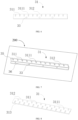
FIG. 1 is a schematic diagram of an insertion-plate-type heat exchanger in the present application. -
FIG. 2 is a schematic diagram of a fixing structure of a first embodiment in the present application. -
FIG. 3 is a schematic diagram of a fixing structure of a second embodiment in the present application. -
FIG. 4 is a schematic diagram of a fixing structure of a third embodiment in the present application. -
FIG. 5 is a schematic diagram of a fixing structure of a fourth embodiment in the present application. -
FIG. 6 is a schematic diagram of a side plate of a first embodiment in the present application. -
FIG. 7 is a schematic diagram of a side plate of a second embodiment in the present application. -
FIG. 8 is a schematic diagram of a side plate of a third embodiment in the present application. -
FIG. 9 is a schematic diagram of a side plate of a fourth embodiment in the present application. -
FIG. 10 is a schematic diagram of a side plate of a fifth embodiment in the present application. -
FIG. 11 is a schematic diagram of a side plate of a sixth embodiment in the present application. -
FIG. 12 is a schematic diagram of a side plate of a seventh embodiment in the present application. -
FIG. 13 is a schematic diagram of a side plate of an eight embodiment in the present application. -
FIG. 14 is a schematic diagram of a connection structure of a side plate in the present application. - Reference signs are as follows: 100 represents an insertion-plate-type heat exchanger; 200 represents an external machine; 10 represents an insertion plate; 20 represents a heat exchanger tube; 30 represents a fixing structure; 31 represent a side plate; 311 represents an inserting hole; 3111 represents an opening portion; 312 represents a first edge portion; 313 represents a second edge portion; 314 represents a first inserting hole; 315 represents a second inserting hole; 32 represents an end plate; 33 represents an installing hole; 34 represents a connecting component; 341 represents a connecting plate; 342 represents a fastener; 35 represent a first fixing portion; 36 represents a second fixing portion; 40 represents a middle plate; 50 represents an elbow; 60 represents a distributor; 70 represents a capillary tube; 80 represents a connecting pipe; and 90 represents a collecting pipe.
- In order to make above objectives, features, and advantages of the present application more obvious and understandable, a detailed explanation of the specific implementation of the present application will be provided below in combination with drawings. Many specific details are elaborated in following description to facilitate a thorough understanding of the present application. A specific implementation described here is only for the purpose of explaining the present application and does not limit a scope of protection of the present application.
- It should be noted that, when a component is considered "mounted on" or "disposed on" another component, it can be directly disposed on another component or there may be a centered component present simultaneously. When a component is considered "fixed on" another component, it can be directly fixed on another component or there may be a centered component present simultaneously. The terms "vertical", "horizontal", "left", "right" and similar expressions used in the specification of the present application are for illustrative purposes only and do not represent the only implementation method.
- Unless otherwise defined, all technical and scientific terms used in this article have the same meanings as those commonly understood by those skilled in the art of the present application. The terms used in the specification of the present application are only for the purpose of describing specific embodiments and are not intended to limit the present application. The term "and/or" used in this article includes any and all combinations of one or more related listed items.
- Referring to
FIGs. 1 to 14 , an insertion-plate-type heat exchanger 100 is usually applied to an air conditioning system, and the insertion-plate-type heat exchanger 100 is a most used heat exchanger apparatus in a gas and liquid heat exchanger, which achieves a purpose of enhancing heat exchange by installing aninsertion plate 10 on aheat exchange tube 20. - In related art, in an installation process of an insertion-plate-type heat exchanger and an external machine, a bracket of an insertion-plate-type heat exchanger is usually connected to a sheet metal part of the external machine. However, since the bracket is welded to a collecting pipe of a microchannel heat exchanger product, furnace brazing causes expansion and contraction in longitudinal and vertical directions of a product, so that an installing hole on the bracket enlarges or shrinks correspondingly, resulting in assembly errors and failure of installation between the insertion-plate-type heat exchanger product and the sheet metal part of the external machine, increasing batch rejection percentage of the insertion-plate-type heat exchanger, and causing difficulties in an installation between the insertion-plate-type heat exchanger and the external machine.
- In the present application, a fixing
structure 30 is provided and applied to the insertion-plate-type heat exchanger 100. The insertion-plate-type heat exchanger 100 includes a plurality ofheat exchanger tubes 20 and a plurality ofinsertion plates 10. The plurality ofheat exchanger tubes 20 are inserted into the plurality ofinsertion plates 10 along a direction perpendicular to an extending direction of each of the plurality ofinsertion plates 10. The fixingstructure 30 is located on a side surface and/or an end surface of the insertion-plate-type heat exchanger. The fixingstructure 30 includes a first fixingportion 35 and asecond fixing portion 36 connected to each other. Thefirst fixing portion 35 is fixedly connected to the plurality ofheat exchanger tubes 20, and the second fixingportion 36 is fixedly connected to anexternal machine 200. - In the present application, the first fixing
portion 35 is fixedly connected to the plurality ofheat exchanger tubes 20, and the second fixingportion 36 is fixedly connected to theexternal machine 200, facilitating installing the insertion-plate-type heat exchanger 100 on theexternal machine 200 via the fixingstructure 30, improving installation flexibly of the insertion-plate-type heat exchanger 100, and having a wider application. - In one embodiment, the fixing
structure 30 is located on a side surface of the insertion-plate-type heat exchanger 100. The fixingstructure 30 includes aside plate 31, and theside plate 31 is connected to the side surface of the insertion-plate-type heat exchanger 100. - In one embodiment, the fixing
structure 30 is located on an end surface of the insertion-plate-type heat exchanger 100. The fixingstructure 30 includes anend plate 32, and theend plate 32 is connected to the end surface of the insertion-plate-type heat exchanger 100. - In one embodiment, the fixing
structure 30 is located on a side surface and an end surface of the insertion-plate-type heat exchanger 100. The fixingstructure 30 includes aside plate 31 and anend plate 32. Theside plate 31 is connected to the side surface of the insertion-plate-type heat exchanger 100, and theend plate 32 is connected to the end surface of the insertion-plate-type heat exchanger 100. - In above embodiment, the
side plate 31 and theend plate 32 are an integral structure. - To avoid a phenomenon that the plurality of
heat exchanger tubes 20 and the plurality ofinsertion plates 10 are prone to displacement and deformation since no fixing structure is provided for protecting an insertion-plate-type heat exchanger 100, , the fixingstructure 30 is provided in the present application. The fixingstructure 30 is fixedly connected to the insertion-plate-type heat exchanger 100 and disposed around a periphery of the insertion-plate-type heat exchanger 100. The insertion-plate-type heat exchanger 100 includes the side surface and the end surface, and the fixingstructure 30 includes theside plate 31 and theend plate 32. Theside plate 31 is connected to the side surface of the insertion-plate-type heat exchanger 100, and theend plate 32 is connected to the end surface of the insertion-plate-type heat exchanger 100. In order to reduce connection processes between theside plate 31 and theend plate 32, theside plate 31 and theend plate 32 can be formed integrally, in which welding, riveting and other processes are eliminated, and theside plate 31 and theend plate 32 are stamped and formed integrally, improving an production efficiency, so that the insertion-plate-type heat exchanger 100 is firmer, and a service life of the insertion-plate-type heat exchanger 100 is prolonged. - In the present application, the fixing
structure 30 can be connected to the side surface of the insertion-plate-type heat exchanger 100, the end surface of the insertion-plate-type heat exchanger 100, or both the side surface and the end surface of the insertion-plate-type heat exchanger 100. Subsequent descriptions of specific structures of theside plate 31 and theend plate 32 can be based on the above description. - Referring to
FIG. 1 , the insertion-plate-type heat exchanger 100 further includes anelbow 50, adistributor 60, acapillary tube 70, a connectingpipe 80 and a collectingpipe 90. Two ends of theelbow 50 are connected to any two of the plurality ofheat exchanger tubes 20, respectively. One end of thecapillary tube 70 is connected to thedistributor 60 and the other end of thecapillary tube 70 is connected to theheat exchanger tube 20. One end of the connectingpipe 80 is connected to the collectingpipe 90 and the other end of the connectingpipe 80 is connected to each of plurality of theheat exchanger tube 20. - Referring to
FIGs. 2 to 5 , the insertion-plate-type heat exchanger 100 includes two side surfaces and two end surfaces, which are a top end surface, a bottom end surface, a left side surface and a right side surface, respectively. Therefore, methods of arranging the fixingstructure 30 can be diverse. - Referring to
FIG. 2 , in the fixingstructure 30 of a first embodiment, theside plate 31 and theend plate 32 are in an L shape, i.e., the number of theside plate 31 is one and the number of theend plate 32 is one. In other words, in the fixingstructure 30 of the first embodiment, several connection types are described as follows: theside plate 31 and theend plate 32 can be connected to the left side surface and the bottom end surface, respectively; or, theside plate 31 and theend plate 32 can be connected to the left side surface and the top end surface, respectively; or, theside plate 31 and theend plate 32 can be connected to the right side surface and the bottom end surface, respectively; or, theside plate 31 and theend plate 32 can be connected to the right side surface and the top end surface, respectively. - Referring to
FIG. 3 , in the fixingstructure 30 of a second embodiment, theside plate 31 and theend plate 32 is in a shape ofor , i.e., the number of the
side plate 31 is two and the number of theend plate 32 is one. In other word, in the fixingstructure 30 of the second embodiment, several connection types are described as follows: twoside plates 31 and oneend plate 32 are connected to the left side surface, the right side surface and the bottom end surface, respectively, or, twoside plates 31 and oneend plate 32 are connected to the left side surface, the right side surface and the top end surface, respectively. - Referring to
FIG. 4 , in the fixingstructure 30 of a third embodiment, theside plate 31 and theend plate 32 is in a shape of , i.e., the number of theside plate 31 is one and the number of theend plate 32 is two. In other words, in the fixingstructure 30 of the third embodiment, several connection types are described as follows: oneside plate 31 and twoend plates 32 are connected to the left side surface, the top end surface and the bottom end surface, respectively; or, oneside plate 31 and twoend plates 32 are connected to the right side surface, the top end surface and the bottom end surface, respectively. - Referring to
FIG. 5 , in the fixingstructure 30 of a fourth embodiment, theside plate 31 and theend plate 32 is in a frame shape to form a rectangular or square shape □, i.e., the number of theside plate 31 is two and the number ofend plate 32 is two. In other words, in the fixingstructure 30 of the fourth embodiment, the fixingstructure 30 is disposed around the insertion-plate-type heat exchanger 100, i.e., the top end surface, the bottom end surface, the left side surface, and the right side surface. - The
side plate 31 and theend plate 32 are not limited by being perpendicular to each other. Alternatively, an acute angle or an obtuse angle can be defined between theside plate 31 and theend plate 32, which is not limited herein. - Since the plurality of
heat exchanger tubes 20 extends along an axis of theend plate 32, theside plate 31 is perpendicular to the plurality ofheat exchanger tubes 20 along an extending direction of each of the plurality ofheat exchanger tubes 20. Therefore, theside plate 31 is required to be fixedly connected to the side surface of the insertion-plate-type heat exchanger 100, and the plurality ofheat exchanger tubes 20 are required to be inserted into theside plate 31, such that each of the plurality ofheat exchanger tubes 20 can be further fixed. - Referring to
FIGs. 6 to 14 , the fixingstructure 30 is located on the side surface of the insertion-plate-type heat exchanger 100. The fixingstructure 30 includes theside plate 31. Theside plate 31 is connected to the side surface of the insertion-plate-type heat exchanger 100. Theside plate 31 is provided with a plurality of insertingholes 311 corresponding to the plurality ofheat exchanger tubes 20. The plurality ofheat exchanger tubes 20 are inserted into the plurality of insertingholes 311. When theside plate 31 is installed on the side surface of the insertion-plate-type heat exchanger 100, the plurality ofheat exchanger tubes 20 are inserted into the plurality of insertingholes 311 and fixedly connected to theside plate 31 by the plurality of insertingholes 311, thereby fixing the plurality ofheat exchanger tubes 20, and preventing displacement and friction between the plurality ofheat exchanger tubes 20 and the plurality ofinsertion plates 10. - Methods of disposing the plurality of inserting
holes 311 on theside plate 31 are diverse. For example, theside plate 31 is provided with afirst edge portion 312. At least one of the plurality of insertingholes 311 passes through thefirst edge portion 312 to define anopening 3111, i.e., the insertinghole 311 passes through the side plate 31 (as shown in the first embodiment ofFIG. 6 , the second embodiment ofFIG. 7 , the third embodiment ofFIG. 8 , the fourth embodiment ofFIG. 9 , the seventh embodiment ofFIG. 12 , and the eighth embodiment ofFIG. 13 ). For example, two sides of theside plate 31 include afirst edge portion 312 and asecond edge portion 313, respectively. A side wall of the insertinghole 311 is spaced from thefirst edge portion 312 and thesecond edge portion 313, i.e., the plurality of insertingholes 311 are sealed on the side plate 31 (as shown in a fifth embodiment ofFIG. 10 ). For example, the two sides of theside plate 31 include thefirst edge portion 312 and thesecond edge portion 313, respectively. Each of the plurality of insertingholes 311 includes a first insertinghole 314 and a second insertinghole 315. The first insertinghole 314 passes through thefirst edge portion 312 and/or thesecond edge 313 to define anopening 3111. A side wall of the second insertinghole 315 is spaced from thefirst edge portion 312 and thesecond edge portion 313, i.e., a part of the insertinghole 311 passes through theside plate 31 and sealed on the side plate 31 (as shown in the sixth embodiment ofFIG. 11 ), and in this embodiment, the number of rows of first insertinghole 314 can be one or two, when the number of the rows of the first insertinghole 314 is one, at least one insertinghole 311 passes through thefirst edge portion 312 or thesecond edge portion 313 to define anopening 3111, and when the number of the rows of first insertingholes 314 is two, one row of the first insertinghole 314 passes through thefirst edge portion 312, the other row of the first insertinghole 314 passes through thesecond edge portion 313. The number of rows of second insertinghole 315 can be one row or multiple. - Methods of disposing the
side plate 31 are diverse. For example, the first fixingportion 35 and the second fixingportion 36 connected to each other are disposed in theside plate 31. Thesecond fixing portion 36 is bent relative to the first fixing portion 35 (as shown in the second embodiment ofFIG. 7 , the fourth embodiment ofFIG. 9 and the eighth embodiment ofFIG. 13 ). For example, theside plate 31 is in a plate shape (as shown in the first embodiment ofFIG. 6 , the third embodiment ofFIG. 8 , the fifth embodiment ofFIG. 10 , th sixth embodiment ofFIG. 11 , and the seventh embodiment ofFIG. 12 ). - A plurality of inserting
holes 311 are arranged along an axis of theside plate 31 to form one row of the insertinghole 311. The plurality of insertingholes 311 on theside plate 31 can be arranged in one row, two rows, three rows, four rows or a plurality of rows according to the number of the rows of the plurality of insertingholes 100. - In order to facilitate inserting the plurality of
heat exchanger tubes 20 into the plurality of insertingholes 311, a size of theopening 3111 is greater than a size of an end of the at least one of the plurality of insertingholes 311 away from the first edge portion. It is conducive to snapping and positioning the plurality ofheat exchanger tubes 20. - In particular, when two or more rows of the plurality of inserting
holes 311 are disposed on theside plate 31, the plurality of insertingholes 311 pass through thefirst edge portion 312 or thesecond edge portion 313 to define theopening 3111. In order to facilitate inserting the plurality ofheat exchanger tubes 20, sizes of at least two of plurality of insertingholes 311 are different along a direction of each of the plurality ofheat exchanger tubes 20 inserted into one of the plurality of insertingholes 311. It is conducive to realizing a connection between the plurality of insertingholes 311 and the plurality ofheat exchanger tubes 20, thereby improving a compatibility performance of theside plate 31 for the plurality ofheat exchanger tubes 20. - Furthermore, the fixing
structure 30 is further provided with an installinghole 33, the installinghole 33 can allow theexternal machine 200 to be fixedly connected to the fixingstructure 30 through the installinghole 33. When theside plate 31 is in a plate shape, the installinghole 33 can be disposed on theside plate 31 in the plate shape. When theside plate 31 is bent, the installinghole 33 can be disposed on the second fixingportion 36. Alternatively, the installinghole 33 cannot be disposed on theside plate 31 and can be disposed on theend plate 32, as long as the installinghole 33 can allow theexternal machine 200 to be fixedly connected to the fixingstructure 30 through the installinghole 33, which is not limited herein. - Referring to
FIG. 6 , in the first embodiment, theside plate 31 is in the plate shape, the plurality of insertingholes 311 on theside plate 31 are arranged in one row. The plurality of insertingholes 311 pass through theside plate 31, and the plurality of installingholes 33 are disposed on a part of theside plate 31 where no insertinghole 311 is provided. - Referring to
FIG. 7 , in the second embodiment, theside plate 31 is bent, the plurality of insertingholes 311 is arranged in one row. The plurality of insertingholes 311 pass through the first fixingportion 35, facilitating assembling the plurality of installingholes 311 and the plurality ofheat exchanger tubes 20, and the installinghole 33 is disposed on the second fixingportion 36. - Referring to
FIG. 8 , in the third embodiment, theside plate 31 is in a plate shape, the plurality of insertingholes 311 on theside plate 31 are arranged in two rows. The plurality of insertingholes 311 pass through theside plate 31, the plurality of insertingholes 311 arranged in the two rows pass through thefirst edge portion 312 or thesecond edge portion 313 to define a plurality ofopenings 3111, and no installinghole 33 is provided on theside plate 31. - Referring to
FIG. 9 , in the fourth embodiment, theside plate 31 is bent. The plurality of insertingholes 311 on theside plate 31 are arranged in two rows. The plurality of insertingholes 311 arranged in the two rows pass through thefirst edge portion 312 or thesecond edge portion 313 to define the plurality ofopenings 3111. The installinghole 33 is disposed on the second fixingportion 36. - Referring to
FIG. 10 , in the fifth embodiment, theside plate 31 is in a plate shape, the plurality of insertingholes 311 are arranged in four rows. The plurality of insertingholes 311 are arranged on theside plate 31, and the side wall of each of the plurality of insertingholes 311 is spaced from with thefirst edge portion 312 and thesecond edge portion 313. No installinghole 33 is provided on theside plate 31. - Referring to
FIG. 11 , in the sixth embodiment, theside plate 31 is in a plate shape, the plurality of insertingholes 311 are arranged in four rows. Two rows of the plurality of first insertingholes 314 towards thefirst edge portion 312 and thesecond edge portion 313 pass through theside plate 31, and the other two rows of the plurality of second insertinghole 315 away from thefirst edge portion 312 and thesecond edge portion 313 are arranged on theside plate 31 and spaced from thefirst edge portion 312 and thesecond edge portion 313. No installinghole 33 is provided on theside plate 31. - Referring to
FIG. 12 , in the seventh embodiment, theside plate 31 is in a plate shape, the plurality of insertingholes 311 on theside plate 31 are arranged in two rows. The plurality of insertingholes 311 pass through theside plate 31. The sizes of at least two of the plurality of insertingholes 311 are different, the plurality of insertingholes 311 are not required to be corresponding to the plurality ofheat exchanger tubes 20 one by one for assembly during an installation between theside plate 31 and the plurality ofheat exchanger tubes 20. Theside plate 31 is mounted with the plurality ofheat exchanger tubes 20 by a snapping method. Theside plate 31 is detachable from theheat exchanger tubes 20. No installinghole 33 is provided on theside plate 31. - Referring to
FIG. 13 , in the eighth embodiment, theside plate 31 is bent, the plurality of insertinghole 311 on theside plate 31 is arranged in one row. The plurality of insertingholes 311 pass through theside plate 31. A size of theopening 3111 is greater than a size of an end of the at least one of the plurality of insertingholes 311 away from thefirst edge portion 312. The installinghole 33 is disposed on the second fixingportion 36. - The above embodiments can be combined with each other to form new embodiments, which are not limited herein.
- Referring to
FIG. 14 , when the number of rows of insertion-plate-type heat exchanger 100 is multiple. The number of theside plates 31 located on the same side of the insertion-plate-type heat exchanger 100 is multiple. Aconnection plate 34 is connected between adjacent two of a plurality ofside plates 31. The connectingcomponent 34 includes aconnection plate 341 and afastener 342. Two ends of theconnection plate 341 are connected to the adjacent two of the plurality ofside plates 31, respectively. Thefastener 342 penetrates through theconnection plate 341 and thecorresponding side plate 31 to connect theconnection plate 341 and thecorresponding side plates 31, facilitating assembling the plurality ofside plates 31 to adapt a plurality of rows of the insertion-plate-type heat exchanger 100. - Furthermore, the insertion-plate-
type heat exchanger 100 further includes amiddle plate 40. The insertion-plate-type heat exchanger 100 is more stable by arranging themiddle plate 40. During a process of transportation, installation, and use, the plurality ofheat exchanger tubes 20 and the plurality ofinsertion plates 10 can be protected, which is not prone to deformation and displacement, resulting in prolonging a service life of the insertion-plate-type heat exchanger 100. - In particular, the
middle plate 40 is disposed between two side surfaces of the insertion-plate-type heat exchanger 100. A distance between themiddle plate 40 and theside plate 31 is in a range of 250 mm to 900 mm, i.e., the distance between themiddle plate 40 and theside plate 31 can be 250 mm, 400 mm, 600 mm, 800mm, 900 mm and any value in a range of 250 mm to 900 mm, which is not limited herein. - A plurality of
middle plates 40 can be disposed between two sides of the insertion-plate-type heat exchanger 100. A distance between adjacent two of the plurality ofmiddle plates 40 can be in a range of 250 mm to 900 mm, i.e., the distance between adjacent two of the plurality ofmiddle plates 40 can be 250 mm, 400 mm, 600 mm, 800 mm, 900 mm and any value in the range of 250 mm to 900 mm, which is not limited herein. - In the fixing
structure 30 provided by the present application, the first fixingportion 35 is fixedly connected to the plurality ofheat exchanger tubes 20, the second fixingportion 36 is fixedly connected to theexternal machine 200, facilitating installing the insertion-plate-type heat exchanger 100 on theexternal machine 200 by the fixingstructure 30, improving the installation flexibly of the insertion-plate-type heat exchanger 100, and having the wider application. - The various technical features of the above embodiments can be combined in any way. In order to make the description concise, not all possible combinations of the various technical features in the above embodiments have been described. However, as long as there is no contradiction in the combination of these technical features, they should be considered within the scope of the specification.
- The above embodiments only express several embodiments of the present application, and their descriptions are more specific and detailed, but should not be understood as limiting the scope of the disclosure. It should be pointed out that for ordinary skill in the art, several modifications and improvements can be made without departing from the concept of the disclosure, which are within the scope of protection of the disclosure. Therefore, the scope of protection of the present application should be based on the attached claims.
Claims (15)
- A fixing structure applied to an insertion-plate-type heat exchanger, wherein the insertion-plate-type heat exchanger comprises a plurality of heat exchanger tubes and a plurality of insertion plates, the plurality of heat exchanger tubes are inserted into the plurality of insertion plates along a direction perpendicular to an extending direction of each of the plurality of insertion plates, the fixing structure is located on a side surface and/or an end surface of the insertion-plate-type heat exchanger; and
the fixing structure comprises a first fixing portion and a second fixing portion connected to each other, the first fixing portion is fixedly connected to the plurality of heat exchanger tubes, and the second fixing portion is fixedly connected to an external machine. - The fixing structure of claim 1, wherein the fixing structure is located on the side surface and the end surface of the insertion-plate-type heat exchanger, the fixing structure comprises a side plate and an end plate, the side plate is connected to the side surface of the insertion-plate-type heat exchanger, the end plate is connected to the end surface of the insertion-plate-type heat exchanger, and the side plate and the end plate are an integral structure.
- The fixing structure of claim 2, wherein the number of the side plate is one, the number of the end plate is one;or the number of the side plate is two, the number of the end plate is one;or the number of the side plate is one, the number of the end plate is two;or the number of the side plate is two, the number of the end plate is two.
- The fixing structure of claim 1, wherein the fixing structure is located on the side surface of the insertion-plate-type heat exchanger, the fixing structure comprises a side plate, the side plate is located on the side surface of the insertion-plate-type heat exchanger, the side plate is provided with a plurality of inserting holes corresponding to the plurality of heat exchanger tubes, and the plurality of heat exchanger tubes are inserted into the plurality of inserting holes.
- The fixing structure of claims 2 or 4, wherein the side plate is provided with a plurality of inserting holes corresponding to the plurality of heat exchanger tubes, the plurality of heat exchanger tubes are inserted into the plurality of inserting holes; and
the side plate is further provided with a first edge portion, at least one of the plurality of inserting holes passes through the first edge portion to define an opening. - The fixing structure of claim 5, wherein along a direction of each of plurality of the heat exchanger tubes inserted into one of the plurality of inserting holes, sizes of at least two of the plurality of inserting holes are different.
- The fixing structure of claim 5, wherein a size of the opening is greater than a size of an end of the at least one of the plurality of inserting holes away from the first edge portion.
- The fixing structure of claims 2 or 4 , wherein the side plate is provided with a plurality of inserting holes corresponding to the plurality of heat exchanger tubes, the plurality of heat exchanger tubes are inserted into the plurality of inserting holes; and
two sides of the side plate comprise a first edge portion and a second edge portion, respectively, a side wall of each of the plurality of inserting holes is spaced from the first edge portion and the second edge portion. - The fixing structure of claims 2 or 4, wherein the side plate is provided with a plurality of inserting holes corresponding to the plurality of heat exchanger tubes, the plurality of heat exchanger tubes are inserted into the plurality of inserting holes; and
two sides of the side plate comprise a first edge portion and a second edge portion, respectively, each of the plurality of inserting holes comprises a first inserting hole and a second inserting hole, the first inserting hole passes through the first edge portion and/or the second edge portion to define an opening, a side wall of the second inserting hole is spaced from the first edge portion and the second edge portion. - The fixing structure of claim 2, wherein the first fixing portion and the second fixing portion are disposed in the side plate and/or the end plate, and the second fixing portion is bent relative to the first fixing portion.
- The fixing structure of claim 1, wherein the second fixing portion is provided with an installing hole, and the installing hole is configured for allowing the external machine to be fixedly connected to the second fixing portion through the installing hole.
- The fixing structure of claims 2 or 4, wherein the number of the side plate located on the same side of the insertion-plate-type heat exchanger is multiple, a connecting component is disposed between adjacent two of a plurality of side plates, the connecting component comprises a connecting plate and a fastener, two ends of the connecting plate are connected to the adjacent two of the plurality of side plates, respectively, the fastener penetrates through the connecting plate and the corresponding side plate to connect the connecting plate and the corresponding side plate.
- An insertion-plate-type heat exchanger comprising a plurality of heat exchanger tubes, a plurality of insertion plates and a fixing structure,wherein the insertion-plate-type heat exchanger comprises the plurality of heat exchanger tubes and the plurality of insertion plates, the plurality of heat exchanger tubes are inserted into the plurality of insertion plates along a direction perpendicular to an extending direction of each of the plurality of insertion plates, the fixing structure is located on a side surface and/or an end surface of the insertion-plate-type heat exchanger; andthe fixing structure comprises a first fixing portion and a second fixing portion connected to each other, the first fixing portion is fixedly connected to the plurality of heat exchanger tubes, and the second fixing portion is fixedly connected to an external machine,the plurality of heat exchanger tubes are inserted into the plurality of insertion plates along a direction perpendicular to an extending direction of each of the plurality of insertion plates, the fixing structure is located on a side surface and/or an end surface of the insertion-plate-type heat exchanger.
- The insertion-plate-type heat exchanger of claim 13, wherein the fixing structure comprises a side plate connected to the side surface of the insertion-plate-type heat exchanger, the insertion-plate-type heat exchanger further comprises a middle plate, the middle plate is disposed between two side surfaces of the insertion-plate-type heat exchanger, and a distance between the middle plate and the side plate is in a range of 250 mm to 900 mm.
- The insertion-plate-type heat exchanger of claim 14, wherein the number of the middle plate is multiple, and a distance between adiacent two of a plurality of middle plates is in a range of 250 mm to 900 mm.
Applications Claiming Priority (2)
| Application Number | Priority Date | Filing Date | Title |
|---|---|---|---|
| CN202220611840.1U CN217383902U (en) | 2022-03-18 | 2022-03-18 | Fixing structure and inserted sheet type heat exchanger with same |
| PCT/CN2023/072348 WO2023173925A1 (en) | 2022-03-18 | 2023-01-16 | Fixing structure and insertion-plate-type heat exchanger having same |
Publications (2)
| Publication Number | Publication Date |
|---|---|
| EP4481312A1 true EP4481312A1 (en) | 2024-12-25 |
| EP4481312A4 EP4481312A4 (en) | 2025-06-25 |
Family
ID=83102757
Family Applications (1)
| Application Number | Title | Priority Date | Filing Date |
|---|---|---|---|
| EP23769436.9A Pending EP4481312A4 (en) | 2022-03-18 | 2023-01-16 | MOUNTING STRUCTURE AND INSERT PLATE HEAT EXCHANGER SO |
Country Status (4)
| Country | Link |
|---|---|
| US (1) | US20250012522A1 (en) |
| EP (1) | EP4481312A4 (en) |
| CN (1) | CN217383902U (en) |
| WO (1) | WO2023173925A1 (en) |
Families Citing this family (2)
| Publication number | Priority date | Publication date | Assignee | Title |
|---|---|---|---|---|
| CN217383902U (en) * | 2022-03-18 | 2022-09-06 | 浙江盾安热工科技有限公司 | Fixing structure and inserted sheet type heat exchanger with same |
| CN118670157B (en) * | 2024-07-08 | 2024-11-22 | 洛瓦特热交换系统(广东)有限公司 | Energy-saving heat exchange device |
Family Cites Families (15)
| Publication number | Priority date | Publication date | Assignee | Title |
|---|---|---|---|---|
| KR20050062040A (en) * | 2003-12-19 | 2005-06-23 | 삼성전자주식회사 | End-plate for heat-exchanger, heat-exchanger with the end-plate and manufacturing method thereof |
| JP4991904B2 (en) * | 2010-04-26 | 2012-08-08 | シャープ株式会社 | Heat exchanger |
| CN203385180U (en) * | 2013-08-15 | 2014-01-08 | 杭州三花微通道换热器有限公司 | a heat exchanger |
| WO2015061447A2 (en) * | 2013-10-23 | 2015-04-30 | Modine Manufacturing Comapny | Heat exchanger and side plate |
| CN104729156B (en) * | 2013-12-23 | 2020-09-22 | 珠海格力电器股份有限公司 | Heat exchanger assembly and air conditioner |
| CN204461190U (en) * | 2015-01-28 | 2015-07-08 | 格力电器(合肥)有限公司 | Air conditioner, evaporator and sideboard tool |
| CN206037377U (en) * | 2016-08-30 | 2017-03-22 | 芜湖美智空调设备有限公司 | Aluminum pipe heat exchanger and air conditioning equipment |
| CN207865763U (en) * | 2018-01-24 | 2018-09-14 | 固安冰川制冷设备有限公司 | U-shaped finned heat exchanger equipped with middle partition board |
| CN209310598U (en) * | 2018-11-23 | 2019-08-27 | 杭州三花微通道换热器有限公司 | A kind of fin and the heat exchanger with the fin |
| CN214502161U (en) * | 2021-01-18 | 2021-10-26 | 海信(广东)空调有限公司 | Heat Exchangers and Window Air Conditioners |
| CN214501699U (en) * | 2021-02-09 | 2021-10-26 | 海信(广东)空调有限公司 | Heat exchanger and air conditioner with same |
| WO2023097997A1 (en) * | 2021-11-30 | 2023-06-08 | 美的集团武汉制冷设备有限公司 | Heat exchanger mounting structure and air conditioner |
| US12292246B2 (en) * | 2021-12-02 | 2025-05-06 | Tyco Fire & Security Gmbh | Methods of manufacturing heat exchanger systems |
| CN114383435B (en) * | 2021-12-27 | 2023-08-29 | 江西鑫田车业有限公司 | Reinforcing plate for automobile radiator and automobile radiator |
| CN217383902U (en) * | 2022-03-18 | 2022-09-06 | 浙江盾安热工科技有限公司 | Fixing structure and inserted sheet type heat exchanger with same |
-
2022
- 2022-03-18 CN CN202220611840.1U patent/CN217383902U/en active Active
-
2023
- 2023-01-16 WO PCT/CN2023/072348 patent/WO2023173925A1/en not_active Ceased
- 2023-01-16 EP EP23769436.9A patent/EP4481312A4/en active Pending
-
2024
- 2024-09-18 US US18/888,184 patent/US20250012522A1/en active Pending
Also Published As
| Publication number | Publication date |
|---|---|
| WO2023173925A1 (en) | 2023-09-21 |
| EP4481312A4 (en) | 2025-06-25 |
| US20250012522A1 (en) | 2025-01-09 |
| CN217383902U (en) | 2022-09-06 |
Similar Documents
| Publication | Publication Date | Title |
|---|---|---|
| US20250012522A1 (en) | Fixing structure and insertion-plate-type heat exchanger having same | |
| US20200011607A1 (en) | Heat exchanger including heat-transfer-tube unit | |
| EP1962040B1 (en) | Bend relief spacer | |
| EP3040667B1 (en) | Heat exchanger | |
| US20070131404A1 (en) | Heat exchanger | |
| EP3505848B1 (en) | Heat exchanger, heat exchanger module, and air conditioning system | |
| EP1710527B1 (en) | Support for heat exchanger tubes | |
| EP3657117B1 (en) | Heat-exchanger manufacturing method, heat-exchanger overlaying method, heat exchanger and multi-row heat exchanger | |
| US11480348B2 (en) | Heat exchanger | |
| US12504099B2 (en) | Pipe clamp assembly and heat exchanger having same | |
| CN216745669U (en) | Fin structure and heat exchanger | |
| CN115790218A (en) | Finned heat pipe heat exchanger | |
| CN218270306U (en) | Anti-vibration structure of U-shaped pipe bundle bend section | |
| US20090032230A1 (en) | Support plate for separate and independent tube bundles | |
| US20050109494A1 (en) | Heat exchanger tube support | |
| CN219347481U (en) | Fin and heat exchanger with same | |
| EP1517108B1 (en) | A heat exchanger | |
| CN211876843U (en) | Heat exchanger connecting device and heat exchanger | |
| US20050082050A1 (en) | Multiple row heat exchanger using ''end-to-end'' or ''tube touching'' positioning of the tubes for row spacing | |
| CN212109070U (en) | Heat exchanger | |
| CN219776468U (en) | Spliced end plate structure | |
| EP0777097A1 (en) | A heat exchanger, in particular a radiator for a vehicle, provided with a strengthening structure | |
| CN219368480U (en) | Heat exchanger | |
| CN222257840U (en) | Long hole type baffle plate assembly and shell-and-tube heat exchanger | |
| CN219415883U (en) | Novel mainboard structure and radiator |
Legal Events
| Date | Code | Title | Description |
|---|---|---|---|
| STAA | Information on the status of an ep patent application or granted ep patent |
Free format text: STATUS: THE INTERNATIONAL PUBLICATION HAS BEEN MADE |
|
| PUAI | Public reference made under article 153(3) epc to a published international application that has entered the european phase |
Free format text: ORIGINAL CODE: 0009012 |
|
| STAA | Information on the status of an ep patent application or granted ep patent |
Free format text: STATUS: REQUEST FOR EXAMINATION WAS MADE |
|
| 17P | Request for examination filed |
Effective date: 20240920 |
|
| AK | Designated contracting states |
Kind code of ref document: A1 Designated state(s): AL AT BE BG CH CY CZ DE DK EE ES FI FR GB GR HR HU IE IS IT LI LT LU LV MC ME MK MT NL NO PL PT RO RS SE SI SK SM TR |
|
| A4 | Supplementary search report drawn up and despatched |
Effective date: 20250526 |
|
| DAV | Request for validation of the european patent (deleted) | ||
| DAX | Request for extension of the european patent (deleted) | ||
| RIC1 | Information provided on ipc code assigned before grant |
Ipc: F28F 9/02 20060101ALI20250520BHEP Ipc: F28F 9/00 20060101ALI20250520BHEP Ipc: F28F 1/32 20060101ALI20250520BHEP Ipc: F28F 9/013 20060101ALI20250520BHEP Ipc: F28D 1/047 20060101ALI20250520BHEP Ipc: F28F 9/26 20060101ALI20250520BHEP Ipc: F28D 9/00 20060101AFI20250520BHEP |