EP4481291A1 - Air-conditioning system - Google Patents
Air-conditioning system Download PDFInfo
- Publication number
- EP4481291A1 EP4481291A1 EP23756312.7A EP23756312A EP4481291A1 EP 4481291 A1 EP4481291 A1 EP 4481291A1 EP 23756312 A EP23756312 A EP 23756312A EP 4481291 A1 EP4481291 A1 EP 4481291A1
- Authority
- EP
- European Patent Office
- Prior art keywords
- communication
- accessory device
- air conditioner
- power supply
- air conditioning
- Prior art date
- Legal status (The legal status is an assumption and is not a legal conclusion. Google has not performed a legal analysis and makes no representation as to the accuracy of the status listed.)
- Pending
Links
Images


Classifications
-
- F—MECHANICAL ENGINEERING; LIGHTING; HEATING; WEAPONS; BLASTING
- F24—HEATING; RANGES; VENTILATING
- F24F—AIR-CONDITIONING; AIR-HUMIDIFICATION; VENTILATION; USE OF AIR CURRENTS FOR SCREENING
- F24F11/00—Control or safety arrangements
- F24F11/88—Electrical aspects, e.g. circuits
-
- F—MECHANICAL ENGINEERING; LIGHTING; HEATING; WEAPONS; BLASTING
- F24—HEATING; RANGES; VENTILATING
- F24F—AIR-CONDITIONING; AIR-HUMIDIFICATION; VENTILATION; USE OF AIR CURRENTS FOR SCREENING
- F24F11/00—Control or safety arrangements
- F24F11/50—Control or safety arrangements characterised by user interfaces or communication
-
- F—MECHANICAL ENGINEERING; LIGHTING; HEATING; WEAPONS; BLASTING
- F24—HEATING; RANGES; VENTILATING
- F24F—AIR-CONDITIONING; AIR-HUMIDIFICATION; VENTILATION; USE OF AIR CURRENTS FOR SCREENING
- F24F11/00—Control or safety arrangements
- F24F11/50—Control or safety arrangements characterised by user interfaces or communication
- F24F11/54—Control or safety arrangements characterised by user interfaces or communication using one central controller connected to several sub-controllers
-
- F—MECHANICAL ENGINEERING; LIGHTING; HEATING; WEAPONS; BLASTING
- F24—HEATING; RANGES; VENTILATING
- F24F—AIR-CONDITIONING; AIR-HUMIDIFICATION; VENTILATION; USE OF AIR CURRENTS FOR SCREENING
- F24F11/00—Control or safety arrangements
- F24F11/50—Control or safety arrangements characterised by user interfaces or communication
- F24F11/56—Remote control
-
- F—MECHANICAL ENGINEERING; LIGHTING; HEATING; WEAPONS; BLASTING
- F24—HEATING; RANGES; VENTILATING
- F24F—AIR-CONDITIONING; AIR-HUMIDIFICATION; VENTILATION; USE OF AIR CURRENTS FOR SCREENING
- F24F11/00—Control or safety arrangements
- F24F11/62—Control or safety arrangements characterised by the type of control or by internal processing, e.g. using fuzzy logic, adaptive control or estimation of values
- F24F11/63—Electronic processing
-
- F—MECHANICAL ENGINEERING; LIGHTING; HEATING; WEAPONS; BLASTING
- F24—HEATING; RANGES; VENTILATING
- F24F—AIR-CONDITIONING; AIR-HUMIDIFICATION; VENTILATION; USE OF AIR CURRENTS FOR SCREENING
- F24F11/00—Control or safety arrangements
- F24F11/89—Arrangement or mounting of control or safety devices
-
- H—ELECTRICITY
- H04—ELECTRIC COMMUNICATION TECHNIQUE
- H04B—TRANSMISSION
- H04B3/00—Line transmission systems
- H04B3/54—Systems for transmission via power distribution lines
-
- F—MECHANICAL ENGINEERING; LIGHTING; HEATING; WEAPONS; BLASTING
- F24—HEATING; RANGES; VENTILATING
- F24F—AIR-CONDITIONING; AIR-HUMIDIFICATION; VENTILATION; USE OF AIR CURRENTS FOR SCREENING
- F24F11/00—Control or safety arrangements
- F24F11/50—Control or safety arrangements characterised by user interfaces or communication
- F24F11/56—Remote control
- F24F11/58—Remote control using Internet communication
Definitions
- the present disclosure relates to an air conditioning system including an air conditioner and an accessory device driven by power supplied from the air conditioner.
- connection of devices may be confirmed and the devices may be communicated with each other by using a low frequency signal and a high frequency signal.
- Patent Literature 1 when a communication method used for a large device such as an outdoor unit and an indoor unit is applied to communication between an air conditioner and an accessory device, downsizing of the accessory device becomes difficult. Therefore, in a configuration in which communication and power supply are performed between the air conditioner and the accessory device by current loop communication using a power supply wiring, the size of an electric component for separating a power source and a communication signal and the like hinder downsizing of the accessory device.
- An air conditioning system including an accessory device supplied with power from an air conditioner has a problem of downsizing the accessory device.
- An air conditioning system includes an air conditioner, an accessory device driven by power supplied from the air conditioner, a power supply wiring, a first communication device, a second communication device, and a controller.
- the power supply wiring supplies power from the air conditioner to the accessory device.
- a first communication device changes a current flowing through the power supply wiring and performs current loop communication between the air conditioner and the accessory device.
- a second communication device superimposes a voltage signal on the power supply wiring and performs communication between the air conditioner and the accessory device.
- a controller controls the first communication device and the second communication device.
- the air conditioning system can use the current loop communication for recognizing the accessory device and use the voltage signal for data communication.
- the components of the accessory device can be easily downsized, and the accessory device can be easily downsized.
- An air conditioning system is the system according to the first aspect, in which the current loop communication of the first communication device is performed by turning on and off the current flowing through the power supply wiring.
- An air conditioning system is the system according to the first or second aspect, in which a frequency of the voltage signal of the second communication device is higher than a frequency of the current loop communication of the first communication device.
- the air conditioning system can perform communication in which crosstalk is less likely to occur than the second communication device by using the first communication device, and can transfer more data faster than the first communication device by using the second communication device.
- An air conditioning system is the system according to any one of the first to third aspects, in which the controller configures a communication network by determining, using the current loop communication, that the accessory device is connected, and performs data communication by the voltage signal after the configuration of the communication network.
- An air conditioning system is the system according to the fourth aspect, in which by sequentially causing the second communication device to perform transmission and reception, the first communication device to perform transmission and reception, and the second communication device to perform transmission and reception between the air conditioner and the accessory device, the controller determines that the accessory device is connected, and configures the communication network.
- the voltage signals are transmitted and received before and after the current loop communication during the configuration of the communication network, it is possible to reliably determine the connection of the accessory device in shorter time compared to a case where only one of the communication is used.
- An air conditioning system is the system according to any one of the first to fifth aspects, in which the power supply wiring is a nonpolarized wiring.
- the power supply wiring can be smoothly connected.
- An air conditioning system 1 shown in FIG. 1 includes an air conditioner 2 and an accessory device 3.
- the air conditioner 2 includes an outdoor unit 11 and a plurality of indoor units 12.
- the outdoor unit 11 and the indoor units 12 are connected so as to be communicable with each other, to perform air conditioning of a target space.
- the indoor units 12 of the air conditioner 2 and the accessory device 3 are connected to be communicable with each other, and the accessory device 3 imparts a specific function to the air conditioner 2.
- the accessory device 3 described here is electric equipment that is electrically driven when imparting the specific function to the air conditioner 2.
- the accessory device 3 can impart a function of detecting a specific natural phenomenon or a property of an artifact to the air conditioner 2.
- the sensor as the accessory device 3 detects, for example, a natural phenomenon, a thermal, mechanical, acoustic, electromagnetic, or chemical property of an artifact, or the like and transmits a signal that can be handled by the air conditioner 2 in place of the detection result.
- the accessory device 3 is a remote controller, the accessory device 3 imparts a function of remotely operating the air conditioner 2.
- the outdoor unit 11 is connected to a commercial power source 101 in order to supply power to the outdoor unit 11. Power is supplied to each indoor unit 12 from the commercial power source 101 via the outdoor unit 11 and a power source wiring PSW.
- the commercial power source 101 for driving the outdoor unit 11 and the indoor units 12 is the same system.
- the power source is not required to be the same system and may be the commercial power source 101 for driving the outdoor unit 11 and a commercial power source 102 for driving the indoor unit 12.
- Power is supplied to the accessory device 3 from the indoor units 12 of the air conditioner 2.
- the accessory device 3 is electric equipment driven by power supplied from the air conditioner 2.
- the outdoor unit 11, a first indoor unit 12a, a second indoor unit 12b, and a third indoor unit 12c form a refrigerant circuit RC, which together constitute the core of a single refrigerant system RS.
- the outdoor unit 11, the first indoor unit 12a, the second indoor unit 12b, and the third indoor unit 12c are connected by refrigerant pipes P1 and P2, and the same refrigerant circulates in these outdoor unit 11 and indoor units 12.
- the refrigerant system RS includes not only the outdoor unit 11, the first indoor unit 12a, the second indoor unit 12b, and the third indoor unit 12c but also the accessory device 3 attached to the air conditioner 2.
- the refrigerant system RS may include a control device (not shown) that controls the air conditioner 2. Examples of the control device include a centralized controller that controls the outdoor unit 11, the first indoor unit 12a, the second indoor unit 12b, and the third indoor unit 12c.
- the air conditioning system 1 performs system recognition to identify a system to which a target air conditioner belongs. This is achieved by distinguishing between a group related to the operation of the air conditioner 2 and a group related to the operation of other air conditioners, treating each group as a separate refrigerant system.
- the accessory device 3 is included in the refrigerant system RS to which the refrigerant circuit RC of the air conditioner 2 belongs.
- the outdoor unit 11 of the air conditioner 2 recognizes that the indoor units 12a, 12b, and 12c belong to the same refrigerant system RS.
- the outdoor unit 11 can communicate with the indoor units 12a, 12b, and 12c of the same refrigerant system RS by using the power source wiring PSW.
- the outdoor unit 11 and the indoor units 12a, 12b, and 12c mutually transmit and receive data by communication, so that the outdoor unit 11 and the indoor units 12a, 12b, and 12c can perform air conditioning related to the refrigerant system RS in cooperation.
- the indoor unit 12 and the accessory device 3 mutually transmit and receive data by communication, so that the indoor unit 12 and the accessory device 3 can perform air conditioning related to the refrigerant system RS in cooperation with each other.
- the indoor unit 12 of the air conditioner 2 supplies power to the accessory device 3, and the indoor unit 12 and the accessory device 3 perform current loop communication and high frequency communication by using a power supply wiring W.
- a frequency of a signal transmitted by high frequency communication is higher than a frequency of a signal transmitted by current loop communication.
- the power supply wiring W is a wiring different from the power source wiring PSW that supplies power from the outdoor unit 11 to the indoor unit 12.
- the mode of supplying power from the air conditioner 2 to the accessory device 3 is not limited to the case of supplying power from the indoor unit 12.
- the outdoor unit 11 may be configured to supply power to the accessory device 3 by using a power supply wiring. In this configuration, the outdoor unit 11 and the accessory device 3 may perform the current loop communication and the high frequency communication by using a power supply wiring connecting the outdoor unit 11 and the accessory device 3.
- FIG. 2 shows a configuration related to communication between the air conditioner 2 and the accessory device 3. Specifically, FIG. 2 shows a configuration related to communication between the indoor unit 12 of the air conditioner 2 and the accessory device 3.
- the indoor unit 12 includes a current loop transmitter 21, a first communication driver 31, a first controller 41, a constant voltage source 51, a low pass filter 52, and capacitors 33 and 34.
- the indoor unit 12 includes a DC power source 60 connected to the power source wiring PSW and an internal power source line IL1.
- the DC power source 60 is, for example, a rectifier circuit that generates a DC voltage from the power source wiring PSW.
- the internal power source line IL1 is a line that is connected to the DC power source 60 and supplies DC power to the inside of the indoor unit 12.
- the constant voltage source 51 obtains power from the internal power source line IL1 and generates a constant voltage.
- the indoor unit 12 shown in FIG. 2 uses a Zener diode as the constant voltage source 51.
- the Zener diode is used as the constant voltage source 51 here, the constant voltage source 51 may be configured by using an element or a circuit other than the Zener diode.
- a cathode of the Zener diode is connected to an output terminal OT of the constant voltage source 51, and an anode of the Zener diode is connected to a ground GND.
- the current loop transmitter 21 is connected between the output terminal OT of the constant voltage source 51 and a first line L1 of the power supply wiring W.
- the current loop transmitter 21 transmits a current signal CS by changing a state of connecting the output terminal OT of the constant voltage source 51 and the first line L1.
- the current loop transmitter 21 transmits the current signal CS corresponding to a data signal DS1 provided from the first controller 41.
- the current loop transmitter 21 constitutes a first communication device 20 together with a current loop receiver 22 to be described later.
- the current loop transmitter 21 can be constituted by, for example, a switching element.
- the switching element transmits the current signal CS by switching between a state in which the output terminal OT of the constant voltage source 51 and the first line L1 are connected and a state in which the output terminal OT is not connected in accordance with the data signal DS 1.
- a current flows through the first line L1
- the output terminal OT of the constant voltage source 51 is not connected to the first line L1
- a current does not flow through the first line L1.
- the digital current signal CS is generated by the state in which the current flows and the state in which the current does not flow (by turning on and off the current).
- the switching element includes, for example, a transistor.
- a collector is connected to the output terminal OT of the constant voltage source 51, and an emitter (source) is connected to the first line L1.
- the data signal DS1 is provided from the first controller 41 to a base (gate) of the transistor.
- the low pass filter 52 is inserted into the first line L1 and a second line L2.
- the low pass filter 52 is a filter for removing high-frequency noise generated in the first line L1 and the second line L2.
- the low pass filter 52 can cut off a high frequency signal HF so that the high frequency signal HF provided to the first line L1 and the second line L2 by a second communication device 30 is not transmitted to the constant voltage source 51.
- the first communication driver 31 and the capacitors 33 and 34 constitute a first transceiver of the second communication device 30.
- a second communication driver 32 and capacitors 35 and 36 to be described later constitute a second transceiver of the second communication device 30.
- the second communication device 30 includes the first transceiver (the first communication driver 31 and the capacitors 33 and 34) and the second transceiver (the second communication driver 32 and the capacitors 35 and 36).
- the first communication driver 31 and the capacitors 33 and 34 transmit a voltage signal (high frequency signal HF) by causing a change in voltage between the first line L1 and the second line L2.
- the first communication driver 31 generates a voltage signal corresponding to a data signal DS3 provided from the first controller 41.
- the capacitors 33 and 34 have a function of passing the high frequency signal HF and cutting off the current signal CS as a low frequency signal.
- the first communication driver 31 can transmit the high frequency signal HF through the power supply wiring W via the capacitors 33 and 34.
- the first communication driver 31 can receive the high frequency signal HF transmitted through the power supply wiring W via the capacitors 33 and 34.
- the first communication driver 31 converts the received high frequency signal HF into the data signal DS3 and transmits the data signal DS3 to the first controller 41.
- the first controller 41 is implemented by a computer.
- the first controller 41 includes, for example, a first control microcomputer.
- the first control microcomputer includes a microcontroller including a control calculator and a storage.
- a processor such as a CPU or a GPU can be used for the control calculator.
- the control calculator reads a program stored in the storage, and executes predetermined image processing and calculation processing in accordance with this program. Furthermore, the control calculator can write a calculation result to the storage and read information stored in the storage in accordance with the program.
- the accessory device 3 includes the current loop receiver 22, the second communication driver 32, a second controller 42, a low pass filter 53, the capacitors 35 and 36, a diode bridge 54, and an internal power source 55.
- the accessory device 3 includes an internal power source line IL2 for supplying power to the inside.
- the internal power source 55 obtains power from the power supply wiring W and generates a constant voltage for driving the accessory device 3.
- the internal power source 55 includes, for example, a capacitor.
- the internal power source 55 is a capacitor, a voltage equal to or lower than a certain voltage generated at the output terminal OT of the constant voltage source 51 is generated at one end of the capacitor.
- the capacitor constituting the internal power source 55 accumulates charge supplied through the power supply wiring W until a difference between end-to-end voltages becomes a constant voltage.
- the capacitor is used as the internal power source 55 here, the internal power source 55 may be configured by using an element or a circuit other than the capacitor.
- One end (one end E1 of the internal power source 55) of the capacitor constituting the internal power source 55 is connected to the internal power source line IL2, and the other end (the other end E2 of the internal power source 55) of the capacitor is connected to the ground.
- the current loop receiver 22 is connected between one end E1 of the internal power source 55 and the first line L1 of the power supply wiring W.
- the current loop receiver 22 receives the current signal CS and converts the current signal CS into the data signal DS3.
- the current loop receiver 22 transmits the data signal DS3 corresponding to the current signal CS to the second controller 42.
- the current loop receiver 22 can be constituted by, for example, a photocoupler.
- An anode of a photodiode of the photocoupler is connected to the first line L1, and a cathode is connected to one end E1 of the internal power source 55.
- the cathode of the photodiode of the photocoupler is connected to one end of the capacitor.
- the photocoupler is used by being connected to, for example, an emitter load.
- an emitter of the photocoupler becomes a high voltage when the current signal CS is in an ON state (a state in which the current flows through the first line L1), and becomes a low voltage when the current signal CS is in an OFF state (a state in which the current does not flow through the first line L1).
- the low pass filter 53 is inserted into the first line L1 and the second line L2.
- the low pass filter 53 is a filter for removing high-frequency noise generated in the first line L1 and the second line L2.
- the low pass filter 53 can cut off a high frequency signal HF so that the high frequency signal HF provided to the first line L1 and the second line L2 by the second communication device 30 is not transmitted to the current loop receiver 22 and the internal power source 55.
- the diode bridge 54 is inserted between the low pass filter 53 and the current loop receiver 22.
- the power supply wiring W is configured such that a potential of the first line L1 is higher than a potential of the second line L2. Therefore, wiring according to the polarities of the first line L1 and the second line L2 of the power supply wiring W is required, such as connecting a high potential side of the power supply wiring W to the current loop receiver 22 and connecting a low potential side of the power supply wiring W to the ground.
- an operator who installs the accessory device 3 may not correctly recognize the polarities of the first line L1 and the second line L2.
- the diode bridge 54 is configured such that one of two terminals on an output side of the diode bridge 54 (a terminal connected to the one end E1 of the internal power source 55) has a high potential and the other one (a terminal connected to the ground) has a low potential regardless of which of the two terminals on an input side of the diode bridge 54 the first line L1 and the second line L2 are connected to. Since the diode bridge 54 is provided, the power supply wiring W is a nonpolarized wiring. In other words, the operator can connect the power supply wiring W to the accessory device 3 without considering the polarities of the first line L1 and the second line L2 of the power supply wiring W.
- the second communication driver 32 and the capacitors 35 and 36 constitute the first transceiver of the second communication device 30.
- the second communication driver 32 and the capacitors 35 and 36 transmit a voltage signal (high frequency signal HF) by causing a change in voltage between the first line L1 and the second line L2.
- the second communication driver 32 generates a voltage signal corresponding to a data signal DS4 provided from the second controller 42.
- the capacitors 35 and 36 have a function of passing the high frequency signal HF and cutting off the current signal CS as a low frequency signal.
- the second communication driver 32 can transmit the high frequency signal HF through the power supply wiring W via the capacitors 35 and 36.
- the second communication driver 32 can receive the high frequency signal HF transmitted through the power supply wiring W via the capacitors 35 and 36.
- the second communication driver 32 converts the received high frequency signal HF into the data signal DS4 and transmits the data signal DS4 to the second controller 42.
- the second controller 42 is implemented by a computer.
- the second controller 42 includes, for example, a second control microcomputer.
- the second control microcomputer includes a microcontroller including a control calculator and a storage.
- a processor such as a CPU or a GPU can be used for the control calculator.
- the control calculator reads a program stored in the storage, and executes predetermined image processing and calculation processing in accordance with this program. Furthermore, the control calculator can write a calculation result to the storage and read information stored in the storage in accordance with the program.
- the outdoor unit 11 includes a compressor (not shown), a first heat exchanger (not shown), and an expansion valve (not shown) constituting the refrigerant circuit RC
- the indoor unit 12 includes a second heat exchanger (not shown) constituting the refrigerant circuit RC.
- the refrigerant passes through the compressor, the first heat exchanger, the expansion valve, and the second heat exchanger in the refrigerant circuit RC and returns to the compressor.
- the refrigerant circuit RC achieves a vapor compression refrigeration cycle. In this case, the refrigerant in a gas state is compressed by the compressor and discharged.
- the compressed high-temperature and high-pressure refrigerant exchanges heat with outdoor air to dissipate heat.
- the refrigerant having dissipated heat is decompressed and expanded.
- the decompressed and expanded refrigerant exchanges heat with indoor air to absorb heat. At this time, cooling is performed by the indoor air cooled by heat exchange with the refrigerant.
- the compressor the refrigerant that has absorbed heat and gasified is compressed and discharged again to the first heat exchanger.
- the refrigerant passes through the compressor, the second heat exchanger, the expansion valve, and the first heat exchanger in the refrigerant circuit RC and returns to the compressor.
- the refrigerant circuit RC achieves a vapor compression refrigeration cycle.
- the refrigerant in a gas state is compressed by the compressor and discharged.
- the compressed high-temperature and high-pressure refrigerant exchanges heat with the indoor air to dissipate heat.
- heating is performed by the indoor air heated by heat exchange with the refrigerant.
- the expansion valve the refrigerant having dissipated heat is decompressed and expanded.
- the decompressed and expanded refrigerant exchanges heat with outdoor air to absorb heat.
- the compressor the refrigerant that has absorbed heat and gasified is compressed and discharged again to the second heat exchanger.
- the air conditioner 2 may include a four-way valve that switches a circulation direction of the refrigerant in the refrigerant circuit RC so as to perform both the cooling operation and the heating operation.
- step ST1 the power source of the accessory device 3 is turned on.
- the power source When the power source is turned on, a current flows through the power supply wiring W, and power is applied to the internal power source 55 of the accessory device 3.
- the internal power source 55 When the internal power source 55 is a capacitor, charges are accumulated in the capacitor through the first line L1 and the second line L2.
- the first controller 41 When a sufficient time elapses until the internal power source 55 can supply power to the inside of the accessory device 3 after the power source of the accessory device 3 is turned on, the first controller 41 outputs the data signal DS3 to the first communication driver 31 in order to cause the first communication driver 31 to transmit the high frequency signal HF for starting system recognition (step ST2).
- the first communication driver 31 transmits the high frequency signal HF through the capacitors 33 and 34 and the power supply wiring W.
- the high frequency signal HF transmitted at this time includes, for example, information for specifying the indoor unit 12.
- the second communication driver 32 and the second controller 42 are in an operable state by receiving power supplied from the internal power source 55. Therefore, the second communication driver 32 receives the high frequency signal HF transmitted by the first communication driver 31, and transmits the data signal DS4 to the second controller 42.
- the second controller 42 receives the data signal DS4 to obtain information indicating that there has been a notification to start system recognition.
- the second controller 42 which has obtained information that there has been a notification to start system recognition transmits the data signal DS4 to the second communication driver 32 in order to transmit, to the first controller 41, the high frequency signal HF for indicating that the start of system recognition has been accepted.
- the second communication driver 32 which has received the data signal DS4 transmits the high frequency signal HF through the capacitors 35 and 36 and the power supply wiring W.
- the high frequency signal HF transmitted at this time includes, for example, information for specifying the accessory device 3.
- the first communication driver 31 which has received the high frequency signal HF transmitted by the second communication driver 32 transmits the data signal DS1 to the first controller 41. After transmitting the data signal DS3 for transmitting the high frequency signal HF to the first communication driver 31, the first controller 41 receives the data signal DS3 from the first communication driver 31 to learn that the system recognition is ready to start.
- the first controller 41 which has learned that the system recognition is ready to start performs system recognition by current loop communication (step ST3).
- the first controller 41 transmits the data signal DS1 to the current loop transmitter 21 and causes the current loop transmitter 21 to transmit the current signal CS.
- the current loop receiver 22 of the accessory device 3 Upon receiving the current signal CS, the current loop receiver 22 of the accessory device 3 transmits the data signal DS2 to the second controller 42.
- the second controller 42 After causing the second communication driver 32 to transmit the high frequency signal HF, the second controller 42 receives the data signal D2 from the current loop receiver 22, and learns that the indoor unit 12 is to recognize that the accessory device 3 belongs to the same refrigerant system RS.
- the accessory device 3 which has learned that the accessory device 3 belongs to the refrigerant system RS transmits the data signal DS4 to the second communication driver to cause the second communication driver 32 to transmit the high frequency signal HF in order to notify the indoor unit 12 that the accessory device 3 belongs to the same refrigerant system RS.
- the second controller 42 transmits the high frequency signal HF to notify the first controller 41 that the current signal CS for system recognition has been received.
- the first communication driver 31 Upon receiving the high frequency signal HF transmitted by the second communication driver 32, the first communication driver 31 transmits, to the first controller 41, the data signal DS3 notifying reception of the high frequency signal HF. After causing the current loop transmitter 21 to transmit the current signal CS, the first controller 41 learns that the high frequency signal HF has been received, to learn that the accessory device 3 has received the current signal CS for system recognition. As described above, the current signal CS and the transmission and reception of the high frequency signal HF are transmitted and received through the power supply wiring W between the indoor unit 12 and the accessory device 3, and thus, the recognition of the refrigerant system for confirming that the indoor unit 12 and the accessory device 3 belong to the refrigerant system RS is completed (step ST15).
- the controller 40 configures a communication network by sequentially causing the second communication device 30 to perform transmission and reception, the first communication device 20 to perform transmission and reception, and the second communication device 30 to perform transmission and reception between the air conditioner 2 and the accessory device 3, thereby determining that the accessory device 3 is connected.
- the controller 40 performs system recognition by sequentially performing transmission and reception by the second communication device 30, transmission and reception by the first communication device 20, and transmission and reception by the second communication device 30 between the air conditioner 2 and the accessory device 3.
- the controller 40 determines that the accessory device 3 is connected to the refrigerant system RS on the basis of the system recognition.
- the current loop communication of the first communication device 20 shown in FIG. 4 is performed by turning on and off the current flowing through the power supply wiring W.
- the internal power source 55 is a capacitor
- the charge accumulated in the capacitor decreases, and the voltage decreases.
- the accessory device 3 is configured to operate even when the voltage of the internal power source 55 is temporarily lowered by the current loop communication.
- communication is performed by turning on and off the current flowing through the power supply wiring W, so that the current loop transmitter 21 can be constituted by the switching element, and the configuration of the current loop transmitter 21 is simplified.
- the frequency of the voltage signal (high frequency signal HF) used by the second communication device 30 for communication is higher than the frequency of the current signal CS used by the first communication device 20 for current loop communication. Therefore, the air conditioning system 1 can perform communication in which crosstalk is less likely to occur by using the current signal CS of the first communication device 20 having a low frequency than by using the second communication device 30. In addition, by using the high frequency signal HF of the second communication device 30 higher than the frequency of the current signal CS of the current loop communication for data transfer, the air conditioning system 1 can transfer more data faster than when data is transferred by using the first communication device 20.
- the accessory device 3 can detect an outdoor air temperature, transmit a detection result from the second communication driver 32, and cause the first communication driver 31 of the indoor unit 12 to receive the detection result.
- the air conditioning system 1 can perform air conditioning by using the detection result of the outdoor air temperature detected by the accessory device 3.
- the accessory device 3 is a human detection sensor, the accessory device 3 can detect the presence or absence of a human in an air conditioning target space, transmit a detection result from the second communication driver 32, and cause the first communication driver 31 of the indoor unit 12 to receive the detection result.
- the air conditioning system 1 can perform air conditioning by distinguishing a case where a person is present in the air conditioning target space from a case where a person is not present in the air conditioning target space by using the detection result of human detection by the accessory device 3.
- the accessory device 3 is a wireless receiver
- an instruction from a user can be received wirelessly
- the received instruction can be transmitted from the second communication driver 32
- the first communication driver 31 of the indoor unit 12 can receive the instruction.
- the air conditioning system 1 can perform air conditioning by using communication data of wireless communication by the accessory device 3.
- accessory device 3 is a display device
- data required for display can be transmitted from the first communication driver 31 and received by the second communication driver 32.
- the air conditioning system 1 can cause the accessory device 3 to display data related to air conditioning transmitted to the accessory device 3.
- the air conditioning system 1 includes one refrigerant system RS, and one refrigerant system RS includes only a plurality of indoor units 12.
- the mode of the air conditioning system 1 is not limited to the above-described mode.
- the air conditioning system 1 may include a plurality of refrigerant systems, and each of the refrigerant systems may include an outdoor unit and an indoor unit.
- the air conditioning system 1 may be configured such that one refrigerant system includes a plurality of outdoor units.
- one accessory device 3 is connected to the air conditioner 2 of one refrigerant system RS.
- a plurality of the accessory devices 3 may be connected to the air conditioner 2 of one refrigerant system RS.
- the accessory device 3 may be connected to each of the indoor units 12a, 12b, and 12c, and a total of three accessory devices 3 may be connected to the air conditioning system 1.
- the configuration in which the accessory device 3 communicates in the same refrigerant system is not limited to the configuration in which the accessory device 3 communicates only with the indoor unit 12.
- the outdoor unit 11 and the accessory device 3, or the outdoor unit 11, the indoor unit 12, and the accessory device 3 may be communicable with each other via the indoor unit 12.
- the accessory devices 3 may be indirectly communicable with each other through the indoor unit 12.
- the power for driving the indoor unit 12 may be supplied from other than the outdoor unit 11.
- the power for driving the indoor unit 12 may be supplied from the commercial power source 102 different from the commercial power source 101.
- the communication performed between the outdoor unit 11 and the indoor unit 12 in one refrigerant system RS is not limited to communication performed through the power source wiring PSW.
- the outdoor unit 11 and the indoor unit 12 may be communicable with each other by using a communication wiring CL other than the power source wiring PSW.
- the communication using the communication wiring CL is, for example, communication by a voltage signal.
- the communication performed by the communication wiring CL may also be configured to selectively use two types of signals, a low frequency signal and a high frequency signal.
- the outdoor unit 11 belonging to the same refrigerant system RS and the accessory device 3 may be also configured to indirectly communicate with each other via the indoor unit 12 by using the communication wiring CL.
- the outdoor unit 11 belonging to the same refrigerant system RS and the accessory device 3 may be also configured to indirectly communicate with each other via the indoor unit 12 by using the communication wiring CL.
- the air conditioning system 1 includes the air conditioner 2 and the accessory device 3 driven by power supplied from the air conditioner 2.
- the controller 40 uses the current loop communication of the first communication device 20 for recognition of the accessory device 3, and uses the voltage signal (high frequency signal HF) of the second communication device 30 for data communication. Both the current loop communication (communication using the current signal CS) and the communication using the voltage signal (high frequency signal HF) are performed by using the power supply wiring W.
- the power supply wiring W is a wire that supplies power from the air conditioner 2 to the accessory device 3.
- the components of the accessory device 3 can be easily downsized, and the accessory device 3 can be easily downsized.
- the second communication device 30 downsizing is facilitated, and data transfer time can be shortened.
- the frequency of the high frequency signal HF used by the second communication device 30 for communication is higher than the frequency of the current signal CS used by the first communication device 20 for current loop communication.
- the air conditioning system 1 can perform communication in which crosstalk is less likely to occur by using the current signal CS of the first communication device 20 having a low frequency than by using the second communication device 30.
- the air conditioning system 1 can maintain high reliability of the system recognition.
- the air conditioning system 1 can transfer more data faster than when data is transferred by using the first communication device 20.
- the controller 40 configures a communication network by determining the connection of the accessory device 3 using the current loop communication.
- the air conditioning system 1 performs data communication using a voltage signal after configuring the communication network. As a result, the air conditioning system 1 can reliably utilize the communication of the accessory device 3 for the operation of the refrigerant system RS.
- the controller 40 sequentially causes the second communication device 30 to perform transmission and reception, the first communication device 20 to perform transmission and reception, and the second communication device 30 to perform transmission and reception between the air conditioner 2 and the accessory device 3, and determines that the accessory device 3 is connected.
- the transmission and reception of voltage signals occur before and after the current loop communication. Therefore, compared to the case where only one of either current loop communication or voltage signal communication is conducted, the determination of the connection of the accessory device 3 can be reliably performed in a shorter time.
- the power supply wiring W of the air conditioning system 1 according to the above embodiment is a nonpolarized wiring. Therefore, since it is not necessary to specify the polarity when the power supply wiring W is connected to the accessory device 3 on site, the power supply wiring W can be smoothly connected.
- Patent Literature 1 JP 2020-167578 A
Landscapes
- Engineering & Computer Science (AREA)
- Combustion & Propulsion (AREA)
- General Engineering & Computer Science (AREA)
- Mechanical Engineering (AREA)
- Chemical & Material Sciences (AREA)
- Human Computer Interaction (AREA)
- Signal Processing (AREA)
- Computer Networks & Wireless Communication (AREA)
- Power Engineering (AREA)
- Physics & Mathematics (AREA)
- Fuzzy Systems (AREA)
- Mathematical Physics (AREA)
- Air Conditioning Control Device (AREA)
Abstract
Description
- The present disclosure relates to an air conditioning system including an air conditioner and an accessory device driven by power supplied from the air conditioner.
- In an air conditioner including a conventional outdoor unit and an indoor unit, for example, as described in Patent Literature 1 (
JP 2020-167578 A - As described in Patent Literature 1, when a communication method used for a large device such as an outdoor unit and an indoor unit is applied to communication between an air conditioner and an accessory device, downsizing of the accessory device becomes difficult. Therefore, in a configuration in which communication and power supply are performed between the air conditioner and the accessory device by current loop communication using a power supply wiring, the size of an electric component for separating a power source and a communication signal and the like hinder downsizing of the accessory device.
- An air conditioning system including an accessory device supplied with power from an air conditioner has a problem of downsizing the accessory device.
- An air conditioning system according to a first aspect includes an air conditioner, an accessory device driven by power supplied from the air conditioner, a power supply wiring, a first communication device, a second communication device, and a controller. The power supply wiring supplies power from the air conditioner to the accessory device. A first communication device changes a current flowing through the power supply wiring and performs current loop communication between the air conditioner and the accessory device. A second communication device superimposes a voltage signal on the power supply wiring and performs communication between the air conditioner and the accessory device. A controller controls the first communication device and the second communication device.
- The air conditioning system according to the first aspect can use the current loop communication for recognizing the accessory device and use the voltage signal for data communication. In such an air conditioning system, as compared with a case where device recognition and data communication are performed only by the current loop communication, the components of the accessory device can be easily downsized, and the accessory device can be easily downsized.
- An air conditioning system according to a second aspect is the system according to the first aspect, in which the current loop communication of the first communication device is performed by turning on and off the current flowing through the power supply wiring.
- An air conditioning system according to a third aspect is the system according to the first or second aspect, in which a frequency of the voltage signal of the second communication device is higher than a frequency of the current loop communication of the first communication device.
- The air conditioning system according to the third aspect can perform communication in which crosstalk is less likely to occur than the second communication device by using the first communication device, and can transfer more data faster than the first communication device by using the second communication device.
- An air conditioning system according to a fourth aspect is the system according to any one of the first to third aspects, in which the controller configures a communication network by determining, using the current loop communication, that the accessory device is connected, and performs data communication by the voltage signal after the configuration of the communication network.
- An air conditioning system according to a fifth aspect is the system according to the fourth aspect, in which by sequentially causing the second communication device to perform transmission and reception, the first communication device to perform transmission and reception, and the second communication device to perform transmission and reception between the air conditioner and the accessory device, the controller determines that the accessory device is connected, and configures the communication network.
- In the air conditioning system according to the fifth aspect, since the voltage signals are transmitted and received before and after the current loop communication during the configuration of the communication network, it is possible to reliably determine the connection of the accessory device in shorter time compared to a case where only one of the communication is used.
- An air conditioning system according to a sixth aspect is the system according to any one of the first to fifth aspects, in which the power supply wiring is a nonpolarized wiring.
- In the air conditioning system according to the sixth aspect, since it is not necessary to specify the polarity when the power supply wiring is connected to the accessory device on site, the power supply wiring can be smoothly connected.
-
-
FIG. 1 is a conceptual diagram of an exemplary configuration of an air conditioning system according to an embodiment. -
FIG. 2 is a block diagram illustrating a configuration related to communication between an indoor unit and an accessory device. -
FIG. 3 is a flowchart for describing an operation related to communication between an air conditioner and the accessory device. -
FIG. 4 is a timing chart for describing the operation related to communication between the air conditioner and the accessory device. -
FIG. 5 is a conceptual diagram of an exemplary configuration of an air conditioning system according to a modification. - An air conditioning system 1 shown in
FIG. 1 includes anair conditioner 2 and anaccessory device 3. Theair conditioner 2 includes anoutdoor unit 11 and a plurality ofindoor units 12. In theair conditioner 2, theoutdoor unit 11 and theindoor units 12 are connected so as to be communicable with each other, to perform air conditioning of a target space. Theindoor units 12 of theair conditioner 2 and theaccessory device 3 are connected to be communicable with each other, and theaccessory device 3 imparts a specific function to theair conditioner 2. Theaccessory device 3 described here is electric equipment that is electrically driven when imparting the specific function to theair conditioner 2. - For example, in a case where the
accessory device 3 is a sensor, theaccessory device 3 can impart a function of detecting a specific natural phenomenon or a property of an artifact to theair conditioner 2. The sensor as theaccessory device 3 detects, for example, a natural phenomenon, a thermal, mechanical, acoustic, electromagnetic, or chemical property of an artifact, or the like and transmits a signal that can be handled by theair conditioner 2 in place of the detection result. For example, in a case where theaccessory device 3 is a remote controller, theaccessory device 3 imparts a function of remotely operating theair conditioner 2. - In the
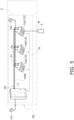
air conditioner 2, theoutdoor unit 11 is connected to acommercial power source 101 in order to supply power to theoutdoor unit 11. Power is supplied to eachindoor unit 12 from thecommercial power source 101 via theoutdoor unit 11 and a power source wiring PSW. In this way, in theair conditioner 2, thecommercial power source 101 for driving theoutdoor unit 11 and theindoor units 12 is the same system. As shown inFIG. 5 , the power source is not required to be the same system and may be thecommercial power source 101 for driving theoutdoor unit 11 and acommercial power source 102 for driving theindoor unit 12. Power is supplied to theaccessory device 3 from theindoor units 12 of theair conditioner 2. Theaccessory device 3 is electric equipment driven by power supplied from theair conditioner 2. - In the
air conditioner 2, theoutdoor unit 11, a firstindoor unit 12a, a secondindoor unit 12b, and a thirdindoor unit 12c form a refrigerant circuit RC, which together constitute the core of a single refrigerant system RS. Theoutdoor unit 11, the firstindoor unit 12a, the secondindoor unit 12b, and the thirdindoor unit 12c are connected by refrigerant pipes P1 and P2, and the same refrigerant circulates in theseoutdoor unit 11 andindoor units 12. Here, the refrigerant system RS includes not only theoutdoor unit 11, the firstindoor unit 12a, the secondindoor unit 12b, and the thirdindoor unit 12c but also theaccessory device 3 attached to theair conditioner 2. The refrigerant system RS may include a control device (not shown) that controls theair conditioner 2. Examples of the control device include a centralized controller that controls theoutdoor unit 11, the firstindoor unit 12a, the secondindoor unit 12b, and the thirdindoor unit 12c. - For example, in a case where there is another air conditioner other than the
air conditioner 2, when thesame accessory device 3 can be attached to both theair conditioner 2 and the other air conditioner, it is necessary to distinguish whether theaccessory device 3 is attached to theair conditioner 2 or the other air conditioner. The air conditioning system 1 performs system recognition to identify a system to which a target air conditioner belongs. This is achieved by distinguishing between a group related to the operation of theair conditioner 2 and a group related to the operation of other air conditioners, treating each group as a separate refrigerant system. Theaccessory device 3 is included in the refrigerant system RS to which the refrigerant circuit RC of theair conditioner 2 belongs. - The
outdoor unit 11 of theair conditioner 2 recognizes that theindoor units outdoor unit 11 can communicate with theindoor units air conditioner 2, theoutdoor unit 11 and theindoor units outdoor unit 11 and theindoor units air conditioner 2, theindoor unit 12 and theaccessory device 3 mutually transmit and receive data by communication, so that theindoor unit 12 and theaccessory device 3 can perform air conditioning related to the refrigerant system RS in cooperation with each other. - Here, a case will be described where the
indoor unit 12 of theair conditioner 2 supplies power to theaccessory device 3, and theindoor unit 12 and theaccessory device 3 perform current loop communication and high frequency communication by using a power supply wiring W. In the present disclosure, a frequency of a signal transmitted by high frequency communication is higher than a frequency of a signal transmitted by current loop communication. The power supply wiring W is a wiring different from the power source wiring PSW that supplies power from theoutdoor unit 11 to theindoor unit 12. However, the mode of supplying power from theair conditioner 2 to theaccessory device 3 is not limited to the case of supplying power from theindoor unit 12. For example, theoutdoor unit 11 may be configured to supply power to theaccessory device 3 by using a power supply wiring. In this configuration, theoutdoor unit 11 and theaccessory device 3 may perform the current loop communication and the high frequency communication by using a power supply wiring connecting theoutdoor unit 11 and theaccessory device 3. -
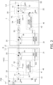
FIG. 2 shows a configuration related to communication between theair conditioner 2 and theaccessory device 3. Specifically,FIG. 2 shows a configuration related to communication between theindoor unit 12 of theair conditioner 2 and theaccessory device 3. - As shown in
FIG. 2 , theindoor unit 12 includes acurrent loop transmitter 21, afirst communication driver 31, afirst controller 41, aconstant voltage source 51, alow pass filter 52, andcapacitors indoor unit 12 includes aDC power source 60 connected to the power source wiring PSW and an internal power source line IL1. TheDC power source 60 is, for example, a rectifier circuit that generates a DC voltage from the power source wiring PSW. The internal power source line IL1 is a line that is connected to theDC power source 60 and supplies DC power to the inside of theindoor unit 12. - The
constant voltage source 51 obtains power from the internal power source line IL1 and generates a constant voltage. Theindoor unit 12 shown inFIG. 2 uses a Zener diode as theconstant voltage source 51. Although the Zener diode is used as theconstant voltage source 51 here, theconstant voltage source 51 may be configured by using an element or a circuit other than the Zener diode. A cathode of the Zener diode is connected to an output terminal OT of theconstant voltage source 51, and an anode of the Zener diode is connected to a ground GND. - The
current loop transmitter 21 is connected between the output terminal OT of theconstant voltage source 51 and a first line L1 of the power supply wiring W. Thecurrent loop transmitter 21 transmits a current signal CS by changing a state of connecting the output terminal OT of theconstant voltage source 51 and the first line L1. Thecurrent loop transmitter 21 transmits the current signal CS corresponding to a data signal DS1 provided from thefirst controller 41. Thecurrent loop transmitter 21 constitutes afirst communication device 20 together with acurrent loop receiver 22 to be described later. - The
current loop transmitter 21 can be constituted by, for example, a switching element. The switching element transmits the current signal CS by switching between a state in which the output terminal OT of theconstant voltage source 51 and the first line L1 are connected and a state in which the output terminal OT is not connected in accordance with the data signal DS 1. When the output terminal OT of theconstant voltage source 51 is connected to the first line L1, a current flows through the first line L1, and when the output terminal OT of theconstant voltage source 51 is not connected to the first line L1, a current does not flow through the first line L1. The digital current signal CS is generated by the state in which the current flows and the state in which the current does not flow (by turning on and off the current). The switching element includes, for example, a transistor. In the transistor used as the switching element, a collector (drain) is connected to the output terminal OT of theconstant voltage source 51, and an emitter (source) is connected to the first line L1. The data signal DS1 is provided from thefirst controller 41 to a base (gate) of the transistor. - The
low pass filter 52 is inserted into the first line L1 and a second line L2. Thelow pass filter 52 is a filter for removing high-frequency noise generated in the first line L1 and the second line L2. Thelow pass filter 52 can cut off a high frequency signal HF so that the high frequency signal HF provided to the first line L1 and the second line L2 by asecond communication device 30 is not transmitted to theconstant voltage source 51. - The
first communication driver 31 and thecapacitors second communication device 30. Asecond communication driver 32 andcapacitors second communication device 30. In other words, thesecond communication device 30 includes the first transceiver (thefirst communication driver 31 and thecapacitors 33 and 34) and the second transceiver (thesecond communication driver 32 and thecapacitors 35 and 36). Thefirst communication driver 31 and thecapacitors first communication driver 31 generates a voltage signal corresponding to a data signal DS3 provided from thefirst controller 41. Thecapacitors first communication driver 31 can transmit the high frequency signal HF through the power supply wiring W via thecapacitors - The
first communication driver 31 can receive the high frequency signal HF transmitted through the power supply wiring W via thecapacitors first communication driver 31 converts the received high frequency signal HF into the data signal DS3 and transmits the data signal DS3 to thefirst controller 41. - The
first controller 41 is implemented by a computer. Thefirst controller 41 includes, for example, a first control microcomputer. The first control microcomputer includes a microcontroller including a control calculator and a storage. A processor such as a CPU or a GPU can be used for the control calculator. The control calculator reads a program stored in the storage, and executes predetermined image processing and calculation processing in accordance with this program. Furthermore, the control calculator can write a calculation result to the storage and read information stored in the storage in accordance with the program. - As shown in
FIG. 2 , theaccessory device 3 includes thecurrent loop receiver 22, thesecond communication driver 32, asecond controller 42, alow pass filter 53, thecapacitors diode bridge 54, and aninternal power source 55. In addition, theaccessory device 3 includes an internal power source line IL2 for supplying power to the inside. - The
internal power source 55 obtains power from the power supply wiring W and generates a constant voltage for driving theaccessory device 3. Theinternal power source 55 includes, for example, a capacitor. When theinternal power source 55 is a capacitor, a voltage equal to or lower than a certain voltage generated at the output terminal OT of theconstant voltage source 51 is generated at one end of the capacitor. In other words, the capacitor constituting theinternal power source 55 accumulates charge supplied through the power supply wiring W until a difference between end-to-end voltages becomes a constant voltage. Although the capacitor is used as theinternal power source 55 here, theinternal power source 55 may be configured by using an element or a circuit other than the capacitor. One end (one end E1 of the internal power source 55) of the capacitor constituting theinternal power source 55 is connected to the internal power source line IL2, and the other end (the other end E2 of the internal power source 55) of the capacitor is connected to the ground. - The
current loop receiver 22 is connected between one end E1 of theinternal power source 55 and the first line L1 of the power supply wiring W. Thecurrent loop receiver 22 receives the current signal CS and converts the current signal CS into the data signal DS3. Thecurrent loop receiver 22 transmits the data signal DS3 corresponding to the current signal CS to thesecond controller 42. - The
current loop receiver 22 can be constituted by, for example, a photocoupler. An anode of a photodiode of the photocoupler is connected to the first line L1, and a cathode is connected to one end E1 of theinternal power source 55. In the case of the circuit shown inFIG. 2 , the cathode of the photodiode of the photocoupler is connected to one end of the capacitor. The photocoupler is used by being connected to, for example, an emitter load. In this case, an emitter of the photocoupler becomes a high voltage when the current signal CS is in an ON state (a state in which the current flows through the first line L1), and becomes a low voltage when the current signal CS is in an OFF state (a state in which the current does not flow through the first line L1). - The
low pass filter 53 is inserted into the first line L1 and the second line L2. Thelow pass filter 53 is a filter for removing high-frequency noise generated in the first line L1 and the second line L2. Thelow pass filter 53 can cut off a high frequency signal HF so that the high frequency signal HF provided to the first line L1 and the second line L2 by thesecond communication device 30 is not transmitted to thecurrent loop receiver 22 and theinternal power source 55. - The
diode bridge 54 is inserted between thelow pass filter 53 and thecurrent loop receiver 22. The power supply wiring W is configured such that a potential of the first line L1 is higher than a potential of the second line L2. Therefore, wiring according to the polarities of the first line L1 and the second line L2 of the power supply wiring W is required, such as connecting a high potential side of the power supply wiring W to thecurrent loop receiver 22 and connecting a low potential side of the power supply wiring W to the ground. However, an operator who installs theaccessory device 3 may not correctly recognize the polarities of the first line L1 and the second line L2. Therefore, thediode bridge 54 is configured such that one of two terminals on an output side of the diode bridge 54 (a terminal connected to the one end E1 of the internal power source 55) has a high potential and the other one (a terminal connected to the ground) has a low potential regardless of which of the two terminals on an input side of thediode bridge 54 the first line L1 and the second line L2 are connected to. Since thediode bridge 54 is provided, the power supply wiring W is a nonpolarized wiring. In other words, the operator can connect the power supply wiring W to theaccessory device 3 without considering the polarities of the first line L1 and the second line L2 of the power supply wiring W. - The
second communication driver 32 and thecapacitors second communication device 30. Thesecond communication driver 32 and thecapacitors second communication driver 32 generates a voltage signal corresponding to a data signal DS4 provided from thesecond controller 42. Thecapacitors second communication driver 32 can transmit the high frequency signal HF through the power supply wiring W via thecapacitors - The
second communication driver 32 can receive the high frequency signal HF transmitted through the power supply wiring W via thecapacitors second communication driver 32 converts the received high frequency signal HF into the data signal DS4 and transmits the data signal DS4 to thesecond controller 42. - The
second controller 42 is implemented by a computer. Thesecond controller 42 includes, for example, a second control microcomputer. The second control microcomputer includes a microcontroller including a control calculator and a storage. A processor such as a CPU or a GPU can be used for the control calculator. The control calculator reads a program stored in the storage, and executes predetermined image processing and calculation processing in accordance with this program. Furthermore, the control calculator can write a calculation result to the storage and read information stored in the storage in accordance with the program. - In the
air conditioner 2, for example, theoutdoor unit 11 includes a compressor (not shown), a first heat exchanger (not shown), and an expansion valve (not shown) constituting the refrigerant circuit RC, and theindoor unit 12 includes a second heat exchanger (not shown) constituting the refrigerant circuit RC. In theair conditioner 2 configured to perform a cooling operation, for example, the refrigerant passes through the compressor, the first heat exchanger, the expansion valve, and the second heat exchanger in the refrigerant circuit RC and returns to the compressor. The refrigerant circuit RC achieves a vapor compression refrigeration cycle. In this case, the refrigerant in a gas state is compressed by the compressor and discharged. In the first heat exchanger, the compressed high-temperature and high-pressure refrigerant exchanges heat with outdoor air to dissipate heat. At the expansion valve, the refrigerant having dissipated heat is decompressed and expanded. In the second heat exchanger of theindoor unit 12, the decompressed and expanded refrigerant exchanges heat with indoor air to absorb heat. At this time, cooling is performed by the indoor air cooled by heat exchange with the refrigerant. In the compressor, the refrigerant that has absorbed heat and gasified is compressed and discharged again to the first heat exchanger. - In the
air conditioner 2 configured to perform a heating operation, for example, the refrigerant passes through the compressor, the second heat exchanger, the expansion valve, and the first heat exchanger in the refrigerant circuit RC and returns to the compressor. The refrigerant circuit RC achieves a vapor compression refrigeration cycle. In this case, the refrigerant in a gas state is compressed by the compressor and discharged. In the second heat exchanger of theindoor unit 12, the compressed high-temperature and high-pressure refrigerant exchanges heat with the indoor air to dissipate heat. At this time, heating is performed by the indoor air heated by heat exchange with the refrigerant. At the expansion valve, the refrigerant having dissipated heat is decompressed and expanded. In the first heat exchanger, the decompressed and expanded refrigerant exchanges heat with outdoor air to absorb heat. In the compressor, the refrigerant that has absorbed heat and gasified is compressed and discharged again to the second heat exchanger. - The
air conditioner 2 may include a four-way valve that switches a circulation direction of the refrigerant in the refrigerant circuit RC so as to perform both the cooling operation and the heating operation. - An operation related to communication between the
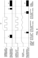
air conditioner 2 and theaccessory device 3 will be described with reference toFIGS. 3 and4 . In order to drive theaccessory device 3, the power source of theaccessory device 3 is turned on (step ST1). When the power source is turned on, a current flows through the power supply wiring W, and power is applied to theinternal power source 55 of theaccessory device 3. When theinternal power source 55 is a capacitor, charges are accumulated in the capacitor through the first line L1 and the second line L2. - When a sufficient time elapses until the
internal power source 55 can supply power to the inside of theaccessory device 3 after the power source of theaccessory device 3 is turned on, thefirst controller 41 outputs the data signal DS3 to thefirst communication driver 31 in order to cause thefirst communication driver 31 to transmit the high frequency signal HF for starting system recognition (step ST2). Thefirst communication driver 31 transmits the high frequency signal HF through thecapacitors indoor unit 12. - When the
first communication driver 31 communicates the high frequency signal HF, thesecond communication driver 32 and thesecond controller 42 are in an operable state by receiving power supplied from theinternal power source 55. Therefore, thesecond communication driver 32 receives the high frequency signal HF transmitted by thefirst communication driver 31, and transmits the data signal DS4 to thesecond controller 42. - The
second controller 42 receives the data signal DS4 to obtain information indicating that there has been a notification to start system recognition. Thesecond controller 42 which has obtained information that there has been a notification to start system recognition transmits the data signal DS4 to thesecond communication driver 32 in order to transmit, to thefirst controller 41, the high frequency signal HF for indicating that the start of system recognition has been accepted. Thesecond communication driver 32 which has received the data signal DS4 transmits the high frequency signal HF through thecapacitors accessory device 3. - The
first communication driver 31 which has received the high frequency signal HF transmitted by thesecond communication driver 32 transmits the data signal DS1 to thefirst controller 41. After transmitting the data signal DS3 for transmitting the high frequency signal HF to thefirst communication driver 31, thefirst controller 41 receives the data signal DS3 from thefirst communication driver 31 to learn that the system recognition is ready to start. - The
first controller 41 which has learned that the system recognition is ready to start performs system recognition by current loop communication (step ST3). Thefirst controller 41 transmits the data signal DS1 to thecurrent loop transmitter 21 and causes thecurrent loop transmitter 21 to transmit the current signal CS. Upon receiving the current signal CS, thecurrent loop receiver 22 of theaccessory device 3 transmits the data signal DS2 to thesecond controller 42. After causing thesecond communication driver 32 to transmit the high frequency signal HF, thesecond controller 42 receives the data signal D2 from thecurrent loop receiver 22, and learns that theindoor unit 12 is to recognize that theaccessory device 3 belongs to the same refrigerant system RS. Theaccessory device 3 which has learned that theaccessory device 3 belongs to the refrigerant system RS transmits the data signal DS4 to the second communication driver to cause thesecond communication driver 32 to transmit the high frequency signal HF in order to notify theindoor unit 12 that theaccessory device 3 belongs to the same refrigerant system RS. Thesecond controller 42 transmits the high frequency signal HF to notify thefirst controller 41 that the current signal CS for system recognition has been received. - Upon receiving the high frequency signal HF transmitted by the
second communication driver 32, thefirst communication driver 31 transmits, to thefirst controller 41, the data signal DS3 notifying reception of the high frequency signal HF. After causing thecurrent loop transmitter 21 to transmit the current signal CS, thefirst controller 41 learns that the high frequency signal HF has been received, to learn that theaccessory device 3 has received the current signal CS for system recognition. As described above, the current signal CS and the transmission and reception of the high frequency signal HF are transmitted and received through the power supply wiring W between theindoor unit 12 and theaccessory device 3, and thus, the recognition of the refrigerant system for confirming that theindoor unit 12 and theaccessory device 3 belong to the refrigerant system RS is completed (step ST15). - When the recognition of the refrigerant system is completed, normal data transfer by the high frequency signal HF via the power supply wiring W is started between the
indoor unit 12 and the accessory device 3 (step ST16). - As described above, the
controller 40 configures a communication network by sequentially causing thesecond communication device 30 to perform transmission and reception, thefirst communication device 20 to perform transmission and reception, and thesecond communication device 30 to perform transmission and reception between theair conditioner 2 and theaccessory device 3, thereby determining that theaccessory device 3 is connected. In other words, thecontroller 40 performs system recognition by sequentially performing transmission and reception by thesecond communication device 30, transmission and reception by thefirst communication device 20, and transmission and reception by thesecond communication device 30 between theair conditioner 2 and theaccessory device 3. Thecontroller 40 determines that theaccessory device 3 is connected to the refrigerant system RS on the basis of the system recognition. - The current loop communication of the
first communication device 20 shown inFIG. 4 is performed by turning on and off the current flowing through the power supply wiring W. In a case where theinternal power source 55 is a capacitor, when the current flowing through the power supply wiring W is turned off, the charge accumulated in the capacitor decreases, and the voltage decreases. Theaccessory device 3 is configured to operate even when the voltage of theinternal power source 55 is temporarily lowered by the current loop communication. As described above, communication is performed by turning on and off the current flowing through the power supply wiring W, so that thecurrent loop transmitter 21 can be constituted by the switching element, and the configuration of thecurrent loop transmitter 21 is simplified. - The frequency of the voltage signal (high frequency signal HF) used by the
second communication device 30 for communication is higher than the frequency of the current signal CS used by thefirst communication device 20 for current loop communication. Therefore, the air conditioning system 1 can perform communication in which crosstalk is less likely to occur by using the current signal CS of thefirst communication device 20 having a low frequency than by using thesecond communication device 30. In addition, by using the high frequency signal HF of thesecond communication device 30 higher than the frequency of the current signal CS of the current loop communication for data transfer, the air conditioning system 1 can transfer more data faster than when data is transferred by using thefirst communication device 20. - For example, if the
accessory device 3 is an outdoor temperature sensor, theaccessory device 3 can detect an outdoor air temperature, transmit a detection result from thesecond communication driver 32, and cause thefirst communication driver 31 of theindoor unit 12 to receive the detection result. In this case, the air conditioning system 1 can perform air conditioning by using the detection result of the outdoor air temperature detected by theaccessory device 3. For example, if theaccessory device 3 is a human detection sensor, theaccessory device 3 can detect the presence or absence of a human in an air conditioning target space, transmit a detection result from thesecond communication driver 32, and cause thefirst communication driver 31 of theindoor unit 12 to receive the detection result. In this case, the air conditioning system 1 can perform air conditioning by distinguishing a case where a person is present in the air conditioning target space from a case where a person is not present in the air conditioning target space by using the detection result of human detection by theaccessory device 3. For example, when theaccessory device 3 is a wireless receiver, an instruction from a user can be received wirelessly, the received instruction can be transmitted from thesecond communication driver 32, and thefirst communication driver 31 of theindoor unit 12 can receive the instruction. In this case, the air conditioning system 1 can perform air conditioning by using communication data of wireless communication by theaccessory device 3. For example, whenaccessory device 3 is a display device, data required for display can be transmitted from thefirst communication driver 31 and received by thesecond communication driver 32. In this case, the air conditioning system 1 can cause theaccessory device 3 to display data related to air conditioning transmitted to theaccessory device 3. - In the above embodiment, a case has been described where the air conditioning system 1 includes one refrigerant system RS, and one refrigerant system RS includes only a plurality of
indoor units 12. However, the mode of the air conditioning system 1 is not limited to the above-described mode. For example, the air conditioning system 1 may include a plurality of refrigerant systems, and each of the refrigerant systems may include an outdoor unit and an indoor unit. The air conditioning system 1 may be configured such that one refrigerant system includes a plurality of outdoor units. - In the above embodiment, a case has been described where one
accessory device 3 is connected to theair conditioner 2 of one refrigerant system RS. However, a plurality of theaccessory devices 3 may be connected to theair conditioner 2 of one refrigerant system RS. For example, theaccessory device 3 may be connected to each of theindoor units accessory devices 3 may be connected to the air conditioning system 1. - In the air conditioning system 1, a case has been described where the
indoor unit 12 and theaccessory device 3 communicate with each other. However, the configuration in which theaccessory device 3 communicates in the same refrigerant system is not limited to the configuration in which theaccessory device 3 communicates only with theindoor unit 12. For example, theoutdoor unit 11 and theaccessory device 3, or theoutdoor unit 11, theindoor unit 12, and theaccessory device 3 may be communicable with each other via theindoor unit 12. When a plurality ofaccessory devices 3 is included in one refrigerant system, theaccessory devices 3 may be indirectly communicable with each other through theindoor unit 12. - The power for driving the
indoor unit 12 may be supplied from other than theoutdoor unit 11. For example, as shown inFIG. 5 , the power for driving theindoor unit 12 may be supplied from thecommercial power source 102 different from thecommercial power source 101. - In the air conditioning system 1, the communication performed between the
outdoor unit 11 and theindoor unit 12 in one refrigerant system RS is not limited to communication performed through the power source wiring PSW. For example, as shown inFIG. 5 , theoutdoor unit 11 and theindoor unit 12 may be communicable with each other by using a communication wiring CL other than the power source wiring PSW. The communication using the communication wiring CL is, for example, communication by a voltage signal. The communication performed by the communication wiring CL may also be configured to selectively use two types of signals, a low frequency signal and a high frequency signal. When theaccessory device 3 and theindoor unit 12 are connected by the power supply wiring W, theoutdoor unit 11 belonging to the same refrigerant system RS and theaccessory device 3 may be also configured to indirectly communicate with each other via theindoor unit 12 by using the communication wiring CL. When theaccessory device 3 and theoutdoor unit 11 are connected by the power supply wiring, theoutdoor unit 11 belonging to the same refrigerant system RS and theaccessory device 3 may be also configured to indirectly communicate with each other via theindoor unit 12 by using the communication wiring CL. - In the above embodiment, a case has been described where transmission and reception by the current loop communication can be performed by using the
current loop transmitter 21 and thecurrent loop receiver 22 constituting thefirst communication device 20. However, a current loop transceiver capable of transmission and reception may be used instead of thecurrent loop receiver 22 of theindoor unit 12, and a current loop transceiver capable of transmission and reception may be used instead of thecurrent loop transmitter 21 of theindoor unit 12. - (7-1)
The air conditioning system 1 according to the above embodiment includes theair conditioner 2 and theaccessory device 3 driven by power supplied from theair conditioner 2. In the air conditioning system 1, thecontroller 40 uses the current loop communication of thefirst communication device 20 for recognition of theaccessory device 3, and uses the voltage signal (high frequency signal HF) of thesecond communication device 30 for data communication. Both the current loop communication (communication using the current signal CS) and the communication using the voltage signal (high frequency signal HF) are performed by using the power supply wiring W. The power supply wiring W is a wire that supplies power from theair conditioner 2 to theaccessory device 3. In such an air conditioning system 1, as compared with a case where device recognition and data communication are performed only by the current loop communication, the components of theaccessory device 3 can be easily downsized, and theaccessory device 3 can be easily downsized. In addition, by using thesecond communication device 30, downsizing is facilitated, and data transfer time can be shortened. - (7-2)
In the current loop communication of thefirst communication device 20, communication is performed by thecurrent loop transmitter 21 turning on and off the current flowing through the power supply wiring W. In such a configuration, for example, a switching element can be used for thecurrent loop transmitter 21. In a case where the switching element is used for thecurrent loop transmitter 21, the configuration of thecurrent loop transmitter 21 can be simplified by using a transistor as the switching element. - (7-3)
The frequency of the high frequency signal HF used by thesecond communication device 30 for communication is higher than the frequency of the current signal CS used by thefirst communication device 20 for current loop communication. The air conditioning system 1 can perform communication in which crosstalk is less likely to occur by using the current signal CS of thefirst communication device 20 having a low frequency than by using thesecond communication device 30. By using thefirst communication device 20 for system recognition, the air conditioning system 1 can maintain high reliability of the system recognition. On the other hand, by using thesecond communication device 30 using the high frequency signal HF having a frequency higher than the frequency of the current signal CS of the current loop communication for data transfer, the air conditioning system 1 can transfer more data faster than when data is transferred by using thefirst communication device 20. - (7-4)
In the air conditioning system 1 according to the above embodiment, thecontroller 40 configures a communication network by determining the connection of theaccessory device 3 using the current loop communication. The air conditioning system 1 performs data communication using a voltage signal after configuring the communication network. As a result, the air conditioning system 1 can reliably utilize the communication of theaccessory device 3 for the operation of the refrigerant system RS. - (7-5)
Thecontroller 40 sequentially causes thesecond communication device 30 to perform transmission and reception, thefirst communication device 20 to perform transmission and reception, and thesecond communication device 30 to perform transmission and reception between theair conditioner 2 and theaccessory device 3, and determines that theaccessory device 3 is connected. During the configuration of the communication network, the transmission and reception of voltage signals occur before and after the current loop communication. Therefore, compared to the case where only one of either current loop communication or voltage signal communication is conducted, the determination of the connection of theaccessory device 3 can be reliably performed in a shorter time. - (7-6)
The power supply wiring W of the air conditioning system 1 according to the above embodiment is a nonpolarized wiring. Therefore, since it is not necessary to specify the polarity when the power supply wiring W is connected to theaccessory device 3 on site, the power supply wiring W can be smoothly connected. - The embodiments of the present disclosure have been described above. It will be understood that various changes to modes and details can be made without departing from the gist and scope of the present disclosure recited in the claims.
-
- 1: air conditioning system
- 2: air conditioner
- 3: accessory device
- 20: first communication device
- 30: second communication device
- 40: controller
- W: power supply wiring
- Patent Literature 1:
JP 2020-167578 A
Claims (6)
- An air conditioning system (1) comprising:an air conditioner (2);an accessory device (3) driven by power supplied from the air conditioner;a power supply wiring (W) that supplies power from the air conditioner to the accessory device;a first communication device (20) that changes a current flowing through the power supply wiring and performs current loop communication between the air conditioner and the accessory device;a second communication device (30) that superimposes a voltage signal on the power supply wiring and performs communication between the air conditioner and the accessory device; anda controller (40) that controls the first communication device and the second communication device.
- The air conditioning system (1) according to claim 1, wherein the current loop communication of the first communication device is performed by turning on and off the current flowing through the power supply wiring.
- The air conditioning system (1) according to claim 1 or 2, wherein a frequency of the voltage signal of the second communication device is higher than a frequency of the current loop communication of the first communication device.
- The air conditioning system (1) according to any one of claims 1 to 3, wherein the controller configures a communication network by determining, using the current loop communication, that the accessory device is connected, and performs data communication by the voltage signal after the configuration of the communication network.
- The air conditioning system (1) according to claim 4, wherein, by sequentially causing the second communication device to perform transmission and reception, the first communication device to perform transmission and reception, and the second communication device to perform transmission and reception between the air conditioner and the accessory device, the controller determines that the accessory device is connected, and configures the communication network.
- The air conditioning system (1) according to any one of claims 1 to 5, wherein the power supply wiring is a nonpolarized wiring.
Applications Claiming Priority (2)
| Application Number | Priority Date | Filing Date | Title |
|---|---|---|---|
| JP2022023020A JP2023119898A (en) | 2022-02-17 | 2022-02-17 | air conditioning system |
| PCT/JP2023/004702 WO2023157787A1 (en) | 2022-02-17 | 2023-02-13 | Air-conditioning system |
Publications (2)
| Publication Number | Publication Date |
|---|---|
| EP4481291A1 true EP4481291A1 (en) | 2024-12-25 |
| EP4481291A4 EP4481291A4 (en) | 2025-05-28 |
Family
ID=87578215
Family Applications (1)
| Application Number | Title | Priority Date | Filing Date |
|---|---|---|---|
| EP23756312.7A Pending EP4481291A4 (en) | 2022-02-17 | 2023-02-13 | AIR CONDITIONING |
Country Status (5)
| Country | Link |
|---|---|
| US (1) | US20240401839A1 (en) |
| EP (1) | EP4481291A4 (en) |
| JP (1) | JP2023119898A (en) |
| CN (1) | CN118679352A (en) |
| WO (1) | WO2023157787A1 (en) |
Family Cites Families (8)
| Publication number | Priority date | Publication date | Assignee | Title |
|---|---|---|---|---|
| JP2004134928A (en) * | 2002-10-09 | 2004-04-30 | Mitsubishi Heavy Ind Ltd | Signal transmission equipment |
| JP2012016253A (en) * | 2010-07-05 | 2012-01-19 | Panasonic Electric Works Co Ltd | Energy management system |
| KR101587066B1 (en) * | 2010-08-05 | 2016-01-21 | 삼성전자 주식회사 | Air conditioner and communication method thereof |
| JP2016008734A (en) * | 2014-06-23 | 2016-01-18 | ダイキン工業株式会社 | Air conditioning system |
| JP6425798B2 (en) * | 2015-04-01 | 2018-11-21 | 三菱電機株式会社 | Communication system and communication device |
| CN106440052B (en) * | 2016-11-03 | 2022-03-15 | 广东美的制冷设备有限公司 | Air conditioner and control method thereof |
| CN110710121B (en) * | 2017-06-16 | 2021-07-23 | 三菱电机株式会社 | Communication device, communication method, and recording medium |
| JP6844644B2 (en) | 2019-03-29 | 2021-03-17 | ダイキン工業株式会社 | Equipment network system |
-
2022
- 2022-02-17 JP JP2022023020A patent/JP2023119898A/en active Pending
-
2023
- 2023-02-13 CN CN202380021221.4A patent/CN118679352A/en active Pending
- 2023-02-13 EP EP23756312.7A patent/EP4481291A4/en active Pending
- 2023-02-13 WO PCT/JP2023/004702 patent/WO2023157787A1/en not_active Ceased
-
2024
- 2024-08-13 US US18/802,003 patent/US20240401839A1/en active Pending
Also Published As
| Publication number | Publication date |
|---|---|
| WO2023157787A1 (en) | 2023-08-24 |
| US20240401839A1 (en) | 2024-12-05 |
| CN118679352A (en) | 2024-09-20 |
| EP4481291A4 (en) | 2025-05-28 |
| JP2023119898A (en) | 2023-08-29 |
Similar Documents
| Publication | Publication Date | Title |
|---|---|---|
| US9217578B2 (en) | Power device and safety control method thereof | |
| CN110207342B (en) | Indoor unit, control circuit and control method of air conditioning unit and readable storage medium | |
| KR100974850B1 (en) | Air conditioner and indoor unit | |
| KR101134914B1 (en) | Air conditioning apparatus and outdoor unit | |
| JP2011211870A (en) | Power supply apparatus | |
| KR100973683B1 (en) | Communication control method of air conditioner, air conditioner and outdoor unit | |
| US20240102688A1 (en) | Indoor unit | |
| CN113300738B (en) | Cross-phase communicator, communication method, system and storage medium | |
| US8788102B2 (en) | Air conditioner | |
| US20240401840A1 (en) | Air conditioner | |
| KR20140097693A (en) | Communication module, multi-type air conditioning apparatus using the same, and control method thereof | |
| US20240401839A1 (en) | Air conditioning system | |
| US10396603B2 (en) | Power receiving apparatus that wirelessly receives power, control method of the same, and storage medium | |
| US20250102181A1 (en) | Air conditioning-related equipment and air conditioning system | |
| CN115076938B (en) | Indoor and outdoor unit communication circuit, air conditioner and communication control method of air conditioner | |
| JP2022185182A (en) | System component | |
| KR101586296B1 (en) | Multi-type air conditioner and its communication method | |
| CN114076401B (en) | Communication circuit, electronic equipment and communication method | |
| CN112154079B (en) | Method of pairing an electric vehicle and a power terminal in a power station for an electric vehicle | |
| US20090093909A1 (en) | Control system and a method for controlling a refrigeration system comprising two or more compressors | |
| JP2002061921A (en) | Power supply system and power supply method | |
| CN216307973U (en) | Air conditioner | |
| KR100187288B1 (en) | Data Transceiver of Multi Type Air Conditioner | |
| CN117537454A (en) | Communication mode determining method of air conditioner, controller, air conditioner and storage medium | |
| CN117346290A (en) | Communication circuits, electronic equipment and communication methods |
Legal Events
| Date | Code | Title | Description |
|---|---|---|---|
| STAA | Information on the status of an ep patent application or granted ep patent |
Free format text: STATUS: THE INTERNATIONAL PUBLICATION HAS BEEN MADE |
|
| PUAI | Public reference made under article 153(3) epc to a published international application that has entered the european phase |
Free format text: ORIGINAL CODE: 0009012 |
|
| STAA | Information on the status of an ep patent application or granted ep patent |
Free format text: STATUS: REQUEST FOR EXAMINATION WAS MADE |
|
| 17P | Request for examination filed |
Effective date: 20240905 |
|
| AK | Designated contracting states |
Kind code of ref document: A1 Designated state(s): AL AT BE BG CH CY CZ DE DK EE ES FI FR GB GR HR HU IE IS IT LI LT LU LV MC ME MK MT NL NO PL PT RO RS SE SI SK SM TR |
|
| DAV | Request for validation of the european patent (deleted) | ||
| DAX | Request for extension of the european patent (deleted) | ||
| A4 | Supplementary search report drawn up and despatched |
Effective date: 20250428 |
|
| RIC1 | Information provided on ipc code assigned before grant |
Ipc: F24F 11/89 20180101ALI20250422BHEP Ipc: F24F 11/54 20180101ALI20250422BHEP Ipc: F24F 11/63 20180101ALI20250422BHEP Ipc: F24F 11/56 20180101ALI20250422BHEP Ipc: F24F 11/50 20180101ALI20250422BHEP Ipc: H04B 3/54 20060101ALI20250422BHEP Ipc: F24F 11/88 20180101AFI20250422BHEP |
|
| P01 | Opt-out of the competence of the unified patent court (upc) registered |
Free format text: CASE NUMBER: UPC_APP_3800_4481291/2025 Effective date: 20250820 |
|
| GRAP | Despatch of communication of intention to grant a patent |
Free format text: ORIGINAL CODE: EPIDOSNIGR1 |
|
| STAA | Information on the status of an ep patent application or granted ep patent |
Free format text: STATUS: GRANT OF PATENT IS INTENDED |
|
| RIC1 | Information provided on ipc code assigned before grant |
Ipc: F24F 11/88 20180101AFI20260127BHEP Ipc: F24F 11/89 20180101ALI20260127BHEP Ipc: F24F 11/54 20180101ALI20260127BHEP Ipc: F24F 11/63 20180101ALI20260127BHEP Ipc: F24F 11/56 20180101ALI20260127BHEP Ipc: F24F 11/50 20180101ALI20260127BHEP Ipc: H04B 3/54 20060101ALI20260127BHEP Ipc: F24F 11/58 20180101ALI20260127BHEP |
|
| INTG | Intention to grant announced |
Effective date: 20260209 |
|
| GRAS | Grant fee paid |
Free format text: ORIGINAL CODE: EPIDOSNIGR3 |
|
| GRAA | (expected) grant |
Free format text: ORIGINAL CODE: 0009210 |
|
| STAA | Information on the status of an ep patent application or granted ep patent |
Free format text: STATUS: THE PATENT HAS BEEN GRANTED |