EP4481289A1 - Air conditioner, air conditioning system, and determination method - Google Patents
Air conditioner, air conditioning system, and determination method Download PDFInfo
- Publication number
- EP4481289A1 EP4481289A1 EP23791827.1A EP23791827A EP4481289A1 EP 4481289 A1 EP4481289 A1 EP 4481289A1 EP 23791827 A EP23791827 A EP 23791827A EP 4481289 A1 EP4481289 A1 EP 4481289A1
- Authority
- EP
- European Patent Office
- Prior art keywords
- shutoff valve
- piping
- refrigerant
- temperature sensor
- temperature
- Prior art date
- Legal status (The legal status is an assumption and is not a legal conclusion. Google has not performed a legal analysis and makes no representation as to the accuracy of the status listed.)
- Pending
Links
Images


Classifications
-
- F—MECHANICAL ENGINEERING; LIGHTING; HEATING; WEAPONS; BLASTING
- F25—REFRIGERATION OR COOLING; COMBINED HEATING AND REFRIGERATION SYSTEMS; HEAT PUMP SYSTEMS; MANUFACTURE OR STORAGE OF ICE; LIQUEFACTION SOLIDIFICATION OF GASES
- F25B—REFRIGERATION MACHINES, PLANTS OR SYSTEMS; COMBINED HEATING AND REFRIGERATION SYSTEMS; HEAT PUMP SYSTEMS
- F25B49/00—Arrangement or mounting of control or safety devices
- F25B49/02—Arrangement or mounting of control or safety devices for compression type machines, plants or systems
-
- F—MECHANICAL ENGINEERING; LIGHTING; HEATING; WEAPONS; BLASTING
- F25—REFRIGERATION OR COOLING; COMBINED HEATING AND REFRIGERATION SYSTEMS; HEAT PUMP SYSTEMS; MANUFACTURE OR STORAGE OF ICE; LIQUEFACTION SOLIDIFICATION OF GASES
- F25B—REFRIGERATION MACHINES, PLANTS OR SYSTEMS; COMBINED HEATING AND REFRIGERATION SYSTEMS; HEAT PUMP SYSTEMS
- F25B49/00—Arrangement or mounting of control or safety devices
- F25B49/005—Arrangement or mounting of control or safety devices of safety devices
-
- F—MECHANICAL ENGINEERING; LIGHTING; HEATING; WEAPONS; BLASTING
- F24—HEATING; RANGES; VENTILATING
- F24F—AIR-CONDITIONING; AIR-HUMIDIFICATION; VENTILATION; USE OF AIR CURRENTS FOR SCREENING
- F24F11/00—Control or safety arrangements
- F24F11/30—Control or safety arrangements for purposes related to the operation of the system, e.g. for safety or monitoring
- F24F11/32—Responding to malfunctions or emergencies
- F24F11/36—Responding to malfunctions or emergencies to leakage of heat-exchange fluid
-
- F—MECHANICAL ENGINEERING; LIGHTING; HEATING; WEAPONS; BLASTING
- F25—REFRIGERATION OR COOLING; COMBINED HEATING AND REFRIGERATION SYSTEMS; HEAT PUMP SYSTEMS; MANUFACTURE OR STORAGE OF ICE; LIQUEFACTION SOLIDIFICATION OF GASES
- F25B—REFRIGERATION MACHINES, PLANTS OR SYSTEMS; COMBINED HEATING AND REFRIGERATION SYSTEMS; HEAT PUMP SYSTEMS
- F25B13/00—Compression machines, plants or systems, with reversible cycle
-
- F—MECHANICAL ENGINEERING; LIGHTING; HEATING; WEAPONS; BLASTING
- F25—REFRIGERATION OR COOLING; COMBINED HEATING AND REFRIGERATION SYSTEMS; HEAT PUMP SYSTEMS; MANUFACTURE OR STORAGE OF ICE; LIQUEFACTION SOLIDIFICATION OF GASES
- F25B—REFRIGERATION MACHINES, PLANTS OR SYSTEMS; COMBINED HEATING AND REFRIGERATION SYSTEMS; HEAT PUMP SYSTEMS
- F25B2313/00—Compression machines, plants or systems with reversible cycle not otherwise provided for
- F25B2313/023—Compression machines, plants or systems with reversible cycle not otherwise provided for using multiple indoor units
- F25B2313/0233—Compression machines, plants or systems with reversible cycle not otherwise provided for using multiple indoor units in parallel arrangements
-
- F—MECHANICAL ENGINEERING; LIGHTING; HEATING; WEAPONS; BLASTING
- F25—REFRIGERATION OR COOLING; COMBINED HEATING AND REFRIGERATION SYSTEMS; HEAT PUMP SYSTEMS; MANUFACTURE OR STORAGE OF ICE; LIQUEFACTION SOLIDIFICATION OF GASES
- F25B—REFRIGERATION MACHINES, PLANTS OR SYSTEMS; COMBINED HEATING AND REFRIGERATION SYSTEMS; HEAT PUMP SYSTEMS
- F25B2313/00—Compression machines, plants or systems with reversible cycle not otherwise provided for
- F25B2313/031—Sensor arrangements
- F25B2313/0314—Temperature sensors near the indoor heat exchanger
-
- F—MECHANICAL ENGINEERING; LIGHTING; HEATING; WEAPONS; BLASTING
- F25—REFRIGERATION OR COOLING; COMBINED HEATING AND REFRIGERATION SYSTEMS; HEAT PUMP SYSTEMS; MANUFACTURE OR STORAGE OF ICE; LIQUEFACTION SOLIDIFICATION OF GASES
- F25B—REFRIGERATION MACHINES, PLANTS OR SYSTEMS; COMBINED HEATING AND REFRIGERATION SYSTEMS; HEAT PUMP SYSTEMS
- F25B2500/00—Problems to be solved
- F25B2500/22—Preventing, detecting or repairing leaks of refrigeration fluids
- F25B2500/222—Detecting refrigerant leaks
-
- F—MECHANICAL ENGINEERING; LIGHTING; HEATING; WEAPONS; BLASTING
- F25—REFRIGERATION OR COOLING; COMBINED HEATING AND REFRIGERATION SYSTEMS; HEAT PUMP SYSTEMS; MANUFACTURE OR STORAGE OF ICE; LIQUEFACTION SOLIDIFICATION OF GASES
- F25B—REFRIGERATION MACHINES, PLANTS OR SYSTEMS; COMBINED HEATING AND REFRIGERATION SYSTEMS; HEAT PUMP SYSTEMS
- F25B2600/00—Control issues
- F25B2600/25—Control of valves
- F25B2600/2519—On-off valves
Definitions
- the present disclosure relates to an air conditioner, an air conditioning system, and a determination method.
- the air conditioner may include a shutoff valve that shuts off circulation of a refrigerant in a case where a refrigerant leakage is detected in order to reduce a leakage amount.
- a shutoff valve inspection process of determining whether or not the shutoff valve is normally open or closed is performed in regular inspection or the like (for example, refer to PTL 1 and PTL 2).
- PTL 1 discloses a system that determines whether or not the shutoff valve is correctly open or closed, based on how much the temperature of the refrigerant measured inside the indoor unit has changed before and after the shutoff valve is closed.
- the size of the indoor heat exchanger changes according to the characteristics (type, capacity, and the like) of the indoor unit of the air conditioner. Therefore, a temperature change amount after the shutoff valve is closed and the time required for the temperature change are not constant. For this reason, in a system in which the temperature measured before and after the shutoff valve is closed is compared as in the related art, there is a possibility that the accuracy of determining whether or not the shutoff valve is open or closed may be reduced.
- the temperature of the refrigerant changes.
- the temperature value used for the opening and closing determination of the shutoff valve is not measured at the same time, and when the operation point at the time of temperature measurement after the shutoff valve is closed is changed from the operation point at the time of temperature measurement before the shutoff valve is closed, it is difficult to correctly determine whether or not the change in temperature is due to the opening and closing of the shutoff valve, and there is a possibility that the determination accuracy may be lowered.
- Target of the present disclosure is to provide an air conditioner, an air conditioning system, and a determination method capable of accurately determining whether or not a shutoff valve is open or closed.
- an air conditioner includes an outdoor unit; an indoor unit; a refrigerant piping that circulates a refrigerant between the outdoor unit and the indoor unit; a shutoff valve that is provided to the refrigerant piping and is capable of shutting off the circulation of the refrigerant; an upstream temperature sensor that is provided in the refrigerant piping on an upstream side of the shutoff valve and measures an upstream temperature representing a temperature of the refrigerant on the upstream side of the shutoff valve; a downstream temperature sensor that is provided in the refrigerant piping on a downstream side of the shutoff valve and measures a downstream temperature representing a temperature of the refrigerant on the downstream side of the shutoff valve; and a determination unit that determines whether or not the shutoff valve is open or closed based on the upstream temperature and the downstream temperature measured at the same time.
- an air conditioning system includes an outdoor unit; a plurality of indoor units; a refrigerant piping that circulates a refrigerant between the outdoor unit and each of the plurality of indoor units, and includes a main piping that is a piping on an outdoor unit side and a plurality of branch pipings that branch from a branching point of the main piping to each of the plurality of indoor units; a plurality of shutoff valves that are provided in each of the plurality of branch pipings and are capable of individually shutting off circulation of the refrigerant in the branch piping; an upstream temperature sensor that is provided on an upstream side of the shutoff valve in each of the plurality of branch pipings, and measures an upstream temperature representing a temperature of the refrigerant on the upstream side of the shutoff valve; a downstream temperature sensor that is provided on a downstream side of the shutoff valve in each of the plurality of branch pipings, and measures a downstream temperature representing a temperature of the refrigerant
- a determination method of determining whether or not a shutoff valve of an air conditioner including an outdoor unit, an indoor unit, a refrigerant piping that circulates a refrigerant between the outdoor unit and the indoor unit, a shutoff valve that is provided to the refrigerant piping and is capable of shutting off the circulation of the refrigerant, an upstream temperature sensor that is provided in the refrigerant piping on an upstream side of the shutoff valve, and a downstream temperature sensor that is provided in the refrigerant piping on a downstream side of the shutoff valve is open or closed
- the determination method including: a step of measuring, via the upstream temperature sensor, an upstream temperature representing a temperature of the refrigerant on the upstream side of the shutoff valve; a step of measuring, via the downstream temperature sensor, a downstream temperature representing a temperature of the refrigerant on the downstream side of the shutoff valve; and a step of determining whether or not the shutoff valve is operated, based on the up
- Fig. 1 is a diagram showing an overall configuration of an air conditioner according to a first embodiment.
- an air conditioner 100 includes an outdoor unit 1, an indoor unit 2, a refrigerant piping 3, and a shutoff valve device 4.
- the outdoor unit 1 includes a compressor 10, a four-way valve 11, an outdoor heat exchanger 12, and a receiver 13.
- the compressor 10 compresses a refrigerant R to generate high-temperature and high-pressure gas (gas refrigerant).
- the four-way valve 11 switches the circulation direction of the refrigerant R in the refrigerant piping 3 according to an operation mode of the air conditioner 100.
- the air conditioner 100 can be switched to two operation modes of a cooling operation mode and a heating operation mode.
- Fig. 1 shows an example of the cooling operation mode.
- the four-way valve 11 sets the destination of the refrigerant R discharged from the compressor 10 to the outdoor heat exchanger 12.
- the four-way valve 11 makes the indoor unit 2 (indoor heat exchanger 20) a destination of the refrigerant R discharged from the compressor 10.
- the receiver 13 temporarily stores the introduced refrigerant R (liquid refrigerant).
- the indoor unit 2 includes an indoor heat exchanger 20 and an expansion valve 21.
- the indoor heat exchanger 20 exchanges heat between the refrigerant R supplied to the inside and the indoor air.
- the indoor heat exchanger 20 functions as an evaporator in a cooling operation mode (mode shown in Fig. 1 ) and functions as a condenser in a heating operation mode.
- the expansion valve 21 decompresses the refrigerant R, which is made high pressure by the compressor 10 of the outdoor unit 1.
- the first indoor temperature sensor 22 and the second indoor temperature sensor 23 that measure the temperature of the refrigerant R flowing into the indoor heat exchanger 20 and the temperature of the refrigerant R flowing out from the indoor heat exchanger 20 are provided in the vicinity of the inlet and the outlet of the refrigerant piping 3 (33, 34) passing through the indoor heat exchanger 20.
- the first indoor temperature sensor 22 and the second indoor temperature sensor 23 may be existing temperature sensors provided in the indoor unit 2.
- the liquid-side crossover piping 352 through which the refrigerant R is sent from the outdoor unit 1 is an outbound crossover piping
- the gas-side crossover piping 351 through which the refrigerant R returns to the outdoor unit 1 is a return crossover piping.
- the gas-side crossover piping 351 through which the refrigerant R is sent from the outdoor unit 1 is the outbound crossover piping
- the liquid-side crossover piping 352 through which the refrigerant R returns to the outdoor unit 1 is the return crossover piping.
- the shutoff valve device 4 is provided in a crossover piping 35 between the outdoor unit 1 and the indoor unit 2.
- the shutoff valve device 4 includes a gas-side shutoff valve 40, a liquid-side shutoff valve 41, and a CPU 42 (determination unit).
- the gas-side shutoff valve 40 is open or closed according to the control of the CPU 42 to permit or shut off the circulation of the refrigerant R in the gas-side crossover piping 351.
- the liquid-side shutoff valve 41 is open or closed according to the control of the CPU 42 to permit or shut off the circulation of the refrigerant R in the liquid-side crossover piping 352.
- the CPU 42 outputs a control signal for instructing the opening and closing of the gas-side shutoff valve 40 and the liquid-side shutoff valve 41.
- the CPU 42 according to the present embodiment functions as a determination unit that determines whether or not the gas-side shutoff valve 40 and the liquid-side shutoff valve 41 are open or closed when the shutoff valve is inspected.
- Fig. 2 is a flowchart showing an example of the processing of the air conditioner according to the first embodiment.
- a case where an opening and closing operation of the gas-side shutoff valve 40 is inspected will be described with reference to Fig. 2 .
- the air conditioner 100 is in operation in a cooling operation mode shown in Fig. 1 with the outdoor unit 1 and the indoor unit 2.
- the CPU 42 of the shutoff valve device 4 determines whether or not a closing operation of the gas-side shutoff valve 40 is normally performed.
- the CPU 42 outputs a close command (control signal) to the gas-side shutoff valve 40 (step S10).
- the CPU 42 acquires the temperature of the refrigerant R on the upstream side (upstream temperature) of the gas-side shutoff valve 40 and the temperature of the refrigerant R on the downstream side (downstream temperature) (step S11). At this time, the CPU 42 may acquire the upstream temperature and the downstream temperature after an elapse of a predetermined time from when the close command is output.
- the gas-side indoor unit piping 33, the gas-side crossover piping 351, and the gas-side outdoor unit piping 31 function as a return route of the refrigerant R.
- the gas-side indoor unit piping 33 and the gas-side crossover piping 351 closer to the indoor unit 2 side with respect to the gas-side shutoff valve 40 are on the upstream side.
- the gas-side outdoor unit piping 31 and the gas-side crossover piping 351 closer to the outdoor unit 1 side with respect to the gas-side shutoff valve 40 are on the downstream side.
- the CPU 42 acquires the upstream temperature from the first indoor temperature sensor 22 of the indoor unit 2 and acquires the downstream temperature from the first outdoor temperature sensor 14 of the outdoor unit 1. The upstream temperature and the downstream temperature are measured by each temperature sensor at the same time.
- the CPU 42 determines whether or not the closing operation of the gas-side shutoff valve 40 is normally performed, based on the upstream temperature and the downstream temperature (step S12).
- the pressure on the upstream side of the shutoff valve is higher than the pressure on the downstream side.
- the temperature of the refrigerant is higher on the upstream side than on the downstream side of the shutoff valve. Therefore, the CPU 42 determines whether or not the upstream temperature is higher than the downstream temperature by a predetermined first temperature difference or more after the close command is output to the gas-side shutoff valve 40.
- step S12 determines that the closing operation of the gas-side shutoff valve 40 is normally performed (step S13).
- step S12 NO
- the CPU 42 determines that the closing operation of the gas-side shutoff valve 40 is not normally performed (step S14).
- the CPU 42 of the shutoff valve device 4 determines whether or not an opening operation of the gas-side shutoff valve 40 is normally performed.
- the CPU 42 outputs an open command (control signal) to the gas-side shutoff valve 40 (step S15).
- the CPU 42 acquires the upstream temperature from the first indoor temperature sensor 22 of the indoor unit 2 and acquires the downstream temperature from the first outdoor temperature sensor 14 of the outdoor unit 1 (step S 16). At this time, the CPU 42 may acquire the upstream temperature and the downstream temperature after an elapse of a predetermined time from when the open command is output. The upstream temperature and the downstream temperature are measured by each temperature sensor at the same time.
- the CPU 42 determines whether or not the opening operation of the gas-side shutoff valve 40 is normally performed, based on the upstream temperature and the downstream temperature (step S17). In a case where the shutoff valve is opened during driving, the pressure on the upstream side and the downstream side of the shutoff valve substantially coincide with each other, and the temperatures also substantially coincide with each other. Therefore, the CPU 42 determines whether or not the temperature difference between the upstream temperature and the downstream temperature is smaller than a predetermined second temperature difference after the open command is output to the gas-side shutoff valve 40.
- step S17 In a case where the temperature difference between the upstream temperature and the downstream temperature is less than the second temperature difference (step S17; YES), the CPU 42 determines that the opening operation of the gas-side shutoff valve 40 is normally performed (step S18).
- step S17 NO
- the CPU 42 determines that the opening operation of the gas-side shutoff valve 40 is not normally performed (step S19).
- the CPU 42 performs the same process for the liquid-side shutoff valve 41 and inspects the opening and closing operation after inspecting the opening and closing operation of the gas-side shutoff valve 40.
- the liquid-side outdoor unit piping 32 and the liquid-side crossover piping 352 on the outdoor unit 1 side with respect to the liquid-side shutoff valve 41 are on the upstream side.
- the liquid-side indoor unit piping 34 and the liquid-side crossover piping 352 on the indoor unit 2 side with respect to the liquid-side shutoff valve 41 are on the downstream side. Therefore, in steps S11 and S16, the CPU 42 acquires the upstream temperature from the second outdoor temperature sensor 15 of the outdoor unit 1 and acquires the downstream temperature from the second indoor temperature sensor 23 of the indoor unit 2.
- the CPU 42 determines the upstream side and the downstream side by exchanging the upstream side and the downstream side. Therefore, during the inspection of the gas-side shutoff valve 40, the CPU 42 acquires the upstream temperature from the first outdoor temperature sensor 14 of the outdoor unit 1 and acquires the downstream temperature from the first indoor temperature sensor 22 of the indoor unit 2 in Steps S11 and S16. In addition, during the inspection of the liquid-side shutoff valve 41, the CPU 42 acquires the upstream temperature from the second indoor temperature sensor 23 of the indoor unit 2 and acquires the downstream temperature from the second outdoor temperature sensor 15 of the outdoor unit 1 in steps S11 and S16.
- the air conditioner 100 includes the shutoff valves 40 and 41 (the gas-side shutoff valve 40 and the liquid-side shutoff valve 41) capable of shutting off the circulation of the refrigerant R in the refrigerant piping 3, the upstream temperature sensor provided in the refrigerant piping 3 on the upstream side of the shutoff valves 40 and 41 to measure the upstream temperature, the downstream temperature sensor (any one of the first outdoor temperature sensor 14, the second outdoor temperature sensor 15, the first indoor temperature sensor 22, and the second indoor temperature sensor 23) provided in the refrigerant piping 3 on the downstream side of the shutoff valves 40 and 41 to measure the downstream temperature, and the CPU 42 (determination unit) that determines whether or not the shutoff valves 40 and 41 are open or closed, based on the upstream temperature and the downstream temperature measured at the same time.
- the shutoff valves 40 and 41 the gas-side shutoff valve 40 and the liquid-side shutoff valve 41
- the air conditioner 100 performs the determination based on the upstream temperature and the downstream temperature measured at the same time in this way, it is possible to accurately determine whether or not the opening and closing of the shutoff valve is normally performed without being affected by the change in the temperature change amount and the time required for the temperature change due to the change in the characteristics of the indoor unit or the operation point.
- the air conditioner 100 uses the first outdoor temperature sensor 14 and the second outdoor temperature sensor 15 provided in the outdoor unit 1, and the first indoor temperature sensor 22 and the second indoor temperature sensor 23 provided in the indoor unit 2 as the upstream temperature sensor and the downstream temperature sensor.
- the air conditioner 100 can accurately determine whether or not the shutoff valves 40 and 41 are open or closed only by using the existing temperature sensor in this way, and by adding the shutoff valve device 4 including the shutoff valves 40 and 41 and the CPU 42.
- the refrigerant piping 3 has a gas-side crossover piping 351 and a liquid-side crossover piping 352 that are disposed outside the outdoor unit 1 and the indoor unit 2, and the shutoff valve is provided in at least one of the gas-side crossover piping 351 and the liquid-side crossover piping 352.
- the liquid-side crossover piping 352 is the outbound crossover piping
- the gas-side crossover piping 351 is the return crossover piping.
- the gas-side crossover piping 351 is the outbound crossover piping
- the liquid-side crossover piping 352 is the return crossover piping.
- the air conditioner 100 can determine whether or not the shutoff valves 40 and 41 are open or closed by performing only simple preparation for switching between the cooling operation mode and the heating operation mode. In addition, in a case where the shutoff valves 40 and 41 are provided in both the gas-side crossover piping 351 and the liquid-side crossover piping 352, the air conditioner 100 can determine whether or not the shutoff valves 40 and 41 are open or closed without switching the operation mode.
- Fig. 3 is a diagram showing an overall configuration of an air conditioner according to the second embodiment.
- the shutoff valve device 4 further includes a first gas-side temperature sensor 43, a second gas-side temperature sensor 44, a first liquid-side temperature sensor 45, and a second liquid-side temperature sensor 46.
- the first gas-side temperature sensor 43 and the second gas-side temperature sensor 44 are disposed with the gas-side shutoff valve 40 interposed therebetween in the gas-side crossover piping 351, and function as an upstream temperature sensor and a downstream temperature sensor of the gas-side shutoff valve 40.
- the first liquid-side temperature sensor 45 and the second liquid-side temperature sensor 46 are disposed on the liquid-side crossover piping 352 with the liquid-side shutoff valve 41 interposed therebetween, and function as an upstream temperature sensor and a downstream temperature sensor of the liquid-side shutoff valve 41.
- the CPU 42 of the shutoff valve device 4 uses the first gas-side temperature sensor 43, the second gas-side temperature sensor 44, the first liquid-side temperature sensor 45, and the second liquid-side temperature sensor 46 provided in the shutoff valve device 4 instead of the temperature sensors provided in the outdoor unit 1 and the indoor unit 2 in steps S11 and S16 of Fig. 2 .
- the CPU 42 acquires the upstream temperature from the first gas-side temperature sensor 43 and acquires the downstream temperature sensor from the second gas-side temperature sensor 44. In addition, the CPU 42 acquires the upstream temperature from the second gas-side temperature sensor 44 and acquires the downstream temperature from the first gas-side temperature sensor 43 in the heating operation mode.
- the CPU 42 acquires the upstream temperature from the second liquid-side temperature sensor 46 and acquires the downstream temperature from the first liquid-side temperature sensor 45. In addition, the CPU 42 acquires the upstream temperature from the first liquid-side temperature sensor 45 and acquires the downstream temperature from the second liquid-side temperature sensor 46 in the heating operation mode.
- the content of the processing of the other CPU 42 is the same as that of the first embodiment.
- the upstream temperature sensor and the downstream temperature sensor of the gas-side shutoff valve 40 are the first gas-side temperature sensor 43 and the second gas-side temperature sensor 44 provided in the gas-side crossover piping 351.
- the upstream temperature sensor and the downstream temperature sensor of the liquid-side shutoff valve 41 are a first liquid-side temperature sensor 45 and a second liquid-side temperature sensor 46 provided in the liquid-side crossover piping 352.
- the air conditioner 100 can accurately determine whether or not the shutoff valves 40 and 41 are open or closed without being affected by the length of the crossover piping.
- shutoff valve device 4 includes both the upstream temperature sensor and the downstream temperature sensor.
- the present disclosure is not limited thereto.
- the temperature sensor provided in the shutoff valve device 4 and the temperature sensor provided in the outdoor unit 1 or the indoor unit 2 may be used in combination.
- Fig. 4 is a view showing an overall configuration of an air conditioner according to a modification example of the second embodiment.
- the air conditioner 100 uses the first indoor temperature sensor 22 provided in the indoor unit 2 and the second gas-side temperature sensor 44 of the shutoff valve device 4 as the upstream temperature sensor and the downstream temperature sensor of the gas-side shutoff valve 40.
- the air conditioner 100 uses the second indoor temperature sensor 23 provided in the indoor unit 2 and the second liquid-side temperature sensor 46 provided in the shutoff valve device 4 as the upstream temperature sensor and the downstream temperature sensor of the liquid-side shutoff valve 41.
- the air conditioner 100 may use the first outdoor temperature sensor 14 ( Fig. 1 ) provided in the outdoor unit 1 and a first gas-side temperature sensor 43 ( Fig. 3 ) provided in the shutoff valve device 4 as the upstream temperature sensor and the downstream temperature sensor of the gas-side shutoff valve 40.
- the air conditioner 100 may use the second outdoor temperature sensor 15 ( Fig. 1 ) provided in the outdoor unit 1 and the first liquid-side temperature sensor 45 ( Fig. 3 ) provided in the shutoff valve device 4 as the upstream temperature sensor and the downstream temperature sensor of the liquid-side shutoff valve 41.
- the configuration of the shutoff valve device 4 can be simplified in the air conditioner 100 as compared with the second embodiment.
- the distance between the upstream temperature sensor and the downstream temperature sensor can be made shorter than that in the first embodiment. Therefore, as in the second embodiment, the influence of the length of the crossover piping can be reduced, and it is possible to accurately determine whether or not the shutoff valves 40 and 41 are open or closed.
- Fig. 5 is a diagram showing an overall configuration of an air conditioning system according to a third embodiment.
- the air conditioning system 1000 includes an outdoor unit 1, a plurality of indoor units 2, a refrigerant piping 3, and a plurality of shutoff valve devices 4.
- the outdoor unit 1, the indoor unit 2, and the shutoff valve device 4 are the same as those in the second embodiment.
- a plurality of indoor units 2 are connected to one outdoor unit 1 via the refrigerant piping 3.
- the refrigerant piping 3 includes a main piping 300 which is a piping on the outdoor unit 1 side, and a plurality of branch pipings 301 (301A, 301B) which branch from the branching points P1 and P2 of the main piping 300 to the respective indoor units 2 such that the refrigerant R can circulates between the outdoor unit 1 and the respective indoor units 2A and 2B.
- the main piping 300 includes a refrigerant piping 3 (31, 32) passing through the inside of the outdoor unit 1, a gas-side crossover piping 351 on the outdoor unit 1 side from a branching point P1, and a liquid-side crossover piping 352 on the outdoor unit 1 side from a branching point P2.
- the branch piping 301A causes the refrigerant R to circulate between the outdoor unit 1 and the indoor unit 2A.
- the branch piping 301A includes a refrigerant piping (33, 34) inside the indoor unit 2A, a gas-side crossover piping 351A on the indoor unit 2A side with respect to a branching point P1, and a liquid-side crossover piping 352A on the indoor unit 2A side with respect to a branching point P2.
- the branch piping 301B causes the refrigerant R to circulate between the outdoor unit 1 and the indoor unit 2B.
- the branch piping 301B includes a refrigerant piping (33, 34) inside the indoor unit 2B, a gas-side crossover piping 351B on the indoor unit 2B side with respect to the branching point P1, and a liquid-side crossover piping 352B on the indoor unit 2B side with respect to the branching point P2.
- shutoff valve devices 4A and 4B of the indoor units 2A and 2B are provided in the crossover pipings 35A and 35B of the branch pipings 301A and 301B, respectively. That is, the gas-side shutoff valve 40 and the liquid-side shutoff valve 41 of the indoor unit 2A are provided in the gas-side crossover piping 351A and the liquid-side crossover piping 352B of the branch piping 301A. The gas-side shutoff valve 40 and the liquid-side shutoff valve 41 of the indoor unit 2B are provided in the gas-side crossover piping 351B and the liquid-side crossover piping 352B of the branch piping 301B.
- the shutoff valve device 4A includes the first gas-side temperature sensor 43 and the second gas-side temperature sensor 44 as the upstream temperature sensor and the downstream temperature sensor of the gas-side shutoff valve 40.
- the shutoff valve device 4A includes a first liquid-side temperature sensor 45 and a second liquid-side temperature sensor 46 as an upstream temperature sensor and a downstream temperature sensor of the liquid-side shutoff valve 41.
- the process performed by the CPU 42 of the shutoff valve device 4A is the same as that of the second embodiment.
- the CPU 42 of the shutoff valve device 4A determines whether or not the gas-side shutoff valve 40 provided in the gas-side crossover piping 351A of the branch piping 301A is open or closed, based on the upstream temperature acquired from the first gas-side temperature sensor 43 and the downstream temperature acquired from the second gas-side temperature sensor 44.
- the CPU 42 of the shutoff valve device 4A determines whether or not the gas-side shutoff valve 40 provided in the liquid-side crossover piping 352A of the branch piping 301A is open or closed, based on the upstream temperature acquired from the second liquid-side temperature sensor 46 and the downstream temperature acquired from the first liquid-side temperature sensor 45.
- the shutoff valve device 4B may have the same configuration as the shutoff valve device 4A, or may have the same configuration as a modification example of the second embodiment as shown in Fig. 5 .
- the shutoff valve device 4B uses the first indoor temperature sensor 22 and the second gas-side temperature sensor 44 as the upstream temperature sensor and the downstream temperature sensor of the gas-side shutoff valve 40.
- the shutoff valve device 4B uses the second indoor temperature sensor 23 and the second liquid-side temperature sensor 46 as the upstream temperature sensor and the downstream temperature sensor of the liquid-side shutoff valve 41.
- the process performed by the CPU 42 of the shutoff valve device 4B is the same as that of the modification example of the second embodiment.
- the CPU 42 of the shutoff valve device 4B determines whether or not the gas-side shutoff valve 40 provided in the gas-side crossover piping 351B of the branch piping 301B is open or closed, based on the upstream temperature acquired from the first indoor temperature sensor 22 and the downstream temperature acquired from the second gas-side temperature sensor 44.
- the CPU 42 of the shutoff valve device 4B determines whether or not the gas-side shutoff valve 40 provided in the liquid-side crossover piping 352B of the branch piping 301B is open or closed, based on the upstream temperature acquired from the second liquid-side temperature sensor 46 and the downstream temperature acquired from the second indoor temperature sensor 23.
- the air conditioning system 1000 includes the outdoor unit 1, the plurality of indoor units 2, the refrigerant piping 3 having the main piping 300 on the outdoor unit 1 side and the plurality of branch pipings 301 on the indoor unit 2 side, the shutoff valves 40 and 41 provided in each of the plurality of branch pipings 301, the upstream temperature sensor and the downstream temperature sensor provided on the upstream and downstream of the shutoff valve in each of the plurality of branch pipings 301, and the CPU 42 (determination unit) that determines whether or not the shutoff valves 40 and 41 of each of the branch pipings 301 are open or closed, based on the upstream temperature and the downstream temperature measured at the same time.
- the determination (inspection for the shutoff valve) of the opening and closing of each shutoff valve corresponding to each of the plurality of indoor units is performed by a suction pressure sensor provided in the outdoor unit.
- a suction pressure sensor provided in the outdoor unit.
- the indoor unit for example, the indoor unit in which the shutoff valve is not provided or the indoor unit that is not the target of the regular inspection this time
- the indoor unit which is not an inspection target during the inspection of the other indoor unit
- the air conditioning system 1000 measures and compares the temperature change associated with the opening and closing of the shutoff valves 40 and 41 of each of the branch pipings 301, as described above. In this way, the air conditioning system 1000 can simultaneously and in parallel inspect the shutoff valves of the plurality of branch pipings 301. In addition, the air conditioning system 1000 can inspect each shutoff valve without stopping the operation of the indoor unit 2 which is not an inspection target. Therefore, it is possible to suppress a decrease in convenience of the entire system.
- the air conditioner 100 performs the determination based on the upstream temperature and the downstream temperature measured at the same time in this way, it is possible to accurately determine whether or not the opening and closing of the shutoff valve is normally performed without being affected by the change in the temperature change amount and the time required for the temperature change due to the change in the characteristics of the indoor unit or the operation point.
- the refrigerant piping 3 is a piping disposed outside the outdoor unit 1 and the indoor unit 2, and includes a crossover piping 35 including an outbound crossover piping that serves as an outbound route for the refrigerant and a return crossover piping that serves as a return route for the refrigerant, and the shutoff valves 40 and 41 are provided in at least one of the outbound crossover piping and the return crossover piping.
- the air conditioner 100 can determine whether or not the shutoff valves 40 and 41 are open or closed by performing only simple preparation for switching between the cooling operation mode and the heating operation mode. In addition, in a case where the shutoff valves 40 and 41 are provided in both the outbound crossover piping and the return crossover piping, the air conditioner 100 can determine whether or not the shutoff valves 40 and 41 are open or closed without switching the operation mode.
- At least one of the upstream temperature sensor and the downstream temperature sensor is provided in the crossover piping 35 in which the shutoff valves 40 and 41 are provided.
- the air conditioner 100 can shorten a distance between the upstream temperature sensor and the downstream temperature sensor, rather than using the temperature sensors of the outdoor unit 1 and the indoor unit 2. In this manner, the air conditioner 100 can reduce the influence of a length of the crossover piping, and can accurately determine whether or not the shutoff valves 40 and 41 are open or closed.
- At least one of the upstream temperature sensor and the downstream temperature sensor is a temperature sensor that is provided in the outdoor unit 1 or the indoor unit 2.
- the air conditioner 100 can shorten the distance between the upstream temperature sensor and the downstream temperature sensor or a distance between each temperature sensor and the shutoff valves 40 and 41, rather than using the temperature sensors of the outdoor unit 1 and the indoor unit 2. For this reason, the air conditioner 100 can accurately determine whether or not the shutoff valves 40 and 41 are open or closed without being affected by the length of the crossover piping.
- the shutoff valves 40 and 41, the upstream temperature sensor, and the downstream temperature sensor are provided in both the outbound crossover piping and the return crossover piping.
- the air conditioner 100 can determine whether or not the shutoff valves 40 and 41 of each of the outbound crossover piping and the return crossover piping are open or closed without switching the operation mode.
- the air conditioner 100 can shorten the distance between the temperature sensors and the distance between the temperature sensor and the shutoff valves 40 and 41. Therefore, it is possible to accurately determine whether or not the shutoff valves 40 and 41 are open or closed without being affected by the length of the crossover piping.
- the air conditioning system 1000 includes an outdoor unit 1; a plurality of indoor units 2; a refrigerant piping 3 that circulates a refrigerant R between the outdoor unit 1 and each of the plurality of indoor units 2, and includes a main piping 300 that is a piping on an outdoor unit 1 side and a plurality of branch pipings 301 that branch from branching points P1 and P2 of the main piping 300 to each of the plurality of indoor units 2; a plurality of shutoff valves 40 and 41 that are provided in each of the plurality of branch pipings 301 and are capable of individually shutting off circulation of the refrigerant R in the branch piping 301; an upstream temperature sensor that is provided on an upstream side of the shutoff valves 40 and 41 in each of the plurality of branch pipings 301, and measures an upstream temperature representing a temperature of the refrigerant R on the upstream side of the shutoff valves 40 and 41; a downstream temperature sensor that is provided
- the determination method includes a step of measuring, via the upstream temperature sensor, an upstream temperature representing a temperature of the refrigerant on the upstream side of the shutoff valve; a step of measuring, via the downstream temperature sensor, a downstream temperature representing a temperature of the refrigerant on the downstream side of the shutoff
Landscapes
- Engineering & Computer Science (AREA)
- Physics & Mathematics (AREA)
- Mechanical Engineering (AREA)
- Thermal Sciences (AREA)
- General Engineering & Computer Science (AREA)
- Air Conditioning Control Device (AREA)
Abstract
Description
- The present disclosure relates to an air conditioner, an air conditioning system, and a determination method.
- This application claims priority to
Japanese Patent Application No. 2022-068008, filed in Japan on April 18, 2022 - The air conditioner may include a shutoff valve that shuts off circulation of a refrigerant in a case where a refrigerant leakage is detected in order to reduce a leakage amount. In addition, in such an air conditioner, a shutoff valve inspection process of determining whether or not the shutoff valve is normally open or closed is performed in regular inspection or the like (for example, refer to PTL 1 and PTL 2).
-
- [PTL 1]
Japanese Patent No. 6604051 - [PTL 2]
Japanese Patent No. 6645044 - For example, PTL 1 discloses a system that determines whether or not the shutoff valve is correctly open or closed, based on how much the temperature of the refrigerant measured inside the indoor unit has changed before and after the shutoff valve is closed. However, the size of the indoor heat exchanger changes according to the characteristics (type, capacity, and the like) of the indoor unit of the air conditioner. Therefore, a temperature change amount after the shutoff valve is closed and the time required for the temperature change are not constant. For this reason, in a system in which the temperature measured before and after the shutoff valve is closed is compared as in the related art, there is a possibility that the accuracy of determining whether or not the shutoff valve is open or closed may be reduced.
- In addition, even when an operation point of the air conditioner changes, the temperature of the refrigerant changes. However, in the related art, the temperature value used for the opening and closing determination of the shutoff valve is not measured at the same time, and when the operation point at the time of temperature measurement after the shutoff valve is closed is changed from the operation point at the time of temperature measurement before the shutoff valve is closed, it is difficult to correctly determine whether or not the change in temperature is due to the opening and closing of the shutoff valve, and there is a possibility that the determination accuracy may be lowered.
- Target of the present disclosure is to provide an air conditioner, an air conditioning system, and a determination method capable of accurately determining whether or not a shutoff valve is open or closed.
- According to an aspect of the present disclosure, an air conditioner includes an outdoor unit; an indoor unit; a refrigerant piping that circulates a refrigerant between the outdoor unit and the indoor unit; a shutoff valve that is provided to the refrigerant piping and is capable of shutting off the circulation of the refrigerant; an upstream temperature sensor that is provided in the refrigerant piping on an upstream side of the shutoff valve and measures an upstream temperature representing a temperature of the refrigerant on the upstream side of the shutoff valve; a downstream temperature sensor that is provided in the refrigerant piping on a downstream side of the shutoff valve and measures a downstream temperature representing a temperature of the refrigerant on the downstream side of the shutoff valve; and a determination unit that determines whether or not the shutoff valve is open or closed based on the upstream temperature and the downstream temperature measured at the same time.
- According to an aspect of the present disclosure, an air conditioning system includes an outdoor unit; a plurality of indoor units; a refrigerant piping that circulates a refrigerant between the outdoor unit and each of the plurality of indoor units, and includes a main piping that is a piping on an outdoor unit side and a plurality of branch pipings that branch from a branching point of the main piping to each of the plurality of indoor units; a plurality of shutoff valves that are provided in each of the plurality of branch pipings and are capable of individually shutting off circulation of the refrigerant in the branch piping; an upstream temperature sensor that is provided on an upstream side of the shutoff valve in each of the plurality of branch pipings, and measures an upstream temperature representing a temperature of the refrigerant on the upstream side of the shutoff valve; a downstream temperature sensor that is provided on a downstream side of the shutoff valve in each of the plurality of branch pipings, and measures a downstream temperature representing a temperature of the refrigerant on the downstream side of the shutoff valve; and a determination unit that determines whether or not the shutoff valve provided in the branch piping is open or closed based on the upstream temperature and the downstream temperature measured at the same time in the branch piping.
- According to one aspect of the present disclosure, a determination method of determining whether or not a shutoff valve of an air conditioner including an outdoor unit, an indoor unit, a refrigerant piping that circulates a refrigerant between the outdoor unit and the indoor unit, a shutoff valve that is provided to the refrigerant piping and is capable of shutting off the circulation of the refrigerant, an upstream temperature sensor that is provided in the refrigerant piping on an upstream side of the shutoff valve, and a downstream temperature sensor that is provided in the refrigerant piping on a downstream side of the shutoff valve is open or closed, the determination method including: a step of measuring, via the upstream temperature sensor, an upstream temperature representing a temperature of the refrigerant on the upstream side of the shutoff valve; a step of measuring, via the downstream temperature sensor, a downstream temperature representing a temperature of the refrigerant on the downstream side of the shutoff valve; and a step of determining whether or not the shutoff valve is operated, based on the upstream temperature and the downstream temperature measured at the same time.
- According to the above aspect, it is possible to accurately determine whether or not the shutoff valve is open or closed.
-
-
Fig. 1 is a view showing an overall configuration of an air conditioner according to a first embodiment. -
Fig. 2 is a flowchart showing an example of a process of the air conditioner according to the first embodiment. -
Fig. 3 is a view showing an overall configuration of an air conditioner according to a second embodiment. -
Fig. 4 is a view showing an overall configuration of an air conditioner according to a modification example of the second embodiment. -
Fig. 5 is a diagram showing an overall configuration of an air conditioning system according to a third embodiment. - Hereinafter, a first embodiment will be described in detail with reference to
Figs. 1 and2 . -
Fig. 1 is a diagram showing an overall configuration of an air conditioner according to a first embodiment. - As shown in
Fig. 1 , anair conditioner 100 includes an outdoor unit 1, anindoor unit 2, arefrigerant piping 3, and ashutoff valve device 4. - The outdoor unit 1 includes a
compressor 10, a four-way valve 11, anoutdoor heat exchanger 12, and areceiver 13. - The
compressor 10 compresses a refrigerant R to generate high-temperature and high-pressure gas (gas refrigerant). - The four-
way valve 11 switches the circulation direction of the refrigerant R in therefrigerant piping 3 according to an operation mode of theair conditioner 100. Theair conditioner 100 can be switched to two operation modes of a cooling operation mode and a heating operation mode. In addition,Fig. 1 shows an example of the cooling operation mode. As shown inFig. 1 , in the cooling operation mode, the four-way valve 11 sets the destination of the refrigerant R discharged from thecompressor 10 to theoutdoor heat exchanger 12. In addition, although not shown, in the heating operation mode, the four-way valve 11 makes the indoor unit 2 (indoor heat exchanger 20) a destination of the refrigerant R discharged from thecompressor 10. - The
outdoor heat exchanger 12 exchanges heat between the refrigerant R supplied to the inside and the outdoor air. Theoutdoor heat exchanger 12 functions as a condenser in the cooling operation mode (mode shown inFig. 1 ) and functions as an evaporator in the heating operation mode. - In addition, for example, as shown in
Fig. 1 , a first outdoor temperature sensor 14 and a secondoutdoor temperature sensor 15 that measure a temperature of the refrigerant R flowing into the outdoor unit 1 and a temperature of the refrigerant R flowing out of the outdoor unit 1 are provided in the vicinity of an inlet and an outlet of the refrigerant piping 3 (31, 32) passing through the outdoor unit 1. The first outdoor temperature sensor 14 and the secondoutdoor temperature sensor 15 may be existing temperature sensors included in the outdoor unit 1. - The
receiver 13 temporarily stores the introduced refrigerant R (liquid refrigerant). - The
indoor unit 2 includes anindoor heat exchanger 20 and anexpansion valve 21. - The
indoor heat exchanger 20 exchanges heat between the refrigerant R supplied to the inside and the indoor air. Theindoor heat exchanger 20 functions as an evaporator in a cooling operation mode (mode shown inFig. 1 ) and functions as a condenser in a heating operation mode. - The
expansion valve 21 decompresses the refrigerant R, which is made high pressure by thecompressor 10 of the outdoor unit 1. - In addition, for example, as shown in
Fig. 1 , the firstindoor temperature sensor 22 and the secondindoor temperature sensor 23 that measure the temperature of the refrigerant R flowing into theindoor heat exchanger 20 and the temperature of the refrigerant R flowing out from theindoor heat exchanger 20 are provided in the vicinity of the inlet and the outlet of the refrigerant piping 3 (33, 34) passing through theindoor heat exchanger 20. The firstindoor temperature sensor 22 and the secondindoor temperature sensor 23 may be existing temperature sensors provided in theindoor unit 2. - The
refrigerant piping 3 allows the refrigerant R to circulate between the outdoor unit 1 and theindoor unit 2. Therefrigerant piping 3 includes a gas-sideoutdoor unit piping 31 and a liquid-sideoutdoor unit piping 32 that are disposed inside the outdoor unit 1, a gas-sideindoor unit piping 33 and a liquid-sideindoor unit piping 34 that are disposed inside theindoor unit 2, and acrossover piping 35 that is disposed outside the outdoor unit 1 and theindoor unit 2. Thecrossover piping 35 includes a gas-side crossover piping 351 and a liquid-side crossover piping 352. - In the cooling operation mode shown in
Fig. 1 , the liquid-side crossover piping 352 through which the refrigerant R is sent from the outdoor unit 1 is an outbound crossover piping, and the gas-side crossover piping 351 through which the refrigerant R returns to the outdoor unit 1 is a return crossover piping. In addition, although not shown, in the heating operation mode, the gas-side crossover piping 351 through which the refrigerant R is sent from the outdoor unit 1 is the outbound crossover piping, and the liquid-side crossover piping 352 through which the refrigerant R returns to the outdoor unit 1 is the return crossover piping. - The
shutoff valve device 4 is provided in acrossover piping 35 between the outdoor unit 1 and theindoor unit 2. Theshutoff valve device 4 includes a gas-side shutoff valve 40, a liquid-side shutoff valve 41, and a CPU 42 (determination unit). - The gas-
side shutoff valve 40 is open or closed according to the control of theCPU 42 to permit or shut off the circulation of the refrigerant R in the gas-side crossover piping 351. - The liquid-
side shutoff valve 41 is open or closed according to the control of theCPU 42 to permit or shut off the circulation of the refrigerant R in the liquid-side crossover piping 352. - The
CPU 42 outputs a control signal for instructing the opening and closing of the gas-side shutoff valve 40 and the liquid-side shutoff valve 41. In addition, theCPU 42 according to the present embodiment functions as a determination unit that determines whether or not the gas-side shutoff valve 40 and the liquid-side shutoff valve 41 are open or closed when the shutoff valve is inspected. - In addition, although
Fig. 1 shows an example in which theshutoff valve device 4 includes both the gas-side shutoff valve 40 and the liquid-side shutoff valve 41, the present disclosure is not limited thereto. In another embodiment, theshutoff valve device 4 may have only the gas-side shutoff valve 40 or the liquid-side shutoff valve 41. -
Fig. 2 is a flowchart showing an example of the processing of the air conditioner according to the first embodiment. - Here, a case where an opening and closing operation of the gas-
side shutoff valve 40 is inspected will be described with reference toFig. 2 . For example, it is assumed that theair conditioner 100 is in operation in a cooling operation mode shown inFig. 1 with the outdoor unit 1 and theindoor unit 2. - First, the
CPU 42 of theshutoff valve device 4 determines whether or not a closing operation of the gas-side shutoff valve 40 is normally performed. TheCPU 42 outputs a close command (control signal) to the gas-side shutoff valve 40 (step S10). - Next, the
CPU 42 acquires the temperature of the refrigerant R on the upstream side (upstream temperature) of the gas-side shutoff valve 40 and the temperature of the refrigerant R on the downstream side (downstream temperature) (step S11). At this time, theCPU 42 may acquire the upstream temperature and the downstream temperature after an elapse of a predetermined time from when the close command is output. - In the example of
Fig. 1 (cooling operation mode), the gas-side indoor unit piping 33, the gas-side crossover piping 351, and the gas-side outdoor unit piping 31 function as a return route of the refrigerant R. For this reason, the gas-side indoor unit piping 33 and the gas-side crossover piping 351 closer to theindoor unit 2 side with respect to the gas-side shutoff valve 40 are on the upstream side. In addition, the gas-side outdoor unit piping 31 and the gas-side crossover piping 351 closer to the outdoor unit 1 side with respect to the gas-side shutoff valve 40 are on the downstream side. TheCPU 42 acquires the upstream temperature from the firstindoor temperature sensor 22 of theindoor unit 2 and acquires the downstream temperature from the first outdoor temperature sensor 14 of the outdoor unit 1. The upstream temperature and the downstream temperature are measured by each temperature sensor at the same time. - Next, the
CPU 42 determines whether or not the closing operation of the gas-side shutoff valve 40 is normally performed, based on the upstream temperature and the downstream temperature (step S12). In a case where the shutoff valve is closed during driving, the pressure on the upstream side of the shutoff valve is higher than the pressure on the downstream side. In this case, the temperature of the refrigerant is higher on the upstream side than on the downstream side of the shutoff valve. Therefore, theCPU 42 determines whether or not the upstream temperature is higher than the downstream temperature by a predetermined first temperature difference or more after the close command is output to the gas-side shutoff valve 40. - In a case where the upstream temperature is equal to or higher than the downstream temperature by the first temperature difference or more (step S12: YES), the
CPU 42 determines that the closing operation of the gas-side shutoff valve 40 is normally performed (step S13). - On the other hand, in a case where the temperature difference between the upstream temperature and the downstream temperature of the gas-
side shutoff valve 40 is less than the first temperature difference (step S12: NO), theCPU 42 determines that the closing operation of the gas-side shutoff valve 40 is not normally performed (step S14). - In addition, the
CPU 42 of theshutoff valve device 4 determines whether or not an opening operation of the gas-side shutoff valve 40 is normally performed. TheCPU 42 outputs an open command (control signal) to the gas-side shutoff valve 40 (step S15). - Next, the
CPU 42 acquires the upstream temperature from the firstindoor temperature sensor 22 of theindoor unit 2 and acquires the downstream temperature from the first outdoor temperature sensor 14 of the outdoor unit 1 (step S 16). At this time, theCPU 42 may acquire the upstream temperature and the downstream temperature after an elapse of a predetermined time from when the open command is output. The upstream temperature and the downstream temperature are measured by each temperature sensor at the same time. - The
CPU 42 determines whether or not the opening operation of the gas-side shutoff valve 40 is normally performed, based on the upstream temperature and the downstream temperature (step S17). In a case where the shutoff valve is opened during driving, the pressure on the upstream side and the downstream side of the shutoff valve substantially coincide with each other, and the temperatures also substantially coincide with each other. Therefore, theCPU 42 determines whether or not the temperature difference between the upstream temperature and the downstream temperature is smaller than a predetermined second temperature difference after the open command is output to the gas-side shutoff valve 40. - In a case where the temperature difference between the upstream temperature and the downstream temperature is less than the second temperature difference (step S17; YES), the
CPU 42 determines that the opening operation of the gas-side shutoff valve 40 is normally performed (step S18). - On the other hand, in a case where the upstream temperature of the gas-
side shutoff valve 40 is equal to or higher than the downstream temperature by the first temperature difference or more (step S17: NO), theCPU 42 determines that the opening operation of the gas-side shutoff valve 40 is not normally performed (step S19). - In addition, the
CPU 42 performs the same process for the liquid-side shutoff valve 41 and inspects the opening and closing operation after inspecting the opening and closing operation of the gas-side shutoff valve 40. In the cooling operation mode, the liquid-side outdoor unit piping 32 and the liquid-side crossover piping 352 on the outdoor unit 1 side with respect to the liquid-side shutoff valve 41 are on the upstream side. In addition, the liquid-side indoor unit piping 34 and the liquid-side crossover piping 352 on theindoor unit 2 side with respect to the liquid-side shutoff valve 41 are on the downstream side. Therefore, in steps S11 and S16, theCPU 42 acquires the upstream temperature from the secondoutdoor temperature sensor 15 of the outdoor unit 1 and acquires the downstream temperature from the secondindoor temperature sensor 23 of theindoor unit 2. - In a case where the operation mode of the
air conditioner 100 is the heating operation mode, theCPU 42 determines the upstream side and the downstream side by exchanging the upstream side and the downstream side. Therefore, during the inspection of the gas-side shutoff valve 40, theCPU 42 acquires the upstream temperature from the first outdoor temperature sensor 14 of the outdoor unit 1 and acquires the downstream temperature from the firstindoor temperature sensor 22 of theindoor unit 2 in Steps S11 and S16. In addition, during the inspection of the liquid-side shutoff valve 41, theCPU 42 acquires the upstream temperature from the secondindoor temperature sensor 23 of theindoor unit 2 and acquires the downstream temperature from the secondoutdoor temperature sensor 15 of the outdoor unit 1 in steps S11 and S16. - As described above, the
air conditioner 100 according to the present embodiment includes theshutoff valves 40 and 41 (the gas-side shutoff valve 40 and the liquid-side shutoff valve 41) capable of shutting off the circulation of the refrigerant R in therefrigerant piping 3, the upstream temperature sensor provided in therefrigerant piping 3 on the upstream side of theshutoff valves outdoor temperature sensor 15, the firstindoor temperature sensor 22, and the second indoor temperature sensor 23) provided in therefrigerant piping 3 on the downstream side of theshutoff valves shutoff valves - Since the
air conditioner 100 performs the determination based on the upstream temperature and the downstream temperature measured at the same time in this way, it is possible to accurately determine whether or not the opening and closing of the shutoff valve is normally performed without being affected by the change in the temperature change amount and the time required for the temperature change due to the change in the characteristics of the indoor unit or the operation point. - In addition, the
air conditioner 100 uses the first outdoor temperature sensor 14 and the secondoutdoor temperature sensor 15 provided in the outdoor unit 1, and the firstindoor temperature sensor 22 and the secondindoor temperature sensor 23 provided in theindoor unit 2 as the upstream temperature sensor and the downstream temperature sensor. - The
air conditioner 100 can accurately determine whether or not theshutoff valves shutoff valve device 4 including theshutoff valves CPU 42. - In addition, the
refrigerant piping 3 has a gas-side crossover piping 351 and a liquid-side crossover piping 352 that are disposed outside the outdoor unit 1 and theindoor unit 2, and the shutoff valve is provided in at least one of the gas-side crossover piping 351 and the liquid-side crossover piping 352. In the cooling operation mode, the liquid-side crossover piping 352 is the outbound crossover piping, and the gas-side crossover piping 351 is the return crossover piping. In the heating operation mode, the gas-side crossover piping 351 is the outbound crossover piping, and the liquid-side crossover piping 352 is the return crossover piping. - Even in a case where the
shutoff valves air conditioner 100 can determine whether or not theshutoff valves shutoff valves air conditioner 100 can determine whether or not theshutoff valves - Next, a second embodiment will be described in detail with reference to
Fig. 3 . - The components common to those of the above-described embodiments are denoted by the same reference numerals, and a detailed description thereof is omitted.
-
Fig. 3 is a diagram showing an overall configuration of an air conditioner according to the second embodiment. - As shown in
Fig. 3 , in theair conditioner 100 according to the present embodiment, theshutoff valve device 4 further includes a first gas-side temperature sensor 43, a second gas-side temperature sensor 44, a first liquid-side temperature sensor 45, and a second liquid-side temperature sensor 46. - The first gas-
side temperature sensor 43 and the second gas-side temperature sensor 44 are disposed with the gas-side shutoff valve 40 interposed therebetween in the gas-side crossover piping 351, and function as an upstream temperature sensor and a downstream temperature sensor of the gas-side shutoff valve 40. - The first liquid-
side temperature sensor 45 and the second liquid-side temperature sensor 46 are disposed on the liquid-side crossover piping 352 with the liquid-side shutoff valve 41 interposed therebetween, and function as an upstream temperature sensor and a downstream temperature sensor of the liquid-side shutoff valve 41. - In addition, in the present embodiment, the
CPU 42 of theshutoff valve device 4 uses the first gas-side temperature sensor 43, the second gas-side temperature sensor 44, the first liquid-side temperature sensor 45, and the second liquid-side temperature sensor 46 provided in theshutoff valve device 4 instead of the temperature sensors provided in the outdoor unit 1 and theindoor unit 2 in steps S11 and S16 ofFig. 2 . - Specifically, when the gas-
side shutoff valve 40 is subjected to the inspection process, in the cooling operation mode (mode shown inFig. 3 ), theCPU 42 acquires the upstream temperature from the first gas-side temperature sensor 43 and acquires the downstream temperature sensor from the second gas-side temperature sensor 44. In addition, theCPU 42 acquires the upstream temperature from the second gas-side temperature sensor 44 and acquires the downstream temperature from the first gas-side temperature sensor 43 in the heating operation mode. - When the liquid-side shutoff valve is subjected to the inspection process, in the cooling operation mode (mode shown in
Fig. 3 ), theCPU 42 acquires the upstream temperature from the second liquid-side temperature sensor 46 and acquires the downstream temperature from the first liquid-side temperature sensor 45. In addition, theCPU 42 acquires the upstream temperature from the first liquid-side temperature sensor 45 and acquires the downstream temperature from the second liquid-side temperature sensor 46 in the heating operation mode. - The content of the processing of the
other CPU 42 is the same as that of the first embodiment. - As described above, in the
air conditioner 100 according to the present embodiment, the upstream temperature sensor and the downstream temperature sensor of the gas-side shutoff valve 40 are the first gas-side temperature sensor 43 and the second gas-side temperature sensor 44 provided in the gas-side crossover piping 351. In addition, the upstream temperature sensor and the downstream temperature sensor of the liquid-side shutoff valve 41 are a first liquid-side temperature sensor 45 and a second liquid-side temperature sensor 46 provided in the liquid-side crossover piping 352. - Since a length of the crossover piping from the shutoff valve to the indoor unit is different depending on an installation site, the temperature change amount after the shutoff valve is closed and the time required for the temperature change are not constant. However, in the
air conditioner 100 according to the present embodiment, with the above configuration, a distance between the upstream temperature sensor and the downstream temperature sensor or a distance between each temperature sensor and theshutoff valves indoor unit 2 are used. For this reason, theair conditioner 100 can accurately determine whether or not theshutoff valves - In the second embodiment, an example in which the
shutoff valve device 4 includes both the upstream temperature sensor and the downstream temperature sensor has been described. However, the present disclosure is not limited thereto. In another embodiment, the temperature sensor provided in theshutoff valve device 4 and the temperature sensor provided in the outdoor unit 1 or theindoor unit 2 may be used in combination. -
Fig. 4 is a view showing an overall configuration of an air conditioner according to a modification example of the second embodiment. - For example, as shown in
Fig. 4 , theair conditioner 100 uses the firstindoor temperature sensor 22 provided in theindoor unit 2 and the second gas-side temperature sensor 44 of theshutoff valve device 4 as the upstream temperature sensor and the downstream temperature sensor of the gas-side shutoff valve 40. In addition, theair conditioner 100 uses the secondindoor temperature sensor 23 provided in theindoor unit 2 and the second liquid-side temperature sensor 46 provided in theshutoff valve device 4 as the upstream temperature sensor and the downstream temperature sensor of the liquid-side shutoff valve 41. - In addition, in still another embodiment, the
air conditioner 100 may use the first outdoor temperature sensor 14 (Fig. 1 ) provided in the outdoor unit 1 and a first gas-side temperature sensor 43 (Fig. 3 ) provided in theshutoff valve device 4 as the upstream temperature sensor and the downstream temperature sensor of the gas-side shutoff valve 40. In addition, theair conditioner 100 may use the second outdoor temperature sensor 15 (Fig. 1 ) provided in the outdoor unit 1 and the first liquid-side temperature sensor 45 (Fig. 3 ) provided in theshutoff valve device 4 as the upstream temperature sensor and the downstream temperature sensor of the liquid-side shutoff valve 41. - In this way, the configuration of the
shutoff valve device 4 can be simplified in theair conditioner 100 as compared with the second embodiment. In addition, in theair conditioner 100 according to the present modification example, the distance between the upstream temperature sensor and the downstream temperature sensor can be made shorter than that in the first embodiment. Therefore, as in the second embodiment, the influence of the length of the crossover piping can be reduced, and it is possible to accurately determine whether or not theshutoff valves - Next, a third embodiment will be described in detail with reference to
Fig. 5 . - The components common to those of the above-described embodiments are denoted by the same reference numerals, and a detailed description thereof is omitted.
-
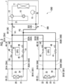
Fig. 5 is a diagram showing an overall configuration of an air conditioning system according to a third embodiment. - As shown in
Fig. 5 , theair conditioning system 1000 includes an outdoor unit 1, a plurality ofindoor units 2, arefrigerant piping 3, and a plurality ofshutoff valve devices 4. The outdoor unit 1, theindoor unit 2, and theshutoff valve device 4 are the same as those in the second embodiment. - In addition, in the example of
Fig. 5 , a plurality of indoor units 2 (for example, twoindoor units refrigerant piping 3. Therefrigerant piping 3 includes amain piping 300 which is a piping on the outdoor unit 1 side, and a plurality of branch pipings 301 (301A, 301B) which branch from the branching points P1 and P2 of themain piping 300 to the respectiveindoor units 2 such that the refrigerant R can circulates between the outdoor unit 1 and the respectiveindoor units - The
main piping 300 includes a refrigerant piping 3 (31, 32) passing through the inside of the outdoor unit 1, a gas-side crossover piping 351 on the outdoor unit 1 side from a branching point P1, and a liquid-side crossover piping 352 on the outdoor unit 1 side from a branching point P2. - The
branch piping 301A causes the refrigerant R to circulate between the outdoor unit 1 and theindoor unit 2A. The branch piping 301A includes a refrigerant piping (33, 34) inside theindoor unit 2A, a gas-side crossover piping 351A on theindoor unit 2A side with respect to a branching point P1, and a liquid-side crossover piping 352A on theindoor unit 2A side with respect to a branching point P2. - The
branch piping 301B causes the refrigerant R to circulate between the outdoor unit 1 and theindoor unit 2B. Thebranch piping 301B includes a refrigerant piping (33, 34) inside theindoor unit 2B, a gas-side crossover piping 351B on theindoor unit 2B side with respect to the branching point P1, and a liquid-side crossover piping 352B on theindoor unit 2B side with respect to the branching point P2. - In addition, the
shutoff valve devices indoor units crossover pipings branch pipings side shutoff valve 40 and the liquid-side shutoff valve 41 of theindoor unit 2A are provided in the gas-side crossover piping 351A and the liquid-side crossover piping 352B of thebranch piping 301A. The gas-side shutoff valve 40 and the liquid-side shutoff valve 41 of theindoor unit 2B are provided in the gas-side crossover piping 351B and the liquid-side crossover piping 352B of the branch piping 301B. - The
shutoff valve device 4A, as in the second embodiment, includes the first gas-side temperature sensor 43 and the second gas-side temperature sensor 44 as the upstream temperature sensor and the downstream temperature sensor of the gas-side shutoff valve 40. In addition, theshutoff valve device 4A includes a first liquid-side temperature sensor 45 and a second liquid-side temperature sensor 46 as an upstream temperature sensor and a downstream temperature sensor of the liquid-side shutoff valve 41. - The process performed by the
CPU 42 of theshutoff valve device 4A is the same as that of the second embodiment. For example, in the cooling operation mode (mode shown inFig. 5 ), theCPU 42 of theshutoff valve device 4A determines whether or not the gas-side shutoff valve 40 provided in the gas-side crossover piping 351A of the branch piping 301A is open or closed, based on the upstream temperature acquired from the first gas-side temperature sensor 43 and the downstream temperature acquired from the second gas-side temperature sensor 44. In addition, theCPU 42 of theshutoff valve device 4A determines whether or not the gas-side shutoff valve 40 provided in the liquid-side crossover piping 352A of the branch piping 301A is open or closed, based on the upstream temperature acquired from the second liquid-side temperature sensor 46 and the downstream temperature acquired from the first liquid-side temperature sensor 45. - In addition, the
shutoff valve device 4B may have the same configuration as theshutoff valve device 4A, or may have the same configuration as a modification example of the second embodiment as shown inFig. 5 . In the example ofFig. 5 , theshutoff valve device 4B uses the firstindoor temperature sensor 22 and the second gas-side temperature sensor 44 as the upstream temperature sensor and the downstream temperature sensor of the gas-side shutoff valve 40. In addition, theshutoff valve device 4B uses the secondindoor temperature sensor 23 and the second liquid-side temperature sensor 46 as the upstream temperature sensor and the downstream temperature sensor of the liquid-side shutoff valve 41. - The process performed by the
CPU 42 of theshutoff valve device 4B is the same as that of the modification example of the second embodiment. For example, in the cooling operation mode (mode shown inFig. 5 ), theCPU 42 of theshutoff valve device 4B determines whether or not the gas-side shutoff valve 40 provided in the gas-side crossover piping 351B of thebranch piping 301B is open or closed, based on the upstream temperature acquired from the firstindoor temperature sensor 22 and the downstream temperature acquired from the second gas-side temperature sensor 44. In addition, theCPU 42 of theshutoff valve device 4B determines whether or not the gas-side shutoff valve 40 provided in the liquid-side crossover piping 352B of thebranch piping 301B is open or closed, based on the upstream temperature acquired from the second liquid-side temperature sensor 46 and the downstream temperature acquired from the secondindoor temperature sensor 23. - As described above, the
air conditioning system 1000 according to the present embodiment includes the outdoor unit 1, the plurality ofindoor units 2, therefrigerant piping 3 having themain piping 300 on the outdoor unit 1 side and the plurality ofbranch pipings 301 on theindoor unit 2 side, theshutoff valves branch pipings 301, the upstream temperature sensor and the downstream temperature sensor provided on the upstream and downstream of the shutoff valve in each of the plurality ofbranch pipings 301, and the CPU 42 (determination unit) that determines whether or not theshutoff valves branch pipings 301 are open or closed, based on the upstream temperature and the downstream temperature measured at the same time. - For example, in the air conditioning system of the related art as disclosed in
PTL 2, the determination (inspection for the shutoff valve) of the opening and closing of each shutoff valve corresponding to each of the plurality of indoor units is performed by a suction pressure sensor provided in the outdoor unit. In this case, when the plurality of shutoff valves are simultaneously subjected to the inspection processing, a pressure fluctuation is simultaneously generated, and thus it is not possible to determine which shutoff valve is normal or abnormal. Therefore, in the air conditioning system of the related art, it is necessary to stop the operation of the other indoor units except for the indoor unit which is an inspection target and to inspect the shutoff valve one by one in order. In this case, it takes time until the inspection of all the shutoff valves is completed. In addition, since the normal operation cannot be continued in the indoor unit (for example, the indoor unit in which the shutoff valve is not provided or the indoor unit that is not the target of the regular inspection this time) which is not an inspection target during the inspection of the other indoor unit, there is a possibility that the convenience of the air conditioning system may be reduced. - In contrast, the
air conditioning system 1000 according to the present embodiment measures and compares the temperature change associated with the opening and closing of theshutoff valves branch pipings 301, as described above. In this way, theair conditioning system 1000 can simultaneously and in parallel inspect the shutoff valves of the plurality ofbranch pipings 301. In addition, theair conditioning system 1000 can inspect each shutoff valve without stopping the operation of theindoor unit 2 which is not an inspection target. Therefore, it is possible to suppress a decrease in convenience of the entire system. - As described above, some embodiments according to the present disclosure have been described, but all of these embodiments are presented as examples and are not intended to limit the scope of the invention. These embodiments can be implemented in various other forms, and various omissions, replacements, and changes can be made without departing from the gist of the invention. These embodiments and modifications thereof are included in the scope of the invention described in the claims and the equivalent scope thereof, as well as in the scope and gist of the invention.
- The above-described embodiment is understood as follows, for example.
-
- (1) According to a first aspect of the present disclosure, an
air conditioner 100 includes: an outdoor unit 1; anindoor unit 2; arefrigerant piping 3 that circulates a refrigerant R between the outdoor unit 1 and theindoor unit 2;shutoff valves refrigerant piping 3 and is capable of shutting off the circulation of the refrigerant R; an upstream temperature sensor that is provided in therefrigerant piping 3 on an upstream side of theshutoff valves shutoff valves refrigerant piping 3 on a downstream side of theshutoff valves shutoff valves determination unit 42 that determines whether or not the shutoff valve is open or closed based on the upstream temperature and the downstream temperature measured at the same time. - Since the
air conditioner 100 performs the determination based on the upstream temperature and the downstream temperature measured at the same time in this way, it is possible to accurately determine whether or not the opening and closing of the shutoff valve is normally performed without being affected by the change in the temperature change amount and the time required for the temperature change due to the change in the characteristics of the indoor unit or the operation point. - (2) According to a second aspect of the present disclosure, in the
air conditioner 100 according to the first aspect, therefrigerant piping 3 is a piping disposed outside the outdoor unit 1 and theindoor unit 2, and includes a crossover piping 35 including an outbound crossover piping that serves as an outbound route for the refrigerant and a return crossover piping that serves as a return route for the refrigerant, and theshutoff valves - Even in a case where the
shutoff valves air conditioner 100 can determine whether or not theshutoff valves shutoff valves air conditioner 100 can determine whether or not theshutoff valves - (3) According to a third aspect of the present disclosure, in the
air conditioner 100 according to the second aspect, at least one of the upstream temperature sensor and the downstream temperature sensor is provided in the crossover piping 35 in which theshutoff valves - In this way, the
air conditioner 100 can shorten a distance between the upstream temperature sensor and the downstream temperature sensor, rather than using the temperature sensors of the outdoor unit 1 and theindoor unit 2. In this manner, theair conditioner 100 can reduce the influence of a length of the crossover piping, and can accurately determine whether or not theshutoff valves - (4) According to a fourth aspect of the present disclosure, in the
air conditioner 100 according to any one of the first to third aspects, at least one of the upstream temperature sensor and the downstream temperature sensor is a temperature sensor that is provided in the outdoor unit 1 or theindoor unit 2. - In this way, the
air conditioner 100 can shorten the distance between the upstream temperature sensor and the downstream temperature sensor or a distance between each temperature sensor and theshutoff valves indoor unit 2. For this reason, theair conditioner 100 can accurately determine whether or not theshutoff valves - (5) According to a fifth aspect of the present disclosure, in the
air conditioner 100 according to the second or third aspect, theshutoff valves - In this way, the
air conditioner 100 can determine whether or not theshutoff valves air conditioner 100 can shorten the distance between the temperature sensors and the distance between the temperature sensor and theshutoff valves shutoff valves - (6) According to a sixth aspect of the present disclosure, the air conditioning system 1000 includes an outdoor unit 1; a plurality of indoor units 2; a refrigerant piping 3 that circulates a refrigerant R between the outdoor unit 1 and each of the plurality of indoor units 2, and includes a main piping 300 that is a piping on an outdoor unit 1 side and a plurality of branch pipings 301 that branch from branching points P1 and P2 of the main piping 300 to each of the plurality of indoor units 2; a plurality of shutoff valves 40 and 41 that are provided in each of the plurality of branch pipings 301 and are capable of individually shutting off circulation of the refrigerant R in the branch piping 301; an upstream temperature sensor that is provided on an upstream side of the shutoff valves 40 and 41 in each of the plurality of branch pipings 301, and measures an upstream temperature representing a temperature of the refrigerant R on the upstream side of the shutoff valves 40 and 41; a downstream temperature sensor that is provided on a downstream side of the shutoff valves 40 and 41 in each of the plurality of branch pipings 301, and measures a downstream temperature representing a temperature of the refrigerant R on the downstream side of the shutoff valves 40 and 41; and a determination unit 42 that determines whether or not the shutoff valves 40 and 41 provided in the branch piping is open or closed based on the upstream temperature and the downstream temperature measured at the same time in the branch piping 301.
- (7) According to a seventh aspect of the present disclosure, a determination method of determining whether or not
shutoff valves air conditioner 100 including an outdoor unit 1, anindoor unit 2, arefrigerant piping 3 that circulates a refrigerant R between the outdoor unit 1 and theindoor unit 2, theshutoff valves refrigerant piping 3 and is capable of shutting off the circulation of the refrigerant R, an upstream temperature sensor that is provided in therefrigerant piping 3 on an upstream side of theshutoff valves refrigerant piping 3 on a downstream side of theshutoff valves shutoff valves - According to the above aspect, it is possible to accurately determine whether or not the shutoff valve is open or closed.
-
- 100: air conditioner
- 1000: air conditioning system
- 1: outdoor unit
- 10: compressor
- 11: four-way valve
- 12: outdoor heat exchanger
- 13: receiver
- 14: first outdoor temperature sensor
- 15: second outdoor temperature sensor
- 2, 2A, 2B: indoor unit
- 20: indoor heat exchanger
- 21: expansion valve
- 22: first indoor temperature sensor
- 23: second indoor temperature sensor
- 3: refrigerant piping
- 300: main piping
- 301, 301A, 301B: branch piping
- 31: gas-side outdoor unit piping
- 32: liquid-side outdoor unit piping
- 33: gas-side indoor unit piping
- 34: liquid-side indoor unit piping
- 35, 35A, 35B: crossover piping
- 351, 351A, 351B: gas-side crossover piping
- 352, 352A, 352B: liquid-side crossover piping
- 4, 4A, 4B: shutoff valve device
- 40: gas-side shutoff valve (shutoff valve)
- 41: liquid-side shutoff valve (shutoff valve)
- 42: CPU (determination unit)
- 43: first gas-side temperature sensor
- 44: second gas-side temperature sensor
- 45: first liquid-side temperature sensor
- 46: second liquid-side temperature sensor
Claims (7)
- An air conditioner comprising:an outdoor unit;an indoor unit;a refrigerant piping that circulates a refrigerant between the outdoor unit and the indoor unit;a shutoff valve that is provided to the refrigerant piping and is capable of shutting off the circulation of the refrigerant;an upstream temperature sensor that is provided in the refrigerant piping on an upstream side of the shutoff valve and measures an upstream temperature representing a temperature of the refrigerant on the upstream side of the shutoff valve;a downstream temperature sensor that is provided in the refrigerant piping on a downstream side of the shutoff valve and measures a downstream temperature representing a temperature of the refrigerant on the downstream side of the shutoff valve; anda determination unit that determines whether or not the shutoff valve is open or closed based on the upstream temperature and the downstream temperature measured at the same time.
- The air conditioner according to Claim 1,
wherein the refrigerant piping is a piping disposed outside the outdoor unit and the indoor unit, and includes a crossover piping including an outbound crossover piping that serves as an outbound route for the refrigerant and a return crossover piping that serves as a return route for the refrigerant, and
the shutoff valve is provided in at least one of the outbound crossover piping and the return crossover piping. - The air conditioner according to Claim 2,
wherein at least one of the upstream temperature sensor and the downstream temperature sensor is provided in the crossover piping in which the shutoff valve is provided. - The air conditioner according to any one of Claims 1 to 3,
wherein at least one of the upstream temperature sensor and the downstream temperature sensor is a temperature sensor that is provided in the outdoor unit or the indoor unit. - The air conditioner according to Claim 2 or 3,
wherein the shutoff valve, the upstream temperature sensor, and the downstream temperature sensor are provided in both the outbound crossover piping and the return crossover piping. - An air conditioning system comprising:an outdoor unit;a plurality of indoor units;a refrigerant piping that circulates a refrigerant between the outdoor unit and each of the plurality of indoor units, and includes a main piping that is a piping on an outdoor unit side and a plurality of branch pipings that branch from a branching point of the main piping to each of the plurality of indoor units;a plurality of shutoff valves that are provided in each of the plurality of branch pipings and are capable of individually shutting off circulation of the refrigerant in the branch piping;an upstream temperature sensor that is provided on an upstream side of the shutoff valve in each of the plurality of branch pipings, and measures an upstream temperature representing a temperature of the refrigerant on the upstream side of the shutoff valve;a downstream temperature sensor that is provided on a downstream side of the shutoff valve in each of the plurality of branch pipings, and measures a downstream temperature representing a temperature of the refrigerant on the downstream side of the shutoff valve; anda determination unit that determines whether or not the shutoff valve provided in the branch piping is open or closed based on the upstream temperature and the downstream temperature measured at the same time in the branch piping.
- A determination method of determining whether or not a shutoff valve of an air conditioner including an outdoor unit, an indoor unit, a refrigerant piping that circulates a refrigerant between the outdoor unit and the indoor unit, the shutoff valve that is provided to the refrigerant piping and is capable of shutting off the circulation of the refrigerant, an upstream temperature sensor that is provided in the refrigerant piping on an upstream side of the shutoff valve, and a downstream temperature sensor that is provided in the refrigerant piping on a downstream side of the shutoff valve is open or closed, the determination method comprising:a step of measuring, via the upstream temperature sensor, an upstream temperature representing a temperature of the refrigerant on the upstream side of the shutoff valve;a step of measuring, via the downstream sensor, a downstream temperature representing a temperature of the refrigerant on the downstream side of the shutoff valve by the downstream temperature sensor; anda step of determining whether or not the shutoff valve is operating, based on the upstream temperature and the downstream temperature measured at the same time.
Applications Claiming Priority (2)
| Application Number | Priority Date | Filing Date | Title |
|---|---|---|---|
| JP2022068008A JP2023158274A (en) | 2022-04-18 | 2022-04-18 | Air conditioners, air conditioning systems, and determination methods |
| PCT/JP2023/015327 WO2023204179A1 (en) | 2022-04-18 | 2023-04-17 | Air conditioner, air conditioning system, and determination method |
Publications (2)
| Publication Number | Publication Date |
|---|---|
| EP4481289A1 true EP4481289A1 (en) | 2024-12-25 |
| EP4481289A4 EP4481289A4 (en) | 2025-06-11 |
Family
ID=88419836
Family Applications (1)
| Application Number | Title | Priority Date | Filing Date |
|---|---|---|---|
| EP23791827.1A Pending EP4481289A4 (en) | 2022-04-18 | 2023-04-17 | Air conditioner, air conditioning system, and determination method |
Country Status (4)
| Country | Link |
|---|---|
| EP (1) | EP4481289A4 (en) |
| JP (1) | JP2023158274A (en) |
| AU (1) | AU2023257077B2 (en) |
| WO (1) | WO2023204179A1 (en) |
Families Citing this family (1)
| Publication number | Priority date | Publication date | Assignee | Title |
|---|---|---|---|---|
| WO2025262742A1 (en) * | 2024-06-17 | 2025-12-26 | 日立ジョンソンコントロールズ空調株式会社 | Refrigeration cycle device and control method |
Family Cites Families (7)
| Publication number | Priority date | Publication date | Assignee | Title |
|---|---|---|---|---|
| JPH08303877A (en) * | 1995-05-10 | 1996-11-22 | Sanyo Electric Co Ltd | Air conditioner |
| CN104236169A (en) * | 2014-09-30 | 2014-12-24 | 宁波奥克斯电气有限公司 | Oil return control method of full fixed frequency multi-line |
| JP6604051B2 (en) | 2015-06-26 | 2019-11-13 | ダイキン工業株式会社 | Air conditioning system |
| JP6645044B2 (en) | 2015-06-26 | 2020-02-12 | ダイキン工業株式会社 | Air conditioning system |
| JP6590706B2 (en) * | 2016-01-14 | 2019-10-16 | 三菱重工サーマルシステムズ株式会社 | Refrigeration cycle apparatus and bypass valve leakage determination control method for refrigeration cycle apparatus |
| JP2019184150A (en) * | 2018-04-09 | 2019-10-24 | ダイキン工業株式会社 | Air conditioner |
| JP7531106B2 (en) | 2020-10-21 | 2024-08-09 | パナソニックIpマネジメント株式会社 | Lighting System |
-
2022
- 2022-04-18 JP JP2022068008A patent/JP2023158274A/en active Pending
-
2023
- 2023-04-17 AU AU2023257077A patent/AU2023257077B2/en active Active
- 2023-04-17 WO PCT/JP2023/015327 patent/WO2023204179A1/en not_active Ceased
- 2023-04-17 EP EP23791827.1A patent/EP4481289A4/en active Pending
Also Published As
| Publication number | Publication date |
|---|---|
| AU2023257077B2 (en) | 2026-01-29 |
| JP2023158274A (en) | 2023-10-30 |
| AU2023257077A1 (en) | 2024-10-03 |
| EP4481289A4 (en) | 2025-06-11 |
| WO2023204179A1 (en) | 2023-10-26 |
Similar Documents
| Publication | Publication Date | Title |
|---|---|---|
| US10852042B2 (en) | Air conditioning system | |
| US11015828B2 (en) | Refrigeration system with utilization unit leak detection | |
| KR100432224B1 (en) | Refrigerant leakage detecting method for air conditioner | |
| US9829230B2 (en) | Air conditioning apparatus | |
| EP3279589B1 (en) | Refrigeration device | |
| US9696078B2 (en) | Refrigeration cycle apparatus | |
| KR102551284B1 (en) | Refrigerator low pressure piping blockage inspection method | |
| EP4015945A1 (en) | Refrigerant leakage determination system | |
| CN110542197B (en) | Detection component for air conditioner, control method and air conditioner | |
| EP3647688A1 (en) | Air-conditioning device | |
| CN111486612A (en) | Multi-split air conditioning system, heating valve leakage detection method and device thereof, and storage medium | |
| JPWO2018225263A1 (en) | Refrigeration equipment and air conditioners | |
| US11781795B2 (en) | Air-conditioning apparatus | |
| AU2023257077A1 (en) | Air conditioner, air conditioning system, and determination method | |
| CN110542196A (en) | Detection assembly for air conditioner, control method, control device and air conditioner | |
| US20160327320A1 (en) | Air-conditioning apparatus and air-conditioning system | |
| EP3361190A1 (en) | Refrigeration cycle device and control method for determination of leaks in bypass valve of refrigeration cycle device | |
| CN106546420A (en) | The valve body detection method of air-conditioning model machine and device, air conditioning system | |
| US11781936B2 (en) | Airtightness evaluation device | |
| EP4675207A1 (en) | Air conditioner | |
| EP4528177A1 (en) | Air conditioning system | |
| EP4592617A1 (en) | Heat pump system | |
| EP4660558A1 (en) | Heat pump apparatus | |
| KR20060117712A (en) | Vacuum tester of air conditioner | |
| CN115962544A (en) | Equipment fault detection method and device and air conditioning equipment |
Legal Events
| Date | Code | Title | Description |
|---|---|---|---|
| STAA | Information on the status of an ep patent application or granted ep patent |
Free format text: STATUS: THE INTERNATIONAL PUBLICATION HAS BEEN MADE |
|
| PUAI | Public reference made under article 153(3) epc to a published international application that has entered the european phase |
Free format text: ORIGINAL CODE: 0009012 |
|
| STAA | Information on the status of an ep patent application or granted ep patent |
Free format text: STATUS: REQUEST FOR EXAMINATION WAS MADE |
|
| 17P | Request for examination filed |
Effective date: 20240919 |
|
| AK | Designated contracting states |
Kind code of ref document: A1 Designated state(s): AL AT BE BG CH CY CZ DE DK EE ES FI FR GB GR HR HU IE IS IT LI LT LU LV MC ME MK MT NL NO PL PT RO RS SE SI SK SM TR |
|
| A4 | Supplementary search report drawn up and despatched |
Effective date: 20250512 |
|
| RIC1 | Information provided on ipc code assigned before grant |
Ipc: F25B 13/00 20060101ALI20250506BHEP Ipc: F25B 49/00 20060101ALI20250506BHEP Ipc: F25B 49/02 20060101ALI20250506BHEP Ipc: F25B 41/24 20210101ALI20250506BHEP Ipc: F24F 11/36 20180101AFI20250506BHEP |
|
| DAV | Request for validation of the european patent (deleted) | ||
| DAX | Request for extension of the european patent (deleted) |