EP4481287A1 - Air-conditioning system - Google Patents
Air-conditioning system Download PDFInfo
- Publication number
- EP4481287A1 EP4481287A1 EP23756093.3A EP23756093A EP4481287A1 EP 4481287 A1 EP4481287 A1 EP 4481287A1 EP 23756093 A EP23756093 A EP 23756093A EP 4481287 A1 EP4481287 A1 EP 4481287A1
- Authority
- EP
- European Patent Office
- Prior art keywords
- refrigerant
- notification
- leak
- conditioning system
- indoor unit
- Prior art date
- Legal status (The legal status is an assumption and is not a legal conclusion. Google has not performed a legal analysis and makes no representation as to the accuracy of the status listed.)
- Pending
Links
Images




Classifications
-
- F—MECHANICAL ENGINEERING; LIGHTING; HEATING; WEAPONS; BLASTING
- F24—HEATING; RANGES; VENTILATING
- F24F—AIR-CONDITIONING; AIR-HUMIDIFICATION; VENTILATION; USE OF AIR CURRENTS FOR SCREENING
- F24F11/00—Control or safety arrangements
- F24F11/30—Control or safety arrangements for purposes related to the operation of the system, e.g. for safety or monitoring
- F24F11/32—Responding to malfunctions or emergencies
- F24F11/36—Responding to malfunctions or emergencies to leakage of heat-exchange fluid
-
- F—MECHANICAL ENGINEERING; LIGHTING; HEATING; WEAPONS; BLASTING
- F24—HEATING; RANGES; VENTILATING
- F24F—AIR-CONDITIONING; AIR-HUMIDIFICATION; VENTILATION; USE OF AIR CURRENTS FOR SCREENING
- F24F11/00—Control or safety arrangements
- F24F11/50—Control or safety arrangements characterised by user interfaces or communication
- F24F11/52—Indication arrangements, e.g. displays
-
- F—MECHANICAL ENGINEERING; LIGHTING; HEATING; WEAPONS; BLASTING
- F24—HEATING; RANGES; VENTILATING
- F24F—AIR-CONDITIONING; AIR-HUMIDIFICATION; VENTILATION; USE OF AIR CURRENTS FOR SCREENING
- F24F11/00—Control or safety arrangements
- F24F11/50—Control or safety arrangements characterised by user interfaces or communication
- F24F11/54—Control or safety arrangements characterised by user interfaces or communication using one central controller connected to several sub-controllers
-
- F—MECHANICAL ENGINEERING; LIGHTING; HEATING; WEAPONS; BLASTING
- F24—HEATING; RANGES; VENTILATING
- F24F—AIR-CONDITIONING; AIR-HUMIDIFICATION; VENTILATION; USE OF AIR CURRENTS FOR SCREENING
- F24F11/00—Control or safety arrangements
- F24F11/62—Control or safety arrangements characterised by the type of control or by internal processing, e.g. using fuzzy logic, adaptive control or estimation of values
- F24F11/63—Electronic processing
-
- F—MECHANICAL ENGINEERING; LIGHTING; HEATING; WEAPONS; BLASTING
- F24—HEATING; RANGES; VENTILATING
- F24F—AIR-CONDITIONING; AIR-HUMIDIFICATION; VENTILATION; USE OF AIR CURRENTS FOR SCREENING
- F24F11/00—Control or safety arrangements
- F24F11/70—Control systems characterised by their outputs; Constructional details thereof
-
- F—MECHANICAL ENGINEERING; LIGHTING; HEATING; WEAPONS; BLASTING
- F24—HEATING; RANGES; VENTILATING
- F24F—AIR-CONDITIONING; AIR-HUMIDIFICATION; VENTILATION; USE OF AIR CURRENTS FOR SCREENING
- F24F11/00—Control or safety arrangements
- F24F11/89—Arrangement or mounting of control or safety devices
Definitions
- the present disclosure relates to an air conditioning system.
- Patent Literature 1 discloses an air conditioner in which an outdoor unit and a plurality of indoor units are connected via refrigerant pipes. A refrigerant leak detection sensor and a remote controller are connected to each of the plurality of indoor units.
- the air conditioner described in Patent Literature 1 transmits detection information on the refrigerant leak to the remote controller in an adjacent room via the indoor unit, the outdoor unit, and the indoor unit in the adjacent room.
- the remote controller in the adjacent room issues an alarm in response to the detection information.
- PATENT LITERATURE 1 Japanese Laid-Open Patent Publication No. 2017-53509
- Patent Literature 1 discloses issuing a refrigerant leak alarm with a remote controller connected to the indoor unit that has detected a leak at the time of a refrigerant leak and the remote controller in the adjacent room.
- a remote controller connected to the indoor unit that has detected a leak at the time of a refrigerant leak and the remote controller in the adjacent room.
- An object of the present disclosure is to provide an air conditioning system capable of appropriately notifying a manager or the like of occurrence of a refrigerant leak to.
- a device and a notification device installed in a management room are used as the first device and the first notification device, respectively, so that the first notification device can make a notification of even a refrigerant leak at a location other than the location where the first device is installed, and quickly let a manager or the like to recognize the refrigerant leak.
- the control device preferably permits operation of the first device and the second device in conjunction with setting of the authority to the first notification device.
- the operation of the first and second devices is permitted in conjunction with the setting of the authority to the first notification device, so that the first and second devices cannot be operated until the authority is set to the first notification device. It is therefore possible to prevent the air conditioning system from operating in a state where the authority is not set.
- a second refrigerant sensor that is provided in the second device and detects the refrigerant
- a second notification device that is communicably connected to the second device and makes a notification of a refrigerant leak on the basis of detection of the refrigerant by the second refrigerant sensor, and an authority to make a notification of a refrigerant leak on the basis of detection of the refrigerant received from other than the second refrigerant sensor is preferably settable to the second notification device.
- the authority can be selectively set to all or any of the first notification device and the second notification device. It is therefore not necessary to set the authority to all of the first and second notification devices, and a notification of the refrigerant leak can be made within a necessary range.
- the control device permits operation of the first device and the second device in conjunction with setting of the authority to the first notification device or the second notification device.
- a third device connected to the first device and including the compressor is preferably further provided, and the control device is preferably provided in the third device.
- the control device can recognize that the notification authority has been given to the first notification device, and the control device can permit operation of the first device and the second device other than the third device.
- the control device since the control device is provided in the third device, when a communication failure occurs between the first device and the third device, the control device cannot recognize that the notification authority is set to the first notification device. Therefore, the first to third devices as a whole can be maintained in a stopped state.
- the first device and the second device preferably share identification information that specifies a group including the first notification device and the first device
- the second device preferably transmits leak detection information and the identification information to the first device on the basis of the detection of the refrigerant by the second refrigerant sensor
- the first device instructs the first notification device to make a notification of the refrigerant leak on the basis of the reception of the leak detection information and the identification information of the group to which the first device belongs.
- the first device receives the leak detection information and the identification information transmitted from the second device, and can instruct the first notification device to make a notification of the refrigerant leak, and the first notification device can make a notification of the refrigerant leak in the second device.
- the identification information is preferably information indicating a model name or a device number of the first device.
- the identification information can be set by using the model name or the device number originally assigned to the first device.
- the first device and the second device are preferably communicably connected by a communication method that allows simultaneous communication.
- This configuration allows the refrigerant leak information and the identification information to be promptly transmitted from the second device to the first device and can achieve early notification.
- the first notification device is preferably a remote controller that operates the first device.
- the first device and the second device are preferably indoor units of an air conditioner.
- FIG. 1 is an overall configuration diagram of an air conditioning system according to an embodiment of the present disclosure.
- An air conditioning system 10 is installed in, for example, a building.
- the air conditioning system 10 includes an air conditioner 11 including an indoor unit 21 installed inside a building and an outdoor unit 22 installed outside the building.
- FIG. 1 shows an air conditioner 11A that operates in a first refrigerant system and an air conditioner 11B that operates in a second refrigerant system.
- the outdoor unit 22 of the air conditioner 11 and a plurality of the indoor units 21 are communicably connected by a first communication line L1.
- the outdoor unit 22 of the first refrigerant system and the outdoor unit 22 of the second refrigerant system are also communicably connected by the first communication line L1.
- a communication method (first communication method) is adopted in which individual communication between the outdoor unit 22 and the indoor units 21 is possible in each refrigerant system, and simultaneous transmission (so-called broadcast) of information from a device of any of the indoor units 21 and the outdoor unit 22 to another device is possible in all the refrigerant systems.
- a remote controller 42 is connected to any of the indoor units 21.
- the remote controller 42 is used to turn on and off operations of the indoor units 21 and the outdoor unit 22 and input operations of a set temperature and the like.
- one remote controller 42 and the indoor unit 21 connected to the remote controller 42 form one group, and the air conditioning system 10 can control the operation of the indoor unit 21 for each group.
- the indoor unit 21 and the remote controller 42 are communicably connected by a second communication line L2.
- a communication method capable of sequential communication is adopted in which the plurality of indoor units 21 can sequentially communicate with the remote controller 42.
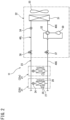
- FIG. 2 is a schematic configuration diagram showing a refrigerant circuit of the air conditioner.
- the air conditioner 11 performs vapor compression refrigeration cycle operation by circulating a refrigerant through a refrigerant circuit 23.
- a refrigerant having a property such as flammability, slight flammability, toxicity, or greenhouse effect, for example, an R32 refrigerant is used.
- the refrigerant circuit 23 includes a compressor 30, a four-way switching valve 32, an outdoor heat exchanger (heat source heat exchanger) 31, an outdoor expansion valve 34, a liquid shutoff valve 36, indoor expansion valves 24, indoor heat exchangers (utilization heat exchangers) 25, a gas shutoff valve 37, and refrigerant pipes 40L and 40G connecting these elements.
- the indoor unit 21 includes the indoor expansion valve 24 and the indoor heat exchanger 25 constituting the refrigerant circuit 23.
- the indoor expansion valve 24 includes an electric expansion valve capable of adjusting a refrigerant pressure and a refrigerant flow rate.
- the indoor heat exchanger 25 is of a cross-fin tube type or a microchannel type, and is used for heat exchange with indoor air.
- the indoor unit 21 further includes an indoor fan 26 and a refrigerant sensor 27.
- the indoor fan 26 is configured to take indoor air into the indoor unit 21, cause the indoor heat exchanger 25 to exchange heat with the taken-in air, and then blow the air into an indoor space.
- the indoor fan 26 includes a motor having a number of operating rotations adjustable in accordance with inverter control.
- the refrigerant sensor 27 detects a refrigerant leaking from the refrigerant circuit 23.
- the refrigerant sensor 27 is provided near a refrigerant pipe inside the indoor unit 21.
- the refrigerant sensor 27 may be provided in the remote controller 42 to be described below, a ceiling, a wall, a floor, or the like in the indoor space.
- the outdoor unit 22 includes the compressor 30, the four-way switching valve 32, the outdoor heat exchanger 31, the outdoor expansion valve 34, the liquid shutoff valve 36, and the gas shutoff valve 37 that are included in the refrigerant circuit 23.
- the compressor 30 sucks a low-pressure gas refrigerant and discharges a high-pressure gas refrigerant.
- the compressor 30 includes a motor having a number of operating rotations adjustable in accordance with inverter control.
- the compressor 30 is of a variable capacity type (performance variable type) having capacity (performance) variable in accordance with inverter control of the motor.
- the compressor 30 may be of a constant capacity type.
- There may alternatively be provided a plurality of compressors 30. In this case, compressors of a variable capacity type and compressors of a constant capacity type may coexist.
- the four-way switching valve 32 reverses a refrigerant flow in the refrigerant pipe, and switches and supplies the refrigerant discharged from the compressor 30 to either the outdoor heat exchanger 31 or the indoor heat exchanger 25.
- the air conditioner 11 can switch between a cooling operation and a heating operation.
- the outdoor heat exchanger 31 is, for example, a cross fin tube type or microchannel type heat exchanger, and is used for exchanging heat with a refrigerant by using air as a heat source.
- the outdoor expansion valve 34 includes an electric expansion valve capable of adjusting the refrigerant pressure and the refrigerant flow rate.
- the liquid shutoff valve 36 is a manually operated on-off valve.
- the gas shutoff valve 37 is also a manually operated on-off valve.
- the outdoor unit 22 further includes an outdoor fan 33.
- the outdoor fan 33 includes a motor having a number of operating rotations adjustable in accordance with inverter control.
- the outdoor fan 33 is configured to take outdoor air into the outdoor unit 22, cause the outdoor heat exchanger 31 to exchange heat with the taken-in air, and then blow the air out of the outdoor unit 22.
- the four-way switching valve 32 is maintained in a state indicated by solid lines in FIG. 2 .
- a high-temperature and high-pressure gaseous refrigerant discharged from the compressor 30 flows into the outdoor heat exchanger 31 through the four-way switching valve 32, and exchanges heat with outdoor air by operation of the outdoor fan 33 to dissipate heat.
- the refrigerant having dissipated heat passes through the outdoor expansion valve 34 in a fully open state and flows into each indoor unit 21.
- the refrigerant in the indoor unit 21 is decompressed to have predetermined low pressure at the indoor expansion valve 24, and further exchanges heat with indoor air in the indoor heat exchanger 25 to be evaporated.
- the indoor fan 26 causes the indoor air cooled due to evaporation of the refrigerant to blow indoors so as to cool the indoor space.
- the refrigerant evaporated in the indoor heat exchanger 25 returns to the outdoor unit 22 via the gas refrigerant pipe 40G, passes through the four-way switching valve 32, and is sucked into the compressor 30.
- the four-way switching valve 32 When the air conditioner 11 performs the heating operation, the four-way switching valve 32 is maintained in a state indicated by broken lines in FIG. 2 .
- the high-temperature and high-pressure gas refrigerant discharged from the compressor 30 passes through the four-way switching valve 32 and flows into the indoor heat exchanger 25 of each of the indoor units 21.
- the indoor heat exchanger 25 In the indoor heat exchanger 25, the refrigerant exchanges heat with indoor air to dissipate heat.
- the indoor air heated by the heat dissipation of the refrigerant is blown into the indoor space by the indoor fan 26 to heat the indoor space.
- the refrigerant liquefied in the indoor heat exchanger 25 returns to the outdoor unit 22 through the liquid refrigerant pipe 40L, is decompressed to a predetermined low pressure by the outdoor expansion valve 34, and further exchanges heat with outdoor air in the outdoor heat exchanger 31 to evaporate.
- the refrigerant evaporated and vaporized by the outdoor heat exchanger 31 is sucked into the compressor 30 through the four-way switching valve 32.
- FIG. 3 is a block diagram of a control system of the air conditioner.
- the indoor unit 21 includes a control device 29 as a control system component.
- the control device 29 includes a microcomputer or the like having a control unit 29a such as a CPU and a storage 29b such as a RAM or a ROM.
- the control device 29 may include an integrated circuit such as an FPGA or an ASIC.
- the control device 29 controls the operation of the indoor fan 26 and the indoor expansion valve 24 described above.
- the control device 29 also receives a signal transmitted from the refrigerant sensor 27.
- the refrigerant sensor 27 transmits a detection signal of the refrigerant leaking from the refrigerant circuit 23 to the control device 29.
- the remote controller 42 is communicably connected to the control device 29 in the indoor unit 21.
- a user can operate the remote controller 42 to turn on or off the air conditioner 11, to input set temperature, and the like.
- the remote controller 42 according to the embodiment includes a control device 42a and a display panel (display unit) 42b.
- the control device 42a includes a microcomputer or the like having a control unit such as a CPU and a storage such as a RAM or a ROM.
- the control device may include an integrated circuit such as an FPGA or an ASIC.
- the display panel 42b functions as a notification unit that notifies that the refrigerant has been detected by the refrigerant sensor 27.
- the outdoor unit 22 includes the control device 39.
- the control device 39 includes a microcomputer or the like having a control unit 39a such as a CPU and a storage 39b such as a RAM or a ROM.
- the control device 39 may include an integrated circuit such as an FPGA or an ASIC.
- the control device 39 controls operations of the compressor 30, the outdoor fan 33, and the outdoor expansion valve 34.
- the control device 39 transmits a control signal for controlling the operations of the indoor fan 26 and the indoor expansion valve 24 of each of the plurality of indoor units 21 to the control device 29 of the indoor unit 21.
- the slightly flammable R32 refrigerant is used as the refrigerant. Therefore, when the refrigerant leaks from the refrigerant circuit 23 of the indoor unit 21, it is desirable to notify the user or the like of the leak as soon as possible.
- the refrigerant sensor 27 detects the refrigerant, the information (leak detection information) is transmitted from the control device 29 of the indoor unit 21 to the control device 42a of the remote controller 42, and a notification of the refrigerant leak is made by displaying an alarm on the display panel 42b of the remote controller 42. Therefore, the user who uses the room can recognize that the refrigerant has leaked.
- the air conditioning system 10 including the plurality of indoor units 21 and the remote controller 42 potentially has the following problems.
- Standard of air conditioner in Japan (Standard of Japan Refrigeration and Air Conditioning Industry Association (JRA Standard)) requires notifying a building manager or the like when a refrigerant leak occurs.
- JRA Standard Joint of Japan Refrigeration and Air Conditioning Industry Association
- the centralized management device can receive the information and notify the manager of the information.
- small and medium-scale buildings and the like often do not include such a centralized management device, and thus have a difficulty in notifying the manager or the like of the refrigerant leak. Therefore, there is a possibility that a response to the refrigerant leak is delayed.
- the indoor units 21 When the plurality of indoor units 21 communicates with the remote controller 42 by the polling method as in the air conditioning system 10 according to the present embodiment, the indoor units 21 cannot necessarily communicate with the remote controller 42 immediately after detecting the refrigerant, and performs communication when its turn comes. Therefore, there is a possibility that notification by the remote controller 42 is delayed.
- the air conditioning system 10 takes the following measures in view of the first and second problems.
- any of the remote controllers 42 is configured to be settable for management.
- a contractor or a service person can perform management setting on the specific remote controller 42 when or after the air conditioning system 10 is installed.
- the management setting gives the specific remote controller 42 an authority (hereinafter, also referred to as "notification authority") to make a notification of the refrigerant leak on the basis of the detection of the refrigerant received from other than the refrigerant sensor 27 of the indoor unit 21 connected to the remote controller 42.
- the remote controller 42 set for management can make a notification of the refrigerant leak detected in another indoor unit 21 other than the group to which the remote controller 42 belongs, and the manager in the management room can be immediately notified of the occurrence of the refrigerant leak.
- the air conditioning system 10 is configured to be able to instruct the remote controller 42 to make a notification of the refrigerant leak from all the indoor units 21 included in the group when the refrigerant is detected in any of the plurality of indoor units 21 in each group. Therefore, regardless of the order of communication with the remote controller 42, the indoor unit 21 that first communicates with the remote controller 42 in the group can issue an instruction to make a notification of a refrigerant leak to the remote controller 42, and the remote controller 42 can make a notification of the occurrence of the refrigerant leak and notify the user in the indoor space of the refrigerant leak without delay.
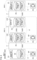
- FIG. 4 is a block diagram for describing a mechanism of notification of a refrigerant leak.
- some groups A, B, and C included in the air conditioning system 10 are extracted and illustrated.
- Each of the groups A, B, and C includes one or a plurality of indoor units 21A, 21B1, 21B2, and 21C and remote controllers 42A, 42B, and 42C.
- only one indoor unit 21A or 21C is illustrated in the group A and the group C, a plurality of indoor units may be included.
- the indoor unit 21A and the remote controller 42A included in the group A are set for management.
- the indoor unit 21A and the remote controller 42A included in the group A can be installed in, for example, a management room of a building.
- the storages 29b of the indoor units 21A, 21B 1, 21B2, and 21C included in the groups A, B, and C store identification information for specifying the groups A, B, and C to which the indoor units 21A, 21B1, 21B2, and 21C belong.
- the indoor unit 21A of the group A stores identification information of the group A.
- the indoor units 21B1 and 21B2 of the group B store identification information of the group B.
- the indoor unit 21C of the group C stores identification information of the group C.
- the same identification information is shared by the indoor units 21B1 and 21B2 which belong to the same group B.
- the storages 29b of the indoor units 21B 1, 21B2, and 21C in the groups B and C belonging to groups other than the management group A store the identification information of the group A set for management in addition to the identification information of their own groups B and C. Therefore, the identification information of the management group A is shared by all the indoor units 21A, 21B1,21B2, and 21C.
- a model name and a device number of the indoor unit included in each of the groups A, B, and C are used as the identification information of each of the groups A, B, and C.
- the model names and the device numbers of the representative indoor units 21 A, 21B1, and 21C are adopted as the identification information.
- the representative indoor unit is an indoor unit generally called a "master unit", and for example, an indoor unit that supplies power to the remote controller 42 is adopted.
- the device number is a unique number assigned to each indoor unit 21, and corresponds to, for example, a manufacturing number, a communication address, or the like.
- FIG. 5 is a flowchart of a processing procedure for sharing the identification information of each group among the plurality of indoor units.
- FIG. 5 as an example, a procedure for sharing the identification information among the plurality of indoor units 21B1 and 21B2 in the group B in FIG. 4 will be described.
- the indoor unit 21B1 as a representative in the group B transmits the identification information (model name and device number) of the indoor unit 21B1 to the remote controller 42B (step S11). This transmission of the identification information is performed by communication by the polling method.
- the remote controller 42B Upon receiving the identification information, the remote controller 42B transmits the identification information of the representative indoor unit 21B1 to the other indoor unit 21B2 in the group B (step S12). This transmission of the identification information is also performed by communication by the polling method.
- the other indoor unit 21B2 that has received the identification information stores the identification information in the storage 29b and shares the identification information of the indoor unit 21B1 (step S13).
- FIG. 6 is a flowchart of a processing procedure for sharing the identification information of the management group among the plurality of indoor units.
- the remote controller 42A transmits information (setting information) indicating that the notification authority has been set to the indoor unit 21A which is a representative of the group A (step S22). This transmission is performed by communication by the polling method.
- the indoor unit 21A having received the setting information transmits the model name and device number of the indoor unit 21A, which are identification information of the group A, to the other indoor units 21B1, 21B2, and 21C as a representative of the management group A (step S23).
- This transmission is performed by communication by a broadcast method. Therefore, the identification information of the indoor unit 21A set for management is also transmitted to the outdoor unit 22. The handling of the identification information transmitted to the outdoor unit 22 will be described later.
- the other indoor units 21B1, 21B2, and 21C store the received identification information of the management group Ain the storage 29b, and all the indoor units 21A, 21B1, 21B2, and 21C share the identification information (step S24).
- FIG. 7 is a flowchart illustrating a control procedure of the indoor unit.
- FIG. 7 illustrates control procedures of both the indoor unit 21 that has detected a refrigerant leak and the indoor unit 21 that has received information indicating a refrigerant leak from another indoor unit 21. This control procedure is performed by the control device 29 of the indoor unit 21.
- Each indoor unit 21 of the air conditioning system 10 determines whether the refrigerant leaking from the refrigerant sensor 27 has been detected (step S31). When the determination in step S31 is affirmative (Yes), the indoor unit 21 transmits the refrigerant leak information including the following three pieces of information (a) to (c) to the other indoor units 21 by the broadcast method.
- the information (a) is a signal generated when the refrigerant leaks from the indoor unit 21 and the refrigerant sensor 27 provided in the indoor unit 21 detects the refrigerant, and is also called a leak flag.
- the indoor unit 21 that has received the leak detection information can recognize that the refrigerant leaks from another indoor unit 21 other than the indoor unit itself.
- the information (b) is identification information (model name and device number) of the representative indoor unit 21 shared in the group by the procedure illustrated in FIG. 5 .
- the information (c) is identification information (model name and device number) of the representative indoor unit 21 in the management group shared by all the indoor units 21 in accordance with the procedure illustrated in FIG. 6 .
- the indoor unit 21 that has detected the refrigerant leak instructs the remote controller 42 to make a notification of the refrigerant leak (step S33).
- each indoor unit 21 of the air conditioning system 10 determines whether the refrigerant leak information has been received from the other indoor units 21 (step S41).
- the indoor unit 21 compares the identification information of the group to which the indoor unit 21 belongs with the two pieces of transmitted identification information (step S42).
- the processing proceeds to step S43, and when the determination is negative (No), the processing returns to step S41.
- the indoor unit 21 can recognize that the refrigerant leaks from the other indoor units 21 in the same group as the indoor unit 21.
- the indoor unit 21B1 illustrated in FIG. 4 transmits the refrigerant leak information (leak detection information and identification information of the group A and the group B) and the indoor unit 21B2 receives the refrigerant leak information
- the indoor unit 21B2 compares the identification information of its own group B with the received identification information of the group A and the group B. Since the indoor unit 21B2 has received the identification information that matches the identification information of its own group B, the indoor unit 21B2 can recognize that the refrigerant leaks from the other indoor unit 21B1 in the same group B.
- the indoor unit 21 instructs the remote controller 42 to make a notification of the refrigerant leak.
- both the indoor unit 21 in which the refrigerant has leaked and the other indoor units 21 in the same group can instruct the remote controller 42 in the group to make a notification of the refrigerant leak (steps S33 and S43). Therefore, after the refrigerant is detected, the indoor unit 21 that first becomes communicable with the remote controller 42 can instruct the remote controller 42 to make a notification of the refrigerant leak, and can prevent delay in notification of the refrigerant leak by the remote controller 42.
- the indoor unit 21B 1 illustrated in FIG. 4 transmits the refrigerant leak information (leak detection information and identification information of the group A and the group B) and the indoor unit 21A in the management group A receives the refrigerant leak information
- the indoor unit 21A compares the identification information of its own group A with the received identification information of the group A and the group B (step S42). Since the indoor unit 21A has received the identification information that matches the identification information of its own group A, the indoor unit 21A instructs the remote controller 42A in the management group A to make a notification of the refrigerant leak at its own communication opportunity in step S43 in FIG. 7 .
- a manager in a management room of a building or the like can confirm that a refrigerant leak occurs in any one of the indoor units 21 in the air conditioning system 10, and can take an appropriate measure against the refrigerant leak.
- the indoor units 21A When a plurality of indoor units 21A is included in the management group A, all the indoor units 21A receive the identification information that matches the identification information of their own group A. Thus, the indoor units 21A each instruct the remote controller 42A in the management group A to make a notification of the refrigerant leak at their own communication opportunity. Therefore, after the refrigerant is detected, the indoor unit 21A that first becomes communicable with the remote controller 42A can instruct to make a notification of the refrigerant leak, and can prevent delay in notification by the remote controller 42A.
- the indoor unit 21C illustrated in FIG. 4 receives the refrigerant leak information transmitted from the indoor unit 21B1, the identification information of its own group C does not match the received identification information of the groups A and B, and thus, does not instruct the remote controller 42C to make a notification. Therefore, the processing returns from step S42 to step S41 in FIG. 7 .
- the air conditioning system 10 has an interlock function that permits the operation of the indoor unit 21 in conjunction with the notification authority set to any of the plurality of remote controllers 42.
- the outdoor unit 22 receives the identification information transmitted from the indoor unit 21A, which is the representative of the management group A, by the broadcast method.
- the outdoor unit 22 can confirm that the notification authority has been given to any of the remote controllers 42 by receiving the identification information, and can permit the operation of the indoor unit 21 on the basis of the reception of the identification information.
- the operation of the indoor unit 21 is permitted in a state where the notification authority is not set for any of the remote controllers 42, it is impossible to notify the manager of the occurrence of the refrigerant leak, and it is difficult to comply with the JRA standard.
- the operation of the indoor unit 21 is not permitted unless the notification authority is set to any of the remote controllers 42. Therefore, the air conditioning system 10 can be prevented from operating in a state where the notification authority is not set. It is also possible to prevent setting of the notification authority from being forgotten.
- the control device 39 of the outdoor unit 22 can permit the operation of the indoor unit 21 by setting the notification authority to at least one remote controller 42 in the air conditioning system 10.
- the interlock function as described above may be provided in the control device 29 of the indoor unit 21.
- the control device 29 of the indoor unit 21 permits the operation of the indoor unit 21.
- the control device 29 can recognize that the notification authority has been set to the remote controller 42. Therefore, there is a possibility that the control device 29 can permit the operation of the indoor unit 21 other than the outdoor unit 22.
- the control device 39 of the outdoor unit 22 has an interlock function, such an inconvenience does not occur.
- the refrigerant sensor 27 is provided in the indoor unit 21 of the air conditioner 11, and the notification of the refrigerant leak in the indoor unit 21 is made.
- a refrigerant sensor may detect a refrigerant leak in another device through which the refrigerant flows, for example, an outside air processor or a ventilator, and a remote controller may make a notification of the refrigerant leak.
- the notification of the refrigerant leak is made by using the display panel 42b of the remote controller 42, but the present disclosure is not limited to this configuration, and the notification of the refrigerant leak may be made by light or sound by using a light or a buzzer provided in the remote controller 42.
- a notification device for making a notification of a refrigerant leak is not limited to the remote controller 42, and may be constituted by a device dedicated to notification.
- the identification information of each of the groups A, B, and C is not limited to the model name and the device number of the representative indoor units 21 A, 21B1, and 21 C, and may be a model name and a device number of an indoor unit other than the representative indoor unit.
- the identification information may include only one of the model name or the device number.
- the notification authority for management can be set for all the remote controllers 42 in the air conditioning system 10. Therefore, the notification authority for management can be set by selecting any one or plurality of remote controllers 42 from all the remote controllers 42. As a result, it is possible to notify only necessary persons such as a manager and a person in a specific room of the refrigerant leak.
- the interlock function of permitting operation of the indoor unit 21 in conjunction with the setting of the notification authority is only required to function when the notification authority is set for at least one remote controller 42.
- the first device 21A and the first notification device 42A are used as the device and the notification device installed in the management room, respectively, so that the first notification device 42A can make a notification of even a refrigerant leak at a location other than the location where the first device 21A is installed, and quickly notify the manager or the like of the refrigerant leak.
- the control device 39 or 29 permits the operation of the first device 21A and the second devices 21B 1, 21B2, and 21C in conjunction with the setting of the authority to the first notification device 42A.
- the operation of the first and second devices 21A, 21B 1, 21B2, and 21C is permitted in conjunction with the setting of the authority to the first notification device 42A, so that the first and second devices 21A, 21B 1, 21B2, and 21C cannot be operated until the notification authority is set to the first notification device 42A. It is therefore possible to prevent the air conditioning system from operating in a state where the notification authority is not set. It is also possible to prevent setting of the notification authority from being forgotten.
- the air conditioning system 10 includes a second refrigerant sensor (for example, the refrigerant sensor 27 of the group B or the group C in FIG. 4 ) that is provided in the second devices 21B 1, 21B2, and 21C and detects the refrigerant, and a second notification device (for example, remote controller 42B or 42C in FIG.
- a second refrigerant sensor for example, the refrigerant sensor 27 of the group B or the group C in FIG. 4
- a second notification device for example, remote controller 42B or 42C in FIG.
- the authority can be selectively set to all or any of the first notification device 42A and the second notification devices 42B and 42C. It is therefore not necessary to set the authority to all of the first and second notification devices 42A and 42B and 42C, and the notification of the refrigerant leak can be made within a necessary range.
- control devices 39 and 29 permit the operation of the first device 21A and the second devices 21B 1, 21B2, and 21C in conjunction with the setting of the authority to the first notification device 42A or the second notification devices 42B and 42C.
- the authority is set to only one of the first notification device 42A or the second notification devices 42B and 42C, it is possible to notify the manager of the refrigerant leak, so that the operation of the first device 21A and the second devices 21B1, 21B2, and 21C can be permitted.
- a third device (for example, the outdoor unit 22) connected to the first device 21A and including the compressor 30 is further provided, and the control device 39 is provided in the third device 22.
- the control device can recognize that the notification authority has been given to the first notification device 42A, and the control device can permit operation of the first device 21A and the second devices 21B 1, 21B2, and 21C other than the third device 22.
- the control device 39 since the control device 39 is provided in the third device 22, when a communication failure occurs between the first device 21A and the third device 22, the control device 39 cannot recognize that the notification authority is set to the first notification device 42A. Therefore, the first device 21A, the second devices 21B 1, 21B2, and 21C, and the third device 22 as a whole can be maintained in a stopped state.
- the first device 21A and the second devices 21B 1, 21B2, and 21C share the identification information that specifies the group A including the first notification device 42A and the first device 21A
- the second devices 21B1, 21B2, and 21C transmit the leak detection information and the identification information to the first device 21A on the basis of the detection of the refrigerant by the second refrigerant sensor 27, and the first device 21A instructs the first notification device 42A to make a notification of the refrigerant leak on the basis of the reception of the refrigerant detection information and the identification information of the group A to which the first device 21A belongs.
- the first device 21A receives the leak detection information and the identification information transmitted from the second devices 21B 1, 21B2, and 21C, and can instruct the first notification device 42A to make a notification of the refrigerant leak, and the first notification device 42A can make a notification of the refrigerant leak in the second device 21B1.
- the identification information is information indicating the model name or the device number of the first device 21A.
- the identification information can be set by using the model name or the device number originally assigned to the first device 21A.
- the first device 21A and the second devices 21B1, 21B2, and 21C are communicably connected by a communication method that allows simultaneous communication.
- This configuration allows the refrigerant leak information and the identification information to be promptly transmitted from the second device 21B 1 to the first device 21A and can achieve early notification.
- the first notification device 42A is a remote controller that operates the first device 21A. Accordingly, the notification of the refrigerant leak can be made by using the remote controller 42Athat operates the first device 21A.
- the interlock function of the air conditioning system is not limited to a method in conjunction with the setting of the notification authority to the notification device, and other methods can be adopted.
- the air conditioning system may be configured to permit operation of the indoor unit when at least one notification device is communicably connected.
- the notification authority is not set to any notification device.
- all the notification devices may make a notification of the refrigerant leak on the basis of the reception of the leak detection information when the refrigerant is detected by any of the refrigerant sensors.
- the notification device is not limited to the remote controller, and may be a centralized device that centrally controls the outdoor unit and the indoor unit of the air conditioning system.
Landscapes
- Engineering & Computer Science (AREA)
- Chemical & Material Sciences (AREA)
- Combustion & Propulsion (AREA)
- Mechanical Engineering (AREA)
- General Engineering & Computer Science (AREA)
- Human Computer Interaction (AREA)
- Signal Processing (AREA)
- Physics & Mathematics (AREA)
- Fuzzy Systems (AREA)
- Mathematical Physics (AREA)
- Air Conditioning Control Device (AREA)
Abstract
Description
- The present disclosure relates to an air conditioning system.
- Patent Literature 1 below discloses an air conditioner in which an outdoor unit and a plurality of indoor units are connected via refrigerant pipes. A refrigerant leak detection sensor and a remote controller are connected to each of the plurality of indoor units.
- When the refrigerant leak detection sensor detects a refrigerant leak, the air conditioner described in Patent Literature 1 transmits detection information on the refrigerant leak to the remote controller in an adjacent room via the indoor unit, the outdoor unit, and the indoor unit in the adjacent room. The remote controller in the adjacent room issues an alarm in response to the detection information.
- PATENT LITERATURE 1:
Japanese Laid-Open Patent Publication No. 2017-53509 - Patent Literature 1 discloses issuing a refrigerant leak alarm with a remote controller connected to the indoor unit that has detected a leak at the time of a refrigerant leak and the remote controller in the adjacent room. However, there is not always a person who can take action after the leak occurs in the room in which the leak has occurred and the adjacent room.
- An object of the present disclosure is to provide an air conditioning system capable of appropriately notifying a manager or the like of occurrence of a refrigerant leak to.
-
- (1) An air conditioning system of the present disclosure includes a first device and a second device that are communicably connected to each other and through which a refrigerant flows, a first refrigerant sensor that is provided in the first device and detects the refrigerant, a first notification device that is communicably connected to the first device and makes a notification of a refrigerant leak on the basis of detection of the refrigerant by the first refrigerant sensor, and a control device that controls the first device and the second device, in which an authority to make a notification of a refrigerant leak on the basis of detection of the refrigerant received from other than the first refrigerant sensor is settable to the first notification device.
- In the air conditioning system having the above configuration, for example, a device and a notification device installed in a management room are used as the first device and the first notification device, respectively, so that the first notification device can make a notification of even a refrigerant leak at a location other than the location where the first device is installed, and quickly let a manager or the like to recognize the refrigerant leak.
- (2) The control device preferably permits operation of the first device and the second device in conjunction with setting of the authority to the first notification device.
- In this configuration, the operation of the first and second devices is permitted in conjunction with the setting of the authority to the first notification device, so that the first and second devices cannot be operated until the authority is set to the first notification device. It is therefore possible to prevent the air conditioning system from operating in a state where the authority is not set.
- (3) There is preferably provided a second refrigerant sensor that is provided in the second device and detects the refrigerant, and a second notification device that is communicably connected to the second device and makes a notification of a refrigerant leak on the basis of detection of the refrigerant by the second refrigerant sensor, and an authority to make a notification of a refrigerant leak on the basis of detection of the refrigerant received from other than the second refrigerant sensor is preferably settable to the second notification device.
- In this configuration, the authority can be selectively set to all or any of the first notification device and the second notification device. It is therefore not necessary to set the authority to all of the first and second notification devices, and a notification of the refrigerant leak can be made within a necessary range.
- (4) The control device permits operation of the first device and the second device in conjunction with setting of the authority to the first notification device or the second notification device.
- In this configuration, when the authority is set to only one of the first notification device or the second notification device, it is possible to notify the manager of the refrigerant leak, so that the operation of the first device and the second device can be permitted.
- (5) A third device connected to the first device and including the compressor is preferably further provided, and the control device is preferably provided in the third device.
- In this configuration, if the control device is provided in the first device, even if a communication failure occurs between the first device and the third device, the control device can recognize that the notification authority has been given to the first notification device, and the control device can permit operation of the first device and the second device other than the third device. In the present disclosure, since the control device is provided in the third device, when a communication failure occurs between the first device and the third device, the control device cannot recognize that the notification authority is set to the first notification device. Therefore, the first to third devices as a whole can be maintained in a stopped state.
- (6) When the authority is set to the first notification device, the first device and the second device preferably share identification information that specifies a group including the first notification device and the first device, the second device preferably transmits leak detection information and the identification information to the first device on the basis of the detection of the refrigerant by the second refrigerant sensor, and the first device instructs the first notification device to make a notification of the refrigerant leak on the basis of the reception of the leak detection information and the identification information of the group to which the first device belongs.
- In this configuration, the first device receives the leak detection information and the identification information transmitted from the second device, and can instruct the first notification device to make a notification of the refrigerant leak, and the first notification device can make a notification of the refrigerant leak in the second device.
- (7) The identification information is preferably information indicating a model name or a device number of the first device.
- In this configuration, the identification information can be set by using the model name or the device number originally assigned to the first device.
- (8) The first device and the second device are preferably communicably connected by a communication method that allows simultaneous communication.
- This configuration allows the refrigerant leak information and the identification information to be promptly transmitted from the second device to the first device and can achieve early notification.
- (9) The first notification device is preferably a remote controller that operates the first device.
- (10) The first device and the second device are preferably indoor units of an air conditioner.
-
-
FIG. 1 is an overall configuration diagram of an air conditioning system according to an embodiment of the present disclosure. -
FIG. 2 is a schematic configuration diagram showing a refrigerant circuit of an air conditioner. -
FIG. 3 is a block diagram of a control system of the air conditioner. -
FIG. 4 is a block diagram for describing a mechanism of notification of a refrigerant leak. -
FIG. 5 is a flowchart of a processing procedure for sharing identification information of each group among a plurality of indoor units. -
FIG. 6 is a flowchart of a processing procedure for sharing identification information of a management group among a plurality of indoor units. -
FIG. 7 is a flowchart of a control procedure of an indoor unit. - Embodiments of an air conditioning system will be described in detail below with reference to the accompanying drawings.
-
FIG. 1 is an overall configuration diagram of an air conditioning system according to an embodiment of the present disclosure. - An
air conditioning system 10 according to the present embodiment is installed in, for example, a building. Theair conditioning system 10 includes anair conditioner 11 including anindoor unit 21 installed inside a building and anoutdoor unit 22 installed outside the building.FIG. 1 shows anair conditioner 11A that operates in a first refrigerant system and anair conditioner 11B that operates in a second refrigerant system. - In each refrigerant system, the
outdoor unit 22 of theair conditioner 11 and a plurality of theindoor units 21 are communicably connected by a first communication line L1. Theoutdoor unit 22 of the first refrigerant system and theoutdoor unit 22 of the second refrigerant system are also communicably connected by the first communication line L1. In the communication through the first communication line L1, a communication method (first communication method) is adopted in which individual communication between theoutdoor unit 22 and theindoor units 21 is possible in each refrigerant system, and simultaneous transmission (so-called broadcast) of information from a device of any of theindoor units 21 and theoutdoor unit 22 to another device is possible in all the refrigerant systems. - In each refrigerant system, a
remote controller 42 is connected to any of theindoor units 21. Theremote controller 42 is used to turn on and off operations of theindoor units 21 and theoutdoor unit 22 and input operations of a set temperature and the like. In the present embodiment, as indicated by surrounding a dotted frame inFIG. 1 , oneremote controller 42 and theindoor unit 21 connected to theremote controller 42 form one group, and theair conditioning system 10 can control the operation of theindoor unit 21 for each group. Oneindoor unit 21, which is generally called a "master unit" and serves a representative, is defined in each group. - In each group, the
indoor unit 21 and theremote controller 42 are communicably connected by a second communication line L2. In the communication through the second communication line L2, a communication method (second communication method or a so-called polling method) capable of sequential communication is adopted in which the plurality ofindoor units 21 can sequentially communicate with theremote controller 42. -
FIG. 2 is a schematic configuration diagram showing a refrigerant circuit of the air conditioner. - The
air conditioner 11 performs vapor compression refrigeration cycle operation by circulating a refrigerant through arefrigerant circuit 23. In the present embodiment, as the refrigerant, a refrigerant having a property such as flammability, slight flammability, toxicity, or greenhouse effect, for example, an R32 refrigerant is used. - The
refrigerant circuit 23 includes acompressor 30, a four-way switching valve 32, an outdoor heat exchanger (heat source heat exchanger) 31, anoutdoor expansion valve 34, aliquid shutoff valve 36,indoor expansion valves 24, indoor heat exchangers (utilization heat exchangers) 25, agas shutoff valve 37, andrefrigerant pipes - The
indoor unit 21 includes theindoor expansion valve 24 and theindoor heat exchanger 25 constituting therefrigerant circuit 23. Theindoor expansion valve 24 includes an electric expansion valve capable of adjusting a refrigerant pressure and a refrigerant flow rate. Theindoor heat exchanger 25 is of a cross-fin tube type or a microchannel type, and is used for heat exchange with indoor air. - The
indoor unit 21 further includes anindoor fan 26 and arefrigerant sensor 27. Theindoor fan 26 is configured to take indoor air into theindoor unit 21, cause theindoor heat exchanger 25 to exchange heat with the taken-in air, and then blow the air into an indoor space. Theindoor fan 26 includes a motor having a number of operating rotations adjustable in accordance with inverter control. - The
refrigerant sensor 27 detects a refrigerant leaking from therefrigerant circuit 23. Therefrigerant sensor 27 is provided near a refrigerant pipe inside theindoor unit 21. Alternatively, therefrigerant sensor 27 may be provided in theremote controller 42 to be described below, a ceiling, a wall, a floor, or the like in the indoor space. - The
outdoor unit 22 includes thecompressor 30, the four-way switching valve 32, theoutdoor heat exchanger 31, theoutdoor expansion valve 34, theliquid shutoff valve 36, and thegas shutoff valve 37 that are included in therefrigerant circuit 23. - The
compressor 30 sucks a low-pressure gas refrigerant and discharges a high-pressure gas refrigerant. Thecompressor 30 includes a motor having a number of operating rotations adjustable in accordance with inverter control. Thecompressor 30 is of a variable capacity type (performance variable type) having capacity (performance) variable in accordance with inverter control of the motor. Alternatively, thecompressor 30 may be of a constant capacity type. There may alternatively be provided a plurality ofcompressors 30. In this case, compressors of a variable capacity type and compressors of a constant capacity type may coexist. - The four-
way switching valve 32 reverses a refrigerant flow in the refrigerant pipe, and switches and supplies the refrigerant discharged from thecompressor 30 to either theoutdoor heat exchanger 31 or theindoor heat exchanger 25. As a result, theair conditioner 11 can switch between a cooling operation and a heating operation. - The
outdoor heat exchanger 31 is, for example, a cross fin tube type or microchannel type heat exchanger, and is used for exchanging heat with a refrigerant by using air as a heat source. Theoutdoor expansion valve 34 includes an electric expansion valve capable of adjusting the refrigerant pressure and the refrigerant flow rate. Theliquid shutoff valve 36 is a manually operated on-off valve. Thegas shutoff valve 37 is also a manually operated on-off valve. - The
outdoor unit 22 further includes anoutdoor fan 33. Theoutdoor fan 33 includes a motor having a number of operating rotations adjustable in accordance with inverter control. Theoutdoor fan 33 is configured to take outdoor air into theoutdoor unit 22, cause theoutdoor heat exchanger 31 to exchange heat with the taken-in air, and then blow the air out of theoutdoor unit 22. - When the
air conditioner 11 thus configured performs the cooling operation, the four-way switching valve 32 is maintained in a state indicated by solid lines inFIG. 2 . A high-temperature and high-pressure gaseous refrigerant discharged from thecompressor 30 flows into theoutdoor heat exchanger 31 through the four-way switching valve 32, and exchanges heat with outdoor air by operation of theoutdoor fan 33 to dissipate heat. The refrigerant having dissipated heat passes through theoutdoor expansion valve 34 in a fully open state and flows into eachindoor unit 21. The refrigerant in theindoor unit 21 is decompressed to have predetermined low pressure at theindoor expansion valve 24, and further exchanges heat with indoor air in theindoor heat exchanger 25 to be evaporated. Theindoor fan 26 causes the indoor air cooled due to evaporation of the refrigerant to blow indoors so as to cool the indoor space. The refrigerant evaporated in theindoor heat exchanger 25 returns to theoutdoor unit 22 via thegas refrigerant pipe 40G, passes through the four-way switching valve 32, and is sucked into thecompressor 30. - When the
air conditioner 11 performs the heating operation, the four-way switching valve 32 is maintained in a state indicated by broken lines inFIG. 2 . The high-temperature and high-pressure gas refrigerant discharged from thecompressor 30 passes through the four-way switching valve 32 and flows into theindoor heat exchanger 25 of each of theindoor units 21. In theindoor heat exchanger 25, the refrigerant exchanges heat with indoor air to dissipate heat. The indoor air heated by the heat dissipation of the refrigerant is blown into the indoor space by theindoor fan 26 to heat the indoor space. The refrigerant liquefied in theindoor heat exchanger 25 returns to theoutdoor unit 22 through the liquidrefrigerant pipe 40L, is decompressed to a predetermined low pressure by theoutdoor expansion valve 34, and further exchanges heat with outdoor air in theoutdoor heat exchanger 31 to evaporate. The refrigerant evaporated and vaporized by theoutdoor heat exchanger 31 is sucked into thecompressor 30 through the four-way switching valve 32. -
FIG. 3 is a block diagram of a control system of the air conditioner. - The
indoor unit 21 includes acontrol device 29 as a control system component. Thecontrol device 29 includes a microcomputer or the like having acontrol unit 29a such as a CPU and astorage 29b such as a RAM or a ROM. Thecontrol device 29 may include an integrated circuit such as an FPGA or an ASIC. Thecontrol device 29 controls the operation of theindoor fan 26 and theindoor expansion valve 24 described above. Thecontrol device 29 also receives a signal transmitted from therefrigerant sensor 27. Therefrigerant sensor 27 transmits a detection signal of the refrigerant leaking from therefrigerant circuit 23 to thecontrol device 29. - The
remote controller 42 is communicably connected to thecontrol device 29 in theindoor unit 21. A user can operate theremote controller 42 to turn on or off theair conditioner 11, to input set temperature, and the like. Theremote controller 42 according to the embodiment includes acontrol device 42a and a display panel (display unit) 42b. Thecontrol device 42a includes a microcomputer or the like having a control unit such as a CPU and a storage such as a RAM or a ROM. The control device may include an integrated circuit such as an FPGA or an ASIC. As will be described later, thedisplay panel 42b functions as a notification unit that notifies that the refrigerant has been detected by therefrigerant sensor 27. - The
outdoor unit 22 includes thecontrol device 39. Thecontrol device 39 includes a microcomputer or the like having acontrol unit 39a such as a CPU and astorage 39b such as a RAM or a ROM. Thecontrol device 39 may include an integrated circuit such as an FPGA or an ASIC. Thecontrol device 39 controls operations of thecompressor 30, theoutdoor fan 33, and theoutdoor expansion valve 34. Thecontrol device 39 transmits a control signal for controlling the operations of theindoor fan 26 and theindoor expansion valve 24 of each of the plurality ofindoor units 21 to thecontrol device 29 of theindoor unit 21. - In the present embodiment, for example, the slightly flammable R32 refrigerant is used as the refrigerant. Therefore, when the refrigerant leaks from the
refrigerant circuit 23 of theindoor unit 21, it is desirable to notify the user or the like of the leak as soon as possible. In the present embodiment, when therefrigerant sensor 27 detects the refrigerant, the information (leak detection information) is transmitted from thecontrol device 29 of theindoor unit 21 to thecontrol device 42a of theremote controller 42, and a notification of the refrigerant leak is made by displaying an alarm on thedisplay panel 42b of theremote controller 42. Therefore, the user who uses the room can recognize that the refrigerant has leaked. - Regarding the notification of the refrigerant leak as described above, the
air conditioning system 10 including the plurality ofindoor units 21 and theremote controller 42 potentially has the following problems. - Standard of air conditioner in Japan (Standard of Japan Refrigeration and Air Conditioning Industry Association (JRA Standard)) requires notifying a building manager or the like when a refrigerant leak occurs. In a large-scale building, since all air conditioners are managed collectively by a centralized management device in many cases, when a refrigerant leak occurs in any one of the
indoor units 21, the centralized management device can receive the information and notify the manager of the information. However, small and medium-scale buildings and the like often do not include such a centralized management device, and thus have a difficulty in notifying the manager or the like of the refrigerant leak. Therefore, there is a possibility that a response to the refrigerant leak is delayed. - When the plurality of
indoor units 21 communicates with theremote controller 42 by the polling method as in theair conditioning system 10 according to the present embodiment, theindoor units 21 cannot necessarily communicate with theremote controller 42 immediately after detecting the refrigerant, and performs communication when its turn comes. Therefore, there is a possibility that notification by theremote controller 42 is delayed. - The
air conditioning system 10 according to the present embodiment takes the following measures in view of the first and second problems. - First, regarding the first problem, in the
air conditioning system 10 according to the present embodiment, any of theremote controllers 42 is configured to be settable for management. A contractor or a service person can perform management setting on the specificremote controller 42 when or after theair conditioning system 10 is installed. The management setting gives the specificremote controller 42 an authority (hereinafter, also referred to as "notification authority") to make a notification of the refrigerant leak on the basis of the detection of the refrigerant received from other than therefrigerant sensor 27 of theindoor unit 21 connected to theremote controller 42. - For example, when the
indoor unit 21 installed in a manager's room of a building and theremote controller 42 of theindoor unit 21 are set for management and the notification authority is given to theremote controller 42, theremote controller 42 set for management can make a notification of the refrigerant leak detected in anotherindoor unit 21 other than the group to which theremote controller 42 belongs, and the manager in the management room can be immediately notified of the occurrence of the refrigerant leak. - Regarding the second problem, the
air conditioning system 10 according to the present embodiment is configured to be able to instruct theremote controller 42 to make a notification of the refrigerant leak from all theindoor units 21 included in the group when the refrigerant is detected in any of the plurality ofindoor units 21 in each group. Therefore, regardless of the order of communication with theremote controller 42, theindoor unit 21 that first communicates with theremote controller 42 in the group can issue an instruction to make a notification of a refrigerant leak to theremote controller 42, and theremote controller 42 can make a notification of the occurrence of the refrigerant leak and notify the user in the indoor space of the refrigerant leak without delay. - Specific details of notification of a refrigerant leak will be described below.
-
FIG. 4 is a block diagram for describing a mechanism of notification of a refrigerant leak. InFIG. 4 , some groups A, B, and C included in theair conditioning system 10 are extracted and illustrated. Each of the groups A, B, and C includes one or a plurality ofindoor units 21A, 21B1, 21B2, and 21C andremote controllers indoor unit - In the example illustrated in
FIG. 4 , theindoor unit 21A and theremote controller 42A included in the group A are set for management. Theindoor unit 21A and theremote controller 42A included in the group A can be installed in, for example, a management room of a building. - The storages 29b of the
indoor units 21A, 21B 1, 21B2, and 21C included in the groups A, B, and C store identification information for specifying the groups A, B, and C to which theindoor units 21A, 21B1, 21B2, and 21C belong. For example, theindoor unit 21A of the group A stores identification information of the group A. The indoor units 21B1 and 21B2 of the group B store identification information of the group B. Theindoor unit 21C of the group C stores identification information of the group C. The same identification information is shared by the indoor units 21B1 and 21B2 which belong to the same group B. - The storages 29b of the indoor units 21B 1, 21B2, and 21C in the groups B and C belonging to groups other than the management group A store the identification information of the group A set for management in addition to the identification information of their own groups B and C. Therefore, the identification information of the management group A is shared by all the
indoor units 21A, 21B1,21B2, and 21C. - In the
air conditioning system 10 according to the present embodiment, a model name and a device number of the indoor unit included in each of the groups A, B, and C are used as the identification information of each of the groups A, B, and C. Specifically, in theair conditioning system 10 according to the present embodiment, in each of the groups A, B, and C, the model names and the device numbers of the representativeindoor units 21 A, 21B1, and 21C are adopted as the identification information. The representative indoor unit is an indoor unit generally called a "master unit", and for example, an indoor unit that supplies power to theremote controller 42 is adopted. The device number is a unique number assigned to eachindoor unit 21, and corresponds to, for example, a manufacturing number, a communication address, or the like. -
FIG. 5 is a flowchart of a processing procedure for sharing the identification information of each group among the plurality of indoor units. - In
FIG. 5 , as an example, a procedure for sharing the identification information among the plurality of indoor units 21B1 and 21B2 in the group B inFIG. 4 will be described. - First, the indoor unit 21B1 as a representative in the group B transmits the identification information (model name and device number) of the indoor unit 21B1 to the
remote controller 42B (step S11). This transmission of the identification information is performed by communication by the polling method. - Upon receiving the identification information, the
remote controller 42B transmits the identification information of the representative indoor unit 21B1 to the other indoor unit 21B2 in the group B (step S12). This transmission of the identification information is also performed by communication by the polling method. - The other indoor unit 21B2 that has received the identification information stores the identification information in the
storage 29b and shares the identification information of the indoor unit 21B1 (step S13). -
FIG. 6 is a flowchart of a processing procedure for sharing the identification information of the management group among the plurality of indoor units. - As an example, a case will be described where the notification authority is set to the
remote controller 42A of the group A. - When a construction company or a service engineer performs setting for giving the notification authority to the
remote controller 42A included in the group A (step S21), theremote controller 42A transmits information (setting information) indicating that the notification authority has been set to theindoor unit 21A which is a representative of the group A (step S22). This transmission is performed by communication by the polling method. - Next, the
indoor unit 21A having received the setting information transmits the model name and device number of theindoor unit 21A, which are identification information of the group A, to the other indoor units 21B1, 21B2, and 21C as a representative of the management group A (step S23). This transmission is performed by communication by a broadcast method. Therefore, the identification information of theindoor unit 21A set for management is also transmitted to theoutdoor unit 22. The handling of the identification information transmitted to theoutdoor unit 22 will be described later. - The other indoor units 21B1, 21B2, and 21C store the received identification information of the management group Ain the
storage 29b, and all theindoor units 21A, 21B1, 21B2, and 21C share the identification information (step S24). -
FIG. 7 is a flowchart illustrating a control procedure of the indoor unit.FIG. 7 illustrates control procedures of both theindoor unit 21 that has detected a refrigerant leak and theindoor unit 21 that has received information indicating a refrigerant leak from anotherindoor unit 21. This control procedure is performed by thecontrol device 29 of theindoor unit 21. - Each
indoor unit 21 of theair conditioning system 10 determines whether the refrigerant leaking from therefrigerant sensor 27 has been detected (step S31). When the determination in step S31 is affirmative (Yes), theindoor unit 21 transmits the refrigerant leak information including the following three pieces of information (a) to (c) to the otherindoor units 21 by the broadcast method. -
- (a) Information indicating that refrigerant leak has been detected (leak detection information)
- (b) Identification information of own group
- (c) Identification information of management group
- The information (a) is a signal generated when the refrigerant leaks from the
indoor unit 21 and therefrigerant sensor 27 provided in theindoor unit 21 detects the refrigerant, and is also called a leak flag. Theindoor unit 21 that has received the leak detection information can recognize that the refrigerant leaks from anotherindoor unit 21 other than the indoor unit itself. - As described above, the information (b) is identification information (model name and device number) of the representative
indoor unit 21 shared in the group by the procedure illustrated inFIG. 5 . The information (c) is identification information (model name and device number) of the representativeindoor unit 21 in the management group shared by all theindoor units 21 in accordance with the procedure illustrated inFIG. 6 . - When a communication opportunity with the
remote controller 42 comes by the polling method, theindoor unit 21 that has detected the refrigerant leak instructs theremote controller 42 to make a notification of the refrigerant leak (step S33). - On the other hand, each
indoor unit 21 of theair conditioning system 10 determines whether the refrigerant leak information has been received from the other indoor units 21 (step S41). When the determination in step S41 is affirmative (Yes), theindoor unit 21 compares the identification information of the group to which theindoor unit 21 belongs with the two pieces of transmitted identification information (step S42). When the determination in step S42 is affirmative (Yes), the processing proceeds to step S43, and when the determination is negative (No), the processing returns to step S41. - When the
indoor unit 21 receives the identification information that matches the identification information of its own group among the refrigerant leak information in step S42, theindoor unit 21 can recognize that the refrigerant leaks from the otherindoor units 21 in the same group as theindoor unit 21. For example, when the indoor unit 21B1 illustrated inFIG. 4 transmits the refrigerant leak information (leak detection information and identification information of the group A and the group B) and the indoor unit 21B2 receives the refrigerant leak information, the indoor unit 21B2 compares the identification information of its own group B with the received identification information of the group A and the group B. Since the indoor unit 21B2 has received the identification information that matches the identification information of its own group B, the indoor unit 21B2 can recognize that the refrigerant leaks from the other indoor unit 21B1 in the same group B. - When a communication opportunity with the
remote controller 42 comes by the polling method in step S43 inFIG. 7 , theindoor unit 21 instructs theremote controller 42 to make a notification of the refrigerant leak. As a result, both theindoor unit 21 in which the refrigerant has leaked and the otherindoor units 21 in the same group can instruct theremote controller 42 in the group to make a notification of the refrigerant leak (steps S33 and S43). Therefore, after the refrigerant is detected, theindoor unit 21 that first becomes communicable with theremote controller 42 can instruct theremote controller 42 to make a notification of the refrigerant leak, and can prevent delay in notification of the refrigerant leak by theremote controller 42. - On the other hand, when the indoor unit 21B 1 illustrated in
FIG. 4 transmits the refrigerant leak information (leak detection information and identification information of the group A and the group B) and theindoor unit 21A in the management group A receives the refrigerant leak information, theindoor unit 21A compares the identification information of its own group A with the received identification information of the group A and the group B (step S42). Since theindoor unit 21A has received the identification information that matches the identification information of its own group A, theindoor unit 21A instructs theremote controller 42A in the management group A to make a notification of the refrigerant leak at its own communication opportunity in step S43 inFIG. 7 . By the notification from theremote controller 42A in the management group A, a manager in a management room of a building or the like can confirm that a refrigerant leak occurs in any one of theindoor units 21 in theair conditioning system 10, and can take an appropriate measure against the refrigerant leak. - When a plurality of
indoor units 21A is included in the management group A, all theindoor units 21A receive the identification information that matches the identification information of their own group A. Thus, theindoor units 21A each instruct theremote controller 42A in the management group A to make a notification of the refrigerant leak at their own communication opportunity. Therefore, after the refrigerant is detected, theindoor unit 21A that first becomes communicable with theremote controller 42A can instruct to make a notification of the refrigerant leak, and can prevent delay in notification by theremote controller 42A. - Even if the
indoor unit 21C illustrated inFIG. 4 receives the refrigerant leak information transmitted from the indoor unit 21B1, the identification information of its own group C does not match the received identification information of the groups A and B, and thus, does not instruct theremote controller 42C to make a notification. Therefore, the processing returns from step S42 to step S41 inFIG. 7 . - The
air conditioning system 10 according to the present embodiment has an interlock function that permits the operation of theindoor unit 21 in conjunction with the notification authority set to any of the plurality ofremote controllers 42. For example, in step S23 inFIG. 6 , theoutdoor unit 22 receives the identification information transmitted from theindoor unit 21A, which is the representative of the management group A, by the broadcast method. Theoutdoor unit 22 can confirm that the notification authority has been given to any of theremote controllers 42 by receiving the identification information, and can permit the operation of theindoor unit 21 on the basis of the reception of the identification information. - If the operation of the
indoor unit 21 is permitted in a state where the notification authority is not set for any of theremote controllers 42, it is impossible to notify the manager of the occurrence of the refrigerant leak, and it is difficult to comply with the JRA standard. In theair conditioning system 10 according to the present embodiment, the operation of theindoor unit 21 is not permitted unless the notification authority is set to any of theremote controllers 42. Therefore, theair conditioning system 10 can be prevented from operating in a state where the notification authority is not set. It is also possible to prevent setting of the notification authority from being forgotten. - The
control device 39 of theoutdoor unit 22 can permit the operation of theindoor unit 21 by setting the notification authority to at least oneremote controller 42 in theair conditioning system 10. - The interlock function as described above may be provided in the
control device 29 of theindoor unit 21. In this case, when the notification authority is set to any of theremote controllers 42, thecontrol device 29 of theindoor unit 21 permits the operation of theindoor unit 21. However, in this case, even if a communication failure occurs between theindoor unit 21 and theoutdoor unit 22, thecontrol device 29 can recognize that the notification authority has been set to theremote controller 42. Therefore, there is a possibility that thecontrol device 29 can permit the operation of theindoor unit 21 other than theoutdoor unit 22. In the present embodiment, since thecontrol device 39 of theoutdoor unit 22 has an interlock function, such an inconvenience does not occur. - In the
air conditioning system 10 described above, therefrigerant sensor 27 is provided in theindoor unit 21 of theair conditioner 11, and the notification of the refrigerant leak in theindoor unit 21 is made. However, in theair conditioning system 10 of the present disclosure, in addition to or instead of theindoor unit 21, a refrigerant sensor may detect a refrigerant leak in another device through which the refrigerant flows, for example, an outside air processor or a ventilator, and a remote controller may make a notification of the refrigerant leak. - In the above embodiment, the notification of the refrigerant leak is made by using the
display panel 42b of theremote controller 42, but the present disclosure is not limited to this configuration, and the notification of the refrigerant leak may be made by light or sound by using a light or a buzzer provided in theremote controller 42. A notification device for making a notification of a refrigerant leak is not limited to theremote controller 42, and may be constituted by a device dedicated to notification. - The identification information of each of the groups A, B, and C is not limited to the model name and the device number of the representative
indoor units 21 A, 21B1, and 21 C, and may be a model name and a device number of an indoor unit other than the representative indoor unit. The identification information may include only one of the model name or the device number. - The notification authority for management can be set for all the
remote controllers 42 in theair conditioning system 10. Therefore, the notification authority for management can be set by selecting any one or plurality ofremote controllers 42 from all theremote controllers 42. As a result, it is possible to notify only necessary persons such as a manager and a person in a specific room of the refrigerant leak. The interlock function of permitting operation of theindoor unit 21 in conjunction with the setting of the notification authority is only required to function when the notification authority is set for at least oneremote controller 42. -
- (1) The
air conditioning system 10 according to the present embodiment includes a first device (for example, theindoor unit 21A inFIG. 4 ) and a second device (for example, the indoor units 21B1, 21B2, or 21C inFIG. 4 ) that are communicably connected to each other and through which the refrigerant flows, the firstrefrigerant sensor 27 that is provided in thefirst device 21A and detects the refrigerant, a first notification device (for example, theremote controller 42A inFIG. 4 ) that is communicably connected to thefirst device 21A and makes a notification of a refrigerant leak on the basis of detection of the refrigerant by the firstrefrigerant sensor 27, and a control device (for example, thecontrol device 39 or thecontrol device 29 inFIG. 3 ) that controls thefirst device 21A and the second devices 21B 1, 21B2, and 21C. The authority to make a notification of a refrigerant leak on the basis of detection of a refrigerant received from other than the firstrefrigerant sensor 27 is settable to thefirst notification device 42A. - In this configuration, for example, the
first device 21A and thefirst notification device 42A are used as the device and the notification device installed in the management room, respectively, so that thefirst notification device 42A can make a notification of even a refrigerant leak at a location other than the location where thefirst device 21A is installed, and quickly notify the manager or the like of the refrigerant leak. - (2) In the above embodiment, the
control device first device 21A and the second devices 21B 1, 21B2, and 21C in conjunction with the setting of the authority to thefirst notification device 42A. Thus, the operation of the first andsecond devices 21A, 21B 1, 21B2, and 21C is permitted in conjunction with the setting of the authority to thefirst notification device 42A, so that the first andsecond devices 21A, 21B 1, 21B2, and 21C cannot be operated until the notification authority is set to thefirst notification device 42A. It is therefore possible to prevent the air conditioning system from operating in a state where the notification authority is not set. It is also possible to prevent setting of the notification authority from being forgotten. - (3) In the above embodiment, the
air conditioning system 10 includes a second refrigerant sensor (for example, therefrigerant sensor 27 of the group B or the group C inFIG. 4 ) that is provided in the second devices 21B 1, 21B2, and 21C and detects the refrigerant, and a second notification device (for example,remote controller FIG. 4 ) that is communicably connected to the second devices 21B1, 21B2, and 21C and makes a notification of the refrigerant leak on the basis of the detection of the refrigerant by the secondrefrigerant sensor 27, in which the authority to make a notification of the refrigerant leak on the basis of the detection of the refrigerant received from other than the secondrefrigerant sensor 27 is settable to thesecond notification devices first notification device 42A and thesecond notification devices second notification devices - (4) In the above embodiment, the
control devices first device 21A and the second devices 21B 1, 21B2, and 21C in conjunction with the setting of the authority to thefirst notification device 42A or thesecond notification devices first notification device 42A or thesecond notification devices first device 21A and the second devices 21B1, 21B2, and 21C can be permitted. - (5) In the above embodiment, a third device (for example, the outdoor unit 22) connected to the
first device 21A and including thecompressor 30 is further provided, and thecontrol device 39 is provided in thethird device 22. In this case, if the control device is provided in thefirst device 21A, even if a communication failure occurs between thefirst device 21A and thethird device 22, the control device can recognize that the notification authority has been given to thefirst notification device 42A, and the control device can permit operation of thefirst device 21A and the second devices 21B 1, 21B2, and 21C other than thethird device 22. In the above embodiment, since thecontrol device 39 is provided in thethird device 22, when a communication failure occurs between thefirst device 21A and thethird device 22, thecontrol device 39 cannot recognize that the notification authority is set to thefirst notification device 42A. Therefore, thefirst device 21A, the second devices 21B 1, 21B2, and 21C, and thethird device 22 as a whole can be maintained in a stopped state. - (6) In the above embodiment, when the authority is set to the
first notification device 42A, thefirst device 21A and the second devices 21B 1, 21B2, and 21C share the identification information that specifies the group A including thefirst notification device 42A and thefirst device 21A, the second devices 21B1, 21B2, and 21C transmit the leak detection information and the identification information to thefirst device 21A on the basis of the detection of the refrigerant by the secondrefrigerant sensor 27, and thefirst device 21A instructs thefirst notification device 42A to make a notification of the refrigerant leak on the basis of the reception of the refrigerant detection information and the identification information of the group A to which thefirst device 21A belongs. As a result, thefirst device 21A receives the leak detection information and the identification information transmitted from the second devices 21B 1, 21B2, and 21C, and can instruct thefirst notification device 42A to make a notification of the refrigerant leak, and thefirst notification device 42A can make a notification of the refrigerant leak in the second device 21B1. - (7) In the above embodiment, the identification information is information indicating the model name or the device number of the
first device 21A. In this configuration, the identification information can be set by using the model name or the device number originally assigned to thefirst device 21A. - (8) In the above embodiment, the
first device 21A and the second devices 21B1, 21B2, and 21C are communicably connected by a communication method that allows simultaneous communication. This configuration allows the refrigerant leak information and the identification information to be promptly transmitted from the second device 21B 1 to thefirst device 21A and can achieve early notification. - (9) In the above embodiment, the
first notification device 42A is a remote controller that operates thefirst device 21A. Accordingly, the notification of the refrigerant leak can be made by using the remote controller 42Athat operates thefirst device 21A. - The present disclosure should not be limited to the above exemplification, but is intended to include any change recited in the claims within meanings and a scope equivalent to those of the claims.
- For example, the interlock function of the air conditioning system is not limited to a method in conjunction with the setting of the notification authority to the notification device, and other methods can be adopted. For example, the air conditioning system may be configured to permit operation of the indoor unit when at least one notification device is communicably connected. However, in this case, there is a possibility that the notification authority is not set to any notification device. Accordingly, in a case where the notification authority is not set to any notification device, all the notification devices may make a notification of the refrigerant leak on the basis of the reception of the leak detection information when the refrigerant is detected by any of the refrigerant sensors. The notification device is not limited to the remote controller, and may be a centralized device that centrally controls the outdoor unit and the indoor unit of the air conditioning system.
-
- 10 air conditioning system
- 11 air conditioner
- 21A indoor unit (first device)
- 21B1 indoor unit (second device)
- 21B2 indoor unit (second device)
- 21C indoor unit (second device)
- 22 outdoor unit (third device)
- 27 refrigerant sensor
- 29 control device
- 30 compressor
- 39 control device
- 42A remote controller (first notification device)
- 42B remote controller (second notification device)
- 42C remote controller (second notification device)
Claims (10)
- An air conditioning system comprising:a first device (21A) and a second device (21B1, 21B2, 21C) that are communicably connected to each other and through which a refrigerant flows;a first refrigerant sensor (27) that is provided in the first device (21A) and detects the refrigerant;a first notification device (42A) that is communicably connected to the first device (21A) and makes a notification of a refrigerant leak on a basis of detection of the refrigerant by the first refrigerant sensor (27); anda control device (39, 29) that controls the first device (21A) and the second device (21B1, 21B2, 21C), whereinan authority to make a notification of a refrigerant leak on a basis of detection of the refrigerant received from other than the first refrigerant sensor (27) is settable to the first notification device (42A).
- The air conditioning system according to claim 1, wherein the control device (39, 29) permits operation of the first device (21A) and the second device (21B1, 21B2, 21C) in conjunction with setting of the authority to the first notification device (42A).
- The air conditioning system according to claim 1, further comprising:a second refrigerant sensor (27) that is provided in the second device (21B 1, 21B2, 21C) and detects the refrigerant; anda second notification device (42B, 42C) that is communicably connected to the second device (21B1, 21B2, 21C) and makes a notification of a refrigerant leak on a basis of detection of the refrigerant by the second refrigerant sensor (27), whereinan authority to make a notification of a refrigerant leak on a basis of detection of the refrigerant received from other than the second refrigerant sensor (27) is settable to the second notification device (42B, 42C).
- The air conditioning system according to claim 3, wherein the control device (39, 29) permits operation of the first device (21A) and the second device (21B1, 21B2, 21C) in conjunction with setting of the authority to the first notification device (42A) or the second notification device (42B, 42C).
- The air conditioning system according to any one of claims 1 to 4, further comprising a third device (22) that is connected to the first device (21A) and includes a compressor (30) that compresses the refrigerant, wherein
the control device (39) is provided in the third device (22). - The air conditioning system according to claims 3 or 4, whereinwhen the authority is set to the first notification device (42A),the first device (21A) and the second device (21B1, 21B2, 21C) share identification information that specifies a group (A) including the first notification device (42A) and the first device (21A),the second device (21B1, 21B2, 21C) transmits leak detection information and the identification information to the first device (21A) on a basis of detection of the refrigerant by the second refrigerant sensor (27), andthe first device (21A) instructs the first notification device (42A) to make a notification of the refrigerant leak on a basis of reception of the leak detection information and the identification information of the group (A) to which the first device (21A) belongs.
- The air conditioning system according to claim 6, wherein the identification information is information indicating a model name or a device number of the first device (21A).
- The air conditioning system according to claim 6 or 7, wherein the first device (21A) and the second device (21B1, 21B2, 21C) are communicably connected by a communication method that allows simultaneous communication.
- The air conditioning system according to any one of claims 1 to 8, wherein the first notification device (42A) is a remote controller that operates the first device (21A).
- The air conditioning system according to any one of claims 1 to 9, wherein the first device (21A) and the second device (21B1, 21B2, 21C) are indoor units of an air conditioner.
Applications Claiming Priority (2)
| Application Number | Priority Date | Filing Date | Title |
|---|---|---|---|
| JP2022021725A JP7381944B2 (en) | 2022-02-16 | 2022-02-16 | air conditioning system |
| PCT/JP2023/001832 WO2023157565A1 (en) | 2022-02-16 | 2023-01-23 | Air-conditioning system |
Publications (2)
| Publication Number | Publication Date |
|---|---|
| EP4481287A1 true EP4481287A1 (en) | 2024-12-25 |
| EP4481287A4 EP4481287A4 (en) | 2025-06-11 |
Family
ID=87578378
Family Applications (1)
| Application Number | Title | Priority Date | Filing Date |
|---|---|---|---|
| EP23756093.3A Pending EP4481287A4 (en) | 2022-02-16 | 2023-01-23 | AIR CONDITIONING |
Country Status (5)
| Country | Link |
|---|---|
| US (1) | US20240401828A1 (en) |
| EP (1) | EP4481287A4 (en) |
| JP (1) | JP7381944B2 (en) |
| CN (1) | CN118765362A (en) |
| WO (1) | WO2023157565A1 (en) |
Families Citing this family (6)
| Publication number | Priority date | Publication date | Assignee | Title |
|---|---|---|---|---|
| US10119738B2 (en) | 2014-09-26 | 2018-11-06 | Waterfurnace International Inc. | Air conditioning system with vapor injection compressor |
| US10871314B2 (en) | 2016-07-08 | 2020-12-22 | Climate Master, Inc. | Heat pump and water heater |
| US10866002B2 (en) | 2016-11-09 | 2020-12-15 | Climate Master, Inc. | Hybrid heat pump with improved dehumidification |
| US11592215B2 (en) | 2018-08-29 | 2023-02-28 | Waterfurnace International, Inc. | Integrated demand water heating using a capacity modulated heat pump with desuperheater |
| CA3081986A1 (en) | 2019-07-15 | 2021-01-15 | Climate Master, Inc. | Air conditioning system with capacity control and controlled hot water generation |
| US12181189B2 (en) | 2021-11-10 | 2024-12-31 | Climate Master, Inc. | Ceiling-mountable heat pump system |
Family Cites Families (10)
| Publication number | Priority date | Publication date | Assignee | Title |
|---|---|---|---|---|
| JP6640473B2 (en) * | 2015-05-28 | 2020-02-05 | 日立ジョンソンコントロールズ空調株式会社 | Air conditioner and display control method of air conditioner |
| JP6168113B2 (en) * | 2015-08-11 | 2017-07-26 | ダイキン工業株式会社 | Air conditioning indoor unit |
| JP6613734B2 (en) * | 2015-09-04 | 2019-12-04 | ダイキン工業株式会社 | Air conditioning system |
| JP2017053509A (en) * | 2015-09-08 | 2017-03-16 | ジョンソンコントロールズ ヒタチ エア コンディショニング テクノロジー(ホンコン)リミテッド | Air conditioning system and warning notification method for air conditioning system |
| US11530830B2 (en) * | 2018-11-20 | 2022-12-20 | Mitsubishi Electric Corporation | Air-conditioning apparatus |
| WO2020110424A1 (en) * | 2018-11-30 | 2020-06-04 | 日立ジョンソンコントロールズ空調株式会社 | Leak detecting device and leak detecting system |
| US11287153B2 (en) * | 2019-12-02 | 2022-03-29 | Lennox Industries Inc. | Method and apparatus for risk reduction during refrigerant leak |
| JP2021129174A (en) * | 2020-02-12 | 2021-09-02 | ダイキン工業株式会社 | Control system, control method, and program |
| JP7336595B2 (en) * | 2020-05-20 | 2023-08-31 | ダイキン工業株式会社 | refrigeration cycle equipment |
| JP7421131B2 (en) * | 2021-04-28 | 2024-01-24 | ダイキン工業株式会社 | air conditioning system |
-
2022
- 2022-02-16 JP JP2022021725A patent/JP7381944B2/en active Active
-
2023
- 2023-01-23 EP EP23756093.3A patent/EP4481287A4/en active Pending
- 2023-01-23 WO PCT/JP2023/001832 patent/WO2023157565A1/en not_active Ceased
- 2023-01-23 CN CN202380022114.3A patent/CN118765362A/en active Pending
-
2024
- 2024-08-09 US US18/798,922 patent/US20240401828A1/en active Pending
Also Published As
| Publication number | Publication date |
|---|---|
| WO2023157565A1 (en) | 2023-08-24 |
| CN118765362A (en) | 2024-10-11 |
| JP2023119089A (en) | 2023-08-28 |
| EP4481287A4 (en) | 2025-06-11 |
| US20240401828A1 (en) | 2024-12-05 |
| JP7381944B2 (en) | 2023-11-16 |
Similar Documents
| Publication | Publication Date | Title |
|---|---|---|
| EP4481288A1 (en) | Air conditioning system | |
| US20240401828A1 (en) | Air conditioning system | |
| EP4040060B1 (en) | Air conditioning and ventilation system | |
| US12416439B2 (en) | Refrigerant cycle apparatus | |
| CN107250683B (en) | Air conditioning system | |
| US10655884B2 (en) | Air conditioner | |
| US11885517B2 (en) | Air conditioning and ventilating system that enhance ventilation in response to a refrigerant leakage | |
| CN112955699A (en) | Leak detection device and leak detection system | |
| JP2016151395A (en) | Air conditioner | |
| US11719450B2 (en) | Air-conditioning system | |
| WO2018220810A1 (en) | Air conditioning device | |
| US11536475B2 (en) | Air-conditioning system including a master and slave configuration | |
| US11692725B2 (en) | Air-conditioning system with refrigerant leak detection and countermeasures | |
| EP3112766B1 (en) | Controller of heat source equipment | |
| JP2008057893A (en) | Air conditioning system and control device for air conditioning system | |
| KR20140054595A (en) | Air conditioner and controlling method of the same | |
| US12066201B2 (en) | Air conditioning system having a normal control mode and multi-tenant control mode | |
| AU2022408269B2 (en) | Ventilation system | |
| JP7518328B2 (en) | Air Conditioning System | |
| KR20110046044A (en) | Facility control system |
Legal Events
| Date | Code | Title | Description |
|---|---|---|---|
| STAA | Information on the status of an ep patent application or granted ep patent |
Free format text: STATUS: THE INTERNATIONAL PUBLICATION HAS BEEN MADE |
|
| PUAI | Public reference made under article 153(3) epc to a published international application that has entered the european phase |
Free format text: ORIGINAL CODE: 0009012 |
|
| STAA | Information on the status of an ep patent application or granted ep patent |
Free format text: STATUS: REQUEST FOR EXAMINATION WAS MADE |
|
| 17P | Request for examination filed |
Effective date: 20240820 |
|
| AK | Designated contracting states |
Kind code of ref document: A1 Designated state(s): AL AT BE BG CH CY CZ DE DK EE ES FI FR GB GR HR HU IE IS IT LI LT LU LV MC ME MK MT NL NO PL PT RO RS SE SI SK SM TR |
|
| DAV | Request for validation of the european patent (deleted) | ||
| DAX | Request for extension of the european patent (deleted) | ||
| A4 | Supplementary search report drawn up and despatched |
Effective date: 20250514 |
|
| RIC1 | Information provided on ipc code assigned before grant |
Ipc: F24F 11/89 20180101ALI20250508BHEP Ipc: F24F 11/70 20180101ALI20250508BHEP Ipc: F24F 11/63 20180101ALI20250508BHEP Ipc: F24F 11/54 20180101ALI20250508BHEP Ipc: F24F 11/52 20180101ALI20250508BHEP Ipc: F24F 11/36 20180101AFI20250508BHEP |
|
| P01 | Opt-out of the competence of the unified patent court (upc) registered |
Free format text: CASE NUMBER: UPC_APP_3800_4481287/2025 Effective date: 20250820 |
|
| GRAP | Despatch of communication of intention to grant a patent |
Free format text: ORIGINAL CODE: EPIDOSNIGR1 |
|
| STAA | Information on the status of an ep patent application or granted ep patent |
Free format text: STATUS: GRANT OF PATENT IS INTENDED |
|
| INTG | Intention to grant announced |
Effective date: 20260116 |
|
| GRAJ | Information related to disapproval of communication of intention to grant by the applicant or resumption of examination proceedings by the epo deleted |
Free format text: ORIGINAL CODE: EPIDOSDIGR1 |
|
| STAA | Information on the status of an ep patent application or granted ep patent |
Free format text: STATUS: REQUEST FOR EXAMINATION WAS MADE |
|
| INTC | Intention to grant announced (deleted) | ||
| GRAP | Despatch of communication of intention to grant a patent |
Free format text: ORIGINAL CODE: EPIDOSNIGR1 |
|
| STAA | Information on the status of an ep patent application or granted ep patent |
Free format text: STATUS: GRANT OF PATENT IS INTENDED |
|
| INTG | Intention to grant announced |
Effective date: 20260518 |