EP4481286A1 - Humidifier - Google Patents
Humidifier Download PDFInfo
- Publication number
- EP4481286A1 EP4481286A1 EP24183067.8A EP24183067A EP4481286A1 EP 4481286 A1 EP4481286 A1 EP 4481286A1 EP 24183067 A EP24183067 A EP 24183067A EP 4481286 A1 EP4481286 A1 EP 4481286A1
- Authority
- EP
- European Patent Office
- Prior art keywords
- water tank
- extension wall
- lower extension
- disposed
- humidifier
- Prior art date
- Legal status (The legal status is an assumption and is not a legal conclusion. Google has not performed a legal analysis and makes no representation as to the accuracy of the status listed.)
- Pending
Links
- XLYOFNOQVPJJNP-UHFFFAOYSA-N water Substances O XLYOFNOQVPJJNP-UHFFFAOYSA-N 0.000 claims abstract description 300
- 230000001154 acute effect Effects 0.000 claims description 2
- 230000002159 abnormal effect Effects 0.000 description 6
- 238000010438 heat treatment Methods 0.000 description 6
- 230000008016 vaporization Effects 0.000 description 6
- 238000010586 diagram Methods 0.000 description 5
- 238000009834 vaporization Methods 0.000 description 5
- 230000002093 peripheral effect Effects 0.000 description 4
- 230000007423 decrease Effects 0.000 description 3
- 239000008236 heating water Substances 0.000 description 3
- NJPPVKZQTLUDBO-UHFFFAOYSA-N novaluron Chemical compound C1=C(Cl)C(OC(F)(F)C(OC(F)(F)F)F)=CC=C1NC(=O)NC(=O)C1=C(F)C=CC=C1F NJPPVKZQTLUDBO-UHFFFAOYSA-N 0.000 description 3
- 230000035515 penetration Effects 0.000 description 3
- 230000000694 effects Effects 0.000 description 2
- 238000001704 evaporation Methods 0.000 description 2
- 238000000034 method Methods 0.000 description 2
- 239000000872 buffer Substances 0.000 description 1
- 238000001914 filtration Methods 0.000 description 1
- 230000001151 other effect Effects 0.000 description 1
- 239000008400 supply water Substances 0.000 description 1
- 239000012780 transparent material Substances 0.000 description 1
Images








Classifications
-
- F—MECHANICAL ENGINEERING; LIGHTING; HEATING; WEAPONS; BLASTING
- F24—HEATING; RANGES; VENTILATING
- F24F—AIR-CONDITIONING; AIR-HUMIDIFICATION; VENTILATION; USE OF AIR CURRENTS FOR SCREENING
- F24F6/00—Air-humidification, e.g. cooling by humidification
- F24F6/12—Air-humidification, e.g. cooling by humidification by forming water dispersions in the air
- F24F6/14—Air-humidification, e.g. cooling by humidification by forming water dispersions in the air using nozzles
-
- F—MECHANICAL ENGINEERING; LIGHTING; HEATING; WEAPONS; BLASTING
- F24—HEATING; RANGES; VENTILATING
- F24F—AIR-CONDITIONING; AIR-HUMIDIFICATION; VENTILATION; USE OF AIR CURRENTS FOR SCREENING
- F24F6/00—Air-humidification, e.g. cooling by humidification
- F24F6/12—Air-humidification, e.g. cooling by humidification by forming water dispersions in the air
-
- F—MECHANICAL ENGINEERING; LIGHTING; HEATING; WEAPONS; BLASTING
- F24—HEATING; RANGES; VENTILATING
- F24F—AIR-CONDITIONING; AIR-HUMIDIFICATION; VENTILATION; USE OF AIR CURRENTS FOR SCREENING
- F24F13/00—Details common to, or for air-conditioning, air-humidification, ventilation or use of air currents for screening
- F24F13/08—Air-flow control members, e.g. louvres, grilles, flaps or guide plates
-
- F—MECHANICAL ENGINEERING; LIGHTING; HEATING; WEAPONS; BLASTING
- F24—HEATING; RANGES; VENTILATING
- F24F—AIR-CONDITIONING; AIR-HUMIDIFICATION; VENTILATION; USE OF AIR CURRENTS FOR SCREENING
- F24F13/00—Details common to, or for air-conditioning, air-humidification, ventilation or use of air currents for screening
- F24F13/20—Casings or covers
-
- F—MECHANICAL ENGINEERING; LIGHTING; HEATING; WEAPONS; BLASTING
- F24—HEATING; RANGES; VENTILATING
- F24F—AIR-CONDITIONING; AIR-HUMIDIFICATION; VENTILATION; USE OF AIR CURRENTS FOR SCREENING
- F24F13/00—Details common to, or for air-conditioning, air-humidification, ventilation or use of air currents for screening
- F24F13/24—Means for preventing or suppressing noise
-
- F—MECHANICAL ENGINEERING; LIGHTING; HEATING; WEAPONS; BLASTING
- F24—HEATING; RANGES; VENTILATING
- F24F—AIR-CONDITIONING; AIR-HUMIDIFICATION; VENTILATION; USE OF AIR CURRENTS FOR SCREENING
- F24F8/00—Treatment, e.g. purification, of air supplied to human living or working spaces otherwise than by heating, cooling, humidifying or drying
- F24F8/10—Treatment, e.g. purification, of air supplied to human living or working spaces otherwise than by heating, cooling, humidifying or drying by separation, e.g. by filtering
- F24F8/108—Treatment, e.g. purification, of air supplied to human living or working spaces otherwise than by heating, cooling, humidifying or drying by separation, e.g. by filtering using dry filter elements
-
- F—MECHANICAL ENGINEERING; LIGHTING; HEATING; WEAPONS; BLASTING
- F24—HEATING; RANGES; VENTILATING
- F24F—AIR-CONDITIONING; AIR-HUMIDIFICATION; VENTILATION; USE OF AIR CURRENTS FOR SCREENING
- F24F6/00—Air-humidification, e.g. cooling by humidification
- F24F2006/008—Air-humidifier with water reservoir
-
- F—MECHANICAL ENGINEERING; LIGHTING; HEATING; WEAPONS; BLASTING
- F24—HEATING; RANGES; VENTILATING
- F24F—AIR-CONDITIONING; AIR-HUMIDIFICATION; VENTILATION; USE OF AIR CURRENTS FOR SCREENING
- F24F13/00—Details common to, or for air-conditioning, air-humidification, ventilation or use of air currents for screening
- F24F13/20—Casings or covers
- F24F2013/205—Mounting a ventilator fan therein
Definitions
- the present disclosure relates to a humidifier, and more particularly, to a humidifier for generating humidified air by using sterilized water.
- a humidifier is a device for vaporizing water to discharge humidified air with high moisture content.
- the humidifier may generate humidified air by evaporating water using natural vaporization, heating vaporization, and ultrasonic vibration.
- Each evaporation method has its merits and demerits.
- the evaporative humidification method has a drawback in that a user is required to frequently clean a humidifying medium after use.
- the heating vaporization has a problem in that if hot humidified air is directly discharged, a safety accident may occur.
- Vaporization using ultrasonic vibration has problems in that air, humidified by atomizing supplied water by ultrasonic vibration, may not effectively flow into an indoor space, and if unsterilized water is used for humidification, unpleasant humid air may flow into the indoor space, and an ultrasonic vibrator is vulnerable to high-temperature heat.
- vaporization by ultrasonic vibration has a problem in that water may be splashed or scattered upward due to vibration generated by the vibrator. Noise may occur when the scattered water falls down.
- Korean Patent No. KR 10- 0158806 discloses a humidifier for humidifying water, supplied from a water tank, by heating and ultrasonic vibration. Even in this structure, noise may occur when water scattered by the ultrasonic vibrator falls down.
- a humidifier includes: a water tank storing water; and a humidification water tank receiving water from the water tank to generate humidified air, such that the humidifier generates humidified air by using water supplied from the water tank.
- the humidification water tank includes: a humidification water tank wall extending substantially in a vertical direction and surrounding a chamber in which water is stored; a vibrator disposed at a lower side of the humidification water tank wall and having a vibration plate configured to vibrate the water stored in the chamber; a humidification water tank cover disposed at an upper side of the humidification water tank wall, and having an air discharge hole through which the humidified air generated in the chamber is discharged; and a lower extension wall extending downward from the humidification water tank cover.
- the vibration plate is inclined with respect to a horizontal plane in the manner that an upper surface of the vibration plate faces a side surface of the lower extension wall. This structure allows water, vibrated by the vibration plate, to be scattered toward the lower extension wall.
- the lower extension wall may have an end disposed on or adjacent to a circumference of the air discharge hole.
- An inclination angle formed between the side surface of the lower extension wall and the upper surface of the vibration plate may be an acute angle, such that the vibration plate may be inclined toward the lower extension wall.
- the vibration plate may be inclined at an inclination angle of from 3° to 5° with respect to an imaginary horizontal line parallel to a ground plane, thereby allowing water to be scattered toward the lower extension wall.
- the circumference surface of the air discharge hole may include a first region and a second region spaced apart from the first region.
- the first region may be disposed closer to the lower extension wall than the second region.
- the vibration plate may be disposed horizontally closer to the first region than the second region, thereby allowing water, scattered by the vibration plate, to rapidly reach the lower extension wall.
- the vibration plate may be disposed below the air discharge hole, such that humidified air, generated by the vibration plate, may flow toward the air discharge hole.
- the vibration plate may include a first vibration plate, and a second vibration plate spaced apart from the first vibration plate in a first direction, wherein the lower extension wall may include a first lower extension wall, and a second lower extension wall spaced apart from the first lower extension wall in the first direction, such that water scattered from each of the two vibration plates may move to the two lower extension walls, respectively.
- the first lower extension wall may be disposed in a direction facing the first vibration plate, and the second lower extension wall may be disposed in a direction facing the second vibration plate, such that water scattered from each of the two vibration plates may move to the two lower extension walls, respectively.
- the first lower extension wall may be disposed in the manner that a side surface of the first lower extension wall faces an upper surface of the first vibration plate
- the second lower extension wall may be disposed in the manner that a side surface of the second lower extension wall faces an upper surface of the second vibration plate.
- a slit may be formed between the first lower extension wall and the second lower extension wall.
- the slit may extend in a second direction perpendicular to the first direction.
- the lower extension wall may further include an additional extension wall that extends in a direction away from each of the first lower extension wall and the second lower extension wall, thereby covering a wide range of water scattered by the vibration plate.
- a plurality of inner ribs are formed on the lower extension wall, the plurality of inner ribs protruding in an inward direction of the air discharge hole and extending vertically, thereby guiding the water, scattered toward the lower extension wall, in a downward direction.
- the plurality of inner ribs may be disposed to face the upper surface of the vibration plate, thereby guiding the water, scattered toward the lower extension wall, in a downward direction.
- a length of each of the plurality of inner ribs protruding from the lower extension wall may be greater than a width of the lower extension wall.
- the humidifier may further include an inner shell defining a space in which the water tank is disposed, and having a discharge flow path at a position spaced apart from the water tank, wherein the humidification water tank cover may include an air discharge pipe which extends upward to allow the humidified air, generated in the humidification water tank, to flow upward, and is connected to a lower end of the inner shell, such that the humidified air generated in the chamber may be discharged in a space between the water tank and the inner shell.
- a lower groove may be formed in a lower portion of the air discharge pipe, the lower groove recessed radially outward from an inner surface of the air discharge pipe, thereby reducing a moving speed of condensate water or scattered water that flows along the air discharge pipe.
- the lower groove may be disposed upward from the lower extension wall.
- a humidifier includes: a first humidification water tank having a first chamber for heating water; a second humidification water tank connected to the first humidification water tank and having a second chamber for generating humidified air using a vibrator and water supplied from the first humidification water tank; a fan disposed at a lower side of the second humidification water tank and configured to generate an air flow; and a connection pipe supplying water, stored in the first humidification water tank, to the second humidification water tank, thereby generating humidified air by using water sterilized by heating.
- the second humidification water tank may include: an air discharge hole through which the humidified air generated in the second chamber is discharged outside, and an air supply hole through which air blown by the fan is supplied to the second chamber; a lower extension wall disposed between the air discharge hole and the air supply hole, and extending downward from an upper part of the second humidification water tank; and a vibrator disposed on a lower surface of the second humidification water tank, and having a vibration plate disposed below the air discharge hole and configured to vibrate water stored in the second chamber.
- the vibration plate may be disposed closer to the air discharge hole than the air supply hole with respect to the lower extension wall.
- the vibration plate may be inclined in the manner that an upper surface of the vibration plate faces a side surface of the lower extension wall.
- the vibration plate may include a first vibration plate, and a second vibration plate spaced apart from the first vibration plate in a first direction
- the lower extension wall may include a first lower extension wall, and a second lower extension wall spaced apart from the first lower extension wall in the first direction.
- a slit may be formed between the first lower extension wall and the second lower extension wall. The slit may be open in a second direction perpendicular to the first direction, thereby ensuring an air flow through the slit, and guiding movement of scattered water through the lower extension wall.
- a vertical length of the slit may be half or more of a vertical length of the first lower extension wall or the second lower extension wall.
- a humidifier includes: a humidification water tank wall having a chamber in which water is stored; a vibrator disposed at a lower side of the humidification water tank wall and having a vibration plate configured to vibrate the water stored in the chamber; a humidification water tank cover disposed at an upper side of the humidification water tank wall, and having an air discharge hole through which the humidified air generated in the chamber is discharged; an air discharge pipe extending upward from the humidification water tank cover, and having an air discharge pipe channel in which the humidified air flows; and a lower extension wall extending downward from the humidification water tank cover on at least one side of the circumference of the air discharge hole, thereby allowing the humidified air generated in the chamber to be discharged through the air discharge pipe.
- the air discharge pipe may extend from the circumference of the air discharge hole or a position adjacent to the air discharge hole.
- a lower groove may be formed in a lower portion of the air discharge pipe.
- the lower groove may be recessed radially outward from an inner circumferential surface of the air discharge pipe, such that while condensate water falling to the air discharge pipe or scattered water scattered by the vibrator flows downward along the air discharge pipe, a flow speed of the water may be reduced by the lower groove.
- An upper surface of the vibration plate may be inclined from an upper side toward the lower extension wall, thereby allowing the scattered water to flow toward the lower extension wall and the air discharge pipe.
- a humidifier according to the present disclosure has one or more of the following effects.
- water scattered to inner ribs formed on a lower extension wall is not diffused, but flows downward along the inner ribs, thereby reducing the amount of scattered water that causes noise and reducing a scattering range of water, such that noise may be reduced.
- a lower groove is formed at a lower side of an air discharge pipe, which buffers falling of water that falls down along the air discharge pipe, thereby allowing the water to move to the chamber at a slower speed, and reducing noise caused by the falling water.
- a vibrator is disposed at a lower side of an air discharge hole, such that most of the humidified air, generated by vibration of a vibration plate, may flow through the air discharge hole. Accordingly, most of the generated humid air may flow through the air discharge hole, thereby ensuring an amount of humidification.
- a lower extension wall is disposed between an air supply hole and an air discharge hole, such that generated humid air may be rapidly discharged through the air discharge hole along with air introduced through the air supply hole.
- the humidifier may atomize water by ultrasonic vibration to generate humidified air.
- the humidifier may heat water to discharge humidified air.
- the humidifier may discharge the humidified air generated by ultrasonic vibration and the humidified air generated by heating.
- the humidifier includes: a case 10 forming an outer appearance thereof and having an inlet 24a and an outlet 12a; a filter device disposed inside the case 10 and configured to filter air introduced through the inlet 24a; a blower device 60 disposed inside the case 10 and configured to cause air in the case 10 to flow from the inlet 24a to the outlet 12a; a water tank 100 disposed inside the case 10 and storing water; and a humidification module configured to generate humidified air by receiving water from the water tank 100.
- the humidifier may include the water tank 100 disposed inside the case 10 and temporarily storing water and supplying the stored water to the humidification module, an inner shell 180 defining a space in which the water tank 100 is disposed, and a middle tray 200 disposed under the inner shell 180.
- the humidification module may include a first humidification water tank 300 for heating water and a second humidification water tank 350 for generating humidified air using water. Alternatively, the humidification module may include only the second humidification water tank 350.
- the humidification module may include a humidification module housing 410 that covers the periphery of the humidification module.
- a flow path housing 430 may be formed on an outer periphery of the humidification module housing 410.
- An air flow path 70 may be formed between the humidification module housing 410 and the flow path housing 430. The configuration and arrangement of the humidification module will be described below in detail.
- the case 10 may have a substantially cylindrical shape.
- the case 10 may include a suction grill 24 having the inlet 24a through which air is introduced, and a discharge grill 12 having the outlet 12a through which air is discharged.
- the inlet 24a may be formed on a circumferential surface of the case 10 having a cylindrical shape.
- the outlet 12a may be formed on an upper surface of the case 10 having a cylindrical shape.
- the humidifier according to the present disclosure may introduce air through the circumferential surface of the case 10 and may discharge air through the upper surface thereof.
- the suction grill 24 may cover the outside of a blower housing 68 and a filter 50 which will be described below.
- the suction grill 24 may have a plurality of inlets 24a which are vertically formed and are circumferentially spaced apart from each other.
- the inlets 24a may be formed around a portion where the filter 50 is disposed.
- the inlets 24a may be formed at a lower portion of the suction grill 24.
- the inlets 24a are formed at the lower portion of the suction grill 24, and an upper portion of the suction grill 24 may be closed in order to protect the internal components of the humidifier.
- a plurality of grills 24b which vertically extend may be formed on the suction grill 24.
- the plurality of grills 24b may be spaced apart from each other in a circumferential direction of the suction grill 24.
- the plurality of inlets 24a may be formed between the plurality of grills 24b.
- the suction grill 24 may be divided into a lower suction grill 25a having the inlets 24a and an upper suction grill 25b disposed above the lower suction grill 25a.
- a display 30 which will be described below may be disposed on the upper suction grill 25b.
- the upper suction grill 25b may cover the blower housing 68 and the outside of the humidification module which will be described below.
- the humidifier may include the discharge grill 12 having the outlet 12a and a water tank cover 14 disposed at an upper side of the water tank 100.
- the discharge grill 12 may have a structure which is separated upward from an outer shell 22 which will be described below.
- the water tank cover 14 may have a structure which is separated from the discharge grill 12 or the water tank 100.
- the discharge grill 12 may include a plurality of ribs 12b radially extending from an outer periphery of the water tank cover 14. The plurality of ribs 12b which are disposed on the discharge grill 12 may be circumferentially spaced apart from the outer periphery of the water tank cover 14.
- the water tank cover 14 may include a center cover 16 and a circumference cover 18 disposed around the circumference of the center cover 16.
- the center cover 16 may be upwardly convex toward the center.
- a water supply hole 20, through which water flows into the water tank 100, may be formed between the circumference cover 18 and the center cover 16.
- the discharge grill 12 may be disposed at an upper side of a first discharge flow path 32 and at an upper side of a second discharge flow path 34 which will be described below.
- the plurality of ribs 12b and the plurality of outlets 12a may be formed on the discharge grill 12.
- the discharge grill 12 may have a constant height in a vertical or up-down direction. Accordingly, a mixing flow path 13 may be formed between the plurality of ribs 12b disposed on the discharge grill 12. Air flowing through the first discharge flow path 32 may be mixed with air flowing through the second discharge flow path 34.
- Each of the plurality of ribs 12b may be formed so that an outer circumferential end has a greater height than an inner circumferential end. Accordingly, it is possible to guide air, flowing through the first discharge flow path 32 and the second discharge flow path 34, to flow radially inwardly.
- the case 10 may include the outer shell 22 for guiding air, flowing inside the case 10, to the outlet 12a.
- the outer shell 22 may form the second discharge flow path 34 along with the inner shell 180 which will be described below.
- the outer shell 22 may include an upper outer shell 22a disposed under the discharge grill 12 and a lower outer shell 22b disposed under the upper outer shell 22a.
- the lower outer shell 22b may be made of a transparent material.
- the case 10 may include a bottom wall 26 covering the lower side of the suction grill 24.
- the humidifier may include a pedestal 28 disposed under the case 10 and allowing the bottom wall 26 to be spaced above the ground by a predetermined distance. An upper end of the pedestal 28 may be connected to the bottom wall 26. The bottom wall 26 covers a bottom surface of the humidifier which is spaced above the ground by the pedestal 28.
- the display 30 is disposed on one side of the case 10.
- the display 30 may allow a user to control power or operation of the humidifier.
- the display 30 may include a display for displaying an operating state and the like of the humidifier for a user.
- the filter device air introduced through the inlet 24a is filtered through the filter 50.
- the filter device may allow the filtered air to flow upward.
- the filter device includes the filter 50 for filtering the air introduced through the inlet 24a, and a filter mounting part disposed inside the case 10 and fixing the position of the filter 50.
- the filter 50 may have a circular pillar shape. Accordingly, the filter 50 may filter air drawn in from the front, rear, left and/or right directions perpendicular to an up-down direction. The air introduced through the inlet 24a may flow into an internal space of the filter 50. After passing through the filter 50, the air may flow to the blower device 60 disposed at an upper side of the filter 50.
- the filter mounting part may include a lower plate 52 disposed at a lower side of the filter 50, an upper plate 54 disposed at an upper side of the filter 50, and a supporter (not shown) connecting the lower plate 52 and the upper plate 54.
- the lower plate 52 is disposed at the lower side of the filter 50.
- the lower plate 52 may move up and down and may detect whether the filter 50 is mounted.
- a fan sterilizer 53 for emitting ultraviolet light in an upward direction may be disposed at the center of the lower plate 52.
- the fan sterilizer 53 may sterilize the inside of the fan 62 or the filter 50 which will be described below.
- An orifice 56 is formed in the upper plate 54.
- the orifice 56 may be formed at the center of the upper plate 54.
- the orifice 56 may allow the air, flowing into the filter 50, to flow to the fan 62.
- An inner peripheral edge of the upper plate 54 may have an upwardly bent shape, thereby guiding the air, which flows upward from the internal space of the filter 50, to flow to the fan 62.
- the supporter 58 may connect the lower plate 52 and the upper plate 54.
- the supporter 58 may be circumferentially spaced apart from each other.
- the blower device 60 includes the fan 62 for generating an air flow in the case 10 and a fan motor 64 for rotating the fan 62.
- the fan 62 has a fan inlet formed on one side facing the orifice 56, and a fan outlet formed in an opposite direction of the fan inlet.
- the fan 62 may be a mixed flow fan having a fan outlet formed toward a centrifugal direction in the opposite direction of the fan inlet.
- the fan 62 may include a hub connected to the fan motor 64, a shroud spaced apart from the hub by a predetermined distance and forming the fan inlet, and a blade radially extending to connect the hub and the shroud.
- the fan 62 may operate to cause air at a lower side of the case to flow upward.
- the fan 62 draws in air through the orifice 56, and discharges air through the blower housing 68 where the diffuser 72 is disposed.
- the fan motor 64 may be disposed at an upper side of the fan 62.
- the blower device includes a motor cover 66 covering the outside of the fan motor 64, and the blower housing 68 radially outwardly spaced apart from the motor cover 66 and guiding the air, blown by the fan 62, to flow upward.
- the air flow path 70 through which the air blown by the fan 62 flows upward, may be formed between the motor cover 66 and the blower housing 68.
- the air flow path 70 may extend up to a region where the humidification module housing 410 and the flow path housing 430 are formed.
- the suction grill 24 may be disposed outside the blower housing 68.
- the blower device 60 includes a diffuser 72 disposed between the motor cover 66 and the blower housing 68, and reducing the rotational component of air blown by the fan 62 to flow upward.
- a plurality of diffusers 72 may be circumferentially spaced apart from each other.
- a control box 74 defining a space in which a circuit board 76 is disposed, may be disposed at an upper side of the motor cover 66.
- the control box 74 may be spaced apart inwardly of the blower housing 68. Accordingly, the air flow path 70 may also be formed between the control box 74 and the blower housing 68.
- a plurality of circuit boards 76 may be disposed in the control box 74.
- the water tank 100 may include an inner water tank 102 and an outer water tank 160.
- the water tank 100 may be formed such that the inner water tank 102 is disposed inside the outer water tank 160.
- the outer water tank 160 While being disposed inside the inner shell 180, the outer water tank 160 may be disposed at an upper side of the middle tray 200.
- the middle tray 200 may support the inner shell 180, the outer water tank 160, and the inner water tank 102. Accordingly, load of the inner water tank 102, the outer water tank 160, and the inner shell 180 may be transmitted to the middle tray 200.
- the outer water tank 160 is disposed on an outer periphery of the inner water tank 102.
- a through hole 164 is formed in a lower surface of the outer water tank 160, and a portion of the connector 120 may be disposed at a lower side of the outer water tank 160 through the through hole 164.
- the inner shell 180 may define a space in which the water tank 100 is disposed.
- a shell penetration hole 184 is formed in a lower surface of the inner shell 180.
- the shell penetration hole 184 is disposed at a lower side of the through hole 164 of the outer water tank 160.
- the connector 120 may be disposed in the shell penetration hole 184.
- An air discharge connection pipe 192 through which the humidified air discharged from the humidification module flows, is disposed on a lower surface of the inner shell 180.
- An air discharge connection pipe hole 194 is formed inside the air discharge connection pipe 192.
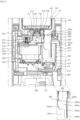
- FIG. 4 is an enlarged view of portion A in FIG. 3 .
- the humidifier may include a supply pipe 230 supplying water, stored in the water tank 100, to the first humidification water tank 300.
- the humidifier may include the first humidification water tank 300 heating the water, the second humidification water tank 350 (or "humidification water tank") generating humidified air using a vibrator 370, the humidification module housing 410 defining a space in which the first humidification water tank 300 and the second humidification water tank 350 are disposed, and the middle tray 200 disposed at an upper side of the humidification module housing 410.
- the humidifier may not have the first humidification water tank 300.
- the humidifier may include a humidification module for heating water and generating humidified air.
- the first humidification water tank 300 and the second humidification water tank 350 may be included in the humidification module.
- the humidification module may not include the first humidification water tank 300.
- the humidifier may include the supply pipe 230 supplying the water, stored in the water tank 100, to the first humidification water tank 300.
- the supply pipe 230 may be disposed between the water tank 100 and the first humidification water tank 300.
- the supply pipe 230 may temporarily store the water discharged from the water tank 100 and supplied to the first humidification water tank 300.
- the humidifier may include the humidification module housing 410 defining a space in which the first humidification water tank 300 and the second humidification water tank 350 are disposed.
- the display 30 may be disposed on one side of the humidification module housing 410.
- the middle tray 200 may be disposed at an upper side of the humidification module housing 410.
- a supply chamber 232 in which water is temporarily stored, may be formed in the supply pipe 230.
- a sensor 234 for detecting the hardness of water stored therein may be disposed on one side of the supply pipe 230.
- An upper end of the supply pipe 230 may protrude above the middle tray 200.
- the upper end of the supply pipe 230 may pass through a first hole 204 formed in the middle tray 200, and may be connected to the inner water tank 102 disposed at an upper side thereof.
- the middle tray 200 is disposed under the inner shell 180.
- the first hole 204 may be formed at the center of a tray plate 202.
- the second hole 208 may be disposed at a position radially spaced apart from the first hole 204.
- the humidifier may include the display 30 disposed on one side of the humidification module housing 410.
- the humidifier may include a first connection pipe 390 connecting the first humidification water tank 300 and the second humidification water tank 350, and a second connection pipe (not shown).
- the first connection pipe 390 may supply water, heated by the first humidification water tank 300, to the second humidification water tank 350.
- a second valve (not shown) for opening and closing the first connection pipe 390 may be disposed in the first connection pipe 390.
- a pump (not shown) for supplying water stored in the second humidification water tank 350 to the first humidification water tank 300 may be disposed in the second connection pipe.
- the first humidification water tank 300 and the second humidification water tank 350 may be connected to each other by a communication pipe 310 disposed above the first connection pipe 390.
- a first humidification water tank wall 302 may have a cylindrical shape in which water is stored.
- the first humidification water tank wall 302 has an open bottom, and a heater 340 may be disposed at a lower side of the first humidification water tank 302.
- the first humidification water tank 300 may include top covers 322 and 326 disposed at the top of the first humidification water tank wall 302.
- the top covers 322 and 326 may be disposed at the top of an upper water tank wall 304.
- the top covers 322 and 326 may be disposed to cover at least a portion of the top of the first humidification water tank wall 302.
- the top covers 322 and 326 may include a first top cover 322 and a second top cover 326 disposed under the first top cover 322.
- a communication flow path 311 for allowing the first humidification water tank 300 and the second humidification water tank 350 to communicate with each other may be formed in the communication pipe 310.
- the humidified air, generated in the first humidification water tank 300 and flowing upward, may flow to the second humidification water tank 350 through the communication flow path 311.
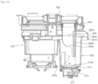
- the second humidification water tank 350 includes a second humidification water tank wall 352 defining a space in which water is stored, and the vibrator 370 disposed at a lower side of the second humidification water tank wall 352 and vibrates to atomize water in the second humidification water tank wall 352.
- the vibrator 370 may include a vibration device 372 for generating vibration, and a vibrator cover 371 defining a space in which the vibration device 372 is disposed and covering the top of the vibration device 372, and a vibration plate 374 (see FIG. 13 ) disposed on one side of the vibrator cover 371 and configured to vibrate by the operation of the vibration device 372.
- the vibrator 370 may include a vibration plate fixing member 375 (see FIG. 12 ) disposed at a lower side of the vibrator cover 371 and fixing the position of the vibration plate 374.
- the humidifier may include two vibration devices 372 and two vibration plates 374. Accordingly, each of the two vibration plates 374 vibrates to vibrate water present in the second chamber 350a.
- the vibrator 370 may include a first vibration plate 374a, and a second vibration plate 374b spaced apart from the first vibration plate 374a.
- the first vibration plate 374a may be disposed under a first lower extension wall 384a which will be described below, and the second vibration plate 374b may be disposed under a second lower extension wall 384b which will be described below.
- Two vibration plates 374 may be disposed on a lower surface of the second humidification water tank wall 352.
- the two vibration plates 374 may be spaced apart from each other in a direction perpendicular to the up-down direction.
- the second humidification water tank 350 includes a humidification water tank cover 380 (see FIG. 5 ) disposed at or connected to an upper side of the second humidification water tank wall 352.
- the humidification water tank cover 380 may supply the humidified air, generated in the second humidification water tank wall 352, to the first discharge flow path 32.
- the second humidification water tank wall 352 may form the second chamber 350a (or "chamber") in which water is stored.
- the humidification water tank wall 352 may have a pillar shape that is open at the top and bottom.
- the humidification water tank wall 352 may have a structure in which a cross-section area thereof increases from the bottom to the top.
- the humidification water tank cover 380 includes an air discharge pipe 382 allowing the humidified air to flow upward.
- the air discharge pipe 382 may extend upward form the humidification water tank cover 380.
- the air discharge pipe 382 may have a substantially oval pillar shape.
- An upper end of the air discharge pipe 382 may make contact with the middle tray 200.
- the upper end of the air discharge pipe 382 may directly contact the middle tray 200 or may indirectly contact the middle tray 200 through a separate sealer 388.
- the air discharge pipe 382 may be disposed under the middle tray 200.
- the air discharge pipe 382 may be disposed under the inner shell 180.
- the sealer 388 is disposed between the air discharge pipe 382 and the middle tray 200.
- the sealer 388 is disposed between the air discharge pipe 382 and the inner shell 180.
- the sealer 388 may be disposed between the air discharge pipe 382 and the middle tray 200 and/or the inner shell 180.
- the sealer 388 may prevent water, moving upward by the vibrator 370 disposed in the second humidification water tank 350, from flowing between the air discharge pipe 382 and the middle tray 200. In addition, the sealer 388 may prevent water, moving upward by the vibrator 370 disposed in the second humidification water tank 350, from flowing between air discharge pipe 382 and the inner shell 180.
- the sealer 388 may prevent the condensate water from flowing between the air discharge pipe 382 and the inner shell 180.
- An air discharge pipe inlet 382a (or air discharge hole) is formed at a lower end of the air discharge pipe 382.
- An air discharge pipe outlet 382b is formed at an upper end of the air discharge pipe 382.
- the air discharge pipe 382 may have an air discharge pipe channel 383 formed between the air discharge pipe inlet 382a and the air discharge pipe outlet 382b.
- An air supply hole 387 is formed at one side of the humidification water tank cover 380. External air may be introduced into the second humidification water tank wall 352 through the air supply hole 387.
- the air supply hole 387 may have a shape which is open at the top.
- the humidification water tank cover 380 includes an air guide cover 386 supplying air, flowing through the air flow path 70, to the second humidification water tank wall 352.
- the air guide cover 386 guides a portion of air, flowing outside of the humidification module housing 410, to flow into the second humidification water tank wall 352 through the air supply hole 387.
- An air guide rib 412 that switches a rotational flow of air, which flows along the humidification module housing 410, to an up flow may be disposed at a lower side of the air guide cover 386.
- the air guide cover 386 may extend outward of a peripheral surface of the humidification module housing 410. Accordingly, the air guide cover 386 may guide a portion of the air, flowing upward along the air flow path 70, to flow to the second humidification water tank wall 352.
- a lower extension wall 384 is disposed between an air discharge hole 382a and the air supply hole 387.
- the lower extension wall 384 may have a shape that is bent toward the air discharge hole 382a when viewed from above. Accordingly, air introduced into the second humidification water tank wall 352 through the air supply hole 387 may flow along a lower portion and an inner peripheral surface of the second humidification water tank wall 352.
- the lower extension wall 384 may extend downward between the air discharge hole 382a and the air supply hole 387.
- the lower extension wall 384 may allow the air, introduced into the second humidification water tank wall 352 through the air supply hole 387, to flow toward the lower portion of the second humidification water tank wall 352.
- the humidifier includes a water drain pipe 394 that drains water remaining in the first humidification water tank 300, and a water drain pipe valve 396 for opening and closing the water drain pipe 394.
- the water drain pipe 394 may be connected to one side of the first humidification water tank 300.
- the water drain pipe valve 396 may be disposed at an end of the water drain pipe 394.
- the humidification water tank cover 380 may be disposed at or connected to the top of the second humidification water tank wall 352.
- the humidification water tank cover 380 may cover the top of the second humidification water tank wall 352.
- the air discharge hole 382a, through which the humidified air generated in the second chamber 350a is discharged, is formed in the humidification water tank cover 380.
- the air discharge pipe 382, protruding upward from the humidification water tank cover 380 and having the air discharge pipe channel 383 formed therein, may be disposed in the humidification water tank cover 380.
- the humidification water tank cover 380 may include an air guide cover 386 extending in one direction from a region where the air discharge pipe 382 is formed.
- the humidification water tank cover 380 may include the lower extension wall 384 extending downward from the humidification water tank cover 380.
- the humidification water tank cover 380 may include a first top cover 322 disposed at or connected to the top of the first humidification water tank wall 302. That is, the first top cover 322 and the humidification water tank cover 380 may be integrally formed with each other.
- the humidification water tank cover 380 may form an upper part of the first humidification water tank 300 and the second humidification water tank 350.
- the air discharge pipe 382 has a structure that extends upward from the humidification water tank cover 380.
- the air discharge pipe 382 may extend upward from a circumference surface of the air discharge hole 382a or from a position adjacent to the circumference surface.
- the air discharge pipe 382 may allow the first discharge flow path 32 and the second chamber 350a to communicate with each other.
- the air discharge pipe 382 may supply the humidified air, generated in the second humidification water tank 350, to the first discharge flow path 32.
- the air discharge pipe 382 may supply the humidified air, generated in the first humidification water tank 300 or the second humidification water tank 350, to the first discharge flow path 32.
- the air discharge pipe 382 may supply condensate water, generated in the first discharge flow path 32, to the inside of the second humidification water tank 350.
- the air discharge hole 382a is formed in the humidification water tank cover 380.
- the air discharge pipe 382 may extend upward directly from a circumferential surface of the air discharge hole 382a or from a position adjacent to the circumferential surface.
- the air discharge hole 382a may form the inlet of the air discharge pipe channel 383.
- the air guide cover 386 may guide a portion of air, flowing outside of the humidification module housing 410, to flow into the second humidification water tank 350 through the air supply hole 387a.
- the air guide cover 386 may guide air, flowing outside of the second humidification water tank 350, to flow into the second humidification water tank 350.
- the air guide cover 386 may be upwardly spaced apart from the air supply hole 387a and may extend horizontally from the air discharge pipe 382.
- the air guide cover 386 may extend from a circumferential wall of the air discharge pipe 382 and may be disposed at a position spaced above an upper end of the second humidification water tank wall 352.
- the air guide cover 386 may extend outward of a peripheral surface of the humidification module housing 410 (see FIG. 4 ). Accordingly, the air guide cover 386 may guide a portion of air, flowing upward along the air flow path 70 (see FIG. 4 ), to flow into the second humidification water tank 350.
- the lower extension wall 384 may extend downward from the humidification water tank cover 380, preferably from one side of a circumference surface of the air discharge hole 382a.
- the lower extension wall 384 may extend downward from the humidification water tank cover 380 in a region where the air discharge pipe 382 is formed.
- the lower extension wall 384 may extend downward from the air discharge pipe 382 in a region where the air guide cover 386 is disposed.
- the lower extension wall 384 may guide air, flowing into the second humidification water tank 350 through the air guide cover 386, to flow downward.
- the lower extension wall 384 may extend downward in the region where the air supply hole 387a is formed.
- the lower extension wall 384 may include a first lower extension wall 384a, and a second lower extension wall 384b spaced apart from the first lower extension wall 384a.
- a slit 385a may be formed between the first lower extension wall 384a and the second lower extension wall 384b.
- the lower extension wall 384 may include a lower connection wall 385b disposed above the slit 385a and connecting the first lower extension wall 384a and the second lower extension wall 384b.
- the lower extension wall 384 may be formed along the air discharge hole 382a. Accordingly, when viewed from above or below, the lower extension wall 384 may have a curved surface extending along the air discharge hole 382a.
- the first lower extension wall 384a and the second lower extension wall 384b may have the same length in the vertical direction. However, a length L1 of the first lower extension wall 384a, which extends in a direction (circumferential direction) that is perpendicular to a vertical or up-down direction, may be different from a length L2 of the second lower extension wall 384b which extends in a direction (circumferential direction) that is perpendicular to the vertical direction.
- the length of the first lower extension wall 384a, which extends in the circumferential direction of the air discharge hole 382a, may be shorter than the length of the second lower extension wall 384b that extends in the circumferential direction of the air discharge hole 382a.
- the slit 385a may be formed to extend upward from a lower end of the first lower extension wall 384a and the second lower extension wall 384b. Referring to FIG. 8 , a vertical length 385ah of the slit 385a may be half or more of a vertical length 384h of the first lower extension wall 384a or the second lower extension wall 384b.
- the slit 385a has a width 385aw that decreases from the bottom to the top thereof.
- the lower extension wall 384 may include a first additional extension wall 384a1 disposed on one side of the first lower extension wall 384a, and a second additional extension wall 384b1 disposed on one side of the second lower extension wall 384b.
- the first additional extension wall 384a1 and the second additional extension wall 384b1 may also extend downward from the circumference surface of the air discharge hole 382a.
- the first additional extension wall 384a1 has a shape in which the vertical length thereof decreases away from the first lower extension wall 384a.
- the second additional extension wall 384b1 has a shape in which the vertical length thereof decreases away from the second lower extension wall 384b.
- the first additional extension wall 384a1 and the second additional extension wall 384b1 may be spaced apart from each other.
- the first additional extension wall 384a1 and the second additional extension wall 384b1 may be spaced apart from each other so that air, flowing through the communication pipe 310, may flow to the air discharge hole 382a.
- a length L3 of the first additional extension wall 384a1, which extends in a direction perpendicular to the vertical direction, may be different from a length L4 of the second additional extension wall 384b1, which extends in a direction perpendicular to the vertical direction.
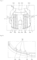
- the lower extension wall 384 may include an inner rib 389 which protrudes from an inner surface of the lower extension wall 384 and extends in the vertical direction.
- the inner rib 389 may guide movement of water that falls down along the air discharge pipe 382.
- the inner rib 389 may guide movement of water that falls down along the lower extension wall 384.
- a plurality of inner ribs 389 may be formed on the lower extension wall 384.
- the plurality of inner ribs 389 may be arranged at regular intervals in a circumferential direction of the air discharge hole.
- the plurality of inner ribs 389 may be divided into a plurality of first inner ribs 389a which are disposed on the first lower extension wall 384a, and a plurality of second inner ribs 389b which are disposed on the second lower extension wall 384b.
- a length 389h of the inner rib 389 that protrudes from the lower extension wall 384 may be longer than a thickness 384t of the lower extension wall 384.
- the plurality of first inner ribs 389a arranged on the first lower extension wall 384a may be equally spaced apart from each other.
- the plurality of second inner ribs 389b formed on the second lower extension wall 384b may be equally spaced apart from each other.
- the plurality of inner ribs 389 may also be arranged at different intervals.
- the number of first inner ribs 389a arranged on the first lower extension wall 384a may be equal to the number of second inner ribs 389b arranged on the second lower extension wall 384b.
- the number of second inner ribs 389b arranged on the second lower extension wall 384b may be greater than the number of first inner ribs 389a arranged on the first lower extension wall 384a.
- a lower groove 383b which is recessed in a radially outward direction of the air discharge pipe 382, may be formed in a lower portion of the air discharge pipe 382.
- the lower groove 383b may be disposed at one side of a circumferential surface of the air discharge pipe 382.
- the lower groove 383b may be disposed above the lower extension wall 384.
- the lower groove 383b may be disposed above the inner ribs 389.
- the lower groove 383b may be disposed above the both of the first lower extension wall 384a and the second lower extension wall 384b.
- the lower groove 383b may temporarily reduce the speed of water flowing downward along the circumference of the air discharge pipe 382.
- the water, flowing into the second humidification water tank wall 352 along the lower extension wall 384, may flow after temporarily stagnating in the lower groove 383b.
- Two vibration plates 374 are disposed at a lower side where the air discharge hole 382a is formed.
- a first vibration plate 374a and a second vibration plate 374b may be disposed at the lower side where the air discharge hole 382a is formed.
- the two vibration plates 374 and the air discharge hole 382a may at least partially overlap with each other in the vertical direction.
- the air discharge hole 382a may have a substantially oval shape.
- the air discharge hole 382a may have a shape modified from an exact oval shape.
- a radius of curvature of a portion of the air discharge hole 382a, which is disposed far from the first humidification water tank 300, may be greater than a radius of curvature of another portion of the air discharge hole 382a which is disposed close to the first humidification water tank 300.
- the vibration plate 374 may be disposed adjacent to the lower extension wall 384. That is, by dividing the air discharge hole 382a into a first region AR1, in which the lower extension wall 384 is disposed, and a second region AR2 facing the first region AR1 in which the lower extension wall 384 is disposed, the vibration plate 374 may be disposed closer to the first region AR1 than the second region AR2.
- the first vibration plate 374a is disposed below a region in which the first inner ribs 389a are formed, and the second vibration plate 374b is disposed below a region in which the second inner ribs 389b are formed.
- the plurality of inner ribs 389 may protrude from the lower extension wall 384 on a circumferential surface where the vibration plate 374 is disposed.
- the plurality of first inner ribs 3 89a protrude from the first lower extension wall 384a on the circumferential surface where the first vibrator 374a is disposed.
- the plurality of second inner ribs 389b protrude from the second lower extension wall 384b on the circumferential surface where the second vibrator 374b is disposed.
- the vibrator 370 includes a vibration device 372 configured to receive power to generate vibration, a vibration plate 374 configured to atomize water in the second chamber 350a by using vibration transmitted from the vibration device 372, and a vibrator cover 371 defining a space in which the vibration device 372 is disposed and covering the top of the vibration device 372.
- the vibrator 370 may include a vibration plate fixing member 375 for fixing the position of the vibration plate 374.
- the vibrator 370 includes a first vibration plate 374a, and a second vibration plate 374b spaced apart from the first vibration plate 374a.
- a first cover hole 371a which is open at the top of the first vibration plate 374a, and a second cover hole 371b, which is open at the top of the second vibration plate 374b, may be formed in the vibrator cover 371.
- the vibration plates 374a and 374b may be disposed below the cover holes 371a and 371b, respectively.
- the vibration plate 374 may be formed in a shape in which an upper surface thereof is inclined toward the lower extension wall 384.
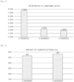
- the vibration plate 374 may form an inclination angle of from 3° to 5° with respect to a plane horizontal to the ground. As the vibration plate 374 forms the inclination angle, a proportion of abnormal noise generated due to the operation of the vibrator 370 may be improved. As the vibration plate 374 forms the inclination angle, water scattered upward due to the vibration of the vibrator 374 may flow toward the lower extension wall 384, thereby improving noise caused by falling water which is generated in the second chamber 350a.
- a proportion of abnormal noise generated due to the operation of the vibrator 370 is 7 % or more, but in case where the inclination angle of the vibration plate 374 is in a range of 3° to 5°, the proportion of abnormal noise is improved to 3 % or less. Particularly, in case where an inclination angle of the vibration plate is 5 degrees, the proportion of abnormal noise generated due to the operation of the vibrator 370 is improved to 2 % or less.
- the vibration plate 374 is inclined within an inclination angle range of 5 degrees, humidification performance is not reduced compared to the case where an inclination angle of the vibration plate 374 is 0 degrees.
- the vibration plate 374 is inclined at an inclination angle of 5 degrees, a humidification amount rather increases compared to the case where an inclination angle of the vibration plate 374 is 0 degrees.
- the inclination may refer to an angle at which the vibration plate 374 is inclined with respect to an imaginary horizontal line.
- the number of inner ribs 389 formed on the first lower extension wall 384a and the second lower extension wall 384b may vary.
- the number of inner ribs 389 formed on each of the first lower extension wall 384a and the second lower extension wall 384b may vary depending on the length of the first lower extension wall 384a and the second lower extension wall 384a that extends in a circumferential direction.
- the inner ribs 389, formed on each of the first lower extension wall 384a and the second lower extension wall 384a, may be two or more in number.
- first inner ribs 389a may be formed on the first lower extension wall 384a, and four second inner ribs 389b may be formed on the second lower extension wall 384b.
- two first inner ribs 389a may be formed on the first lower extension wall 384a, and three second inner ribs 389b may be formed on the second lower extension wall 384b.
- a distance D1 between the first inner rib 389a, disposed adjacent to the slit 385a, among the plurality of first inner ribs 389a, and the slit 385a may be equal to or smaller than a distance D2 between the plurality of first inner ribs 389a.
- a distance D3 between the second inner rib 389b, disposed adjacent to the slit 385a, among the plurality of second inner ribs 389b, and the slit 385a may be equal to or smaller than a distance D4 between the plurality of second inner ribs 389b.
- FIG. 18 is a diagram illustrating data about abnormal noise generated during operation of each of the first vibrator 370 or the second vibrator 370.
- the lengths of the first lower extension wall 384a and the second lower extension wall 384b, which extend circumferentially, are different from each other, and air introduced through the air guide cover 386 does not flow at a constant speed, such that a magnitude of noise generated due to the operation of the first vibrator 370 may be different from a magnitude of noise generated due to the operation of the second vibrator 370.
- noise in structure B according to the embodiment of FIG. 9 is significantly reduced, compared to a structure in which the first lower extension wall 384a and the second lower extension wall 384b are not included.
- noise in arrangement B of the inner ribs 389 according to the embodiment of FIG. 9 is reduced by 60 % or more, compared to the structure including no inner ribs.
- noise is reduced by 20 % or more.
Landscapes
- Engineering & Computer Science (AREA)
- Chemical & Material Sciences (AREA)
- Combustion & Propulsion (AREA)
- Mechanical Engineering (AREA)
- General Engineering & Computer Science (AREA)
- Dispersion Chemistry (AREA)
- Air Humidification (AREA)
Abstract
The present disclosure relates to a humidifier.
The humidifier according to the present disclosure includes a water tank storing water, and a humidification water tank receiving water from the water tank to generate humidified air, wherein the humidification water tank includes: a humidification water tank wall having a chamber in which water is stored; a vibrator disposed at a lower side of the humidification water tank wall and having a vibration plate configured to vibrate the water stored in the chamber; a humidification water tank cover disposed at an upper side of the humidification water tank wall, and having an air discharge hole through which the humidified air generated in the chamber is discharged; and a lower extension wall extending downward from the humidification water tank cover on at least one side of a circumference of the air discharge hole, wherein an upper surface of the vibration plate is inclined from an upper side toward the lower extension wall.
Description
- The present disclosure relates to a humidifier, and more particularly, to a humidifier for generating humidified air by using sterilized water.
- A humidifier is a device for vaporizing water to discharge humidified air with high moisture content. The humidifier may generate humidified air by evaporating water using natural vaporization, heating vaporization, and ultrasonic vibration.
- Each evaporation method has its merits and demerits. The evaporative humidification method has a drawback in that a user is required to frequently clean a humidifying medium after use.
- The heating vaporization has a problem in that if hot humidified air is directly discharged, a safety accident may occur.
- Vaporization using ultrasonic vibration has problems in that air, humidified by atomizing supplied water by ultrasonic vibration, may not effectively flow into an indoor space, and if unsterilized water is used for humidification, unpleasant humid air may flow into the indoor space, and an ultrasonic vibrator is vulnerable to high-temperature heat.
- In addition, vaporization by ultrasonic vibration has a problem in that water may be splashed or scattered upward due to vibration generated by the vibrator. Noise may occur when the scattered water falls down.
- Korean Patent No. KR 10- 0158806 discloses a humidifier for humidifying water, supplied from a water tank, by heating and ultrasonic vibration. Even in this structure, noise may occur when water scattered by the ultrasonic vibrator falls down.
- It is an objective of the present disclosure to provide a humidifier capable of minimizing noise caused by water scattered when generating humidified air using an ultrasonic vibrator.
- It is another objective of the present disclosure to provide a humidifier capable of guiding movement of water that falls into a chamber.
- It is yet another objective of the present disclosure to provide a humidifier capable of reducing a moving speed of water that falls into a chamber.
- It is yet another objective of the present disclosure to provide a humidifier capable of ensuring the amount of humidified air generated in a humidification water tank and discharged therefrom.
- It is yet another objective of the present disclosure to provide a humidifier capable of minimizing noise caused by water scattered in a humidification water tank, while controlling a flow of air supplied to a humidification water tank.
- The objectives of the present disclosure are not limited to the aforementioned objectives and other objectives not described herein will be clearly understood by those skilled in the art from the following description.
- In order to achieve the above objectives, a humidifier according to an embodiment of the present disclosure includes: a water tank storing water; and a humidification water tank receiving water from the water tank to generate humidified air, such that the humidifier generates humidified air by using water supplied from the water tank. The humidification water tank includes: a humidification water tank wall extending substantially in a vertical direction and surrounding a chamber in which water is stored; a vibrator disposed at a lower side of the humidification water tank wall and having a vibration plate configured to vibrate the water stored in the chamber; a humidification water tank cover disposed at an upper side of the humidification water tank wall, and having an air discharge hole through which the humidified air generated in the chamber is discharged; and a lower extension wall extending downward from the humidification water tank cover. The vibration plate is inclined with respect to a horizontal plane in the manner that an upper surface of the vibration plate faces a side surface of the lower extension wall. This structure allows water, vibrated by the vibration plate, to be scattered toward the lower extension wall. The lower extension wall may have an end disposed on or adjacent to a circumference of the air discharge hole.
- An inclination angle formed between the side surface of the lower extension wall and the upper surface of the vibration plate may be an acute angle, such that the vibration plate may be inclined toward the lower extension wall.
- The vibration plate may be inclined at an inclination angle of from 3° to 5° with respect to an imaginary horizontal line parallel to a ground plane, thereby allowing water to be scattered toward the lower extension wall.
- The circumference surface of the air discharge hole may include a first region and a second region spaced apart from the first region. The first region may be disposed closer to the lower extension wall than the second region. The vibration plate may be disposed horizontally closer to the first region than the second region, thereby allowing water, scattered by the vibration plate, to rapidly reach the lower extension wall.
- The vibration plate may be disposed below the air discharge hole, such that humidified air, generated by the vibration plate, may flow toward the air discharge hole.
- The vibration plate may include a first vibration plate, and a second vibration plate spaced apart from the first vibration plate in a first direction, wherein the lower extension wall may include a first lower extension wall, and a second lower extension wall spaced apart from the first lower extension wall in the first direction, such that water scattered from each of the two vibration plates may move to the two lower extension walls, respectively.
- The first lower extension wall may be disposed in a direction facing the first vibration plate, and the second lower extension wall may be disposed in a direction facing the second vibration plate, such that water scattered from each of the two vibration plates may move to the two lower extension walls, respectively. In other words, the first lower extension wall may be disposed in the manner that a side surface of the first lower extension wall faces an upper surface of the first vibration plate, and the second lower extension wall may be disposed in the manner that a side surface of the second lower extension wall faces an upper surface of the second vibration plate.
- A slit may be formed between the first lower extension wall and the second lower extension wall. The slit may extend in a second direction perpendicular to the first direction.
- The lower extension wall may further include an additional extension wall that extends in a direction away from each of the first lower extension wall and the second lower extension wall, thereby covering a wide range of water scattered by the vibration plate.
- A plurality of inner ribs are formed on the lower extension wall, the plurality of inner ribs protruding in an inward direction of the air discharge hole and extending vertically, thereby guiding the water, scattered toward the lower extension wall, in a downward direction.
- The plurality of inner ribs may be disposed to face the upper surface of the vibration plate, thereby guiding the water, scattered toward the lower extension wall, in a downward direction.
- A length of each of the plurality of inner ribs protruding from the lower extension wall may be greater than a width of the lower extension wall.
- The humidifier may further include an inner shell defining a space in which the water tank is disposed, and having a discharge flow path at a position spaced apart from the water tank, wherein the humidification water tank cover may include an air discharge pipe which extends upward to allow the humidified air, generated in the humidification water tank, to flow upward, and is connected to a lower end of the inner shell, such that the humidified air generated in the chamber may be discharged in a space between the water tank and the inner shell.
- A lower groove may be formed in a lower portion of the air discharge pipe, the lower groove recessed radially outward from an inner surface of the air discharge pipe, thereby reducing a moving speed of condensate water or scattered water that flows along the air discharge pipe.
- The lower groove may be disposed upward from the lower extension wall.
- A humidifier according to the present disclosure includes: a first humidification water tank having a first chamber for heating water; a second humidification water tank connected to the first humidification water tank and having a second chamber for generating humidified air using a vibrator and water supplied from the first humidification water tank; a fan disposed at a lower side of the second humidification water tank and configured to generate an air flow; and a connection pipe supplying water, stored in the first humidification water tank, to the second humidification water tank, thereby generating humidified air by using water sterilized by heating. The second humidification water tank may include: an air discharge hole through which the humidified air generated in the second chamber is discharged outside, and an air supply hole through which air blown by the fan is supplied to the second chamber; a lower extension wall disposed between the air discharge hole and the air supply hole, and extending downward from an upper part of the second humidification water tank; and a vibrator disposed on a lower surface of the second humidification water tank, and having a vibration plate disposed below the air discharge hole and configured to vibrate water stored in the second chamber. The vibration plate may be disposed closer to the air discharge hole than the air supply hole with respect to the lower extension wall. The vibration plate may be inclined in the manner that an upper surface of the vibration plate faces a side surface of the lower extension wall. This structure allows the water supplied to the humidification water tank to be cooled by air flowing through the air supply pipe. This structure also allows the water scattered by the vibration plate to move to the lower extension wall, thereby reducing noise caused by falling water.
- The vibration plate may include a first vibration plate, and a second vibration plate spaced apart from the first vibration plate in a first direction, and the lower extension wall may include a first lower extension wall, and a second lower extension wall spaced apart from the first lower extension wall in the first direction. A slit may be formed between the first lower extension wall and the second lower extension wall. The slit may be open in a second direction perpendicular to the first direction, thereby ensuring an air flow through the slit, and guiding movement of scattered water through the lower extension wall.
- A vertical length of the slit may be half or more of a vertical length of the first lower extension wall or the second lower extension wall.
- A humidifier according to the present disclosure includes: a humidification water tank wall having a chamber in which water is stored; a vibrator disposed at a lower side of the humidification water tank wall and having a vibration plate configured to vibrate the water stored in the chamber; a humidification water tank cover disposed at an upper side of the humidification water tank wall, and having an air discharge hole through which the humidified air generated in the chamber is discharged; an air discharge pipe extending upward from the humidification water tank cover, and having an air discharge pipe channel in which the humidified air flows; and a lower extension wall extending downward from the humidification water tank cover on at least one side of the circumference of the air discharge hole, thereby allowing the humidified air generated in the chamber to be discharged through the air discharge pipe. The air discharge pipe may extend from the circumference of the air discharge hole or a position adjacent to the air discharge hole. In addition, a lower groove may be formed in a lower portion of the air discharge pipe. The lower groove may be recessed radially outward from an inner circumferential surface of the air discharge pipe, such that while condensate water falling to the air discharge pipe or scattered water scattered by the vibrator flows downward along the air discharge pipe, a flow speed of the water may be reduced by the lower groove.
- An upper surface of the vibration plate may be inclined from an upper side toward the lower extension wall, thereby allowing the scattered water to flow toward the lower extension wall and the air discharge pipe.
- Other detailed matters of the exemplary embodiments are included in the detailed description and the drawings.
- A humidifier according to the present disclosure has one or more of the following effects.
- First, water scattered by a vibrator is concentrated on a lower extension wall side, thereby minimizing noise caused by water that falls after scattering.
- Second, water scattered to inner ribs formed on a lower extension wall is not diffused, but flows downward along the inner ribs, thereby reducing the amount of scattered water that causes noise and reducing a scattering range of water, such that noise may be reduced.
- Third, a lower groove is formed at a lower side of an air discharge pipe, which buffers falling of water that falls down along the air discharge pipe, thereby allowing the water to move to the chamber at a slower speed, and reducing noise caused by the falling water.
- Fourth, a vibrator is disposed at a lower side of an air discharge hole, such that most of the humidified air, generated by vibration of a vibration plate, may flow through the air discharge hole. Accordingly, most of the generated humid air may flow through the air discharge hole, thereby ensuring an amount of humidification.
- Fifth, a lower extension wall is disposed between an air supply hole and an air discharge hole, such that generated humid air may be rapidly discharged through the air discharge hole along with air introduced through the air supply hole.
- The effects of the present disclosure are not limited to the aforesaid, and other effects not described herein will be clearly understood by those skilled in the art from the following description of the appended claims.
-
-
FIG. 1 is a perspective view of a humidifier according to an embodiment of the present disclosure. -
FIG. 2 is a plan view ofFIG. 1 . -
FIG. 3 is a cross-sectional view taken along line III-III' ofFIG. 2 . -
FIG. 4 is an enlarged view of portion IV inFIG. 3 . -
FIG. 5 is a perspective view of a humidification water tank cover according to an embodiment of the present disclosure. -
FIG. 6 is a side view ofFIG. 5 . -
FIG. 7 is another side view ofFIG. 5 . -
FIG. 8 is a front view ofFIG. 5 . -
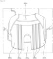
FIG. 9 is an enlarged bottom perspective view of a portion of a humidification water tank cover according to an embodiment of the present disclosure. -
FIG. 10 is a diagram explaining the arrangement and size of a lower extension wall and an inner protrusion according to an embodiment of the present disclosure. -
FIG. 11 is a partial plan view of a second humidification water tank cover according to an embodiment of the present disclosure. -
FIG. 12 is a cross-sectional view of a first humidification water tank and a second humidification water tank, as taken along line X II-X II' ofFIG. 11 . -
FIG. 13 is a cross-sectional view of a second humidification water tank, as taken along line X III-X III' ofFIG. 11 . -
FIG. 14 is a diagram illustrating data about a proportion of abnormal noise generated in a humidifier with respect to inclination of a vibrator plate, according to an embodiment of the present disclosure. -
FIG. 15 is a diagram illustrating data about an amount of humidified air, generated and discharged by a humidifier, with respect to inclination of a vibrator plate, according to an embodiment of the present disclosure. -
FIG. 16 is an enlarged bottom perspective view of a portion of a humidification water tank cover according to another embodiment of the present disclosure. -
FIG. 17 is an enlarged bottom perspective view of a portion of a humidification water tank cover according to yet another embodiment of the present disclosure. -
FIG. 18 is a diagram illustrating data about proportion of measured noise in the case where no inner rib is formed on a lower extension wall and in the case where different numbers of inner ribs are formed on the lower extension wall. - Advantages and features of the present disclosure and methods for achieving the same become apparent from the embodiments described below in conjunction with the accompanying drawings. However, the present disclosure is not limited to the embodiments described below, and may be embodied in various forms. The embodiments are provided merely to make the present invention fully disclosed and to completely inform those skilled in the art of the category of the invention. The present invention is defined by the appended claims. The same reference numerals refer to the same parts throughout the specification.
- Hereinafter, a humidifier of the present invention will be described with reference to embodiments disclosed in the following description and drawings.
- First, the overall configuration of a humidifier will be described below with reference to
FIGS. 1 to 3 . - The humidifier may atomize water by ultrasonic vibration to generate humidified air. The humidifier may heat water to discharge humidified air. The humidifier may discharge the humidified air generated by ultrasonic vibration and the humidified air generated by heating.
- Referring to
FIGS. 1 to 3 , the humidifier includes: acase 10 forming an outer appearance thereof and having aninlet 24a and anoutlet 12a; a filter device disposed inside thecase 10 and configured to filter air introduced through theinlet 24a; a blower device 60 disposed inside thecase 10 and configured to cause air in thecase 10 to flow from theinlet 24a to theoutlet 12a; awater tank 100 disposed inside thecase 10 and storing water; and a humidification module configured to generate humidified air by receiving water from thewater tank 100. - The humidifier may include the
water tank 100 disposed inside thecase 10 and temporarily storing water and supplying the stored water to the humidification module, aninner shell 180 defining a space in which thewater tank 100 is disposed, and amiddle tray 200 disposed under theinner shell 180. - The humidification module may include a first
humidification water tank 300 for heating water and a secondhumidification water tank 350 for generating humidified air using water. Alternatively, the humidification module may include only the secondhumidification water tank 350. The humidification module may include ahumidification module housing 410 that covers the periphery of the humidification module. Aflow path housing 430 may be formed on an outer periphery of thehumidification module housing 410. Anair flow path 70 may be formed between thehumidification module housing 410 and theflow path housing 430. The configuration and arrangement of the humidification module will be described below in detail. - The
case 10 may have a substantially cylindrical shape. - The
case 10 may include asuction grill 24 having theinlet 24a through which air is introduced, and adischarge grill 12 having theoutlet 12a through which air is discharged. - The
inlet 24a may be formed on a circumferential surface of thecase 10 having a cylindrical shape. Theoutlet 12a may be formed on an upper surface of thecase 10 having a cylindrical shape. The humidifier according to the present disclosure may introduce air through the circumferential surface of thecase 10 and may discharge air through the upper surface thereof. - Referring to
FIG. 3 , thesuction grill 24 may cover the outside of ablower housing 68 and afilter 50 which will be described below. Thesuction grill 24 may have a plurality ofinlets 24a which are vertically formed and are circumferentially spaced apart from each other. Theinlets 24a may be formed around a portion where thefilter 50 is disposed. Theinlets 24a may be formed at a lower portion of thesuction grill 24. Theinlets 24a are formed at the lower portion of thesuction grill 24, and an upper portion of thesuction grill 24 may be closed in order to protect the internal components of the humidifier. - A plurality of
grills 24b which vertically extend may be formed on thesuction grill 24. The plurality ofgrills 24b may be spaced apart from each other in a circumferential direction of thesuction grill 24. The plurality ofinlets 24a may be formed between the plurality ofgrills 24b. - The
suction grill 24 may be divided into alower suction grill 25a having theinlets 24a and anupper suction grill 25b disposed above thelower suction grill 25a. Adisplay 30 which will be described below may be disposed on theupper suction grill 25b. Theupper suction grill 25b may cover theblower housing 68 and the outside of the humidification module which will be described below. - The humidifier may include the
discharge grill 12 having theoutlet 12a and a water tank cover 14 disposed at an upper side of thewater tank 100. Thedischarge grill 12 may have a structure which is separated upward from anouter shell 22 which will be described below. Thewater tank cover 14 may have a structure which is separated from thedischarge grill 12 or thewater tank 100. Thedischarge grill 12 may include a plurality ofribs 12b radially extending from an outer periphery of thewater tank cover 14. The plurality ofribs 12b which are disposed on thedischarge grill 12 may be circumferentially spaced apart from the outer periphery of thewater tank cover 14. - Referring to
FIG. 2 , thewater tank cover 14 may include acenter cover 16 and acircumference cover 18 disposed around the circumference of thecenter cover 16. Thecenter cover 16 may be upwardly convex toward the center. Awater supply hole 20, through which water flows into thewater tank 100, may be formed between thecircumference cover 18 and thecenter cover 16. - Referring to
FIG. 1 , thedischarge grill 12 may be disposed at an upper side of a firstdischarge flow path 32 and at an upper side of a seconddischarge flow path 34 which will be described below. The plurality ofribs 12b and the plurality ofoutlets 12a may be formed on thedischarge grill 12. - The
discharge grill 12 may have a constant height in a vertical or up-down direction. Accordingly, a mixingflow path 13 may be formed between the plurality ofribs 12b disposed on thedischarge grill 12. Air flowing through the firstdischarge flow path 32 may be mixed with air flowing through the seconddischarge flow path 34. - Each of the plurality of
ribs 12b may be formed so that an outer circumferential end has a greater height than an inner circumferential end. Accordingly, it is possible to guide air, flowing through the firstdischarge flow path 32 and the seconddischarge flow path 34, to flow radially inwardly. - The
case 10 may include theouter shell 22 for guiding air, flowing inside thecase 10, to theoutlet 12a. Theouter shell 22 may form the seconddischarge flow path 34 along with theinner shell 180 which will be described below. - The
outer shell 22 may include an upperouter shell 22a disposed under thedischarge grill 12 and a lowerouter shell 22b disposed under the upperouter shell 22a. The lowerouter shell 22b may be made of a transparent material. - The
case 10 may include abottom wall 26 covering the lower side of thesuction grill 24. - The humidifier may include a
pedestal 28 disposed under thecase 10 and allowing thebottom wall 26 to be spaced above the ground by a predetermined distance. An upper end of thepedestal 28 may be connected to thebottom wall 26. Thebottom wall 26 covers a bottom surface of the humidifier which is spaced above the ground by thepedestal 28. - Referring to
FIG. 2 , thedisplay 30 is disposed on one side of thecase 10. Thedisplay 30 may allow a user to control power or operation of the humidifier. Thedisplay 30 may include a display for displaying an operating state and the like of the humidifier for a user. - In the filter device, air introduced through the
inlet 24a is filtered through thefilter 50. The filter device may allow the filtered air to flow upward. - Referring to
FIG. 3 , the filter device includes thefilter 50 for filtering the air introduced through theinlet 24a, and a filter mounting part disposed inside thecase 10 and fixing the position of thefilter 50. - The
filter 50 may have a circular pillar shape. Accordingly, thefilter 50 may filter air drawn in from the front, rear, left and/or right directions perpendicular to an up-down direction. The air introduced through theinlet 24a may flow into an internal space of thefilter 50. After passing through thefilter 50, the air may flow to the blower device 60 disposed at an upper side of thefilter 50. - The filter mounting part may include a
lower plate 52 disposed at a lower side of thefilter 50, anupper plate 54 disposed at an upper side of thefilter 50, and a supporter (not shown) connecting thelower plate 52 and theupper plate 54. - The
lower plate 52 is disposed at the lower side of thefilter 50. Thelower plate 52 may move up and down and may detect whether thefilter 50 is mounted. Afan sterilizer 53 for emitting ultraviolet light in an upward direction may be disposed at the center of thelower plate 52. Thefan sterilizer 53 may sterilize the inside of thefan 62 or thefilter 50 which will be described below. - An
orifice 56 is formed in theupper plate 54. Theorifice 56 may be formed at the center of theupper plate 54. Theorifice 56 may allow the air, flowing into thefilter 50, to flow to thefan 62. An inner peripheral edge of theupper plate 54 may have an upwardly bent shape, thereby guiding the air, which flows upward from the internal space of thefilter 50, to flow to thefan 62. - The supporter 58 may connect the
lower plate 52 and theupper plate 54. The supporter 58 may be circumferentially spaced apart from each other. - The blower device 60 includes the
fan 62 for generating an air flow in thecase 10 and afan motor 64 for rotating thefan 62. - Referring to
FIG. 3 , thefan 62 has a fan inlet formed on one side facing theorifice 56, and a fan outlet formed in an opposite direction of the fan inlet. Thefan 62 may be a mixed flow fan having a fan outlet formed toward a centrifugal direction in the opposite direction of the fan inlet. Thefan 62 may include a hub connected to thefan motor 64, a shroud spaced apart from the hub by a predetermined distance and forming the fan inlet, and a blade radially extending to connect the hub and the shroud. - The
fan 62 may operate to cause air at a lower side of the case to flow upward. Thefan 62 draws in air through theorifice 56, and discharges air through theblower housing 68 where thediffuser 72 is disposed. - The
fan motor 64 may be disposed at an upper side of thefan 62. - The blower device includes a
motor cover 66 covering the outside of thefan motor 64, and theblower housing 68 radially outwardly spaced apart from themotor cover 66 and guiding the air, blown by thefan 62, to flow upward. - The
air flow path 70, through which the air blown by thefan 62 flows upward, may be formed between themotor cover 66 and theblower housing 68. Theair flow path 70 may extend up to a region where thehumidification module housing 410 and theflow path housing 430 are formed. - The
suction grill 24 may be disposed outside theblower housing 68. - The blower device 60 includes a
diffuser 72 disposed between themotor cover 66 and theblower housing 68, and reducing the rotational component of air blown by thefan 62 to flow upward. A plurality ofdiffusers 72 may be circumferentially spaced apart from each other. - A
control box 74 defining a space in which acircuit board 76 is disposed, may be disposed at an upper side of themotor cover 66. Thecontrol box 74 may be spaced apart inwardly of theblower housing 68. Accordingly, theair flow path 70 may also be formed between thecontrol box 74 and theblower housing 68. - A plurality of
circuit boards 76 may be disposed in thecontrol box 74. - The
water tank 100 may include aninner water tank 102 and an outer water tank 160. Thewater tank 100 may be formed such that theinner water tank 102 is disposed inside the outer water tank 160. - While being disposed inside the
inner shell 180, the outer water tank 160 may be disposed at an upper side of themiddle tray 200. Themiddle tray 200 may support theinner shell 180, the outer water tank 160, and theinner water tank 102. Accordingly, load of theinner water tank 102, the outer water tank 160, and theinner shell 180 may be transmitted to themiddle tray 200. - The outer water tank 160 is disposed on an outer periphery of the
inner water tank 102. - A through hole 164 is formed in a lower surface of the outer water tank 160, and a portion of the connector 120 may be disposed at a lower side of the outer water tank 160 through the through hole 164.
- The
inner shell 180 may define a space in which thewater tank 100 is disposed. - A shell penetration hole 184 is formed in a lower surface of the
inner shell 180. The shell penetration hole 184 is disposed at a lower side of the through hole 164 of the outer water tank 160. The connector 120 may be disposed in the shell penetration hole 184. - An air discharge connection pipe 192, through which the humidified air discharged from the humidification module flows, is disposed on a lower surface of the
inner shell 180. An air discharge connection pipe hole 194 is formed inside the air discharge connection pipe 192. -
FIG. 4 is an enlarged view of portion A inFIG. 3 . - The configuration related to the humidification module will be described below with reference to
FIG. 4 . - The humidifier may include a
supply pipe 230 supplying water, stored in thewater tank 100, to the firsthumidification water tank 300. The humidifier may include the firsthumidification water tank 300 heating the water, the second humidification water tank 350 (or "humidification water tank") generating humidified air using avibrator 370, thehumidification module housing 410 defining a space in which the firsthumidification water tank 300 and the secondhumidification water tank 350 are disposed, and themiddle tray 200 disposed at an upper side of thehumidification module housing 410. Alternatively, the humidifier may not have the firsthumidification water tank 300. - The humidifier may include a humidification module for heating water and generating humidified air. The first
humidification water tank 300 and the secondhumidification water tank 350 may be included in the humidification module. The humidification module may not include the firsthumidification water tank 300. - The humidifier may include the
supply pipe 230 supplying the water, stored in thewater tank 100, to the firsthumidification water tank 300. Thesupply pipe 230 may be disposed between thewater tank 100 and the firsthumidification water tank 300. Thesupply pipe 230 may temporarily store the water discharged from thewater tank 100 and supplied to the firsthumidification water tank 300. - The humidifier may include the
humidification module housing 410 defining a space in which the firsthumidification water tank 300 and the secondhumidification water tank 350 are disposed. Thedisplay 30 may be disposed on one side of thehumidification module housing 410. Themiddle tray 200 may be disposed at an upper side of thehumidification module housing 410. - A
supply chamber 232, in which water is temporarily stored, may be formed in thesupply pipe 230. Asensor 234 for detecting the hardness of water stored therein may be disposed on one side of thesupply pipe 230. - An upper end of the
supply pipe 230 may protrude above themiddle tray 200. The upper end of thesupply pipe 230 may pass through afirst hole 204 formed in themiddle tray 200, and may be connected to theinner water tank 102 disposed at an upper side thereof. - The
middle tray 200 is disposed under theinner shell 180. Thefirst hole 204, through which thesupply pipe 230 passes, is formed in themiddle tray 200. Thefirst hole 204 may be formed at the center of a tray plate 202. - A
second hole 208, through which the humidified air discharged from the secondhumidification water tank 350 flows, is formed in themiddle tray 200. Thesecond hole 208 may be disposed at a position radially spaced apart from thefirst hole 204. - The humidifier may include the
display 30 disposed on one side of thehumidification module housing 410. - The humidifier may include a
first connection pipe 390 connecting the firsthumidification water tank 300 and the secondhumidification water tank 350, and a second connection pipe (not shown). Thefirst connection pipe 390 may supply water, heated by the firsthumidification water tank 300, to the secondhumidification water tank 350. A second valve (not shown) for opening and closing thefirst connection pipe 390 may be disposed in thefirst connection pipe 390. A pump (not shown) for supplying water stored in the secondhumidification water tank 350 to the firsthumidification water tank 300 may be disposed in the second connection pipe. - The first
humidification water tank 300 and the secondhumidification water tank 350 may be connected to each other by acommunication pipe 310 disposed above thefirst connection pipe 390. - A first humidification
water tank wall 302 may have a cylindrical shape in which water is stored. The first humidificationwater tank wall 302 has an open bottom, and aheater 340 may be disposed at a lower side of the firsthumidification water tank 302. - The first
humidification water tank 300 may includetop covers water tank wall 302. The top covers 322 and 326 may be disposed at the top of an upper water tank wall 304. - The top covers 322 and 326 may be disposed to cover at least a portion of the top of the first humidification
water tank wall 302. The top covers 322 and 326 may include a firsttop cover 322 and a secondtop cover 326 disposed under the firsttop cover 322. - A
communication flow path 311 for allowing the firsthumidification water tank 300 and the secondhumidification water tank 350 to communicate with each other may be formed in thecommunication pipe 310. The humidified air, generated in the firsthumidification water tank 300 and flowing upward, may flow to the secondhumidification water tank 350 through thecommunication flow path 311. - The second
humidification water tank 350 includes a second humidificationwater tank wall 352 defining a space in which water is stored, and thevibrator 370 disposed at a lower side of the second humidificationwater tank wall 352 and vibrates to atomize water in the second humidificationwater tank wall 352. - The
vibrator 370 may include avibration device 372 for generating vibration, and avibrator cover 371 defining a space in which thevibration device 372 is disposed and covering the top of thevibration device 372, and a vibration plate 374 (seeFIG. 13 ) disposed on one side of thevibrator cover 371 and configured to vibrate by the operation of thevibration device 372. - The
vibrator 370 may include a vibration plate fixing member 375 (seeFIG. 12 ) disposed at a lower side of thevibrator cover 371 and fixing the position of thevibration plate 374. - Referring to
FIG. 13 , the humidifier may include twovibration devices 372 and twovibration plates 374. Accordingly, each of the twovibration plates 374 vibrates to vibrate water present in thesecond chamber 350a. Thevibrator 370 may include afirst vibration plate 374a, and asecond vibration plate 374b spaced apart from thefirst vibration plate 374a. - Referring to
FIG. 13 , thefirst vibration plate 374a may be disposed under a firstlower extension wall 384a which will be described below, and thesecond vibration plate 374b may be disposed under a secondlower extension wall 384b which will be described below. - Two
vibration plates 374 may be disposed on a lower surface of the second humidificationwater tank wall 352. The twovibration plates 374 may be spaced apart from each other in a direction perpendicular to the up-down direction. - The second
humidification water tank 350 includes a humidification water tank cover 380 (seeFIG. 5 ) disposed at or connected to an upper side of the second humidificationwater tank wall 352. The humidificationwater tank cover 380 may supply the humidified air, generated in the second humidificationwater tank wall 352, to the firstdischarge flow path 32. - The second humidification
water tank wall 352 may form thesecond chamber 350a (or "chamber") in which water is stored. The humidificationwater tank wall 352 may have a pillar shape that is open at the top and bottom. The humidificationwater tank wall 352 may have a structure in which a cross-section area thereof increases from the bottom to the top. - The humidification
water tank cover 380 includes anair discharge pipe 382 allowing the humidified air to flow upward. Theair discharge pipe 382 may extend upward form the humidificationwater tank cover 380. Theair discharge pipe 382 may have a substantially oval pillar shape. - An upper end of the
air discharge pipe 382 may make contact with themiddle tray 200. Here, the upper end of theair discharge pipe 382 may directly contact themiddle tray 200 or may indirectly contact themiddle tray 200 through aseparate sealer 388. - The
air discharge pipe 382 may be disposed under themiddle tray 200. Theair discharge pipe 382 may be disposed under theinner shell 180. - The
sealer 388 is disposed between theair discharge pipe 382 and themiddle tray 200. Thesealer 388 is disposed between theair discharge pipe 382 and theinner shell 180. Thesealer 388 may be disposed between theair discharge pipe 382 and themiddle tray 200 and/or theinner shell 180. - The
sealer 388 may prevent water, moving upward by thevibrator 370 disposed in the secondhumidification water tank 350, from flowing between theair discharge pipe 382 and themiddle tray 200. In addition, thesealer 388 may prevent water, moving upward by thevibrator 370 disposed in the secondhumidification water tank 350, from flowing betweenair discharge pipe 382 and theinner shell 180. - When condensate water generated in the
inner shell 180 flows downward, thesealer 388 may prevent the condensate water from flowing between theair discharge pipe 382 and theinner shell 180. - An air
discharge pipe inlet 382a (or air discharge hole) is formed at a lower end of theair discharge pipe 382. An airdischarge pipe outlet 382b is formed at an upper end of theair discharge pipe 382. Theair discharge pipe 382 may have an airdischarge pipe channel 383 formed between the airdischarge pipe inlet 382a and the airdischarge pipe outlet 382b. - An
air supply hole 387 is formed at one side of the humidificationwater tank cover 380. External air may be introduced into the second humidificationwater tank wall 352 through theair supply hole 387. Theair supply hole 387 may have a shape which is open at the top. - The humidification
water tank cover 380 includes anair guide cover 386 supplying air, flowing through theair flow path 70, to the second humidificationwater tank wall 352. Theair guide cover 386 guides a portion of air, flowing outside of thehumidification module housing 410, to flow into the second humidificationwater tank wall 352 through theair supply hole 387. - An
air guide rib 412 that switches a rotational flow of air, which flows along thehumidification module housing 410, to an up flow may be disposed at a lower side of theair guide cover 386. - The
air guide cover 386 may extend outward of a peripheral surface of thehumidification module housing 410. Accordingly, theair guide cover 386 may guide a portion of the air, flowing upward along theair flow path 70, to flow to the second humidificationwater tank wall 352. - A
lower extension wall 384 is disposed between anair discharge hole 382a and theair supply hole 387. Thelower extension wall 384 may have a shape that is bent toward theair discharge hole 382a when viewed from above. Accordingly, air introduced into the second humidificationwater tank wall 352 through theair supply hole 387 may flow along a lower portion and an inner peripheral surface of the second humidificationwater tank wall 352. - The
lower extension wall 384 may extend downward between theair discharge hole 382a and theair supply hole 387. Thelower extension wall 384 may allow the air, introduced into the second humidificationwater tank wall 352 through theair supply hole 387, to flow toward the lower portion of the second humidificationwater tank wall 352. - The humidifier includes a
water drain pipe 394 that drains water remaining in the firsthumidification water tank 300, and a waterdrain pipe valve 396 for opening and closing thewater drain pipe 394. Thewater drain pipe 394 may be connected to one side of the firsthumidification water tank 300. The waterdrain pipe valve 396 may be disposed at an end of thewater drain pipe 394. - Hereinafter, the shape of the humidification water tank cover, the air discharge pipe, and the lower extension wall will be described with reference to
FIGS. 5 to 10 . - The humidification
water tank cover 380 may be disposed at or connected to the top of the second humidificationwater tank wall 352. The humidificationwater tank cover 380 may cover the top of the second humidificationwater tank wall 352. Theair discharge hole 382a, through which the humidified air generated in thesecond chamber 350a is discharged, is formed in the humidificationwater tank cover 380. - The
air discharge pipe 382, protruding upward from the humidificationwater tank cover 380 and having the airdischarge pipe channel 383 formed therein, may be disposed in the humidificationwater tank cover 380. The humidificationwater tank cover 380 may include anair guide cover 386 extending in one direction from a region where theair discharge pipe 382 is formed. The humidificationwater tank cover 380 may include thelower extension wall 384 extending downward from the humidificationwater tank cover 380. - The humidification
water tank cover 380 may include a firsttop cover 322 disposed at or connected to the top of the first humidificationwater tank wall 302. That is, the firsttop cover 322 and the humidificationwater tank cover 380 may be integrally formed with each other. - The humidification
water tank cover 380 may form an upper part of the firsthumidification water tank 300 and the secondhumidification water tank 350. - The
air discharge pipe 382 has a structure that extends upward from the humidificationwater tank cover 380. Theair discharge pipe 382 may extend upward from a circumference surface of theair discharge hole 382a or from a position adjacent to the circumference surface. Theair discharge pipe 382 may allow the firstdischarge flow path 32 and thesecond chamber 350a to communicate with each other. Theair discharge pipe 382 may supply the humidified air, generated in the secondhumidification water tank 350, to the firstdischarge flow path 32. Theair discharge pipe 382 may supply the humidified air, generated in the firsthumidification water tank 300 or the secondhumidification water tank 350, to the firstdischarge flow path 32. - The
air discharge pipe 382 may supply condensate water, generated in the firstdischarge flow path 32, to the inside of the secondhumidification water tank 350. - The
air discharge hole 382a is formed in the humidificationwater tank cover 380. Theair discharge pipe 382 may extend upward directly from a circumferential surface of theair discharge hole 382a or from a position adjacent to the circumferential surface. Theair discharge hole 382a may form the inlet of the airdischarge pipe channel 383. - The
air guide cover 386 may guide a portion of air, flowing outside of thehumidification module housing 410, to flow into the secondhumidification water tank 350 through theair supply hole 387a. - The
air guide cover 386 may guide air, flowing outside of the secondhumidification water tank 350, to flow into the secondhumidification water tank 350. - The
air guide cover 386 may be upwardly spaced apart from theair supply hole 387a and may extend horizontally from theair discharge pipe 382. Theair guide cover 386 may extend from a circumferential wall of theair discharge pipe 382 and may be disposed at a position spaced above an upper end of the second humidificationwater tank wall 352. - The
air guide cover 386 may extend outward of a peripheral surface of the humidification module housing 410 (seeFIG. 4 ). Accordingly, theair guide cover 386 may guide a portion of air, flowing upward along the air flow path 70 (seeFIG. 4 ), to flow into the secondhumidification water tank 350. - The
lower extension wall 384 may extend downward from the humidificationwater tank cover 380, preferably from one side of a circumference surface of theair discharge hole 382a. Thelower extension wall 384 may extend downward from the humidificationwater tank cover 380 in a region where theair discharge pipe 382 is formed. Thelower extension wall 384 may extend downward from theair discharge pipe 382 in a region where theair guide cover 386 is disposed. - The
lower extension wall 384 may guide air, flowing into the secondhumidification water tank 350 through theair guide cover 386, to flow downward. Thelower extension wall 384 may extend downward in the region where theair supply hole 387a is formed. - The
lower extension wall 384 may include a firstlower extension wall 384a, and a secondlower extension wall 384b spaced apart from the firstlower extension wall 384a. Aslit 385a may be formed between the firstlower extension wall 384a and the secondlower extension wall 384b. Thelower extension wall 384 may include alower connection wall 385b disposed above theslit 385a and connecting the firstlower extension wall 384a and the secondlower extension wall 384b. - The
lower extension wall 384 may be formed along theair discharge hole 382a. Accordingly, when viewed from above or below, thelower extension wall 384 may have a curved surface extending along theair discharge hole 382a. - The first
lower extension wall 384a and the secondlower extension wall 384b may have the same length in the vertical direction. However, a length L1 of the firstlower extension wall 384a, which extends in a direction (circumferential direction) that is perpendicular to a vertical or up-down direction, may be different from a length L2 of the secondlower extension wall 384b which extends in a direction (circumferential direction) that is perpendicular to the vertical direction. - The length of the first
lower extension wall 384a, which extends in the circumferential direction of theair discharge hole 382a, may be shorter than the length of the secondlower extension wall 384b that extends in the circumferential direction of theair discharge hole 382a. - The
slit 385a may be formed to extend upward from a lower end of the firstlower extension wall 384a and the secondlower extension wall 384b. Referring toFIG. 8 , a vertical length 385ah of theslit 385a may be half or more of avertical length 384h of the firstlower extension wall 384a or the secondlower extension wall 384b. - The
slit 385a has a width 385aw that decreases from the bottom to the top thereof. - The
lower extension wall 384 may include a first additional extension wall 384a1 disposed on one side of the firstlower extension wall 384a, and a second additional extension wall 384b1 disposed on one side of the secondlower extension wall 384b. - The first additional extension wall 384a1 and the second additional extension wall 384b1 may also extend downward from the circumference surface of the
air discharge hole 382a. - The first additional extension wall 384a1 has a shape in which the vertical length thereof decreases away from the first
lower extension wall 384a. The second additional extension wall 384b1 has a shape in which the vertical length thereof decreases away from the secondlower extension wall 384b. - The first additional extension wall 384a1 and the second additional extension wall 384b1 may be spaced apart from each other. The first additional extension wall 384a1 and the second additional extension wall 384b1 may be spaced apart from each other so that air, flowing through the
communication pipe 310, may flow to theair discharge hole 382a. - A length L3 of the first additional extension wall 384a1, which extends in a direction perpendicular to the vertical direction, may be different from a length L4 of the second additional extension wall 384b1, which extends in a direction perpendicular to the vertical direction.
- The
lower extension wall 384 may include aninner rib 389 which protrudes from an inner surface of thelower extension wall 384 and extends in the vertical direction. Theinner rib 389 may guide movement of water that falls down along theair discharge pipe 382. Theinner rib 389 may guide movement of water that falls down along thelower extension wall 384. - A plurality of
inner ribs 389 may be formed on thelower extension wall 384. The plurality ofinner ribs 389 may be arranged at regular intervals in a circumferential direction of the air discharge hole. - The plurality of
inner ribs 389 may be divided into a plurality of firstinner ribs 389a which are disposed on the firstlower extension wall 384a, and a plurality of secondinner ribs 389b which are disposed on the secondlower extension wall 384b. - Referring to
FIG. 10 , alength 389h of theinner rib 389 that protrudes from thelower extension wall 384 may be longer than athickness 384t of thelower extension wall 384. Referring toFIG. 10 , the plurality of firstinner ribs 389a arranged on the firstlower extension wall 384a may be equally spaced apart from each other. Likewise, the plurality of secondinner ribs 389b formed on the secondlower extension wall 384b may be equally spaced apart from each other. - However, the plurality of
inner ribs 389 may also be arranged at different intervals. Referring toFIG. 9 , the number of firstinner ribs 389a arranged on the firstlower extension wall 384a may be equal to the number of secondinner ribs 389b arranged on the secondlower extension wall 384b. - However, unlike the drawing, the number of second
inner ribs 389b arranged on the secondlower extension wall 384b may be greater than the number of firstinner ribs 389a arranged on the firstlower extension wall 384a. - A
lower groove 383b, which is recessed in a radially outward direction of theair discharge pipe 382, may be formed in a lower portion of theair discharge pipe 382. Thelower groove 383b may be disposed at one side of a circumferential surface of theair discharge pipe 382. Thelower groove 383b may be disposed above thelower extension wall 384. Thelower groove 383b may be disposed above theinner ribs 389. Thelower groove 383b may be disposed above the both of the firstlower extension wall 384a and the secondlower extension wall 384b. - The
lower groove 383b may temporarily reduce the speed of water flowing downward along the circumference of theair discharge pipe 382. The water, flowing into the second humidificationwater tank wall 352 along thelower extension wall 384, may flow after temporarily stagnating in thelower groove 383b. - Hereinafter, the shape of the
air discharge hole 382a, formed in the humidificationwater tank cover 380, and the arrangement of a vibrator will be described with reference toFIG. 11 . - Two
vibration plates 374 are disposed at a lower side where theair discharge hole 382a is formed. Afirst vibration plate 374a and asecond vibration plate 374b may be disposed at the lower side where theair discharge hole 382a is formed. In other words, the twovibration plates 374 and theair discharge hole 382a may at least partially overlap with each other in the vertical direction. - The
air discharge hole 382a may have a substantially oval shape. Theair discharge hole 382a may have a shape modified from an exact oval shape. A radius of curvature of a portion of theair discharge hole 382a, which is disposed far from the firsthumidification water tank 300, may be greater than a radius of curvature of another portion of theair discharge hole 382a which is disposed close to the firsthumidification water tank 300. - The
vibration plate 374 may be disposed adjacent to thelower extension wall 384. That is, by dividing theair discharge hole 382a into a first region AR1, in which thelower extension wall 384 is disposed, and a second region AR2 facing the first region AR1 in which thelower extension wall 384 is disposed, thevibration plate 374 may be disposed closer to the first region AR1 than the second region AR2. - The
first vibration plate 374a is disposed below a region in which the firstinner ribs 389a are formed, and thesecond vibration plate 374b is disposed below a region in which the secondinner ribs 389b are formed. - The plurality of
inner ribs 389 may protrude from thelower extension wall 384 on a circumferential surface where thevibration plate 374 is disposed. - The plurality of first
inner ribs 3 89a protrude from the firstlower extension wall 384a on the circumferential surface where thefirst vibrator 374a is disposed. The plurality of secondinner ribs 389b protrude from the secondlower extension wall 384b on the circumferential surface where thesecond vibrator 374b is disposed. - Hereinafter, the arrangement of a vibration plate and the structure of a lower extension wall and an air discharge pipe will be described with reference to
FIGS. 12 and13 . - The
vibrator 370 includes avibration device 372 configured to receive power to generate vibration, avibration plate 374 configured to atomize water in thesecond chamber 350a by using vibration transmitted from thevibration device 372, and avibrator cover 371 defining a space in which thevibration device 372 is disposed and covering the top of thevibration device 372. Thevibrator 370 may include a vibrationplate fixing member 375 for fixing the position of thevibration plate 374. - Referring to
FIG. 13 , thevibrator 370 includes afirst vibration plate 374a, and asecond vibration plate 374b spaced apart from thefirst vibration plate 374a. - A
first cover hole 371a, which is open at the top of thefirst vibration plate 374a, and asecond cover hole 371b, which is open at the top of thesecond vibration plate 374b, may be formed in thevibrator cover 371. - The
vibration plates cover holes vibration plate 374 may be formed in a shape in which an upper surface thereof is inclined toward thelower extension wall 384. - The
vibration plate 374 may form an inclination angle of from 3° to 5° with respect to a plane horizontal to the ground. As thevibration plate 374 forms the inclination angle, a proportion of abnormal noise generated due to the operation of thevibrator 370 may be improved. As thevibration plate 374 forms the inclination angle, water scattered upward due to the vibration of thevibrator 374 may flow toward thelower extension wall 384, thereby improving noise caused by falling water which is generated in thesecond chamber 350a. - According to
FIG. 14 , in case where an inclination angle of thevibration plate 374 is 0 degrees, a proportion of abnormal noise generated due to the operation of thevibrator 370 is 7 % or more, but in case where the inclination angle of thevibration plate 374 is in a range of 3° to 5°, the proportion of abnormal noise is improved to 3 % or less. Particularly, in case where an inclination angle of the vibration plate is 5 degrees, the proportion of abnormal noise generated due to the operation of thevibrator 370 is improved to 2 % or less. - In addition, according to
FIG. 15 , even when thevibration plate 374 is inclined within an inclination angle range of 5 degrees, humidification performance is not reduced compared to the case where an inclination angle of thevibration plate 374 is 0 degrees. According toFIG. 15 , in case where thevibration plate 374 is inclined at an inclination angle of 5 degrees, a humidification amount rather increases compared to the case where an inclination angle of thevibration plate 374 is 0 degrees. Here, the inclination may refer to an angle at which thevibration plate 374 is inclined with respect to an imaginary horizontal line. - Referring to
FIGS. 16 and17 , the number ofinner ribs 389 formed on the firstlower extension wall 384a and the secondlower extension wall 384b may vary. Referring toFIG. 16 , the number ofinner ribs 389 formed on each of the firstlower extension wall 384a and the secondlower extension wall 384b may vary depending on the length of the firstlower extension wall 384a and the secondlower extension wall 384a that extends in a circumferential direction. - The
inner ribs 389, formed on each of the firstlower extension wall 384a and the secondlower extension wall 384a, may be two or more in number. - Referring to
FIG. 16 , three firstinner ribs 389a may be formed on the firstlower extension wall 384a, and four secondinner ribs 389b may be formed on the secondlower extension wall 384b. Referring toFIG. 17 , two firstinner ribs 389a may be formed on the firstlower extension wall 384a, and three secondinner ribs 389b may be formed on the secondlower extension wall 384b. - A distance D1 between the first
inner rib 389a, disposed adjacent to theslit 385a, among the plurality of firstinner ribs 389a, and theslit 385a may be equal to or smaller than a distance D2 between the plurality of firstinner ribs 389a. Likewise, a distance D3 between the secondinner rib 389b, disposed adjacent to theslit 385a, among the plurality of secondinner ribs 389b, and theslit 385a may be equal to or smaller than a distance D4 between the plurality of secondinner ribs 389b. -
FIG. 18 is a diagram illustrating data about abnormal noise generated during operation of each of thefirst vibrator 370 or thesecond vibrator 370. The lengths of the firstlower extension wall 384a and the secondlower extension wall 384b, which extend circumferentially, are different from each other, and air introduced through theair guide cover 386 does not flow at a constant speed, such that a magnitude of noise generated due to the operation of thefirst vibrator 370 may be different from a magnitude of noise generated due to the operation of thesecond vibrator 370. - According to
FIG. 18 , noise in structure B according to the embodiment ofFIG. 9 is significantly reduced, compared to a structure in which the firstlower extension wall 384a and the secondlower extension wall 384b are not included. - Further, noise in arrangement B of the
inner ribs 389 according to the embodiment ofFIG. 9 is reduced by 60 % or more, compared to the structure including no inner ribs. - In addition, as illustrated in
FIG. 16 , even in structure A in which three firstinner ribs 389a and four secondinner ribs 389b are disposed, noise is reduced by 20 % or more. - As illustrated in
FIG. 17 , even in structure C in which two firstinner ribs 389a and three secondinner ribs 389b are disposed, noise is reduced by 20 % or more. - While the preferred embodiments have been particularly shown and described, the present specification shall not be limited to the particular embodiments described above, and it will be understood by an ordinary skilled person in the art that various changes in form and details may be made therein without departing from the spirit and scope of the present invention as defined by the following claims, and the alternative embodiments should not be individually understood from the inventive concept and prospect of the present disclosure.
Claims (15)
- A humidifier comprising:a water tank (100) for storing water; anda humidification water tank (350) for receiving water from the water tank (100) to generate humidified air,wherein the humidification water tank (350) comprises:a humidification water tank wall (352) extending substantially in a vertical direction and surrounding a chamber in which water is stored;a vibrator (370) disposed at a lower side of the humidification water tank wall (352) and having a vibration plate (374) configured to vibrate the water stored in the chamber;a humidification water tank cover (380) disposed at an upper side of the humidification water tank wall (352), and having an air discharge hole (382a) through which the humidified air generated in the chamber is discharged; anda lower extension wall (384) extending downward from the humidification water tank cover (380),wherein the vibration plate (374) is inclined with respect to a horizontal plane in the manner that an upper surface of the vibration plate (374) faces a side surface of the lower extension wall (384).
- The humidifier of claim 1, wherein the lower extension wall (384) has an end disposed on or adjacent to a circumference of the air discharge hole (382a).
- The humidifier of claim 1 or 2, wherein an inclination angle formed between the side surface of the lower extension wall (384) and the upper surface of the vibration plate (374) is an acute angle.
- The humidifier of any one of claims 1 to 3, wherein the vibration plate (374) is inclined at an inclination angle of from 3° to 5° with respect to the horizontal plane.
- The humidifier of claim 1, wherein a circumferential inner surface of the air discharge hole (382a) comprises a first region (AR1) and a second region (AR2) spaced apart from the first region (AR1); the first region (AR1) is disposed closer to the lower extension wall (384) than the second region (AR2); and the vibration plate (374) is disposed horizontally closer to the first region (AR1) than the second region (AR2).
- The humidifier of any one of claims 1 to 5, wherein the vibration plate (374) comprises a first vibration plate (374a), and a second vibration plate (374b) spaced apart from the first vibration plate (374a) in a first direction,
wherein the lower extension wall (384) comprises a first lower extension wall (384a), and a second lower extension wall (384b) spaced apart from the first lower extension wall (384a) in the first direction. - The humidifier of claim 6, wherein the first lower extension wall (384a) is disposed in the manner that a side surface of the first lower extension wall (384a) faces an upper surface of the first vibration plate (374a), and the second lower extension wall (384b) is disposed in the manner that a side surface of the second lower extension wall (384b) faces an upper surface of the second vibration plate (374b).
- The humidifier of claim 6 or 7, wherein a slit (385a) is formed between the first lower extension wall (384a) and the second lower extension wall (384b), and the slit (385a) extends in a second direction perpendicular to the first direction.
- The humidifier of any one of claims 6 to 8, wherein the lower extension wall (384) further comprises an additional extension wall (384a1) that extends in a direction away from each of the first lower extension wall (384a) and the second lower extension wall (384b).
- The humidifier of any one of claims 1 to 9, wherein a plurality of inner ribs (389) are formed on the lower extension wall (384), the plurality of inner ribs (389) protruding in an inward direction of the air discharge hole (382a) and extending vertically.
- The humidifier of claim 10, wherein the plurality of inner ribs (389) are disposed to face the upper surface of the vibration plate (374).
- The humidifier of claim 10 or 11, wherein a length of each of the plurality of inner ribs (389) protruding from the lower extension wall (384) is greater than a width of the lower extension wall (384).
- The humidifier of any one of claims 1 to 12, further comprising an inner shell (180) defining a space in which the water tank (100) is disposed, and having a discharge flow path (32) at a position spaced apart from the water tank (100),
wherein the humidification water tank cover (380) comprises an air discharge pipe (382) which extends upward to allow the humidified air, generated in the humidification water tank (350), to flow upward, and is connected to a lower end of the inner shell (180). - The humidifier of claim 13, wherein a lower groove (383b) is formed in a lower portion of the air discharge pipe (382), the lower groove (383b) recessed radially outward from an inner surface of the air discharge pipe (382).
- The humidifier of claim 14, wherein the lower groove (383b) is disposed upward from the lower extension wall (384).
Applications Claiming Priority (1)
| Application Number | Priority Date | Filing Date | Title |
|---|---|---|---|
| KR1020230079705A KR102809804B1 (en) | 2023-06-21 | 2023-06-21 | Humidifier |
Publications (1)
| Publication Number | Publication Date |
|---|---|
| EP4481286A1 true EP4481286A1 (en) | 2024-12-25 |
Family
ID=91616820
Family Applications (1)
| Application Number | Title | Priority Date | Filing Date |
|---|---|---|---|
| EP24183067.8A Pending EP4481286A1 (en) | 2023-06-21 | 2024-06-19 | Humidifier |
Country Status (4)
| Country | Link |
|---|---|
| US (1) | US20240426491A1 (en) |
| EP (1) | EP4481286A1 (en) |
| KR (1) | KR102809804B1 (en) |
| CN (1) | CN119178199A (en) |
Citations (4)
| Publication number | Priority date | Publication date | Assignee | Title |
|---|---|---|---|---|
| KR0158806B1 (en) | 1995-08-30 | 1999-01-15 | 배순훈 | Heating type ultrasonic humidifier |
| CN204757250U (en) * | 2015-06-26 | 2015-11-11 | 深圳市联创科技集团有限公司 | Ultrasonic humidifier with air-blowing channel air outlet provided with waterproof structure |
| WO2020052173A1 (en) * | 2018-09-13 | 2020-03-19 | 广东美的环境电器制造有限公司 | Humidifier and heater |
| JP2023007321A (en) * | 2021-06-30 | 2023-01-18 | 深▲セン▼市晨北科技有限公司 | humidifier |
Family Cites Families (6)
| Publication number | Priority date | Publication date | Assignee | Title |
|---|---|---|---|---|
| KR960024002U (en) * | 1994-12-06 | 1996-07-22 | Falling noise prevention device of ultrasonic humidifier | |
| KR0143844B1 (en) * | 1995-08-31 | 1998-08-01 | 배순훈 | Control circuit of ultrasonic heat humidifier |
| KR19980084036A (en) * | 1997-05-20 | 1998-12-05 | 윤종용 | Humidifier's fall noise prevention device |
| KR20170000509U (en) * | 2015-07-28 | 2017-02-07 | 한일전기 주식회사 | Ultrasonic humidifier |
| KR102602046B1 (en) * | 2021-09-17 | 2023-11-15 | 프롬비(주) | Dripping noise reducer and humidifier |
| CN114777244B (en) * | 2022-06-02 | 2026-02-03 | 佛山市顺德区巨科电器有限公司 | Clean sewage separation type fog-free humidifier |
-
2023
- 2023-06-21 KR KR1020230079705A patent/KR102809804B1/en active Active
-
2024
- 2024-06-19 EP EP24183067.8A patent/EP4481286A1/en active Pending
- 2024-06-19 CN CN202410791708.7A patent/CN119178199A/en active Pending
- 2024-06-20 US US18/748,268 patent/US20240426491A1/en active Pending
Patent Citations (4)
| Publication number | Priority date | Publication date | Assignee | Title |
|---|---|---|---|---|
| KR0158806B1 (en) | 1995-08-30 | 1999-01-15 | 배순훈 | Heating type ultrasonic humidifier |
| CN204757250U (en) * | 2015-06-26 | 2015-11-11 | 深圳市联创科技集团有限公司 | Ultrasonic humidifier with air-blowing channel air outlet provided with waterproof structure |
| WO2020052173A1 (en) * | 2018-09-13 | 2020-03-19 | 广东美的环境电器制造有限公司 | Humidifier and heater |
| JP2023007321A (en) * | 2021-06-30 | 2023-01-18 | 深▲セン▼市晨北科技有限公司 | humidifier |
Also Published As
| Publication number | Publication date |
|---|---|
| US20240426491A1 (en) | 2024-12-26 |
| CN119178199A (en) | 2024-12-24 |
| KR102809804B1 (en) | 2025-05-16 |
| KR20240178039A (en) | 2024-12-30 |
Similar Documents
| Publication | Publication Date | Title |
|---|---|---|
| US20240200801A1 (en) | Humidifier | |
| US20240200803A1 (en) | Humidifier | |
| KR20170051108A (en) | apparatus for both humidification and air cleaning | |
| KR20180070525A (en) | Air Cleaner | |
| US20240361021A1 (en) | Humidifier | |
| US20240200798A1 (en) | Humidifier | |
| KR101880484B1 (en) | apparatus for both humidification and air cleaning | |
| US20240200802A1 (en) | Humidifier | |
| EP4481286A1 (en) | Humidifier | |
| CN121474657A (en) | humidifier | |
| KR20210071373A (en) | apparatus for both humidification and air cleaning | |
| EP4455571A1 (en) | Humidifier | |
| KR20170107951A (en) | apparatus for both humidification and air cleaning | |
| KR20240095794A (en) | Humidifier | |
| US20260036314A1 (en) | Humidifier | |
| EP4692660A1 (en) | Humidifier | |
| KR102856634B1 (en) | Humidifier | |
| KR102802809B1 (en) | Humidifier | |
| KR102961755B1 (en) | Humidifier | |
| US20240361022A1 (en) | Humidifier | |
| EP4692659A1 (en) | Humidifier | |
| US20240361016A1 (en) | Humidifier | |
| KR20260044490A (en) | Humidifier | |
| CN118224676A (en) | humidifier | |
| KR20260044491A (en) | Humidifier |
Legal Events
| Date | Code | Title | Description |
|---|---|---|---|
| PUAI | Public reference made under article 153(3) epc to a published international application that has entered the european phase |
Free format text: ORIGINAL CODE: 0009012 |
|
| STAA | Information on the status of an ep patent application or granted ep patent |
Free format text: STATUS: REQUEST FOR EXAMINATION WAS MADE |
|
| 17P | Request for examination filed |
Effective date: 20240719 |
|
| AK | Designated contracting states |
Kind code of ref document: A1 Designated state(s): AL AT BE BG CH CY CZ DE DK EE ES FI FR GB GR HR HU IE IS IT LI LT LU LV MC ME MK MT NL NO PL PT RO RS SE SI SK SM TR |