EP4481261A1 - High pressure tank and method for producing the same - Google Patents
High pressure tank and method for producing the same Download PDFInfo
- Publication number
- EP4481261A1 EP4481261A1 EP23180003.8A EP23180003A EP4481261A1 EP 4481261 A1 EP4481261 A1 EP 4481261A1 EP 23180003 A EP23180003 A EP 23180003A EP 4481261 A1 EP4481261 A1 EP 4481261A1
- Authority
- EP
- European Patent Office
- Prior art keywords
- type
- dry fibres
- layer
- fibres
- winded
- Prior art date
- Legal status (The legal status is an assumption and is not a legal conclusion. Google has not performed a legal analysis and makes no representation as to the accuracy of the status listed.)
- Pending
Links
Images

Classifications
-
- F—MECHANICAL ENGINEERING; LIGHTING; HEATING; WEAPONS; BLASTING
- F17—STORING OR DISTRIBUTING GASES OR LIQUIDS
- F17C—VESSELS FOR CONTAINING OR STORING COMPRESSED, LIQUEFIED OR SOLIDIFIED GASES; FIXED-CAPACITY GAS-HOLDERS; FILLING VESSELS WITH, OR DISCHARGING FROM VESSELS, COMPRESSED, LIQUEFIED, OR SOLIDIFIED GASES
- F17C1/00—Pressure vessels, e.g. gas cylinder, gas tank, replaceable cartridge
- F17C1/02—Pressure vessels, e.g. gas cylinder, gas tank, replaceable cartridge involving reinforcing arrangements
- F17C1/04—Protecting sheathings
- F17C1/06—Protecting sheathings built-up from wound-on bands or filamentary material, e.g. wires
-
- F—MECHANICAL ENGINEERING; LIGHTING; HEATING; WEAPONS; BLASTING
- F17—STORING OR DISTRIBUTING GASES OR LIQUIDS
- F17C—VESSELS FOR CONTAINING OR STORING COMPRESSED, LIQUEFIED OR SOLIDIFIED GASES; FIXED-CAPACITY GAS-HOLDERS; FILLING VESSELS WITH, OR DISCHARGING FROM VESSELS, COMPRESSED, LIQUEFIED, OR SOLIDIFIED GASES
- F17C1/00—Pressure vessels, e.g. gas cylinder, gas tank, replaceable cartridge
- F17C1/16—Pressure vessels, e.g. gas cylinder, gas tank, replaceable cartridge constructed of plastics materials
-
- F—MECHANICAL ENGINEERING; LIGHTING; HEATING; WEAPONS; BLASTING
- F17—STORING OR DISTRIBUTING GASES OR LIQUIDS
- F17C—VESSELS FOR CONTAINING OR STORING COMPRESSED, LIQUEFIED OR SOLIDIFIED GASES; FIXED-CAPACITY GAS-HOLDERS; FILLING VESSELS WITH, OR DISCHARGING FROM VESSELS, COMPRESSED, LIQUEFIED, OR SOLIDIFIED GASES
- F17C2201/00—Vessel construction, in particular geometry, arrangement or size
- F17C2201/01—Shape
- F17C2201/0104—Shape cylindrical
- F17C2201/0109—Shape cylindrical with exteriorly curved end-piece
-
- F—MECHANICAL ENGINEERING; LIGHTING; HEATING; WEAPONS; BLASTING
- F17—STORING OR DISTRIBUTING GASES OR LIQUIDS
- F17C—VESSELS FOR CONTAINING OR STORING COMPRESSED, LIQUEFIED OR SOLIDIFIED GASES; FIXED-CAPACITY GAS-HOLDERS; FILLING VESSELS WITH, OR DISCHARGING FROM VESSELS, COMPRESSED, LIQUEFIED, OR SOLIDIFIED GASES
- F17C2201/00—Vessel construction, in particular geometry, arrangement or size
- F17C2201/05—Size
- F17C2201/056—Small (<1 m3)
-
- F—MECHANICAL ENGINEERING; LIGHTING; HEATING; WEAPONS; BLASTING
- F17—STORING OR DISTRIBUTING GASES OR LIQUIDS
- F17C—VESSELS FOR CONTAINING OR STORING COMPRESSED, LIQUEFIED OR SOLIDIFIED GASES; FIXED-CAPACITY GAS-HOLDERS; FILLING VESSELS WITH, OR DISCHARGING FROM VESSELS, COMPRESSED, LIQUEFIED, OR SOLIDIFIED GASES
- F17C2203/00—Vessel construction, in particular walls or details thereof
- F17C2203/06—Materials for walls or layers thereof; Properties or structures of walls or their materials
- F17C2203/0602—Wall structures; Special features thereof
- F17C2203/0604—Liners
-
- F—MECHANICAL ENGINEERING; LIGHTING; HEATING; WEAPONS; BLASTING
- F17—STORING OR DISTRIBUTING GASES OR LIQUIDS
- F17C—VESSELS FOR CONTAINING OR STORING COMPRESSED, LIQUEFIED OR SOLIDIFIED GASES; FIXED-CAPACITY GAS-HOLDERS; FILLING VESSELS WITH, OR DISCHARGING FROM VESSELS, COMPRESSED, LIQUEFIED, OR SOLIDIFIED GASES
- F17C2203/00—Vessel construction, in particular walls or details thereof
- F17C2203/06—Materials for walls or layers thereof; Properties or structures of walls or their materials
- F17C2203/0602—Wall structures; Special features thereof
- F17C2203/0612—Wall structures
- F17C2203/0614—Single wall
- F17C2203/0619—Single wall with two layers
-
- F—MECHANICAL ENGINEERING; LIGHTING; HEATING; WEAPONS; BLASTING
- F17—STORING OR DISTRIBUTING GASES OR LIQUIDS
- F17C—VESSELS FOR CONTAINING OR STORING COMPRESSED, LIQUEFIED OR SOLIDIFIED GASES; FIXED-CAPACITY GAS-HOLDERS; FILLING VESSELS WITH, OR DISCHARGING FROM VESSELS, COMPRESSED, LIQUEFIED, OR SOLIDIFIED GASES
- F17C2203/00—Vessel construction, in particular walls or details thereof
- F17C2203/06—Materials for walls or layers thereof; Properties or structures of walls or their materials
- F17C2203/0602—Wall structures; Special features thereof
- F17C2203/0612—Wall structures
- F17C2203/0614—Single wall
- F17C2203/0621—Single wall with three layers
-
- F—MECHANICAL ENGINEERING; LIGHTING; HEATING; WEAPONS; BLASTING
- F17—STORING OR DISTRIBUTING GASES OR LIQUIDS
- F17C—VESSELS FOR CONTAINING OR STORING COMPRESSED, LIQUEFIED OR SOLIDIFIED GASES; FIXED-CAPACITY GAS-HOLDERS; FILLING VESSELS WITH, OR DISCHARGING FROM VESSELS, COMPRESSED, LIQUEFIED, OR SOLIDIFIED GASES
- F17C2203/00—Vessel construction, in particular walls or details thereof
- F17C2203/06—Materials for walls or layers thereof; Properties or structures of walls or their materials
- F17C2203/0634—Materials for walls or layers thereof
- F17C2203/0658—Synthetics
- F17C2203/066—Plastics
-
- F—MECHANICAL ENGINEERING; LIGHTING; HEATING; WEAPONS; BLASTING
- F17—STORING OR DISTRIBUTING GASES OR LIQUIDS
- F17C—VESSELS FOR CONTAINING OR STORING COMPRESSED, LIQUEFIED OR SOLIDIFIED GASES; FIXED-CAPACITY GAS-HOLDERS; FILLING VESSELS WITH, OR DISCHARGING FROM VESSELS, COMPRESSED, LIQUEFIED, OR SOLIDIFIED GASES
- F17C2203/00—Vessel construction, in particular walls or details thereof
- F17C2203/06—Materials for walls or layers thereof; Properties or structures of walls or their materials
- F17C2203/0634—Materials for walls or layers thereof
- F17C2203/0658—Synthetics
- F17C2203/0663—Synthetics in form of fibers or filaments
-
- F—MECHANICAL ENGINEERING; LIGHTING; HEATING; WEAPONS; BLASTING
- F17—STORING OR DISTRIBUTING GASES OR LIQUIDS
- F17C—VESSELS FOR CONTAINING OR STORING COMPRESSED, LIQUEFIED OR SOLIDIFIED GASES; FIXED-CAPACITY GAS-HOLDERS; FILLING VESSELS WITH, OR DISCHARGING FROM VESSELS, COMPRESSED, LIQUEFIED, OR SOLIDIFIED GASES
- F17C2203/00—Vessel construction, in particular walls or details thereof
- F17C2203/06—Materials for walls or layers thereof; Properties or structures of walls or their materials
- F17C2203/0634—Materials for walls or layers thereof
- F17C2203/0658—Synthetics
- F17C2203/0663—Synthetics in form of fibers or filaments
- F17C2203/0665—Synthetics in form of fibers or filaments radially wound
-
- F—MECHANICAL ENGINEERING; LIGHTING; HEATING; WEAPONS; BLASTING
- F17—STORING OR DISTRIBUTING GASES OR LIQUIDS
- F17C—VESSELS FOR CONTAINING OR STORING COMPRESSED, LIQUEFIED OR SOLIDIFIED GASES; FIXED-CAPACITY GAS-HOLDERS; FILLING VESSELS WITH, OR DISCHARGING FROM VESSELS, COMPRESSED, LIQUEFIED, OR SOLIDIFIED GASES
- F17C2203/00—Vessel construction, in particular walls or details thereof
- F17C2203/06—Materials for walls or layers thereof; Properties or structures of walls or their materials
- F17C2203/0634—Materials for walls or layers thereof
- F17C2203/0658—Synthetics
- F17C2203/0663—Synthetics in form of fibers or filaments
- F17C2203/067—Synthetics in form of fibers or filaments helically wound
-
- F—MECHANICAL ENGINEERING; LIGHTING; HEATING; WEAPONS; BLASTING
- F17—STORING OR DISTRIBUTING GASES OR LIQUIDS
- F17C—VESSELS FOR CONTAINING OR STORING COMPRESSED, LIQUEFIED OR SOLIDIFIED GASES; FIXED-CAPACITY GAS-HOLDERS; FILLING VESSELS WITH, OR DISCHARGING FROM VESSELS, COMPRESSED, LIQUEFIED, OR SOLIDIFIED GASES
- F17C2205/00—Vessel construction, in particular mounting arrangements, attachments or identifications means
- F17C2205/03—Fluid connections, filters, valves, closure means or other attachments
- F17C2205/0302—Fittings, valves, filters, or components in connection with the gas storage device
- F17C2205/0305—Bosses, e.g. boss collars
-
- F—MECHANICAL ENGINEERING; LIGHTING; HEATING; WEAPONS; BLASTING
- F17—STORING OR DISTRIBUTING GASES OR LIQUIDS
- F17C—VESSELS FOR CONTAINING OR STORING COMPRESSED, LIQUEFIED OR SOLIDIFIED GASES; FIXED-CAPACITY GAS-HOLDERS; FILLING VESSELS WITH, OR DISCHARGING FROM VESSELS, COMPRESSED, LIQUEFIED, OR SOLIDIFIED GASES
- F17C2209/00—Vessel construction, in particular methods of manufacturing
- F17C2209/21—Shaping processes
- F17C2209/2154—Winding
Definitions
- the present disclosure is related to pressure tanks, and more particularly to high pressure tank for gas or liquid under pressure and a method for producing a high pressure tank.
- High pressure tank for gas or liquid under pressure are known.
- high pressure tank are made with prepreg bundles of fibres, i.e., bundles of fibres that are in a matrix of polymeric material and/or with bundles of fibres that are impregnated with a liquid polymer before being winded on a plastic liner.
- the winded layer of dry fibres of the first type is partially sandwiched between the plastic liner and the winded layer of dry fibres of the second type
- the winded layer of dry fibres of the second type is protected from abrasion with the dome-shaped extremities of the plastic liner and the metallic boss. Such abrasion may occur during pressurization of the high pressure tank.
- the winded layer of dry fibres of the first type When the winded layer of dry fibres of the first type is partially sandwiched between the plastic liner and the winded layer of dry fibres of the second type, the winded layer of dry fibres of the first type does not adhere to the plastic liner and the metallic boss as the fibres are dry, i.e. not impregnated with liquid resin or pre-impregnate with solidifying resin.
- the winded layer of dry fibres of the second type is in direct contact with the plastic liner where winded layer of dry fibres of the first type is not sandwiched between the plastic liner and the winded layer of dry fibres of the second type.
- the winded layer of dry fibres of the second type does not adhere to the plastic liner as the fibres are dry, i.e., not impregnated with liquid resin or pre-impregnate with solidified resin.
- the resulting high pressure tank has therefore a better resistance to failure and improved burst performance than pressure thank with winded layer of dry fibres of one type only.
- winding of the fibres onto the plastic vessel may be carried out at higher speed than when using preimpregnated fibres, i.e., fibres embedded in a polymer matrix, either liquid or solid.
- the dry fibres of the first type may be more prone to accommodate shear stress during pressurizing and depressurizing of the high pressure tank than the dry fibres of the second type.
- helical winding may allow covering fully an external surface of the plastic liner and partially the external surface of the metallic boss with less dry fibres than hoop winding.
- Each sub-layer may have different winding angle or some sub-layers may have the same winding angle.
- Helical winding may allow covering fully the plastic liner (directly and indirectly) and partially the metallic boss (indirectly) with less dry fibres than hoop winding and hoop winding may allow providing stronger mechanical reinforcement to the plastic liner.
- the combination of both winding may allow obtaining the reinforcement without using as much dry fibres as it would using only hoop winding, as covering a given surface with hoop winding request more dry fibres than covering the same given surface with helical winding.
- the winded layer of dry fibres of the second type may include more than two sub-layers.
- Each sub-layer may have different winding angle or some sub-layers may have the same winding angle.
- the dry fibres of the first type and/or the second type may be bundles of dry fibres.
- the bundles of dry fibres may be overlapping one another in a winded layer.
- aramid fibres When used in combination with carbon fibres, aramid fibres have a lower stiffness than carbon fibres.
- the protection layer may be elastomeric polyurethane.
- the winded layer of dry fibres of the second type may be partially impregnated with the protection layer.
- the dry fibres of the first type and/or the second type may be bundles of dry fibres.
- winding of the dry fibres of the second type may include hoop and helical winding.
- Fig. 1 shows a representation of a partial cut out view of an exemplary high pressure tank 10 according to exemplary embodiment of the present disclosure.
- the high pressure tank 10 has a nominal working pressure equal to or greater than 200 bar.
- the plastic liner 12 is fully covered with a winded layer of dry fibres of a first type 16.
- the first metallic boss 14 and the second metallic boss 30 are partially covered with the winded layer of dry fibres of the first type 16.
- the winded layer 16 of dry fibres of the first type is covered by a winded layer of dry fibres of the second type 18.
- the winded layer of dry fibres of the first type 16 may be obtained by helical winding, as shown on Fig. 2 .
- the winded layer of dry fibres of the second type 18 may include a first sub-layer 18A, for example a helical winding sub-layer, and a second sub-layer 18B, for example a hoop winding sub-layer, as shown on Fig. 6 .
- the winded layer of dry fibres of the first type 16 is not adhering to the plastic liner 12, the first metallic boss 14 and the second metallic boss 30.
- the dry fibres of the first type may be aramid fibres.
- Aramid fibres are known to have high abrasion resistance.
- Aramid fibres are known to have lower stiffness.
- the dry fibres of the second type may be carbon fibres.
- Carbon fibres are known to have superior mechanical properties, specifically regarding burst pressure.
- Aramid fibres have a higher abrasion resistance than carbon fibres.
- Aramid fibres have a lower stiffness than the carbon fibres.
- the high pressure tank 10 of Fig. 1 may include a protection layer 20.
- the winded layer of dry fibres of the second type 18 is sandwiched between the winded layer of dry fibres of the first type 16 and the protection layer 20.
- the protection layer 20 is not mandatory.
- the protection layer may be a polyurethane protection layer.
- the protection layer 20 is shown not fully covering the winded layer of dry fibres of the second type 18. Nonetheless, in the embodiment of Fig. 1 , the protection layer 20 is fully covering the winded layer of dry fibres of the second type 18.
- the hoop winding sub-layer 18B of dry fibres of the second type may be winded on the plastic liner 12, basically covering the cylindrical central part 12A of the plastic liner 12.
- the winded layer of dry fibres of the first type 16 may then be winded fully covering the hoop winding sub-layer 18B of dry fibres of the second type, the two dome-shaped extremities 12B of the plastic liner 12 and partially the first metallic boss 14 and the second metallic boss 30.
- the helical winding sub-layer 18A may be winded on the winded layer of dry fibres of the first type 16, fully covering the winded layer of dry fibres of the first type 16.
- the winded layer of dry fibres of the first type 16 is partially sandwiched between the plastic liner 12, in particular the two dome-shaped extremities 12B of the plastic liner 12, and the winded layer of dry fibres of the second type 18, in particular the helical winding sub-layer 18A.
- winded layer of dry fibres of the first type 16 and/or the winded layer of dry fibres of the second type 18 may include as many sub-layers as required for reinforcing the plastic liner 12 of the high pressure tank 10.
- the winded layer of dry fibres of the first type 16 is winded on the plastic liner 12 and the metallic boss 14.
- the winded layer of dry fibres of the first type 16 covers fully an external surface of the plastic liner 12 and covers partially an external surface of the first metallic boss 14 and an external surface of the second metallic boss 30, in particular a part of the external surface of the first metallic boss 14 that is flush with or close to the plastic liner 12 and a part of the external surface of the second metallic boss 30 that is flush with or close to the plastic liner 12.
- the winded layer of dry fibres of the first type may include helical winding.
- the dry fibres of the first type may be a bundle of dry fibres 22.
- plastic liner 12 shown at Fig. 3 may be divided into eleven segments.
- the segments are dividing the dome-shaped extremities 12B of the plastic liner 12.
- the bundle of dry fibres 22 is a continuous bundle which is continuously winded on the plastic liner 12.
- the bundle of dry fibres 22 of the first type may be winded with a helical winding, the bundle of dry fibres 22 having a winding angle ⁇ with an axis X of the plastic liner 12, as shown on Fig. 4 .
- the axis X of the plastic liner 12 is a rotational axis of symmetry of the plastic liner 12.
- Figs. 2 and 3 show a first wound circuit for a five-segment and a eleven-segment winding respectively.
- Figs. 2 and 3 show the first wound circuit 22A and the start of a second wound circuit 22B.
- the bundle of dry fibres 22 partially overlaps the bundle of dry fibres of the first wound circuit 22A.
- FIG. 2 shows schematically the first metallic boss opening 24 representing the place where the first metallic boss 14 and Fig. 3 shows schematically the second metallic boss hollow central part 26, the second metallic boss 30 being at the opposite of the first metallic boss 14.
- Fig. 2 and Fig. 3 show embodiments with different number of segments, the positioning of the first metallic boss opening 24 and of the second metallic boss hollow central part 26 may be the same.
- a twelve-segment winding helical layer may be obtained.
- a five-segment winding helical layer may be obtained.
- the hoop winding of the plastic liner 12, the first metallic boss 14 and the second metallic boss 30 is carried out until the plastic liner 12 is fully covered with the bundle of dry fibres 22 of the first type and the first metallic boss 14 and the second metallic boss 30 are partially covered with the bundle of dry fibres 22 of the first type.
- the winded layer of dry fibres of the first type 16 is shown at Fig. 5 where two spindles 28 are also represented.
- the winded layer of dry fibres of the first type 16 may include sub-layers of dry fibres of the first type, each sub-layer being defined as when the bundle of fibres 22 reaches the starting point.
- the winded layer of dry fibres of the second type 18 is winded on the winded layer of dry fibres of the first type 16.
- the winded layer of dry fibres of the second type 18 covers fully the winded layer of dry fibres of the first type 16.
- the dry fibres of the second type may be a bundle of dry fibres.
- the step 104 of winding dry fibres of the second type on the dry fibres of the first type may include two sub-steps: a first sub-step 106 of winding a first sub-layer 18A of dry fibres of the second type on the winded layer of dry fibres of the first type 16 and a second sub-step 108 of winding a second sub-layer 18B of dry fibres of the second type on the first sub-layer 18A.
- the first sub-layer 18A may be a helical winding sub-layer and the second sub-layer 18B may be a hoop winding sub-layer.
- the winded layer of dry fibres of the second type 18A, 18B is shown at Fig. 6 where two spindles 28 are also represented.
- the first sub-layer 18A fully covers the winded layer of dry fibres of the first type 16 and the second sub-layer 18B partially covers the first sub-layer 18A.
- the hoop winding sub-layer does not cover the dome shape of the high pressure tank 10.
- the method 100 may include a step 110 of covering the winded layer of dry fibres of the second type 18 with the protection layer 20.
- the protection layer 20 may be made of polyurethane.
- the polyurethane may be applied in liquid form onto the winded layer of dry fibres of the second type 18, and thus the liquid polyurethane may impregnate partially the winded layer of dry fibres of the second type 18 before the liquid polyurethane is cured.
Landscapes
- Engineering & Computer Science (AREA)
- Mechanical Engineering (AREA)
- General Engineering & Computer Science (AREA)
- Moulding By Coating Moulds (AREA)
- Filling Or Discharging Of Gas Storage Vessels (AREA)
Abstract
Description
- The present disclosure is related to pressure tanks, and more particularly to high pressure tank for gas or liquid under pressure and a method for producing a high pressure tank.
- High pressure tank for gas or liquid under pressure are known. Generally, high pressure tank are made with prepreg bundles of fibres, i.e., bundles of fibres that are in a matrix of polymeric material and/or with bundles of fibres that are impregnated with a liquid polymer before being winded on a plastic liner.
- However, these processes are time consuming and may be cumbersome. For example when fibres impregnated with a liquid polymer is used, there is limit to the speed at which the winding process may be carried out and the polymerization time may take up to few hours.
- Currently, it remains desirable to simplify the producing method and reduce the production costs and time.
- Therefore, according to embodiments of the present disclosure, a high pressure tank is provided. The high pressure tank includes:
- a plastic liner having a cylindrical central part and two dome-shaped extremities, at least one of the dome-shaped extremities having a metallic boss;
- a winded layer of dry fibres of a first type;
- a winded layer of dry fibres of a second type;
- the winded layer of dry fibres of the first type being partially or fully sandwiched between the plastic liner and the winded layer of dry fibres of the second type, the winded layer of dry fibres of the first type partially covering an external surface of the metallic boss;
- the dry fibres of the first type having a higher abrasion resistance than the dry fibres of the second type;
- the winded layer of dry fibres of the first type and the winded layer of dry fibres of the second type not adhering to the plastic liner and the winded layer of dry fibres of the first type and the second type not adhering to the metallic boss;
- the high pressure tank having a nominal working pressure equal to or greater than 200 bar.
- By providing such a configuration, when the winded layer of dry fibres of the first type is partially sandwiched between the plastic liner and the winded layer of dry fibres of the second type, the winded layer of dry fibres of the second type is protected from abrasion with the dome-shaped extremities of the plastic liner and the metallic boss. Such abrasion may occur during pressurization of the high pressure tank.
- By providing such a configuration, when the winded layer of dry fibres of the first type is fully sandwiched between the plastic liner and the winded layer of dry fibres of the second type, the winded layer of dry fibres of the second type is protected from abrasion with the plastic liner and the metallic boss. Such abrasion may occur during pressurization of the high pressure tank.
- As the winded layer of dry fibres of the first type has higher abrasion resistance than the dry fibres of the second type, the winded layer of dry fibres of the first type resists better to abrasion than the winded layer of dry fibres of the second type.
- When the winded layer of dry fibres of the first type is fully sandwiched between the plastic liner and the winded layer of dry fibres of the second type, the winded layer of dry fibres of the first type is fully covering an external surface of the plastic liner and partially an external surface of the metallic boss, in particular a part of the external surface of the metallic boss that is flush with or close to the plastic liner.
- When the winded layer of dry fibres of the first type is partially sandwiched between the plastic liner and the winded layer of dry fibres of the second type, the winded layer of dry fibres of the first type is partially covering an external surface of the metallic boss, in particular a part of the external surface of the metallic boss that is flush with or close to the plastic liner. The winded layer of dry fibres of the first type may also cover a part of the plastic liner, for example the dome-shaped extremities of the plastic liner.
- In particular, the metallic boss may damage the fibres of the second type due to stress concentration at the edge of the metallic boss between the metallic boss and the winded layer of dry fibres during pressurization/depressurization of the high pressure tank. The dry fibres of the first type having a higher abrasion resistance than the dry fibres of the second type, the dry fibres of the first type resist better than the dry fibres of the second type to such type of damage, allowing the winded layer of dry fibres of the second type to be protected from such damage. The winded layer of dry fibres of the second type resisting longer to the pressure inside the high pressure tank as the dry fibres of the second type are not damaged.
- When the winded layer of dry fibres of the first type is fully sandwiched between the plastic liner and the winded layer of dry fibres of the second type, the winded layer of dry fibres of the first type does not adhere to the plastic liner and the metallic boss as the fibres are dry, i.e. not impregnated with liquid resin or pre-impregnate with solidifying resin.
- Thanks to the dry fibres of the winded layer of dry fibres of the first type not adhering to the plastic liner and the metallic boss, there is no transmission of shearing between the plastic liner and the winded layer of dry fibres of the first type and between the metallic boss and the winded layer of dry fibres of the first type.
- When the winded layer of dry fibres of the first type is partially sandwiched between the plastic liner and the winded layer of dry fibres of the second type, the winded layer of dry fibres of the first type does not adhere to the plastic liner and the metallic boss as the fibres are dry, i.e. not impregnated with liquid resin or pre-impregnate with solidifying resin. The winded layer of dry fibres of the second type is in direct contact with the plastic liner where winded layer of dry fibres of the first type is not sandwiched between the plastic liner and the winded layer of dry fibres of the second type. The winded layer of dry fibres of the second type does not adhere to the plastic liner as the fibres are dry, i.e., not impregnated with liquid resin or pre-impregnate with solidified resin.
- Thanks to the dry fibres of the winded layer of dry fibres of the first type not adhering to the plastic liner and the metallic boss, there is no transmission of shearing between the plastic liner and the winded layer of dry fibres of the first type and between the metallic boss and the winded layer of dry fibres of the first type.
- Thanks to the dry fibres of the winded layer of dry fibres of the second type not adhering to the plastic liner, there is no transmission of shearing between the plastic liner and the winded layer of dry fibres of the second type.
- Thanks to the metallic boss not being in contact with the dry fibres of the second type, higher burst pressure is achieved. Furthermore, change in mode failure from failure at the interface between the plastic liner and the metallic boss when no dry fibres of the first type are present to failure away from the metallic boss when dry fibres of the first type are partially covering the metallic boss.
- The resulting high pressure tank has therefore a better resistance to failure and improved burst performance than pressure thank with winded layer of dry fibres of one type only.
- Furthermore, thanks to the winded layers being made of dry fibres, winding of the fibres onto the plastic vessel may be carried out at higher speed than when using preimpregnated fibres, i.e., fibres embedded in a polymer matrix, either liquid or solid.
- Moreover, as there is no full impregnation of the winded layers with a resin, before and/or after winding, there is no curing time of the resin; thus, a reduction in process time. Indeed, winding of the different layers may take up to 20 minutes whereas curing of the resin fully impregnating the winded layers takes generally hours. Curing also consume energy as it is generally carried out in an oven.
- According to some embodiments, the dry fibres of the first type may have a lower stiffness than the dry fibres of the second type.
- The dry fibres of the first type may be more prone to accommodate shear stress during pressurizing and depressurizing of the high pressure tank than the dry fibres of the second type.
- According to some embodiments, the winded layer of dry fibres of the first type may include helical winding.
- When the winded layer of dry fibres of the first type is fully sandwiched between the plastic liner and the winded layer of dry fibres of the second type, helical winding may allow covering fully an external surface of the plastic liner and partially the external surface of the metallic boss with less dry fibres than hoop winding.
- The winded layer of dry fibres of the first type may include sub-layers. Sub-layers are defined as the layer of dry fibres that is formed by winding from a starting point to the return of the dry fibres at the starting point.
- Each sub-layer may have different winding angle or some sub-layers may have the same winding angle.
- According to some embodiments, the winded layer of dry fibres of the second type may include a hoop winding sub-layer and a helical winding sub-layer.
- Helical winding may allow covering fully the plastic liner (directly and indirectly) and partially the metallic boss (indirectly) with less dry fibres than hoop winding and hoop winding may allow providing stronger mechanical reinforcement to the plastic liner. The combination of both winding may allow obtaining the reinforcement without using as much dry fibres as it would using only hoop winding, as covering a given surface with hoop winding request more dry fibres than covering the same given surface with helical winding.
- As a non-limiting example, the hoop winding sub-layer may be sandwiched between the winded layer of dry fibres of the first type and the helical winding sub-layer.
- As a non-limiting example, the hoop winding sub-layer may be sandwiched between the plastic liner and the winded layer of dry fibres of the first type.
- As a non-limiting example, the helical winding sub-layer may be sandwiched between the winded layer of dry fibres of the first type and the hoop winding sub-layer.
- As a non-limiting example, the winded layer of dry fibres of the second type may include more than two sub-layers.
- Each sub-layer may have different winding angle or some sub-layers may have the same winding angle.
- According to some embodiments, the dry fibres of the first type and/or the second type may be bundles of dry fibres.
- Winding may be more efficient with a bundle of dry fibres than with single fibre.
- According to some embodiments, the bundles of dry fibres may be overlapping one another in a winded layer.
- The bundle of dry fibres may have a given width and one bundle may partially cover the previous bundle in a layer or sub-layer so as to obtain a better coverage than when bundle of dry fibres have no overlapping or are disposed space apart from one another.
- According to some embodiments, the dry fibres of the second type may be dry carbon fibres.
- Carbon fibres are known to have superior mechanical properties, specifically regarding burst pressure.
- According to some embodiments, the dry fibres of the first type may be dry aramid fibres.
- Aramid fibres have a good abrasion resistance.
- Aramid fibres have a relative low stiffness.
- When used in combination with carbon fibres, aramid fibres have a higher abrasion resistance than carbon fibres.
- When used in combination with carbon fibres, aramid fibres have a lower stiffness than carbon fibres.
- According to some embodiments, the high pressure tank may include a protection layer, the winded layer of dry fibres of the second type being sandwiched between the winded layer of dry fibres of the first type and the protection layer.
- The protection layer may prevent damages to the high pressure tank, in particular the winded layer of dry fibres of the second type, such as blows during handling of the high pressure tank.
- As non-limiting example, the protection layer may be elastomeric polyurethane.
- According to some embodiments, the winded layer of dry fibres of the second type may be partially impregnated with the protection layer.
- As non-limiting example, the protection layer may be applied in liquid form onto the winded layer of dry fibres of the second type, and thus impregnate partially the winded layer of dry fibres of the second type, before being cured.
- The present disclosure relates to a method for producing a high pressure tank as described above. The method includes:
- winding dry fibres of the first type fully covering the plastic liner and partially covering the metallic boss;
- winding dry fibres of the second type on the dry fibres of the first type.
- According to some embodiments, the dry fibres of the first type and/or the second type may be bundles of dry fibres.
- According to some embodiments, winding of dry fibres of the first type may include helical winding.
- According to some embodiments, winding of the dry fibres of the second type may include hoop and helical winding.
- According to some embodiments, the method may include covering the dry fibres of the second type with a protection layer.
- It is intended that combinations of the above-described elements and those within the specification may be made, except where otherwise contradictory.
- It is to be understood that both the foregoing general description and the following detailed description are exemplary and explanatory only and are not restrictive of the disclosure, as claimed.
- The accompanying drawings, which are incorporated in and constitute a part of this specification, illustrate embodiments of the disclosure and together with the description, serve to explain the principles thereof.
-
-
Fig. 1 shows a partial cut out view of a high pressure tank according to embodiments of the present disclosure; -
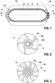
Fig. 2 shows a schematic view of a segmented high pressure tank according to embodiments of the present disclosure; -
Fig. 3 shows another schematic view of a segmented high pressure tank according to embodiments of the present disclosure; -
Fig. 4 shows a schematic view of winding pattern according to embodiments of the present disclosure; -
Fig. 5 shows a schematic view of winded layer of dry fibres of the first type according to embodiments of the present disclosure; -
Fig. 6 shows a schematic view of winded layer of dry fibres of the second type according to embodiments of the present disclosure; and -
Fig. 7 shows a flow chart of the method according to embodiments of the present disclosure. - It is to be noted that
Figs. 1-6 are schematic drawings and that no dimension and/or ratio may be derived fromFigs. 1-6 . - Reference will now be made in detail to exemplary embodiments of the disclosure, examples of which are illustrated in the accompanying drawings. Wherever possible, the same reference numbers will be used throughout the drawings to refer to the same or like parts.
-
Fig. 1 shows a representation of a partial cut out view of an exemplaryhigh pressure tank 10 according to exemplary embodiment of the present disclosure. Thehigh pressure tank 10 has a nominal working pressure equal to or greater than 200 bar. - As a non-limiting example, the
high pressure tank 10 may be a high pressure tank for compressed hydrogen. - The
high pressure tank 10 ofFig. 1 includes aplastic liner 12 having a cylindricalcentral part 12A and two dome-shapedextremities 12B. One of the dome-shapedextremities 12B has a firstmetallic boss 14 having anopening 24, for example for accommodating a valve. - In the embodiment of
Fig. 1 , the other dome-shapedextremity 12B also has a secondmetallic boss 30 having a hollowcentral part 26. The secondmetallic boss 30 may be a closed metallic boss, i.e., not having a through hole contrary to the firstmetallic boss 14. - The
high pressure tank 10 may include onemetallic boss 14, i.e., the firstmetallic boss 14, the secondmetallic boss 30 not being mandatory. - It is to be noted that the diameter of the hollow
central part 26 may be the same as the diameter of theopening 24 as shown onFig. 1 or the different as shown onFigs. 2 and 3 . - In the non-limiting example of
Fig. 1 , theplastic liner 12 is fully covered with a winded layer of dry fibres of afirst type 16. The firstmetallic boss 14 and the secondmetallic boss 30 are partially covered with the winded layer of dry fibres of thefirst type 16. Thewinded layer 16 of dry fibres of the first type is covered by a winded layer of dry fibres of thesecond type 18. - As non-limiting example, the winded layer of dry fibres of the
first type 16 may be obtained by helical winding, as shown onFig. 2 . - As non-limiting example, the winded layer of dry fibres of the
second type 18 may include afirst sub-layer 18A, for example a helical winding sub-layer, and asecond sub-layer 18B, for example a hoop winding sub-layer, as shown onFig. 6 . - Due to the cut out view of
Fig. 1 , the winded layer of dry fibres of thesecond type 18 is shown not fully covering the winded layer of dry fibres of thefirst type 16. Nonetheless, the winded layer of dry fibres of thesecond type 18 is fully covering the winded layer of dry fibres of thefirst type 16. - The winded layer of dry fibres of the
first type 16 is sandwiched between theplastic liner 12 and the winded layer of dry fibres of thesecond type 18. - The dry fibres of the first type have a higher abrasion resistance than the dry fibres of the second type.
- The winded layer of dry fibres of the
first type 16 is not adhering to theplastic liner 12, the firstmetallic boss 14 and the secondmetallic boss 30. - As non-limiting example, the dry fibres of the first type may be aramid fibres.
- Aramid fibres are known to have high abrasion resistance.
- Aramid fibres are known to have lower stiffness.
- As non-limiting example, the dry fibres of the second type may be carbon fibres.
- Carbon fibres are known to have superior mechanical properties, specifically regarding burst pressure.
- Aramid fibres have a higher abrasion resistance than carbon fibres.
- Aramid fibres have a lower stiffness than the carbon fibres.
- The
high pressure tank 10 ofFig. 1 may include aprotection layer 20. The winded layer of dry fibres of thesecond type 18 is sandwiched between the winded layer of dry fibres of thefirst type 16 and theprotection layer 20. - The
protection layer 20 is not mandatory. - As non-limiting example, the protection layer may be a polyurethane protection layer.
- Due to the cut out view of
Fig. 1 , theprotection layer 20 is shown not fully covering the winded layer of dry fibres of thesecond type 18. Nonetheless, in the embodiment ofFig. 1 , theprotection layer 20 is fully covering the winded layer of dry fibres of thesecond type 18. - As non-limiting example, the hoop winding sub-layer 18B of dry fibres of the second type may be winded on the
plastic liner 12, basically covering the cylindricalcentral part 12A of theplastic liner 12. The winded layer of dry fibres of thefirst type 16 may then be winded fully covering the hoop winding sub-layer 18B of dry fibres of the second type, the two dome-shapedextremities 12B of theplastic liner 12 and partially the firstmetallic boss 14 and the secondmetallic boss 30. The helical windingsub-layer 18A may be winded on the winded layer of dry fibres of thefirst type 16, fully covering the winded layer of dry fibres of thefirst type 16. Thus, the winded layer of dry fibres of thefirst type 16 is partially sandwiched between theplastic liner 12, in particular the two dome-shapedextremities 12B of theplastic liner 12, and the winded layer of dry fibres of thesecond type 18, in particular the helical windingsub-layer 18A. - It is understood that the winded layer of dry fibres of the
first type 16 and/or the winded layer of dry fibres of thesecond type 18 may include as many sub-layers as required for reinforcing theplastic liner 12 of thehigh pressure tank 10. - Based on
Figs. 2-7 , themethod 100 for producing thehigh pressure tank 10 ofFig. 1 is described. - As a
first step 102, the winded layer of dry fibres of thefirst type 16 is winded on theplastic liner 12 and themetallic boss 14. The winded layer of dry fibres of thefirst type 16 covers fully an external surface of theplastic liner 12 and covers partially an external surface of the firstmetallic boss 14 and an external surface of the secondmetallic boss 30, in particular a part of the external surface of the firstmetallic boss 14 that is flush with or close to theplastic liner 12 and a part of the external surface of the secondmetallic boss 30 that is flush with or close to theplastic liner 12. - As non-limiting example, the winded layer of dry fibres of the first type may include helical winding.
- As shown at
Figs. 2 and 3 , the dry fibres of the first type may be a bundle ofdry fibres 22. - As non-limiting example, the
plastic liner 12 shown atFig. 2 may be divided into five segments. - As non-limiting example, the
plastic liner 12 shown atFig. 3 may be divided into eleven segments. - As shown at
Figs. 2 and 3 , the segments are dividing the dome-shapedextremities 12B of theplastic liner 12. - Although shown at
Figs. 2 and 3 as individual segments for ease of understanding, the bundle ofdry fibres 22 is a continuous bundle which is continuously winded on theplastic liner 12. - The bundle of
dry fibres 22 of the first type may be winded with a helical winding, the bundle ofdry fibres 22 having a winding angle α with an axis X of theplastic liner 12, as shown onFig. 4 . - The axis X of the
plastic liner 12 is a rotational axis of symmetry of theplastic liner 12. - As non-limiting examples,
Figs. 2 and 3 show a first wound circuit for a five-segment and a eleven-segment winding respectively. - As non-limiting examples,
Figs. 2 and 3 show thefirst wound circuit 22A and the start of asecond wound circuit 22B. In thesecond wound circuit 22B, the bundle ofdry fibres 22 partially overlaps the bundle of dry fibres of thefirst wound circuit 22A. - More specifically,
Fig. 2 shows schematically the first metallic boss opening 24 representing the place where the firstmetallic boss 14 andFig. 3 shows schematically the second metallic boss hollowcentral part 26, the secondmetallic boss 30 being at the opposite of the firstmetallic boss 14. AlthoughFig. 2 and Fig. 3 show embodiments with different number of segments, the positioning of the firstmetallic boss opening 24 and of the second metallic boss hollowcentral part 26 may be the same. - As a non-limiting example, a twelve-segment winding helical layer may be obtained..
- As a non-limiting example, a five-segment winding helical layer may be obtained.
- The hoop winding of the
plastic liner 12, the firstmetallic boss 14 and the second metallic boss 30is carried out until theplastic liner 12 is fully covered with the bundle ofdry fibres 22 of the first type and the firstmetallic boss 14 and the secondmetallic boss 30 are partially covered with the bundle ofdry fibres 22 of the first type. - The winded layer of dry fibres of the
first type 16 is shown atFig. 5 where twospindles 28 are also represented. - The winded layer of dry fibres of the
first type 16 may include sub-layers of dry fibres of the first type, each sub-layer being defined as when the bundle offibres 22 reaches the starting point. - As a
second step 104, the winded layer of dry fibres of thesecond type 18 is winded on the winded layer of dry fibres of thefirst type 16. The winded layer of dry fibres of thesecond type 18 covers fully the winded layer of dry fibres of thefirst type 16. - As a non-limiting example, the dry fibres of the second type may be a bundle of dry fibres.
- As a non-limiting example, the
step 104 of winding dry fibres of the second type on the dry fibres of the first type may include two sub-steps: afirst sub-step 106 of winding afirst sub-layer 18A of dry fibres of the second type on the winded layer of dry fibres of thefirst type 16 and asecond sub-step 108 of winding asecond sub-layer 18B of dry fibres of the second type on thefirst sub-layer 18A. - As a non-limiting example, the
first sub-layer 18A may be a helical winding sub-layer and thesecond sub-layer 18B may be a hoop winding sub-layer.. - The winded layer of dry fibres of the
second type Fig. 6 where twospindles 28 are also represented. - As shown at
Fig. 6 , thefirst sub-layer 18A fully covers the winded layer of dry fibres of thefirst type 16 and thesecond sub-layer 18B partially covers thefirst sub-layer 18A. - The hoop winding sub-layer does not cover the dome shape of the
high pressure tank 10. - As a non-mandatory step, the
method 100 may include astep 110 of covering the winded layer of dry fibres of thesecond type 18 with theprotection layer 20. - As a non-limiting example, the
protection layer 20 may be made of polyurethane. - As a non-limiting example, the polyurethane may be applied in liquid form onto the winded layer of dry fibres of the
second type 18, and thus the liquid polyurethane may impregnate partially the winded layer of dry fibres of thesecond type 18 before the liquid polyurethane is cured. - Throughout the description, including the claims, the term "comprising a" should be understood as being synonymous with "comprising at least one" unless otherwise stated. In addition, any range set forth in the description, including the claims should be understood as including its end value(s) unless otherwise stated. Specific values for described elements should be understood to be within accepted manufacturing or industry tolerances known to one of skill in the art, and any use of the terms "substantially" and/or "approximately" and/or "generally" should be understood to mean falling within such accepted tolerances.
- Although the present disclosure herein has been described with reference to particular embodiments, it is to be understood that these embodiments are merely illustrative of the principles and applications of the present disclosure.
- It is intended that the specification and examples be considered as exemplary only, with a true scope of the disclosure being indicated by the following claims.
Claims (15)
- A high pressure tank (10) comprising:- a plastic liner (12) having a cylindrical central part and two dome-shaped extremities, at least one of the dome-shaped extremities having a metallic boss (14);- a winded layer of dry fibres of a first type (16);- a winded layer of dry fibres of a second type (18);the winded layer of dry fibres of the first type (16) being partially or fully sandwiched between the plastic liner (12) and the winded layer of dry fibres of the second type (18), the winded layer of dry fibres of the first type (16) partially covering an external surface of the metallic boss (14);the dry fibres of the first type having a higher abrasion resistance than the dry fibres of the second type;the winded layer of dry fibres of the first type (16) and the winded layer of dry fibres of the second type (18) not adhering to the plastic liner (12) and the winded layer of dry fibres of the first type (16) not adhering to the metallic boss (14);the high pressure tank (10) having a nominal working pressure equal to or greater than 200 bar.
- The high pressure tank (10) according to claim 1, wherein the dry fibres of the first type have a lower stiffness than the dry fibres of the second type.
- The high pressure tank (10) according to any of claims 1-2, wherein the winded layer of dry fibres of the first type (16) comprises helical winding.
- The high pressure tank according to any of claims 1-3, wherein the winded layer of dry fibres of the second type (18) comprises a hoop winding sub-layer and a helical winding sub-layer.
- The high pressure tank (10) according to any of claims 1-4, wherein the dry fibres of the first type and/or the second type are bundles of dry fibres (22).
- The high pressure tank (10) according to claim 5, wherein the bundles of dry fibres (22) are overlapping one another in a winded layer.
- The high pressure tank (10) according to any of claims 1-6, wherein the dry fibres of the second type are dry carbon fibres.
- The high pressure tank (10) according to any of claims 1-7, wherein the dry fibres of the first type are dry aramid fibres.
- The high pressure tank (10) according to any of claims 1-8, wherein the high pressure tank (10) comprises a protection layer (20), the winded layer of dry fibres of the second type (18) being sandwiched between the winded layer of dry fibres of the first type (16) and the protection layer (20).
- The high pressure tank (10) according to claim 9, wherein the winded layer of dry fibres of the second type (18) is partially impregnated with the protection layer (20).
- A method (100) for producing a high pressure tank (10) according to any of claims 1-10, the method comprising:- winding dry fibres of the first type (102) fully covering the plastic liner and partially covering the metallic boss;- winding dry fibres of the second type (104) on the dry fibres of the first type.
- The method (100) according to claim 11, wherein the dry fibres of the first type and/or the second type are bundles of dry fibres.
- The method (100) according to claim 11 or 12, wherein winding of dry fibres of the first type comprises helical winding.
- The method (100) according to any of claims 11-13, wherein winding of the dry fibres of the second type comprises hoop and helical winding.
- The method (100) according to any of claims 11-14 in combination with claim 9 or 10, wherein the method comprises covering (110) the dry fibres of the second type with the protection layer (20).
Priority Applications (1)
| Application Number | Priority Date | Filing Date | Title |
|---|---|---|---|
| EP23180003.8A EP4481261A1 (en) | 2023-06-19 | 2023-06-19 | High pressure tank and method for producing the same |
Applications Claiming Priority (1)
| Application Number | Priority Date | Filing Date | Title |
|---|---|---|---|
| EP23180003.8A EP4481261A1 (en) | 2023-06-19 | 2023-06-19 | High pressure tank and method for producing the same |
Publications (1)
| Publication Number | Publication Date |
|---|---|
| EP4481261A1 true EP4481261A1 (en) | 2024-12-25 |
Family
ID=86899196
Family Applications (1)
| Application Number | Title | Priority Date | Filing Date |
|---|---|---|---|
| EP23180003.8A Pending EP4481261A1 (en) | 2023-06-19 | 2023-06-19 | High pressure tank and method for producing the same |
Country Status (1)
| Country | Link |
|---|---|
| EP (1) | EP4481261A1 (en) |
Citations (4)
| Publication number | Priority date | Publication date | Assignee | Title |
|---|---|---|---|---|
| WO2013083652A2 (en) * | 2011-12-05 | 2013-06-13 | Blue Wave Co S.A. | Pressure vessel for fuel applications |
| EP3225900A1 (en) * | 2016-03-30 | 2017-10-04 | Plastic Omnium Advanced Innovation and Research | Pressure vessel and method for forming an outer layer of a pressure vessel |
| WO2019068813A1 (en) * | 2017-10-04 | 2019-04-11 | Plastic Omnium Advanced Innovation And Research | Pressure vessel and method for forming an outer layer of a pressure vessel |
| US20210247025A1 (en) * | 2018-06-26 | 2021-08-12 | Plastic Omnium Advanced Innovation And Research | Composite pressure vessel with reinforced inner liner and process for the production thereof |
-
2023
- 2023-06-19 EP EP23180003.8A patent/EP4481261A1/en active Pending
Patent Citations (4)
| Publication number | Priority date | Publication date | Assignee | Title |
|---|---|---|---|---|
| WO2013083652A2 (en) * | 2011-12-05 | 2013-06-13 | Blue Wave Co S.A. | Pressure vessel for fuel applications |
| EP3225900A1 (en) * | 2016-03-30 | 2017-10-04 | Plastic Omnium Advanced Innovation and Research | Pressure vessel and method for forming an outer layer of a pressure vessel |
| WO2019068813A1 (en) * | 2017-10-04 | 2019-04-11 | Plastic Omnium Advanced Innovation And Research | Pressure vessel and method for forming an outer layer of a pressure vessel |
| US20210247025A1 (en) * | 2018-06-26 | 2021-08-12 | Plastic Omnium Advanced Innovation And Research | Composite pressure vessel with reinforced inner liner and process for the production thereof |
Similar Documents
| Publication | Publication Date | Title |
|---|---|---|
| US6048428A (en) | Pipe construction | |
| EP3649393B1 (en) | Improved pressure vessel | |
| CN1252411C (en) | Fiber reinforced pressure vessel and manufacturing method thereof | |
| US8821667B2 (en) | Multilayer composite pressure vessel and method for making the same | |
| US4369894A (en) | Filament wound vessels | |
| US11597166B2 (en) | Method of manufacturing high-pressure tank | |
| EP3608090B1 (en) | Composite connector and method of manufacturing the same | |
| WO2013142178A1 (en) | Method of manufacturing a compressed gas cylinder | |
| KR20180119956A (en) | Method for manufacturing a pressure vessel | |
| EP4481261A1 (en) | High pressure tank and method for producing the same | |
| CN113910648A (en) | Method for manufacturing high-pressure tank | |
| KR20230114727A (en) | A pressure vessel for storing fluid | |
| US5248361A (en) | Method of manufacturing laminated flexible bearings, in particular for engine nozzle joints | |
| JP2008249021A (en) | Pressure vessel and method for manufacturing the same | |
| LU102845B1 (en) | Boss assembly for a pressure vessel | |
| KR102925289B1 (en) | High pressure container with boss reinforced winding and menufacturing method thereof | |
| JP7713099B2 (en) | Pressure vessel having an optimized outer composite structure | |
| US12594510B2 (en) | Reinforced membrane systems | |
| US12467587B2 (en) | Mandrel and test piece collecting method for filament winding | |
| JP2025126638A (en) | Pressure vessel and method for manufacturing pressure vessel | |
| CN117722585A (en) | Can | |
| JP2011136474A (en) | Method for manufacturing pressure container | |
| JP2018177898A (en) | Method of manufacturing tow prepreg wound body |
Legal Events
| Date | Code | Title | Description |
|---|---|---|---|
| PUAI | Public reference made under article 153(3) epc to a published international application that has entered the european phase |
Free format text: ORIGINAL CODE: 0009012 |
|
| STAA | Information on the status of an ep patent application or granted ep patent |
Free format text: STATUS: REQUEST FOR EXAMINATION WAS MADE |
|
| 17P | Request for examination filed |
Effective date: 20230619 |
|
| AK | Designated contracting states |
Kind code of ref document: A1 Designated state(s): AL AT BE BG CH CY CZ DE DK EE ES FI FR GB GR HR HU IE IS IT LI LT LU LV MC ME MK MT NL NO PL PT RO RS SE SI SK SM TR |
|
| GRAP | Despatch of communication of intention to grant a patent |
Free format text: ORIGINAL CODE: EPIDOSNIGR1 |
|
| STAA | Information on the status of an ep patent application or granted ep patent |
Free format text: STATUS: GRANT OF PATENT IS INTENDED |
|
| RIC1 | Information provided on ipc code assigned before grant |
Ipc: F17C 1/06 20060101AFI20251211BHEP |
|
| INTG | Intention to grant announced |
Effective date: 20251222 |
|
| GRAS | Grant fee paid |
Free format text: ORIGINAL CODE: EPIDOSNIGR3 |
|
| GRAA | (expected) grant |
Free format text: ORIGINAL CODE: 0009210 |
|
| STAA | Information on the status of an ep patent application or granted ep patent |
Free format text: STATUS: THE PATENT HAS BEEN GRANTED |