EP4481250A1 - Motorized valve control device, motorized valve device, and method for controlling motorized valve - Google Patents
Motorized valve control device, motorized valve device, and method for controlling motorized valve Download PDFInfo
- Publication number
- EP4481250A1 EP4481250A1 EP23752716.3A EP23752716A EP4481250A1 EP 4481250 A1 EP4481250 A1 EP 4481250A1 EP 23752716 A EP23752716 A EP 23752716A EP 4481250 A1 EP4481250 A1 EP 4481250A1
- Authority
- EP
- European Patent Office
- Prior art keywords
- rotor
- electric valve
- rotation
- control device
- stepping motor
- Prior art date
- Legal status (The legal status is an assumption and is not a legal conclusion. Google has not performed a legal analysis and makes no representation as to the accuracy of the status listed.)
- Pending
Links
Images






Classifications
-
- F—MECHANICAL ENGINEERING; LIGHTING; HEATING; WEAPONS; BLASTING
- F16—ENGINEERING ELEMENTS AND UNITS; GENERAL MEASURES FOR PRODUCING AND MAINTAINING EFFECTIVE FUNCTIONING OF MACHINES OR INSTALLATIONS; THERMAL INSULATION IN GENERAL
- F16K—VALVES; TAPS; COCKS; ACTUATING-FLOATS; DEVICES FOR VENTING OR AERATING
- F16K31/00—Actuating devices; Operating means; Releasing devices
- F16K31/02—Actuating devices; Operating means; Releasing devices electric; magnetic
- F16K31/04—Actuating devices; Operating means; Releasing devices electric; magnetic using a motor
- F16K31/046—Actuating devices; Operating means; Releasing devices electric; magnetic using a motor with electric means, e.g. electric switches, to control the motor or to control a clutch between the valve and the motor
-
- F—MECHANICAL ENGINEERING; LIGHTING; HEATING; WEAPONS; BLASTING
- F16—ENGINEERING ELEMENTS AND UNITS; GENERAL MEASURES FOR PRODUCING AND MAINTAINING EFFECTIVE FUNCTIONING OF MACHINES OR INSTALLATIONS; THERMAL INSULATION IN GENERAL
- F16K—VALVES; TAPS; COCKS; ACTUATING-FLOATS; DEVICES FOR VENTING OR AERATING
- F16K1/00—Lift valves or globe valves, i.e. cut-off apparatus with closure members having at least a component of their opening and closing motion perpendicular to the closing faces
- F16K1/32—Details
- F16K1/34—Cutting-off parts, e.g. valve members, seats
- F16K1/36—Valve members
- F16K1/38—Valve members of conical shape
-
- F—MECHANICAL ENGINEERING; LIGHTING; HEATING; WEAPONS; BLASTING
- F16—ENGINEERING ELEMENTS AND UNITS; GENERAL MEASURES FOR PRODUCING AND MAINTAINING EFFECTIVE FUNCTIONING OF MACHINES OR INSTALLATIONS; THERMAL INSULATION IN GENERAL
- F16K—VALVES; TAPS; COCKS; ACTUATING-FLOATS; DEVICES FOR VENTING OR AERATING
- F16K31/00—Actuating devices; Operating means; Releasing devices
- F16K31/44—Mechanical actuating means
- F16K31/50—Mechanical actuating means with screw-spindle or internally threaded actuating means
-
- F—MECHANICAL ENGINEERING; LIGHTING; HEATING; WEAPONS; BLASTING
- F16—ENGINEERING ELEMENTS AND UNITS; GENERAL MEASURES FOR PRODUCING AND MAINTAINING EFFECTIVE FUNCTIONING OF MACHINES OR INSTALLATIONS; THERMAL INSULATION IN GENERAL
- F16K—VALVES; TAPS; COCKS; ACTUATING-FLOATS; DEVICES FOR VENTING OR AERATING
- F16K37/00—Special means in or on valves or other cut-off apparatus for indicating or recording operation thereof, or for enabling an alarm to be given
- F16K37/0025—Electrical or magnetic means
- F16K37/0041—Electrical or magnetic means for measuring valve parameters
-
- F—MECHANICAL ENGINEERING; LIGHTING; HEATING; WEAPONS; BLASTING
- F25—REFRIGERATION OR COOLING; COMBINED HEATING AND REFRIGERATION SYSTEMS; HEAT PUMP SYSTEMS; MANUFACTURE OR STORAGE OF ICE; LIQUEFACTION SOLIDIFICATION OF GASES
- F25B—REFRIGERATION MACHINES, PLANTS OR SYSTEMS; COMBINED HEATING AND REFRIGERATION SYSTEMS; HEAT PUMP SYSTEMS
- F25B41/00—Fluid-circulation arrangements
- F25B41/30—Expansion means; Dispositions thereof
- F25B41/31—Expansion valves
- F25B41/34—Expansion valves with the valve member being actuated by electric means, e.g. by piezoelectric actuators
- F25B41/35—Expansion valves with the valve member being actuated by electric means, e.g. by piezoelectric actuators by rotary motors, e.g. by stepping motors
-
- H—ELECTRICITY
- H02—GENERATION; CONVERSION OR DISTRIBUTION OF ELECTRIC POWER
- H02P—CONTROL OR REGULATION OF ELECTRIC MOTORS, ELECTRIC GENERATORS OR DYNAMO-ELECTRIC CONVERTERS; CONTROLLING TRANSFORMERS, REACTORS OR CHOKE COILS
- H02P29/00—Arrangements for regulating or controlling electric motors, appropriate for both AC and DC motors
- H02P29/02—Providing protection against overload without automatic interruption of supply
- H02P29/024—Detecting a fault condition, e.g. short circuit, locked rotor, open circuit or loss of load
-
- H—ELECTRICITY
- H02—GENERATION; CONVERSION OR DISTRIBUTION OF ELECTRIC POWER
- H02P—CONTROL OR REGULATION OF ELECTRIC MOTORS, ELECTRIC GENERATORS OR DYNAMO-ELECTRIC CONVERTERS; CONTROLLING TRANSFORMERS, REACTORS OR CHOKE COILS
- H02P8/00—Arrangements for controlling dynamo-electric motors rotating step by step
- H02P8/24—Arrangements for stopping
-
- H—ELECTRICITY
- H02—GENERATION; CONVERSION OR DISTRIBUTION OF ELECTRIC POWER
- H02P—CONTROL OR REGULATION OF ELECTRIC MOTORS, ELECTRIC GENERATORS OR DYNAMO-ELECTRIC CONVERTERS; CONTROLLING TRANSFORMERS, REACTORS OR CHOKE COILS
- H02P8/00—Arrangements for controlling dynamo-electric motors rotating step by step
- H02P8/36—Protection against faults, e.g. against overheating or step-out; Indicating faults
-
- Y—GENERAL TAGGING OF NEW TECHNOLOGICAL DEVELOPMENTS; GENERAL TAGGING OF CROSS-SECTIONAL TECHNOLOGIES SPANNING OVER SEVERAL SECTIONS OF THE IPC; TECHNICAL SUBJECTS COVERED BY FORMER USPC CROSS-REFERENCE ART COLLECTIONS [XRACs] AND DIGESTS
- Y02—TECHNOLOGIES OR APPLICATIONS FOR MITIGATION OR ADAPTATION AGAINST CLIMATE CHANGE
- Y02B—CLIMATE CHANGE MITIGATION TECHNOLOGIES RELATED TO BUILDINGS, e.g. HOUSING, HOUSE APPLIANCES OR RELATED END-USER APPLICATIONS
- Y02B30/00—Energy efficient heating, ventilation or air conditioning [HVAC]
- Y02B30/70—Efficient control or regulation technologies, e.g. for control of refrigerant flow, motor or heating
Definitions
- the present invention relates to an electric valve control device, an electric valve device with the electric valve control device, and a method for controlling an electric valve.
- Patent Literature 1 discloses an example of an electric valve according to the related art.
- the electric valve is installed in a refrigeration cycle system of an air conditioner.
- the electric valve includes a valve body, a valve member, and a stepping motor for moving the valve member.
- the stepping motor includes a rotor and a stator.
- the rotor rotates in response to pulses input to the stepping motor.
- the electric valve includes a movement mechanism to move the valve member along with the rotation of the rotor.
- the rotor rotates within a range from a reference position to a full-open position.
- a movable stopper mounted on the rotor When the rotor is at the reference position, a movable stopper mounted on the rotor is in contact with a fixed stopper mounted on the valve body, restricting the rotation of the rotor in a valve closing direction.
- the valve member When the rotor is at the full-open position, the valve member is positioned farthest from a valve port of the valve body.
- the electric valve is controlled by an electric valve control device.
- the electric valve control device inputs pulses to the stepping motor to rotate the rotor in the valve closing direction and positions the rotor at the reference position.
- the number of the pulses input to the stepping motor is large enough to bring the movable stopper into contact with the fixed stopper.
- the number of the pulses is referred to as an initialization number.
- the initialization number is set to a number greater than the number of pulses in design input to the stepping motor when the rotor is rotated from the full-open position to the reference position.
- Patent Literature 1 WO2019/130928
- the electric valve control device In the initialization operation, the electric valve control device inputs pulses to the stepping motor until the number of pulses input to the stepping motor reaches the initialization number. However, if, for example, foreign matter in refrigerant enters the movement mechanism or the movement mechanism fails, the rotor may be stopped at a position between the reference position and the full-open position. Additionally, the movable and fixed stoppers wear due to repetitive contact. When the wear on the movable and fixed stoppers increases, the rotor may rotate in the valve closing direction far past the reference position and may be unable to be positioned at the reference position. As a result, the electric valve control device may start controlling the electric valve after the initialization operation even though the electric valve does not operate normally.
- an object of the present invention to provide an electric valve control device, an electric valve device with the electric valve control device, and a method for controlling an electric valve that are capable of determining whether a rotor is able to rotate normally within an appropriate rotation range.
- an electric valve control device is an electric valve control device for controlling an electric valve.
- the electric valve includes a valve body that has a valve port, a stepping motor that includes a rotor, a valve member that moves toward the valve port when the rotor rotates in a first direction and moves away from the valve port when the rotor rotates in a second direction, a first stopper mechanism that restricts rotation of the rotor in the first direction when the rotor is at a reference position, and a second stopper mechanism that restricts rotation of the rotor in the second direction when the rotor is at a full-open position.
- a state where the rotation of the rotor in the first direction is restricted is a first-direction-rotation restricted state.
- a state where the rotation of the rotor in the second direction is restricted is a second-direction-rotation restricted state.
- the number of pulses in design input to the stepping motor when the rotor is rotated from the full-open position to the reference position is a design number.
- an electric valve control device is an electric valve control device for controlling an electric valve.
- the electric valve includes a valve body that has a valve port, a stepping motor that includes a rotor, a valve member that moves toward the valve port when the rotor rotates in a first direction and moves away from the valve port when the rotor rotates in a second direction, a first stopper mechanism that restricts rotation of the rotor in the first direction when the rotor is at a reference position, and a second stopper mechanism that restricts rotation of the rotor in the second direction when the rotor is at a full-open position.
- a state where the rotation of the rotor in the first direction is restricted is a first-direction-rotation restricted state.
- a state where the rotation of the rotor in the second direction is restricted is a second-direction-rotation restricted state.
- the number of pulses in design input to the stepping motor when the rotor is rotated from the reference position to the full-open position is a design number.
- the electric valve control device is configured to obtain a voltage generated in a stator of the stepping motor by rotation of the rotor.
- the electric valve control device is configured to determine whether the electric valve is in the first-direction-rotation restricted state and whether the electric valve is in the second-direction-rotation restricted state, based on at least one of (i) an area of a waveform of the voltage, (ii) an amplitude of a wave periodically observed in the waveform of the voltage, and (iii) a periodic appearance of a new wave distinct from the wave periodically observed in the waveform of the voltage.
- the stator includes an A-phase stator and a B-phase stator, and driving currents corresponding to pulses input to the stepping motor are supplied to the A-phase and B-phase stators.
- the electric valve control device is configured to obtain a voltage generated in one of the A-phase and B-phase stators when the driving current is supplied only to the other of the A-phase and B-phase stators.
- an electric valve device is an electric valve device including the electric valve and the electric valve control device.
- a method according to still another aspect of the present invention is a method for controlling an electric valve.
- the electric valve includes a valve body that has a valve port, a stepping motor that includes a rotor, a valve member that moves toward the valve port when the rotor rotates in a first direction and moves away from the valve port when the rotor rotates in a second direction, a first stopper mechanism that restricts rotation of the rotor in the first direction when the rotor is at a reference position, and a second stopper mechanism that restricts rotation of the rotor in the second direction when the rotor is at a full-open position.
- a state where the rotation of the rotor in the first direction is restricted is a first-direction-rotation restricted state.
- a state where the rotation of the rotor in the second direction is restricted is a second-direction-rotation restricted state.
- the number of pulses in design input to the stepping motor when the rotor is rotated from the full-open position to the reference position is a design number.
- the method includes
- a method according to still another aspect of the present invention is a method for controlling an electric valve.
- the electric valve includes a valve body that has a valve port, a stepping motor that includes a rotor, a valve member that moves toward the valve port when the rotor rotates in a first direction and moves away from the valve port when the rotor rotates in a second direction, a first stopper mechanism that restricts rotation of the rotor in the first direction when the rotor is at a reference position, and a second stopper mechanism that restricts rotation of the rotor in the second direction when the rotor is at a full-open position.
- the rotation of the rotor in the first direction is restricted (the first-direction-rotation restricted state) by the first stopper mechanism when the rotor is rotated in the first direction
- the rotation of the rotor in the second direction is restricted (the second-direction-rotation restricted state) by the second stopper mechanism when the rotor is rotated in the second direction.
- the first and second stopper mechanisms wear due to restricting the rotation of the rotor. As the wear on the first stopper mechanism increases, the rotor can rotate in the first direction past the reference position. As the wear on the second stopper mechanism increases, the rotor can rotate in the second direction past the full-open position.
- An electric valve device according to an embodiment of the present invention is described with reference to Figs. 1 to 17 .
- An electric valve device 1 according to the embodiment is used as, for example, a flow control valve for controlling the flow rate of refrigerant in a refrigeration cycle system of an air conditioner.
- Fig. 1 is a block diagram of an air conditioning system including the electric valve device according to the embodiment of the present invention.
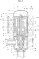
- Fig. 2 is a sectional view of the electric valve device in Fig. 1 .
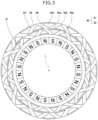
- Fig. 3 is a diagram illustrating a rotor and a stator that are included in the electric valve device in Fig. 2 .
- Fig. 3 schematically illustrates the rotor and the stator.
- Fig. 4 is a diagram illustrating a computer, a motor driver, and a stepping motor (the rotor and the stator) that are included in the electric valve device in Fig. 2 .
- Fig. 4A schematically illustrates connections among the computer and the motor driver that are included in an electric valve control device, and the stepping motor.
- Fig. 1 is a block diagram of an air conditioning system including the electric valve device according to the embodiment of the present invention.
- Fig. 2 is a sectional view of the electric valve device in Fig. 1 .
- FIG. 4B shows an example of correspondence between pulses and driving currents supplied to the stator by the motor driver.
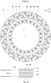
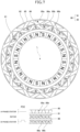
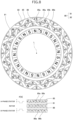
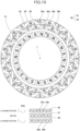
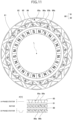
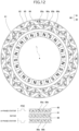
- Figs. 5 to 12 are diagrams schematically illustrating positional relationships between magnetic poles of the rotor and pole teeth of the stator. Figs. 5 to 12 correspond to when pulses P[1] to P[8] are input. Figs. 5 to 12 schematically illustrate the rotor and the stator.
- Fig. 13 is a diagram showing an example of a waveform of a voltage generated in the stator by rotation of the rotor in an initialization operation of the electric valve device.
- Fig. 14 is an enlarged view of a part (in time period T1) of the waveform of the voltage in Fig. 13 .
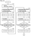
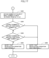
- Figs. 16 and 17 are flowcharts illustrating an example of the initialization operation performed by the computer included in the electric valve device in Fig. 2 .
- Fig. 1 illustrates an example of an air conditioning system 100 mounted in a vehicle.
- the air conditioning system 100 includes a compressor 101, a condenser 102, the electric valve device 1 (an electric valve 5), and an evaporator 103, which are connected in this order by a pipe 105.
- the electric valve device 1 functions as an expansion valve.
- the air conditioning system 100 includes an air conditioner control device 110.
- the air conditioner control device 110 is connected to the electric valve device 1 and can communicate with the electric valve device 1.
- the air conditioner control device 110 uses the electric valve device 1 to control the flow rate of refrigerant flowing through the pipe 105.
- the electric valve device 1 includes the electric valve 5 and an electric valve control device 90.
- the electric valve 5 includes a valve body 10, a can 30, a valve member 40, a valve stem 50, a coupling mechanism 60, a guide stem member 70, and a stepping motor 80.
- the valve body 10 includes a body member 11 and a valve seat member 21.
- the body member 11 has a circular cylindrical shape.
- the valve seat member 21 has a disc shape.
- the valve seat member 21 is bonded to the lower end of the body member 11.
- the valve seat member 21 has a valve port 22 and a valve seat 23.
- the valve port 22 is a circular hole extending through the center of the valve seat member 21 in an up-and-down direction (a direction of an axis L).
- the valve seat 23 is a circular annular tapered surface provided on the upper surface of the valve seat member 21. The valve seat 23 encloses the valve port 22.
- the valve body 10 has a valve chamber 14.
- a first conduit 18 is brazed to the body member 11.
- the first conduit 18 extends through the body member 11 in a lateral direction (a left-and-right direction in Fig. 2 ).
- the first conduit 18 is connected to the valve chamber 14.
- a second conduit 28 is brazed to the valve seat member 21.
- the second conduit 28 is disposed in the up-and-down direction.
- the second conduit 28 is connected to the valve port 22.
- the can 30 has a circular cylindrical shape.
- the can 30 is open at the lower end and is closed at the upper end.
- the outer diameter of the can 30 is equal to that of the body member 11.
- the inner diameter of the can 30 is larger than that of the body member 11.
- the can 30 is mounted on the upper end surface of the body member 11. Specifically, the lower end of the can 30 is welded to the outer peripheral edge of the upper end surface of the body member 11.
- the valve member 40 includes a stem portion 41, a valve portion 42, and a sleeve 43.
- the stem portion 41 has a circular columnar shape.
- the valve portion 42 has a conical shape with the tip end pointing downward.
- the valve portion 42 is provided coaxially and continuously with the lower end of the stem portion 41.
- the sleeve 43 has a circular cylindrical shape.
- the stem portion 41 extends through the sleeve 43.
- the sleeve 43 is secured to the stem portion 41.
- the valve member 40 is disposed in the valve chamber 14.
- the valve member 40 faces the valve port 22 in the up-and-down direction.
- the valve portion 42 comes into contact with the valve seat 23 and moves away from the valve seat 23.
- the valve port 22 is open, and the electric valve 5 is in a valve opening state.
- the first conduit 18 is connected to the second conduit 28 through the valve chamber 14.
- the valve port 22 is closed, and the electric valve 5 is in a valve closing state.
- the first conduit 18 is separated from the second conduit 28.
- the valve stem 50 includes a first part 51, a second part 52, and a third part 53.
- the first part 51 has a circular columnar shape.
- the first part 51 includes an external thread 51c on the outer circumferential surface.
- the second part 52 has a circular columnar shape.
- the outer diameter of the second part 52 is smaller than that of the first part 51.
- the second part 52 is provided coaxially and continuously with the upper end of the first part 51.
- the third part 53 has a disc shape.
- the outer diameter of the third part 53 is larger than that of the first part 51.
- the third part 53 is provided coaxially and continuously with the lower end of the first part 51.
- An upper stopper member 55 is mounted on the upper end of the first part 51.
- a lower stopper member 56 is mounted on the lower end of the first part 51.
- the coupling mechanism 60 combines the valve member 40 with the valve stem 50.
- the coupling mechanism 60 includes a holder 61, a valve-member supporting member 62, a spacer 63, a spring receiving member 65, and a valve closing spring 66.
- the holder 61 has a circular cylindrical shape.
- the holder 61 is open at the lower end and is closed at the upper end.
- the holder 61 is fixed to the third part 53 of the valve stem 50.
- the valve stem 50 includes a fixing portion 54 that has a circular cylindrical shape extending downward from the lower surface of the third part 53, and the fixing portion 54 is inserted into a through hole provided in an upper wall portion 61a of the holder 61 and is then expanded in diameter. This causes the upper wall portion 61a to be held by the third part 53 and the fixing portion 54.
- the inner space of the holder 61 is connected to the valve chamber 14 through a pressure equalizing hole 61b.
- the valve-member supporting member 62 has a circular annular plate-like shape.
- the lower end of the holder 61 is crimped to hold the outer peripheral edge of the valve-member supporting member 62.
- the spacer 63 has a circular annular plate-like shape.
- the spacer 63 is disposed on the upper surface of the valve-member supporting member 62.
- the stem portion 41 of the valve member 40 extends through the valve-member supporting member 62 and the spacer 63.
- the sleeve 43 of the valve member 40 inhibits the stem portion 41 from coming off the valve-member supporting member 62.
- the valve-member supporting member 62 supports the valve member 40 movably in up-and-down direction.
- the spring receiving member 65 has a circular cylindrical shape.
- the spring receiving member 65 includes a flange 65a projecting radially outward at the lower end.
- the spring receiving member 65 is disposed inside the holder 61 movably in up-and-down direction.
- the lower surface of the spring receiving member 65 is in contact with the upper end of the stem portion 41 of the valve member 40.
- the valve closing spring 66 is a compression coil spring.
- the valve closing spring 66 is disposed between the upper wall portion 61a of the holder 61 and the flange 65a of the spring receiving member 65.
- the valve closing spring 66 presses the spring receiving member 65 to the stem portion 41 of the valve member 40.
- the valve closing spring 66 pushes the valve member 40 downward via the spring receiving member 65.
- the valve member 40 may be connected directly to the valve stem 50 without the coupling mechanism 60.
- the circular columnar portion 71 includes an upper stopper portion 75 at the upper end.
- the circular columnar portion 71 includes a lower stopper portion 76 at the lower end.
- the circular columnar portion 71 includes an internal thread 71c extending through the center of the circular columnar portion 71 in the up-and-down direction. The external thread 51c of the valve stem 50 is screwed into the internal thread 71c.
- the circular cylindrical portion 72 is provided continuously with the lower end of the circular columnar portion 71.
- the third part 53 of the valve stem 50, the lower stopper member 56, and the coupling mechanism 60 are disposed inside the circular cylindrical portion 72.
- the inner diameter of the circular cylindrical portion 72 is equal to the outer diameter of the holder 61.
- the circular cylindrical portion 72 supports the holder 61 movably in the up-and-down direction.
- the holding portion 73 is an annular projection.
- the holding portion 73 projects radially outward from the outer circumferential surface of the circular cylindrical portion 72.
- the circular plate 74 has an annular shape.
- the inner peripheral edge of the circular plate 74 is embedded in the holding portion 73.
- the outer peripheral edge of the circular plate 74 is welded to the inner peripheral edge of the upper end surface of the body member 11.
- the guide stem member 70 is fixed to the valve body 10.
- the stepping motor 80 includes a rotor 81 and a stator 82.
- the rotor 81 has a circular cylindrical shape.
- the rotor 81 is open at the lower end and is closed at the upper end.
- the rotor 81 has a plurality of north (N) poles and a plurality of south (S) poles.
- the N poles and the S poles are disposed on the outer circumferential surface of the rotor 81.
- the N poles and the S poles each extend in the up-and-down direction. As illustrated in Fig. 3 , the N poles and the S poles are alternately arranged at regular angular intervals in the circumferential direction.
- the rotor 81 has, for example, twelve N poles and twelve S poles. The angle between the N pole and the S pole adjacent to each other is 15 degrees.
- the rotor 81 is disposed rotatably inside the can 30.
- the rotor 81 includes an upper wall portion 81a combined with the second part 52 of the valve stem 50 via a coupling element 83.
- the valve stem 50 rotates together with the rotor 81.
- the screw-feed action of the external thread 51c of the valve stem 50 and the internal thread 71c of the guide stem member 70 moves the valve stem 50, the coupling mechanism 60, and the valve member 40 in the up-and-down direction.
- the valve stem 50 and the guide stem member 70 are members of a movement mechanism to move the valve member 40 along with the rotation of the rotor 81.
- the stator 82 has a circular cylindrical shape.
- the stator 82 is disposed outside the can 30.
- the stator 82 includes an A-phase stator 85 and a B-phase stator 86.
- the A-phase stator 85 includes a plurality of claw-pole type pole teeth 85a and 85b in the inner circumference.
- the radially outward direction in the A-phase stator 85 corresponds to upward, and the radially inward direction corresponds to downward.
- the tip ends of the pole teeth 85a point downward, and the tip ends of the pole teeth 85b point upward.
- the pole teeth 85a and the pole teeth 85b are alternately arranged at regular angular intervals in the circumferential direction.
- the A-phase stator 85 has, for example, twelve pole teeth 85a and twelve pole teeth 85b.
- the angle between the pole tooth 85a and the pole tooth 85b adjacent to each other is 15 degrees.
- the B-phase stator 86 includes a plurality of claw-pole type pole teeth 86a and 86b in the inner circumference.
- the radially outward direction in the B-phase stator 86 corresponds to upward, and the radially inward direction corresponds to downward.
- the tip ends of the pole teeth 86a point downward, and the tip ends of the pole teeth 86b point upward.
- the pole teeth 86a and the pole teeth 86b are alternately arranged at regular angular intervals in the circumferential direction.
- the B-phase stator 86 has, for example, twelve pole teeth 86a and twelve pole teeth 86b.
- the angle between the pole tooth 86a and the pole tooth 86b adjacent to each other is 15 degrees.
- the A-phase stator 85 is disposed coaxially on the B-phase stator 86.
- the A-phase stator 85 is in contact with the B-phase stator 86.
- the angle between the pole tooth 85a of the A-phase stator 85 and the pole tooth 86a of the B-phase stator 86 adjacent to each other is 7.5 degrees.
- the B-phase stator 86 is in a position where the B-phase stator 86 is rotated relatively to the A-phase stator 85 about the axis L by 7.5 degrees from a position where the pole tooth 85a and the pole tooth 86a are arranged in the direction of the axis L.
- terminals A1 and A2 of the coil 85c of the A-phase stator 85 and terminals B1 and B2 of the coil 86c of the B-phase stator 86 are connected to a motor driver 94 of the electric valve control device 90.
- the rotor 81 is rotated by pulses P (pulses P[1] to P[8]) input to the stepping motor 80. Specifically, the rotor 81 is rotated by driving currents, corresponding to pulses P, supplied to the stator 82 of the stepping motor 80.
- pulses P pulses P[1] to P[8]
- the rotor 81 is rotated by driving currents, corresponding to pulses P, supplied to the stator 82 of the stepping motor 80.
- driving currents, corresponding to pulses P supplied to the stator 82 of the stepping motor 80.
- Pulses P[1] to P[8] illustrated in Fig. 4B are input to the stepping motor 80 in order.
- Figs. 5 to 12 illustrate examples of positional relationships between the rotor 81 and the stator 82 when pulses P[1] to P[8] are input.
- the reference pole tooth 85a and the reference magnetic pole (S pole) of the rotor 81 are marked with a dot for easy understanding of the positional relationship between the rotor 81 and the stator 82 (the A-phase stator 85 and the B-phase stator 86).
- pulses P are cyclically input to the stepping motor 80 in ascending order (in the order from pulse P[1] to pulse P[8]).
- the valve stem 50 is rotated in the first direction together with the rotor 81.
- the screw-feed action of the external thread 51c of the valve stem 50 and the internal thread 71c of the guide stem member 70 moves the valve stem 50 downward.
- the coupling mechanism 60 and the valve member 40 move downward together with the valve stem 50.
- the valve member 40 comes into contact with the valve seat 23, and the valve port 22 is closed (the valve closing state). At this time, the rotor 81 is at a valve closing position Rc.
- the valve closing spring 66 is compressed, and the coupling mechanism 60 (the holder 61 and the valve-member supporting member 62) further moves downward together with the valve stem 50.
- the valve member 40 does not move downward.
- the upper stopper member 55 comes into contact with the upper stopper portion 75 of the guide stem member 70, the rotation of the rotor 81 in the first direction is restricted.
- the rotor 81 is at a reference position Rx.
- the upper stopper member 55 and the upper stopper portion 75 are members of a first stopper mechanism S1 that restricts the rotation of the rotor 81 in the first direction.
- pulses P are cyclically input to the stepping motor 80 in descending order (in the order from pulse P[8] to pulse P[1]).
- the valve stem 50 is rotated in the second direction together with the rotor 81.
- the screw-feed action of the external thread 51c of the valve stem 50 and the internal thread 71c of the guide stem member 70 moves the valve stem 50 upward.
- the coupling mechanism 60 (the holder 61 and the valve-member supporting member 62) moves upward together with the valve stem 50.
- the valve member 40 moves upward together with the valve-member supporting member 62, the valve member 40 moves away from the valve seat 23, and valve port 22 is open (the valve opening state).
- the rotor 81 is further rotated in the second direction.
- the rotation of the rotor 81 in the second direction is restricted.
- the rotor 81 is at a full-open position Rz.
- the valve member 40 is positioned farthest from the valve port 22.
- the lower stopper member 56 and the lower stopper portion 76 are members of a second stopper mechanism S2 that restricts the rotation of the rotor 81 in the second direction.
- the respective central axes of the valve body 10 (the body member 11, the valve seat member 21, the valve port 22, and the valve seat 23), the can 30, the valve member 40, the valve stem 50, the coupling mechanism 60 (the holder 61 and the spring receiving member 65), the guide stem member 70 (the circular columnar portion 71, the circular cylindrical portion 72, and the circular plate 74), and the stepping motor 80 (the rotor 81 and the stator 82) are aligned with the axis L.
- the body member 11, the valve seat member 21, the can 30, the valve member 40, and the valve stem 50 are made of a metal, such as stainless steel.
- the guide stem member 70 is made of synthetic resin.
- the electric valve control device 90 includes a circuit board 91 on which electronic components (not illustrated) are mounted. As illustrated in Fig. 1 , the electric valve control device 90 includes a non-volatile memory 92, a communication device 93, the motor driver 94, and a computer 95. The electric valve control device 90 controls the electric valve 5 according to a command received from the air conditioner control device 110.
- the non-volatile memory 92 stores data required to be held even if power is turned off.
- the non-volatile memory 92 is, for example, EEPROM or flash memory.
- the non-volatile memory 92 stores a design number Xd and an upper limit number Xu.
- the design number Xd is the number of pulses in design input to the stepping motor 80 when the rotor 81 is rotated from the full-open position Rz to the reference position Rx (or the rotor 81 is rotated from the reference position Rx to the full-open position Rz).
- the first stopper mechanism S1 and the second stopper mechanism S2 wear due to restricting the rotation of the rotor 81. As the wear on the first stopper mechanism S1 increases, the rotor 81 can rotate in the first direction past the reference position Rx. As the wear on the second stopper mechanism S2 increases, the rotor 81 can rotate in the second direction past the full-open position Rz. This causes the rotatable range of the rotor 81 to expand.
- the upper limit number Xu is set to a number greater than the design number Xd by considering the expansion of the rotatable range due to the wear. Specifically, the upper limit number Xu is set to a number that is increased from the design number Xd according to the allowable amount of the wear on the first stopper mechanism S1 and the second stopper mechanism S2. For example, the upper limit number Xu is set to a number that is 105% to 120% of the design number Xd.
- the rotation range of the rotor 81 when the upper limit number Xu of pulses P are input to the stepping motor 80 is a maximum rotatable range W including a range from the full-open position Rz to the reference position Rx. When the rotor 81 can rotate at least within the range from the full-open position Rz to the reference position Rx and at most within the maximum rotatable range W, the rotor 81 can rotate in an appropriate rotation range.
- the communication device 93 is connected to the air conditioner control device 110 via a wired communication bus 120 and is able to communicate with the air conditioner control device 110.
- the air conditioning system 100 utilizes a communication system such as Local Interconnect Network (LIN) or Controller Area Network (CAN).
- the communication device 93 may be wirelessly connected to the air conditioner control device 110 and be able to wirelessly communicate with the air conditioner control device 110.
- the motor driver 94 supplies the driving currents to the stepping motor 80 based on pulses P input from the computer 95.
- Fig. 4B illustrates an example of correspondence between pulses P and the driving currents supplied by the motor driver 94.
- (+) denotes supplying the driving current flowing from the terminal A1 to the terminal A2 or the driving current flowing from the terminal B1 to the terminal B2.
- (+) denotes supplying the driving current flowing from the terminal A2 to the terminal A1 or the driving current flowing from the terminal B2 to the terminal B1.
- (0) denotes supplying no driving current.
- the motor driver 94 supplies the coil 85c with the driving current flowing from the terminal A1 to the terminal A2 (+) and supplies the coil 86c with no driving current (0).
- the motor driver 94 supplies the coil 85c with the driving current flowing from the terminal A1 to the terminal A2 (+) and supplies the coil 86c with the driving current flowing from the terminal B1 to the terminal B2 (+).
- the motor driver 94 supplies the coil 85c with no driving current (0) and supplies the coil 86c with the driving current flowing from the terminal B1 to the terminal B2 (+).
- the motor driver 94 supplies the coil 85c with the driving current flowing from the terminal A2 to the terminal A1 (-) and supplies the coil 86c with the driving current flowing from the terminal B1 to the terminal B2 (+).
- the motor driver 94 supplies the coil 85c with the driving current flowing from the terminal A2 to the terminal A1 (-) and supplies the coil 86c with no driving current (0).
- the motor driver 94 supplies the coil 85c with the driving current flowing from the terminal A2 to the terminal A1 (-) and supplies the coil 86c with the driving current flowing from the terminal B2 to the terminal B1 (-).
- the motor driver 94 supplies the coil 85c with no driving current (0) and supplies the coil 86c with the driving current flowing from the terminal B2 to the terminal B1 (-).
- the motor driver 94 supplies the coil 85c with the driving current flowing from the terminal A1 to the terminal A2 (+) and supplies the coil 86c with the driving current flowing from the terminal B2 to the terminal B1 (-).
- the computer 95 is a microcomputer for embedded devices that incorporates a CPU, ROM, RAM, an input/output interface, an analog-to-digital converter, or the like in a single package.
- the computer 95 may incorporate the non-volatile memory 92, the communication device 93, and the motor driver 94.
- the CPU executes a program stored in the ROM, and the computer 95 consequently functions as a rotation control unit 96, a voltage obtaining unit 97, and a state determining unit 98.
- the voltage obtaining unit 97 obtains a voltage generated in the stator 82 by the rotation of the rotor 81 (a voltage induced in the stator 82 due to electromagnetic induction). Specifically, the voltage obtaining unit 97 sequentially obtains the voltages VB generated between the terminals B1 and B2 of the coil 86c of the B-phase stator 86 when the rotation control unit 96 supplies the driving currents corresponding to pulses P[1] and P[5] only to the coil 85c of the A-phase stator 85.
- the voltage obtaining unit 97 sequentially obtains the voltages VA generated between the terminals A1 and A2 of the coil 85c of the A-phase stator 85 when the rotation control unit 96 supplies the driving currents corresponding to pulses P[3] and P[7] only to the coil 86c of the B-phase stator 86.
- the voltage obtaining unit 97 does not obtain the voltage VA or VB when the rotation control unit 96 supplies the driving currents corresponding to pulses P[2], P[4], P[6], and P[8] to the coils 85c and 86c.
- the voltage obtaining unit 97 may sequentially obtain the voltages VA and VB when the rotation control unit 96 supplies the driving currents corresponding to pulses P[1] to P[8] to the coils 85c and 86c.
- the voltage obtaining unit 97 separates a voltage component due to electromagnetic induction from the voltage generated between the terminals A1 and A2 and obtains the voltage component as the voltage VA.
- the voltage obtaining unit 97 separates a voltage component due to electromagnetic induction from the voltage generated between the terminals B1 and B2 and obtains the voltage component as the voltage VB.
- the voltages VA sequentially obtained form a waveform of the voltage VA.
- the voltages VB sequentially obtained form a waveform of the voltage VB.
- the state determining unit 98 determines the state of the electric valve 5 based on the waveforms of the voltages VA and VB obtained by the voltage obtaining unit 97 in an operation to position the rotor 81 at the reference position Rx.
- the operation is referred to as an initialization operation.
- the electric valve 5 has a rotation permitted state Sp, a first-direction-rotation restricted state Sr1, and a second-direction-rotation restricted state Sr2.
- the rotation permitted state Sp is where the rotation of the rotor 81 in the first direction is permitted and the rotation of the rotor 81 in the second direction is permitted.
- the first-direction-rotation restricted state Sr1 is where the rotation of the rotor 81 in the first direction is restricted.
- the second-direction-rotation restricted state Sr2 is where the rotation of the rotor 81 in the second direction is restricted.
- waveform refers to the variations in a physical quantity (voltage) over time at a fixed point.
- Waveform is represented on a coordinate plane for visualization, with the vertical axis corresponding to physical quantity and the horizontal axis corresponding to time.
- the word “waveform” can also refer to physical quantity data associated with time data, such as a data table, stored in the RAM of the computer 95 or the non-volatile memory 92.
- area of the waveform refers to an area of a region enclosed by the waveform and the horizontal axis.
- a method for determining the state of the electric valve 5 based on the waveforms of the voltages VA and VB by the state determining unit 98 is described.
- Figs. 13 to 15 illustrate examples of the waveforms of the voltages VA and VB measured in the initialization operation.
- pulses P[1] to P[8] are input to the stepping motor 80 in ascending order.
- the waveforms of the voltages VA and VB in time periods before time period T1 are not illustrated in Fig. 13 but are equal (including substantially equal) to the waveforms of the voltages VA and VB in time period T1.
- the electric valve device 1 has, for example, a period of pulse P of 8 milliseconds and a time period T of 64 milliseconds.
- pulses P[1] to P[8] are input to the stepping motor 80.
- valve member 40 comes into contact with the valve seat 23, and the rotor 81 is positioned at the valve closing position Rc.
- the upper stopper member 55 comes into contact with the upper stopper portion 75, and the rotor 81 is positioned at the reference position Rx.
- the rotation of the rotor 81 in the first direction is permitted before time tx and is restricted after time tx.
- the waveform of the voltage VA includes A-waves (a1 to a9), B-waves (b1 to b9), C-waves (c1 to c9), D-waves (d1 to d9), and E-waves (e7 to e9).
- A-waves and B-waves are negative voltage waves (-V) periodically observed in all time periods T.
- C-waves and D-waves are positive voltage waves (+V) periodically observed in all time periods T.
- E-waves are positive voltage waves (+V) periodically observed after time tx.
- the waves each have an amplitude larger than or equal to a predetermined magnitude.
- the areas SA1 to SA9 When the areas of the waveform (waveform including C-waves and D-waves) in the sections corresponding to pulse P[7] in time periods T1 to T9 are referred to as areas SA1 to SA9, the areas SA6 to SA9 in time periods T6 to T9 after time tx are smaller than the areas SA1 to SA5 in time periods T1 to T5 before time tx.
- D-waves (d1 to d5) are positive voltage waves with relatively large amplitudes before time tx
- D-waves (d6 to d9) are positive voltage waves with relatively small amplitudes after time tx.
- E-waves are observed before time tx, and E-waves (e7 to e9) are periodically observed after time tx.
- E-waves are new waves distinct from periodically observed waves in all time periods T and appear periodically after time tx.
- the waveform of the voltage VB includes F-waves (f1 to f9), G-waves (g1 to g9), H-waves (h1 to h9), J-waves (j1 to j9), K-waves (k1 to k9), and M-waves (m7 to m9).
- F-waves and G-waves are positive voltage waves (+V) periodically observed in all time periods T.
- H-waves, J-waves, and K-waves are negative voltage waves (-V) periodically observed in all time periods T.
- M-waves are positive voltage waves (+V) periodically observed after time tx.
- the waves each have an amplitude larger than or equal to a predetermined magnitude.
- the areas SB1 to SB9 in time periods T7 to T9 after time tx are smaller than the areas SB1 to SB6 in time periods T1 to T6 before time tx.
- G-waves (g1 to g6) are positive voltage waves with relatively large amplitudes before time tx, and G-waves (g7 to g9) are negative voltage waves with relatively small amplitudes after time tx.
- a G-wave (each of g7 to g9) is joined with an H-wave after time tx, resulting in one wave.
- K-waves (k1 to k5) are negative voltage waves with relatively small amplitudes before time tx
- K-waves (k7 to k9) are negative voltage waves with relatively large amplitudes after time tx.
- M-waves are observed before time tx, and M-waves (m7 to m9) are periodically observed after time tx.
- M-waves are new waves distinct from waves periodically observed in all time periods T and appear periodically after time tx.
- the waveforms of the voltages VA and VB have differences before and after time tx.
- the differences are as follows.
- the area of the waveform in time period T after time tx is smaller than the area of the waveform in time period T before time tx.
- the amplitude of the wave after time tx is different from the amplitude of the wave before time tx.
- New waves distinct from waves observed before time tx appear periodically after time tx.
- the waveforms of the voltages VA and VB have differences, in the same manner as the waveforms in Figs. 13 to 15 , between before and after the rotation of the rotor 81 in the second direction is restricted by the second stopper mechanism S2. Additionally, when, for example, foreign matter enters the movement mechanism (the valve stem 50 and the guide stem member 70) or the movement mechanism fails, the rotation of the rotor 81 is restricted. In such cases, the waveforms of the voltages VA and VB also have differences, in the same manner as the waveforms in Figs. 13 to 15 , between before and after the rotation of the rotor 81 is restricted.
- the state determining unit 98 can determine that the rotation of the rotor 81 in the first direction is restricted and that the rotation of the rotor 81 in the second direction is restricted by detecting at least one of the events according to (i) to (iii) described above in the waveforms of the voltages VA and VB.
- the state determining unit 98 determines that the electric valve 5 is in the second-direction-rotation restricted state Sr2 when at least one of the events according to (i) to (iii) described above is detected while the rotor 81 is rotated in the second direction.
- the state determining unit 98 may determine that the electric valve 5 is in the first-direction-rotation restricted state Sr1 when two or more of the events according to (i) to (iii) described above are detected while the rotor 81 is rotated in the first direction.
- the state determining unit 98 may determine that the electric valve 5 is in the second-direction-rotation restricted state Sr2 when two or more of the events according to (i) to (iii) described above are detected while the rotor 81 is rotated in the second direction.
- the state determining unit 98 may determine that the electric valve 5 is in the rotation permitted state Sp when the electric valve 5 is not in the first-direction-rotation restricted state Sr1 or the second-direction-rotation restricted state Sr2.
- the state determining unit 98 determines the state of the electric valve 5 at the end of the present time period T in which pulses P[1] to P[8] are input. Specifically, the state determining unit 98 performs items (1) to (8) below.
- the state determining unit 98 may be configured to tentatively determine the state of the electric valve 5 in the items (1) to (7). In this configuration, the state determining unit 98 definitely determines that the electric valve 5 is in the first-direction-rotation restricted state Sr1 when the state determining unit 98 tentatively determines multiple times (for example, two or more times) that the electric valve 5 is in the first-direction-rotation restricted state Sr1. The state determining unit 98 determines that the electric valve 5 is in the rotation permitted state Sp when the state determining unit 98 does not definitely determine that the electric valve 5 is in the first-direction-rotation restricted state Sr1.
- the state determining unit 98 determines, in the same manner, whether the state of the electric valve 5 is the second-direction-rotation restricted state Sr2 or the rotation permitted state Sp when the rotor 81 is rotated in the second direction.
- the electric valve control device 90 (specifically, the computer 95) receives an initializing command from the air conditioner control device 110 (S110), the electric valve control device 90 starts inputting pulses P to the stepping motor 80 in descending order to rotate the rotor 81 in the second direction (S120).
- the electric valve control device 90 functions as the rotation control unit 96.
- the driving currents corresponding to pulses P are supplied to the stator 82, and the rotor 81 is rotated in the second direction.
- the electric valve control device 90 sequentially obtains the voltages VA generated between the terminals A1 and A2 of the coil 85c of the A-phase stator 85 and the voltages VB generated between the terminals B1 and B2 of the coil 86c of the B-phase stator 86 (S130).
- the electric valve control device 90 functions as the voltage obtaining unit 97.
- the electric valve control device 90 When the electric valve 5 is in the rotation permitted state Sp (N in S150), the electric valve control device 90 repeatedly performs Steps S130 to S150.
- the electric valve control device 90 stops inputting pulses P to the stepping motor 80 (S160).
- the electric valve control device 90 starts inputting pulses P to the stepping motor 80 in ascending order to rotate the rotor 81 in the first direction (S170).
- the driving currents corresponding to pulses P are supplied to the stator 82, and the rotor 81 is rotated in the first direction.
- the electric valve control device 90 functions as the rotation control unit 96.
- the electric valve control device 90 determines the state (the first-direction-rotation restricted state Sr1 or the rotation permitted state Sp) of the electric valve 5 based on the voltages VA and VB at the end of the present time period T in which pulses P[1] to P[8] are input (S190).
- the electric valve control device 90 functions as the state determining unit 98.
- the electric valve control device 90 When the electric valve 5 is in the rotation permitted state Sp (N in S200), the electric valve control device 90 repeatedly performs Steps S180 to S200.
- the electric valve control device 90 stops inputting pulses P to the stepping motor 80 (S210).
- the electric valve control device 90 obtains the number of pulses input to the stepping motor 80 in a period from determining that the electric valve 5 is in the second-direction-rotation restricted state Sr2 to determining that the electric valve 5 is in the first-direction-rotation restricted state Sr1 (S220).
- the number of the pulses is referred to as an input number Xi.
- the input number Xi is the number of pulses input to the stepping motor 80 in a period from Step S170 to Step S210.
- the input number Xi is smaller than the design number Xd.
- the input number Xi is greater than the upper limit number Xu.
- the electric valve control device 90 determines that the rotor 81 can rotate normally within the range from the full-open position Rz to the reference position Rx and that the rotor 81 is positioned at the reference position Rx (including a position near the reference position Rx).
- the electric valve control device 90 notifies the air conditioner control device 110 that the initialization operation ends normally (S250).
- the electric valve control device 90 determines that the rotation of the rotor 81 is restricted at a position between the full-open position Rz and the reference position Rx and that the rotor 81 cannot rotate normally within the range from the full-open position Rz to the reference position Rx.
- the electric valve control device 90 notifies the air conditioner control device 110 that the initialization operation ends abnormally (S260).
- the electric valve control device 90 determines that the rotor 81 is rotated beyond the maximum rotatable range W and that the rotor 81 cannot be positioned at the reference position Rx (including a position near the reference position Rx). The electric valve control device 90 notifies the air conditioner control device 110 that the initialization operation end abnormally (S260).
- the air conditioner control device 110 Upon reception of the notification indicating that the initialization operation for the electric valve 5 ends normally, the air conditioner control device 110 starts controlling the flow rate of refrigerant flowing through the pipe 105. Upon reception of the notification indicating that the initialization operation for the electric valve 5 ends abnormally, the air conditioner control device 110 performs an operation for an abnormality, such as an operation to stop the air conditioning system 100, an operation to bring the air conditioning system 100 into a degeneration state, or the like.
- an abnormality such as an operation to stop the air conditioning system 100, an operation to bring the air conditioning system 100 into a degeneration state, or the like.
- the electric valve device 1 includes the electric valve 5 and the electric valve control device 90.
- the electric valve 5 includes the valve body 10 that has the valve port 22, the stepping motor 80 that includes the rotor 81, the valve member 40 that moves toward the valve port 22 when the rotor 81 rotates in the first direction and moves away from the valve port 22 when the rotor 81 rotates in the second direction, the first stopper mechanism S1 that restricts rotation of the rotor 81 in the first direction when the rotor 81 is at the reference position Rx, and the second stopper mechanism S2 that restricts rotation of the rotor 81 in the second direction when the rotor 81 is at the full-open position Rz.
- the electric valve control device 90 controls the electric valve 5.
- the rotation of the rotor 81 in the second direction is restricted (the second-direction-rotation restricted state Sr2) by the second stopper mechanism S2 when the rotor 81 is rotated in the second direction
- the rotation of the rotor 81 in the first direction is restricted (the first-direction-rotation restricted state Sr1) by the first stopper mechanism S1 when the rotor 81 is rotated in the first direction.
- the first stopper mechanism S1 and the second stopper mechanism S2 wear due to restricting the rotation of the rotor 81.
- the rotor 81 can rotate in the first direction past the reference position Rx.
- the rotor 81 can rotate in the second direction past the full-open position Rz. Consequently, when the rotor 81 can rotate normally within the appropriate rotation range including the range from the full-open position Rz to the reference position Rx, the input number Xi is greater than or equal to the design number Xd and is smaller than or equal to the upper limit number Xu.
- the upper limit number Xu is set by considering the wear and based on the design number Xd. In this configuration, the electric valve control device 90 can determine whether the rotor 81 can rotate normally within the appropriate rotation range by comparing the input number Xi with the design number Xd and the upper limit number Xu.
- the electric valve control device 90 obtains the voltages VA and VB generated in the stator 82 of the stepping motor 80 by the rotation of the rotor 81.
- the electric valve control device 90 determines whether the electric valve 5 is in the first-direction-rotation restricted state Sr1 and whether the electric valve 5 is in the second-direction-rotation restricted state Sr2, based on at least one of (i) the areas of the waveforms of the voltages VA and VB, (ii) the amplitudes of the waves periodically observed in the waveforms of the voltages VA and VB, and (iii) the periodic appearances of the new wave distinct from the waves periodically observed in the waveforms of the voltages VA and VB. In this configuration, the electric valve control device 90 can determine the state of the electric valve 5 in a relatively simple process for the voltages VA and VB.
- the stator 82 includes the A-phase stator 85 and the B-phase stator 86, and the driving currents corresponding to pulses P input to the stepping motor 80 are supplied to the A-phase stator 85 and the B-phase stator 86.
- the electric valve control device 90 obtains the voltage VB generated in the B-phase stator 86 when the driving current is supplied only to the A-phase stator 85 and the voltage VA generated in the A-phase stator 85 when the driving current is supplied only to the B-phase stator 86. In this configuration, it is not required in the electric valve control device 90 to separate the voltage component due to electromagnetic induction from the voltages generated in the A-phase stator 85 or the B-phase stator 86. As a result, the electric valve control device 90 can obtain the voltages VA and VB in a relatively simple configuration.
- the electric valve control device 90 stops inputting pulses P to the stepping motor 80 when the electric valve control device 90 determines that the electric valve 5 is in the first-direction-rotation restricted state Sr1.
- the electric valve control device 90 stops inputting pulses P to the stepping motor 80 when the electric valve control device 90 determines that the electric valve 5 is in the second-direction-rotation restricted state Sr2.
- the electric valve control device 90 described above determines whether the electric valve 5 is in the rotation permitted state Sp, the first-direction-rotation restricted state Sr1, or the second-direction-rotation restricted state Sr2.
- the electric valve control device 90 may determine whether the electric valve 5 is in a state other than these states.
- D-waves (d1 and d2) are positive voltage waves with a constant amplitude in time periods T before time tc
- D-waves (d3 to d5) are positive voltage waves that gradually decrease in amplitude from time tc to time tx
- K-waves (k1 and k2) are negative voltage waves with a constant amplitude in time periods T before time tc
- K-waves (d3 to d5) are negative voltage waves that gradually decrease in amplitude from time tc to time tx.
- the electric valve control device 90 may determine that the electric valve 5 is in a state Sq where the rotor 81 is at a position immediately before the reference position Rx when D-waves periodically observed in the waveform of the voltage VA gradually decrease in amplitude and/or when K-waves periodically observed in the waveform of the voltage VB gradually decrease in amplitude while the rotor 81 is rotated in the first direction.
- the rotor 81 is at a position between the valve closing position Rc and the reference position Rx.
- the electric valve control device 90 can determine that the rotation of the rotor 81 in the first direction is restricted before the rotor 81 reaches the reference position Rx due to occurrence of some abnormality upon determining that the electric valve 5 is in the first-direction-rotation restricted state Sr1 before determining that the electric valve 5 is in the state Sq while the rotor 81 is rotated in the first direction.
- the electric valve control device 90 described above positions the rotor 81 at the reference position Rx. In the initialization operation, the electric valve control device 90 positions the rotor 81 at the full-open position Rz instead of the reference position Rx.
- the electric valve control device 90 can still determine whether the rotor 81 can rotate normally within the appropriate rotation range.
- the electric valve control device 90 described above determines whether the rotation of the rotor 81 is restricted based on the voltages VA and VB generated in the stator 82 of the stepping motor 80 by the rotation of the rotor 81.
- the electric valve control device 90 may determine whether the rotation of the rotor 81 is restricted, for example, by detecting the rotation angle of the rotor 81 by an angle sensor.
- the electric valve 5 described above has a configuration in which the holder 61 mounted on the valve stem 50 pushes the valve member 40 downward via the valve closing spring 66 and the spring receiving member 65 when the rotor 81 is rotated in the first direction.
- the electric valve 5 may have a configuration in which the rotor 81 and the valve stem 50 directly push the valve member 40 downward when the rotor 81 is rotated in the first direction.
- the valve member 40 and the valve seat 23 are members of a first stopper mechanism, and a position of the rotor 81 when the valve member 40 comes into contact with the valve seat 23 is a reference position Rx.
- circular cylindrical member includes a circular cylindrical member and a substantially circular cylindrical member.
- valve-member supporting member 63 ... spacer, 65 ... spring receiving member, 65a ... flange, 66 ... valve closing spring, 70 ... guide stem member, 71 ... circular columnar portion, 71c ... internal thread, 72 ... circular cylindrical portion, 73 ... holding portion, 74 ... circular plate, 75 ... upper stopper portion, 76 ... lower stopper portion, 80 ... stepping motor, 81 ... rotor, 81a ... upper wall portion, 82 ... stator, 83 ... coupling element, 85 ... A-phase stator, 85a ... pole tooth, 85b ... pole tooth, 85c ... coil, 86 ... B-phase stator, 86a ... pole tooth, 86b ...
- pole tooth, 86c ... coil, 90 electric valve control device, 91 ... circuit board, 92 ... non-volatile memory, 93 ... communication device, 94 ... motor driver, 95 ... computer, 96 ... rotation control unit, 97 ... voltage obtaining unit, 98 ... state determining unit, 100 ... air conditioning system, 101 ... compressor, 102 ... condenser, 103 ... evaporator, 110 ... air conditioner control device, 120 ... wired communication bus, S1 ... first stopper mechanism, S2 ... second stopper mechanism, A1 ... terminal, A2 ... terminal, B1 ... terminal, B2 ... terminal, L ... axis, P ... pulse, Rc ...
Landscapes
- Engineering & Computer Science (AREA)
- General Engineering & Computer Science (AREA)
- Mechanical Engineering (AREA)
- Power Engineering (AREA)
- Physics & Mathematics (AREA)
- Thermal Sciences (AREA)
- Electrically Driven Valve-Operating Means (AREA)
- Control Of Stepping Motors (AREA)
Abstract
Description
- The present invention relates to an electric valve control device, an electric valve device with the electric valve control device, and a method for controlling an electric valve.
-
Patent Literature 1 discloses an example of an electric valve according to the related art. The electric valve is installed in a refrigeration cycle system of an air conditioner. The electric valve includes a valve body, a valve member, and a stepping motor for moving the valve member. The stepping motor includes a rotor and a stator. The rotor rotates in response to pulses input to the stepping motor. The electric valve includes a movement mechanism to move the valve member along with the rotation of the rotor. The rotor rotates within a range from a reference position to a full-open position. When the rotor is at the reference position, a movable stopper mounted on the rotor is in contact with a fixed stopper mounted on the valve body, restricting the rotation of the rotor in a valve closing direction. When the rotor is at the full-open position, the valve member is positioned farthest from a valve port of the valve body. - The electric valve is controlled by an electric valve control device. In an initialization operation, the electric valve control device inputs pulses to the stepping motor to rotate the rotor in the valve closing direction and positions the rotor at the reference position. The number of the pulses input to the stepping motor is large enough to bring the movable stopper into contact with the fixed stopper. The number of the pulses is referred to as an initialization number. The initialization number is set to a number greater than the number of pulses in design input to the stepping motor when the rotor is rotated from the full-open position to the reference position. When the rotor rotates in the valve closing direction and the movable stopper comes into contact with the fixed stopper, the rotor is positioned at the reference position.
- Patent Literature 1:
WO2019/130928 - In the initialization operation, the electric valve control device inputs pulses to the stepping motor until the number of pulses input to the stepping motor reaches the initialization number. However, if, for example, foreign matter in refrigerant enters the movement mechanism or the movement mechanism fails, the rotor may be stopped at a position between the reference position and the full-open position. Additionally, the movable and fixed stoppers wear due to repetitive contact. When the wear on the movable and fixed stoppers increases, the rotor may rotate in the valve closing direction far past the reference position and may be unable to be positioned at the reference position. As a result, the electric valve control device may start controlling the electric valve after the initialization operation even though the electric valve does not operate normally.
- Accordingly, it is an object of the present invention to provide an electric valve control device, an electric valve device with the electric valve control device, and a method for controlling an electric valve that are capable of determining whether a rotor is able to rotate normally within an appropriate rotation range.
- To achieve the object above, an electric valve control device according to one aspect of the present invention is an electric valve control device for controlling an electric valve.
- The electric valve includes a valve body that has a valve port, a stepping motor that includes a rotor, a valve member that moves toward the valve port when the rotor rotates in a first direction and moves away from the valve port when the rotor rotates in a second direction, a first stopper mechanism that restricts rotation of the rotor in the first direction when the rotor is at a reference position, and a second stopper mechanism that restricts rotation of the rotor in the second direction when the rotor is at a full-open position.
- A state where the rotation of the rotor in the first direction is restricted is a first-direction-rotation restricted state. A state where the rotation of the rotor in the second direction is restricted is a second-direction-rotation restricted state. The number of pulses in design input to the stepping motor when the rotor is rotated from the full-open position to the reference position is a design number.
- (1) The electric valve control device is configured to input pulses to the stepping motor to rotate the rotor in the second direction.
- (2) The electric valve control device is configured to input pulses to the stepping motor to rotate the rotor in the first direction when the electric valve is in the second-direction-rotation restricted state while the rotor is rotated in the second direction.
- (3) The electric valve control device is configured to obtain the number of pulses, which is an input number, input to the stepping motor in a period from the second-direction-rotation restricted state to the first-direction-rotation restricted state when the electric valve is in the first-direction-rotation restricted state while the rotor is rotated in the first direction.
- (4) The electric valve control device is configured to determine that the rotor is able to rotate normally when the input number is greater than or equal to the design number and is smaller than or equal to an upper limit number that is greater than the design number.
- (5) The electric valve control device is configured to determine that the rotor is unable to rotate normally when the input number is smaller than the design number or is greater than the upper limit number.
- To achieve the object above, an electric valve control device according to another aspect of the present invention is an electric valve control device for controlling an electric valve.
- The electric valve includes a valve body that has a valve port, a stepping motor that includes a rotor, a valve member that moves toward the valve port when the rotor rotates in a first direction and moves away from the valve port when the rotor rotates in a second direction, a first stopper mechanism that restricts rotation of the rotor in the first direction when the rotor is at a reference position, and a second stopper mechanism that restricts rotation of the rotor in the second direction when the rotor is at a full-open position.
- A state where the rotation of the rotor in the first direction is restricted is a first-direction-rotation restricted state. A state where the rotation of the rotor in the second direction is restricted is a second-direction-rotation restricted state. The number of pulses in design input to the stepping motor when the rotor is rotated from the reference position to the full-open position is a design number.
- (1) The electric valve control device is configured to input pulses to the stepping motor to rotate the rotor in the first direction.
- (2) The electric valve control device is configured to input pulses to the stepping motor to rotate the rotor in the second direction when the electric valve is in the first-direction-rotation restricted state while the rotor is rotated in the first direction.
- (3) The electric valve control device is configured to obtain the number of pulses, which is an input number, input to the stepping motor in a period from the first-direction-rotation restricted state to the second-direction-rotation restricted state when the electric valve is in the second-direction-rotation restricted state while the rotor is rotated in the second direction.
- (4) The electric valve control device is configured to determine that the rotor is able to rotate normally when the input number is greater than or equal to the design number and is smaller than or equal to an upper limit number that is greater than the design number.
- (5) The electric valve control device is configured to determine that the rotor is unable to rotate normally when the input number is smaller than the design number or is greater than the upper limit number.
- In the present invention, preferably, the electric valve control device is configured to obtain a voltage generated in a stator of the stepping motor by rotation of the rotor. Preferably, the electric valve control device is configured to determine whether the electric valve is in the first-direction-rotation restricted state and whether the electric valve is in the second-direction-rotation restricted state, based on at least one of (i) an area of a waveform of the voltage, (ii) an amplitude of a wave periodically observed in the waveform of the voltage, and (iii) a periodic appearance of a new wave distinct from the wave periodically observed in the waveform of the voltage.
- In the present invention, preferably, the stator includes an A-phase stator and a B-phase stator, and driving currents corresponding to pulses input to the stepping motor are supplied to the A-phase and B-phase stators.
Preferably, the electric valve control device is configured to obtain a voltage generated in one of the A-phase and B-phase stators when the driving current is supplied only to the other of the A-phase and B-phase stators. - To achieve the object above, an electric valve device according to still another aspect of the present invention is an electric valve device including the electric valve and the electric valve control device.
- To achieve the object above, a method according to still another aspect of the present invention is a method for controlling an electric valve.
- The electric valve includes a valve body that has a valve port, a stepping motor that includes a rotor, a valve member that moves toward the valve port when the rotor rotates in a first direction and moves away from the valve port when the rotor rotates in a second direction, a first stopper mechanism that restricts rotation of the rotor in the first direction when the rotor is at a reference position, and a second stopper mechanism that restricts rotation of the rotor in the second direction when the rotor is at a full-open position.
- A state where the rotation of the rotor in the first direction is restricted is a first-direction-rotation restricted state. A state where the rotation of the rotor in the second direction is restricted is a second-direction-rotation restricted state. The number of pulses in design input to the stepping motor when the rotor is rotated from the full-open position to the reference position is a design number.
- The method includes
- (1) inputting pulses to the stepping motor to rotate the rotor in the second direction,
- (2) inputting pulses to the stepping motor to rotate the rotor in the first direction when the electric valve is in the second-direction-rotation restricted state while the rotor is rotated in the second direction,
- (3) obtaining the number of pulses, which is an input number, input to the stepping motor in a period from the second-direction-rotation restricted state to the first-direction-rotation restricted state when the electric valve is in the first-direction-rotation restricted state while the rotor is rotated in the first direction,
- (4) determining that the rotor is able to rotate normally when the input number is greater than or equal to the design number and is smaller than or equal to an upper limit number that is greater than the design number, and
- (5) determining that the rotor is unable to rotate normally when the input number is smaller than the design number or is greater than the upper limit number.
- To achieve the object above, a method according to still another aspect of the present invention is a method for controlling an electric valve.
- The electric valve includes a valve body that has a valve port, a stepping motor that includes a rotor, a valve member that moves toward the valve port when the rotor rotates in a first direction and moves away from the valve port when the rotor rotates in a second direction, a first stopper mechanism that restricts rotation of the rotor in the first direction when the rotor is at a reference position, and a second stopper mechanism that restricts rotation of the rotor in the second direction when the rotor is at a full-open position.
- A state where the rotation of the rotor in the first direction is restricted is a first-direction-rotation restricted state. A state where the rotation of the rotor in the second direction is restricted is a second-direction-rotation restricted state. The number of pulses in design input to the stepping motor when the rotor is rotated from the reference position to the full-open position is a design number.
- The method includes
- (1) inputting pulses to the stepping motor to rotate the rotor in the first direction,
- (2) inputting pulses to the stepping motor to rotate the rotor in the second direction when the electric valve is in the first-direction-rotation restricted state while the rotor is rotated in the first direction,
- (3) obtaining the number of pulses, which is an input number, input to the stepping motor in a period from the first-direction-rotation restricted state to the second-direction-rotation restricted state when the electric valve is in the second-direction-rotation restricted state while the rotor is rotated in the second direction,
- (4) determining that the rotor is able to rotate normally when the input number is greater than or equal to the design number and is smaller than or equal to an upper limit number that is greater than the design number, and
- (5) determining that the rotor is unable to rotate normally when the input number is smaller than the design number or is greater than the upper limit number. Advantageous Effects of Invention
- According to the present invention,
- (1) the rotor of the electric valve is rotated in the second direction,
- (2) when the electric valve is in the second-direction-rotation restricted state, the rotor is rotated in the first direction,
- (3) when the electric valve is in the first-direction-rotation restricted state, the number of pulses (the input number) input to the stepping motor in the period from the second-direction-rotation restricted state to the first-direction-rotation restricted state is obtained,
- (4) when the input number is greater than or equal to the design number and is smaller than or equal to the upper limit number, it is determined that the rotor is able to rotate normally, and
- (5) when the input number is smaller than the design number or is greater than the upper limit number, it is determined that the rotor is unable to rotate normally.
- According to the present invention,
- (1) the rotor of the electric valve is rotated in the first direction,
- (2) when the electric valve is in the first-direction-rotation restricted state, the rotor is rotated in the second direction,
- (3) when the electric valve is in the second-direction-rotation restricted state, the number of pulses (the input number) input to the stepping motor in the period from the first-direction-rotation restricted state to the second-direction-rotation restricted state is obtained,
- (4) when the input number is greater than or equal to the design number and is smaller than or equal to the upper limit number, it is determined that the rotor is able to rotate normally, and
- (5) when the input number is smaller than the design number or is greater than the upper limit number, it is determined that the rotor is unable to rotate normally.
- If the rotor can rotate normally within a range from the reference position to the full-open position, the rotation of the rotor in the first direction is restricted (the first-direction-rotation restricted state) by the first stopper mechanism when the rotor is rotated in the first direction, and the rotation of the rotor in the second direction is restricted (the second-direction-rotation restricted state) by the second stopper mechanism when the rotor is rotated in the second direction. Additionally, the first and second stopper mechanisms wear due to restricting the rotation of the rotor. As the wear on the first stopper mechanism increases, the rotor can rotate in the first direction past the reference position. As the wear on the second stopper mechanism increases, the rotor can rotate in the second direction past the full-open position. Consequently, when the rotor can rotate normally within an appropriate rotation range including the range from the reference position to the full-open position, the input number is greater than or equal to the design number and is smaller than or equal to the upper limit number that is greater than the design number. The upper limit number is set by considering the wear and based on the design number. Therefore, it is possible to determine whether the rotor is able to rotate normally within the appropriate rotation range by comparing the input number with the design number and the upper limit number.
-
- [
Fig. 1] Fig. 1 is a block diagram of an air conditioning system including an electric valve device according to an embodiment of the present invention. - [
Fig. 2] Fig. 2 is a sectional view of the electric valve device inFig. 1 . - [
Fig. 3] Fig. 3 is a diagram illustrating a rotor and a stator that are included in the electric valve device inFig. 2 . - [
Fig. 4] Fig. 4 is a diagram illustrating a computer, a motor driver, and a stepping motor that are included in the electric valve device inFig. 2 . - [
Fig. 5] Fig. 5 is a diagram schematically illustrating a positional relationship between magnetic poles of the rotor and pole teeth of the stator (when pulse P[1] is input). - [
Fig. 6] Fig. 6 is a diagram schematically illustrating the positional relationship between the magnetic poles of the rotor and the pole teeth of the stator (when pulse P[2] is input). - [
Fig. 7] Fig. 7 is a diagram schematically illustrating the positional relationship between the magnetic poles of the rotor and the pole teeth of the stator (when pulse P[3] is input). - [
Fig. 8] Fig. 8 is a diagram schematically illustrating the positional relationship between the magnetic poles of the rotor and the pole teeth of the stator (when pulse P[4] is input). - [
Fig. 9] Fig. 9 is a diagram schematically illustrating the positional relationship between the magnetic poles of the rotor and the pole teeth of the stator (when pulse P[5] is input). - [
Fig. 10] Fig. 10 is a diagram schematically illustrating the positional relationship between the magnetic poles of the rotor and the pole teeth of the stator (when pulse P[6] is input). - [
Fig. 11] Fig. 11 is a diagram schematically illustrating the positional relationship between the magnetic poles of the rotor and the pole teeth of the stator (when pulse P[7] is input). - [
Fig. 12] Fig. 12 is a diagram schematically illustrating the positional relationship between the magnetic poles of the rotor and the pole teeth of the stator (when pulse P[8] is input). - [
Fig. 13] Fig. 13 is a diagram showing an example of a waveform of a voltage generated in the stator by rotation of the rotor in an initialization operation of the electric valve device. - [
Fig. 14] Fig. 14 is an enlarged view of a part of the waveform of the voltage inFig. 13 . - [
Fig. 15] Fig. 15 is an enlarged view of another part of the waveform of the voltage inFig. 13 . - [
Fig. 16] Fig. 16 is a flowchart illustrating an example of the initialization operation performed by the computer included in the electric valve device inFig. 2 . - [
Fig. 17] Fig. 17 is a flowchart illustrating the example of the initialization operation performed by the computer included in the electric valve device inFig. 2 (following the flowchart inFig. 16 ). - An electric valve device according to an embodiment of the present invention is described with reference to
Figs. 1 to 17 . Anelectric valve device 1 according to the embodiment is used as, for example, a flow control valve for controlling the flow rate of refrigerant in a refrigeration cycle system of an air conditioner. -
Fig. 1 is a block diagram of an air conditioning system including the electric valve device according to the embodiment of the present invention.Fig. 2 is a sectional view of the electric valve device inFig. 1 .Fig. 3 is a diagram illustrating a rotor and a stator that are included in the electric valve device inFig. 2 .Fig. 3 schematically illustrates the rotor and the stator.Fig. 4 is a diagram illustrating a computer, a motor driver, and a stepping motor (the rotor and the stator) that are included in the electric valve device inFig. 2 .Fig. 4A schematically illustrates connections among the computer and the motor driver that are included in an electric valve control device, and the stepping motor.Fig. 4B shows an example of correspondence between pulses and driving currents supplied to the stator by the motor driver.Figs. 5 to 12 are diagrams schematically illustrating positional relationships between magnetic poles of the rotor and pole teeth of the stator.Figs. 5 to 12 correspond to when pulses P[1] to P[8] are input.Figs. 5 to 12 schematically illustrate the rotor and the stator.Fig. 13 is a diagram showing an example of a waveform of a voltage generated in the stator by rotation of the rotor in an initialization operation of the electric valve device.Fig. 14 is an enlarged view of a part (in time period T1) of the waveform of the voltage inFig. 13 .Fig. 15 is an enlarged view of another part (in time period T7) of the waveform of the voltage inFig. 13 .Figs. 16 and17 are flowcharts illustrating an example of the initialization operation performed by the computer included in the electric valve device inFig. 2 . -
Fig. 1 illustrates an example of anair conditioning system 100 mounted in a vehicle. Theair conditioning system 100 includes acompressor 101, acondenser 102, the electric valve device 1 (an electric valve 5), and anevaporator 103, which are connected in this order by apipe 105. Theelectric valve device 1 functions as an expansion valve. Theair conditioning system 100 includes an airconditioner control device 110. The airconditioner control device 110 is connected to theelectric valve device 1 and can communicate with theelectric valve device 1. The airconditioner control device 110 uses theelectric valve device 1 to control the flow rate of refrigerant flowing through thepipe 105. - As illustrated in
Fig. 2 , theelectric valve device 1 includes theelectric valve 5 and an electricvalve control device 90. - As illustrated in the figures, the
electric valve 5 includes avalve body 10, acan 30, avalve member 40, avalve stem 50, acoupling mechanism 60, aguide stem member 70, and a steppingmotor 80. - The
valve body 10 includes abody member 11 and avalve seat member 21. Thebody member 11 has a circular cylindrical shape. Thevalve seat member 21 has a disc shape. Thevalve seat member 21 is bonded to the lower end of thebody member 11. Thevalve seat member 21 has avalve port 22 and avalve seat 23. Thevalve port 22 is a circular hole extending through the center of thevalve seat member 21 in an up-and-down direction (a direction of an axis L). Thevalve seat 23 is a circular annular tapered surface provided on the upper surface of thevalve seat member 21. Thevalve seat 23 encloses thevalve port 22. - The
valve body 10 has avalve chamber 14. Afirst conduit 18 is brazed to thebody member 11. Thefirst conduit 18 extends through thebody member 11 in a lateral direction (a left-and-right direction inFig. 2 ). Thefirst conduit 18 is connected to thevalve chamber 14. Asecond conduit 28 is brazed to thevalve seat member 21. Thesecond conduit 28 is disposed in the up-and-down direction. Thesecond conduit 28 is connected to thevalve port 22. - The
can 30 has a circular cylindrical shape. Thecan 30 is open at the lower end and is closed at the upper end. The outer diameter of thecan 30 is equal to that of thebody member 11. The inner diameter of thecan 30 is larger than that of thebody member 11. Thecan 30 is mounted on the upper end surface of thebody member 11. Specifically, the lower end of thecan 30 is welded to the outer peripheral edge of the upper end surface of thebody member 11. - The
valve member 40 includes astem portion 41, avalve portion 42, and asleeve 43. Thestem portion 41 has a circular columnar shape. Thevalve portion 42 has a conical shape with the tip end pointing downward. Thevalve portion 42 is provided coaxially and continuously with the lower end of thestem portion 41. Thesleeve 43 has a circular cylindrical shape. Thestem portion 41 extends through thesleeve 43. Thesleeve 43 is secured to thestem portion 41. - The
valve member 40 is disposed in thevalve chamber 14. Thevalve member 40 faces thevalve port 22 in the up-and-down direction. Thevalve portion 42 comes into contact with thevalve seat 23 and moves away from thevalve seat 23. When thevalve portion 42 moves away from thevalve seat 23, thevalve port 22 is open, and theelectric valve 5 is in a valve opening state. In the valve opening state, thefirst conduit 18 is connected to thesecond conduit 28 through thevalve chamber 14. When thevalve portion 42 comes into contact with thevalve seat 23, thevalve port 22 is closed, and theelectric valve 5 is in a valve closing state. In the valve closing state, thefirst conduit 18 is separated from thesecond conduit 28. - The valve stem 50 includes a
first part 51, asecond part 52, and athird part 53. Thefirst part 51 has a circular columnar shape. Thefirst part 51 includes anexternal thread 51c on the outer circumferential surface. Thesecond part 52 has a circular columnar shape. The outer diameter of thesecond part 52 is smaller than that of thefirst part 51. Thesecond part 52 is provided coaxially and continuously with the upper end of thefirst part 51. Thethird part 53 has a disc shape. The outer diameter of thethird part 53 is larger than that of thefirst part 51. Thethird part 53 is provided coaxially and continuously with the lower end of thefirst part 51. - An
upper stopper member 55 is mounted on the upper end of thefirst part 51. Alower stopper member 56 is mounted on the lower end of thefirst part 51. - The
coupling mechanism 60 combines thevalve member 40 with thevalve stem 50. Thecoupling mechanism 60 includes aholder 61, a valve-member supporting member 62, aspacer 63, aspring receiving member 65, and avalve closing spring 66. - The
holder 61 has a circular cylindrical shape. Theholder 61 is open at the lower end and is closed at the upper end. Theholder 61 is fixed to thethird part 53 of thevalve stem 50. Specifically, thevalve stem 50 includes a fixingportion 54 that has a circular cylindrical shape extending downward from the lower surface of thethird part 53, and the fixingportion 54 is inserted into a through hole provided in anupper wall portion 61a of theholder 61 and is then expanded in diameter. This causes theupper wall portion 61a to be held by thethird part 53 and the fixingportion 54. The inner space of theholder 61 is connected to thevalve chamber 14 through apressure equalizing hole 61b. - The valve-
member supporting member 62 has a circular annular plate-like shape. The lower end of theholder 61 is crimped to hold the outer peripheral edge of the valve-member supporting member 62. Thespacer 63 has a circular annular plate-like shape. Thespacer 63 is disposed on the upper surface of the valve-member supporting member 62. Thestem portion 41 of thevalve member 40 extends through the valve-member supporting member 62 and thespacer 63. Thesleeve 43 of thevalve member 40 inhibits thestem portion 41 from coming off the valve-member supporting member 62. The valve-member supporting member 62 supports thevalve member 40 movably in up-and-down direction. - The
spring receiving member 65 has a circular cylindrical shape. Thespring receiving member 65 includes aflange 65a projecting radially outward at the lower end. Thespring receiving member 65 is disposed inside theholder 61 movably in up-and-down direction. The lower surface of thespring receiving member 65 is in contact with the upper end of thestem portion 41 of thevalve member 40. - The
valve closing spring 66 is a compression coil spring. Thevalve closing spring 66 is disposed between theupper wall portion 61a of theholder 61 and theflange 65a of thespring receiving member 65. Thevalve closing spring 66 presses thespring receiving member 65 to thestem portion 41 of thevalve member 40. Thevalve closing spring 66 pushes thevalve member 40 downward via thespring receiving member 65. - The
valve member 40 may be connected directly to thevalve stem 50 without thecoupling mechanism 60. - The guide stem
member 70 includes acircular columnar portion 71, a circularcylindrical portion 72, a holdingportion 73, and acircular plate 74. - The
circular columnar portion 71 includes an upper stopper portion 75 at the upper end. Thecircular columnar portion 71 includes alower stopper portion 76 at the lower end. Thecircular columnar portion 71 includes aninternal thread 71c extending through the center of thecircular columnar portion 71 in the up-and-down direction. Theexternal thread 51c of thevalve stem 50 is screwed into theinternal thread 71c. - The circular
cylindrical portion 72 is provided continuously with the lower end of thecircular columnar portion 71. Thethird part 53 of thevalve stem 50, thelower stopper member 56, and thecoupling mechanism 60 are disposed inside the circularcylindrical portion 72. The inner diameter of the circularcylindrical portion 72 is equal to the outer diameter of theholder 61. The circularcylindrical portion 72 supports theholder 61 movably in the up-and-down direction. - The holding
portion 73 is an annular projection. The holdingportion 73 projects radially outward from the outer circumferential surface of the circularcylindrical portion 72. Thecircular plate 74 has an annular shape. The inner peripheral edge of thecircular plate 74 is embedded in the holdingportion 73. The outer peripheral edge of thecircular plate 74 is welded to the inner peripheral edge of the upper end surface of thebody member 11. The guide stemmember 70 is fixed to thevalve body 10. - The stepping
motor 80 includes arotor 81 and astator 82. - The
rotor 81 has a circular cylindrical shape. Therotor 81 is open at the lower end and is closed at the upper end. Therotor 81 has a plurality of north (N) poles and a plurality of south (S) poles. The N poles and the S poles are disposed on the outer circumferential surface of therotor 81. The N poles and the S poles each extend in the up-and-down direction. As illustrated inFig. 3 , the N poles and the S poles are alternately arranged at regular angular intervals in the circumferential direction. Therotor 81 has, for example, twelve N poles and twelve S poles. The angle between the N pole and the S pole adjacent to each other is 15 degrees. - The
rotor 81 is disposed rotatably inside thecan 30. Therotor 81 includes anupper wall portion 81a combined with thesecond part 52 of thevalve stem 50 via acoupling element 83. The valve stem 50 rotates together with therotor 81. When thevalve stem 50 rotates, the screw-feed action of theexternal thread 51c of thevalve stem 50 and theinternal thread 71c of theguide stem member 70 moves thevalve stem 50, thecoupling mechanism 60, and thevalve member 40 in the up-and-down direction. Thevalve stem 50 and theguide stem member 70 are members of a movement mechanism to move thevalve member 40 along with the rotation of therotor 81. - The
stator 82 has a circular cylindrical shape. Thestator 82 is disposed outside thecan 30. Thestator 82 includes anA-phase stator 85 and a B-phase stator 86. - The
A-phase stator 85 includes a plurality of claw-poletype pole teeth Fig. 3 , the radially outward direction in theA-phase stator 85 corresponds to upward, and the radially inward direction corresponds to downward. The tip ends of thepole teeth 85a point downward, and the tip ends of thepole teeth 85b point upward. Thepole teeth 85a and thepole teeth 85b are alternately arranged at regular angular intervals in the circumferential direction. TheA-phase stator 85 has, for example, twelvepole teeth 85a and twelvepole teeth 85b. The angle between thepole tooth 85a and thepole tooth 85b adjacent to each other is 15 degrees. When acoil 85c of theA-phase stator 85 is energized, thepole teeth 85a and thepole teeth 85b have opposite polarities. - The B-
phase stator 86 includes a plurality of claw-poletype pole teeth Fig. 3 , the radially outward direction in the B-phase stator 86 corresponds to upward, and the radially inward direction corresponds to downward. The tip ends of thepole teeth 86a point downward, and the tip ends of thepole teeth 86b point upward. Thepole teeth 86a and thepole teeth 86b are alternately arranged at regular angular intervals in the circumferential direction. The B-phase stator 86 has, for example, twelvepole teeth 86a and twelvepole teeth 86b. The angle between thepole tooth 86a and thepole tooth 86b adjacent to each other is 15 degrees. When acoil 86c of the B-phase stator 86 is energized, thepole teeth 86a and thepole teeth 86b have opposite polarities. - The
A-phase stator 85 is disposed coaxially on the B-phase stator 86. TheA-phase stator 85 is in contact with the B-phase stator 86. When viewed in the direction of the axis L, the angle between thepole tooth 85a of theA-phase stator 85 and thepole tooth 86a of the B-phase stator 86 adjacent to each other is 7.5 degrees. In other words, the B-phase stator 86 is in a position where the B-phase stator 86 is rotated relatively to theA-phase stator 85 about the axis L by 7.5 degrees from a position where thepole tooth 85a and thepole tooth 86a are arranged in the direction of the axis L. As illustrated inFig. 4A , terminals A1 and A2 of thecoil 85c of theA-phase stator 85 and terminals B1 and B2 of thecoil 86c of the B-phase stator 86 are connected to amotor driver 94 of the electricvalve control device 90. - The
rotor 81 is rotated by pulses P (pulses P[1] to P[8]) input to the steppingmotor 80. Specifically, therotor 81 is rotated by driving currents, corresponding to pulses P, supplied to thestator 82 of the steppingmotor 80. In this specification, "inputting pulses P to the steppingmotor 80" is synonymous with "supplying driving currents corresponding to pulses P to thestator 82 of the steppingmotor 80". - Pulses P[1] to P[8] illustrated in
Fig. 4B are input to the steppingmotor 80 in order.Figs. 5 to 12 illustrate examples of positional relationships between therotor 81 and thestator 82 when pulses P[1] to P[8] are input. InFigs. 5 to 12 , thereference pole tooth 85a and the reference magnetic pole (S pole) of therotor 81 are marked with a dot for easy understanding of the positional relationship between therotor 81 and the stator 82 (theA-phase stator 85 and the B-phase stator 86). - In rotating the
rotor 81 in a first direction (clockwise inFigs. 5 to 12 ), pulses P are cyclically input to the steppingmotor 80 in ascending order (in the order from pulse P[1] to pulse P[8]). The valve stem 50 is rotated in the first direction together with therotor 81. The screw-feed action of theexternal thread 51c of thevalve stem 50 and theinternal thread 71c of theguide stem member 70 moves thevalve stem 50 downward. Thecoupling mechanism 60 and thevalve member 40 move downward together with thevalve stem 50. Thevalve member 40 comes into contact with thevalve seat 23, and thevalve port 22 is closed (the valve closing state). At this time, therotor 81 is at a valve closing position Rc. When therotor 81 is further rotated in the first direction, thevalve closing spring 66 is compressed, and the coupling mechanism 60 (theholder 61 and the valve-member supporting member 62) further moves downward together with thevalve stem 50. Thevalve member 40 does not move downward. When theupper stopper member 55 comes into contact with the upper stopper portion 75 of theguide stem member 70, the rotation of therotor 81 in the first direction is restricted. At this time, therotor 81 is at a reference position Rx. Theupper stopper member 55 and the upper stopper portion 75 are members of a first stopper mechanism S1 that restricts the rotation of therotor 81 in the first direction. - In rotating the
rotor 81 in a second direction (counterclockwise inFigs. 5 to 12 ), pulses P are cyclically input to the steppingmotor 80 in descending order (in the order from pulse P[8] to pulse P[1]). The valve stem 50 is rotated in the second direction together with therotor 81. The screw-feed action of theexternal thread 51c of thevalve stem 50 and theinternal thread 71c of theguide stem member 70 moves thevalve stem 50 upward. The coupling mechanism 60 (theholder 61 and the valve-member supporting member 62) moves upward together with thevalve stem 50. Thevalve member 40 moves upward together with the valve-member supporting member 62, thevalve member 40 moves away from thevalve seat 23, andvalve port 22 is open (the valve opening state). Therotor 81 is further rotated in the second direction. When thelower stopper member 56 comes into contact with thelower stopper portion 76 of theguide stem member 70, the rotation of therotor 81 in the second direction is restricted. At this time, therotor 81 is at a full-open position Rz. When therotor 81 is at the full-open position Rz, thevalve member 40 is positioned farthest from thevalve port 22. Thelower stopper member 56 and thelower stopper portion 76 are members of a second stopper mechanism S2 that restricts the rotation of therotor 81 in the second direction. - In the
electric valve 5, the respective central axes of the valve body 10 (thebody member 11, thevalve seat member 21, thevalve port 22, and the valve seat 23), thecan 30, thevalve member 40, thevalve stem 50, the coupling mechanism 60 (theholder 61 and the spring receiving member 65), the guide stem member 70 (thecircular columnar portion 71, the circularcylindrical portion 72, and the circular plate 74), and the stepping motor 80 (therotor 81 and the stator 82) are aligned with the axis L. - The
body member 11, thevalve seat member 21, thecan 30, thevalve member 40, and thevalve stem 50 are made of a metal, such as stainless steel. The guide stemmember 70 is made of synthetic resin. - The electric
valve control device 90 includes acircuit board 91 on which electronic components (not illustrated) are mounted. As illustrated inFig. 1 , the electricvalve control device 90 includes anon-volatile memory 92, acommunication device 93, themotor driver 94, and acomputer 95. The electricvalve control device 90 controls theelectric valve 5 according to a command received from the airconditioner control device 110. - The
non-volatile memory 92 stores data required to be held even if power is turned off. Thenon-volatile memory 92 is, for example, EEPROM or flash memory. Thenon-volatile memory 92 stores a design number Xd and an upper limit number Xu. - The design number Xd is the number of pulses in design input to the stepping
motor 80 when therotor 81 is rotated from the full-open position Rz to the reference position Rx (or therotor 81 is rotated from the reference position Rx to the full-open position Rz). The first stopper mechanism S1 and the second stopper mechanism S2 wear due to restricting the rotation of therotor 81. As the wear on the first stopper mechanism S1 increases, therotor 81 can rotate in the first direction past the reference position Rx. As the wear on the second stopper mechanism S2 increases, therotor 81 can rotate in the second direction past the full-open position Rz. This causes the rotatable range of therotor 81 to expand. Thus, the upper limit number Xu is set to a number greater than the design number Xd by considering the expansion of the rotatable range due to the wear. Specifically, the upper limit number Xu is set to a number that is increased from the design number Xd according to the allowable amount of the wear on the first stopper mechanism S1 and the second stopper mechanism S2. For example, the upper limit number Xu is set to a number that is 105% to 120% of the design number Xd. The rotation range of therotor 81 when the upper limit number Xu of pulses P are input to the steppingmotor 80 is a maximum rotatable range W including a range from the full-open position Rz to the reference position Rx. When therotor 81 can rotate at least within the range from the full-open position Rz to the reference position Rx and at most within the maximum rotatable range W, therotor 81 can rotate in an appropriate rotation range. - The
communication device 93 is connected to the airconditioner control device 110 via a wiredcommunication bus 120 and is able to communicate with the airconditioner control device 110. Theair conditioning system 100 utilizes a communication system such as Local Interconnect Network (LIN) or Controller Area Network (CAN). Thecommunication device 93 may be wirelessly connected to the airconditioner control device 110 and be able to wirelessly communicate with the airconditioner control device 110. - The
motor driver 94 supplies the driving currents to the steppingmotor 80 based on pulses P input from thecomputer 95.Fig. 4B illustrates an example of correspondence between pulses P and the driving currents supplied by themotor driver 94. InFig. 4B , (+) denotes supplying the driving current flowing from the terminal A1 to the terminal A2 or the driving current flowing from the terminal B1 to the terminal B2. (-) denotes supplying the driving current flowing from the terminal A2 to the terminal A1 or the driving current flowing from the terminal B2 to the terminal B1. (0) denotes supplying no driving current. - When the
computer 95 inputs pulse P[1] to themotor driver 94, themotor driver 94 supplies thecoil 85c with the driving current flowing from the terminal A1 to the terminal A2 (+) and supplies thecoil 86c with no driving current (0). - When the
computer 95 inputs pulse P[2] to themotor driver 94, themotor driver 94 supplies thecoil 85c with the driving current flowing from the terminal A1 to the terminal A2 (+) and supplies thecoil 86c with the driving current flowing from the terminal B1 to the terminal B2 (+). - When the
computer 95 inputs pulse P[3] to themotor driver 94, themotor driver 94 supplies thecoil 85c with no driving current (0) and supplies thecoil 86c with the driving current flowing from the terminal B1 to the terminal B2 (+). - When the
computer 95 inputs pulse P[4] to themotor driver 94, themotor driver 94 supplies thecoil 85c with the driving current flowing from the terminal A2 to the terminal A1 (-) and supplies thecoil 86c with the driving current flowing from the terminal B1 to the terminal B2 (+). - When the
computer 95 inputs pulse P[5] to themotor driver 94, themotor driver 94 supplies thecoil 85c with the driving current flowing from the terminal A2 to the terminal A1 (-) and supplies thecoil 86c with no driving current (0). - When the
computer 95 inputs pulse P[6] to themotor driver 94, themotor driver 94 supplies thecoil 85c with the driving current flowing from the terminal A2 to the terminal A1 (-) and supplies thecoil 86c with the driving current flowing from the terminal B2 to the terminal B1 (-). - When the
computer 95 inputs pulse P[7] to themotor driver 94, themotor driver 94 supplies thecoil 85c with no driving current (0) and supplies thecoil 86c with the driving current flowing from the terminal B2 to the terminal B1 (-). - When the
computer 95 inputs pulse P[8] to themotor driver 94, themotor driver 94 supplies thecoil 85c with the driving current flowing from the terminal A1 to the terminal A2 (+) and supplies thecoil 86c with the driving current flowing from the terminal B2 to the terminal B1 (-). - The
computer 95 is a microcomputer for embedded devices that incorporates a CPU, ROM, RAM, an input/output interface, an analog-to-digital converter, or the like in a single package. Thecomputer 95 may incorporate thenon-volatile memory 92, thecommunication device 93, and themotor driver 94. The CPU executes a program stored in the ROM, and thecomputer 95 consequently functions as arotation control unit 96, avoltage obtaining unit 97, and astate determining unit 98. - The
rotation control unit 96 inputs pulses P to the steppingmotor 80 to rotate therotor 81 in the first direction or the second direction. Specifically, therotation control unit 96 receives the command from the airconditioner control device 110 and inputs pulses P[1] to P[8] to themotor driver 94 according to the command. Themotor driver 94 supplies the driving current to thecoil 85c of theA-phase stator 85 and thecoil 86c of the B-phase stator 86 corresponding to pulses P[1] to P[8] input by therotation control unit 96. - The
voltage obtaining unit 97 obtains a voltage generated in thestator 82 by the rotation of the rotor 81 (a voltage induced in thestator 82 due to electromagnetic induction). Specifically, thevoltage obtaining unit 97 sequentially obtains the voltages VB generated between the terminals B1 and B2 of thecoil 86c of the B-phase stator 86 when therotation control unit 96 supplies the driving currents corresponding to pulses P[1] and P[5] only to thecoil 85c of theA-phase stator 85. Thevoltage obtaining unit 97 sequentially obtains the voltages VA generated between the terminals A1 and A2 of thecoil 85c of theA-phase stator 85 when therotation control unit 96 supplies the driving currents corresponding to pulses P[3] and P[7] only to thecoil 86c of the B-phase stator 86. Thevoltage obtaining unit 97 does not obtain the voltage VA or VB when therotation control unit 96 supplies the driving currents corresponding to pulses P[2], P[4], P[6], and P[8] to thecoils voltage obtaining unit 97 may sequentially obtain the voltages VA and VB when therotation control unit 96 supplies the driving currents corresponding to pulses P[1] to P[8] to thecoils voltage obtaining unit 97 separates a voltage component due to electromagnetic induction from the voltage generated between the terminals A1 and A2 and obtains the voltage component as the voltage VA. Thevoltage obtaining unit 97 separates a voltage component due to electromagnetic induction from the voltage generated between the terminals B1 and B2 and obtains the voltage component as the voltage VB. The voltages VA sequentially obtained form a waveform of the voltage VA. The voltages VB sequentially obtained form a waveform of the voltage VB. - The
state determining unit 98 determines the state of theelectric valve 5 based on the waveforms of the voltages VA and VB obtained by thevoltage obtaining unit 97 in an operation to position therotor 81 at the reference position Rx. The operation is referred to as an initialization operation. Theelectric valve 5 has a rotation permitted state Sp, a first-direction-rotation restricted state Sr1, and a second-direction-rotation restricted state Sr2. The rotation permitted state Sp is where the rotation of therotor 81 in the first direction is permitted and the rotation of therotor 81 in the second direction is permitted. The first-direction-rotation restricted state Sr1 is where the rotation of therotor 81 in the first direction is restricted. The second-direction-rotation restricted state Sr2 is where the rotation of therotor 81 in the second direction is restricted. - In this specification, "waveform" refers to the variations in a physical quantity (voltage) over time at a fixed point. "Waveform" is represented on a coordinate plane for visualization, with the vertical axis corresponding to physical quantity and the horizontal axis corresponding to time. The word "waveform" can also refer to physical quantity data associated with time data, such as a data table, stored in the RAM of the
computer 95 or thenon-volatile memory 92. In a waveform represented on a coordinate plane with the vertical axis corresponding to physical quantity and the horizontal axis corresponding to time where the horizontal axis crosses at apoint 0 on the vertical axis, "area of the waveform" refers to an area of a region enclosed by the waveform and the horizontal axis. - A method for determining the state of the
electric valve 5 based on the waveforms of the voltages VA and VB by thestate determining unit 98 is described. -
Figs. 13 to 15 illustrate examples of the waveforms of the voltages VA and VB measured in the initialization operation. In respective time periods T1 to T9, pulses P[1] to P[8] are input to the steppingmotor 80 in ascending order. The waveforms of the voltages VA and VB in time periods before time period T1 are not illustrated inFig. 13 but are equal (including substantially equal) to the waveforms of the voltages VA and VB in time period T1. Theelectric valve device 1 has, for example, a period of pulse P of 8 milliseconds and a time period T of 64 milliseconds. In time period T, pulses P[1] to P[8] are input to the steppingmotor 80. At time tc, thevalve member 40 comes into contact with thevalve seat 23, and therotor 81 is positioned at the valve closing position Rc. At time tx, theupper stopper member 55 comes into contact with the upper stopper portion 75, and therotor 81 is positioned at the reference position Rx. The rotation of therotor 81 in the first direction is permitted before time tx and is restricted after time tx. - The waveform of the voltage VA includes A-waves (a1 to a9), B-waves (b1 to b9), C-waves (c1 to c9), D-waves (d1 to d9), and E-waves (e7 to e9). A-waves and B-waves are negative voltage waves (-V) periodically observed in all time periods T. C-waves and D-waves are positive voltage waves (+V) periodically observed in all time periods T. E-waves are positive voltage waves (+V) periodically observed after time tx. The waves each have an amplitude larger than or equal to a predetermined magnitude.
- When the areas of the waveform (waveform including C-waves and D-waves) in the sections corresponding to pulse P[7] in time periods T1 to T9 are referred to as areas SA1 to SA9, the areas SA6 to SA9 in time periods T6 to T9 after time tx are smaller than the areas SA1 to SA5 in time periods T1 to T5 before time tx.
- D-waves (d1 to d5) are positive voltage waves with relatively large amplitudes before time tx, and D-waves (d6 to d9) are positive voltage waves with relatively small amplitudes after time tx.
- No E-waves are observed before time tx, and E-waves (e7 to e9) are periodically observed after time tx. In other words, E-waves are new waves distinct from periodically observed waves in all time periods T and appear periodically after time tx.
- The waveform of the voltage VB includes F-waves (f1 to f9), G-waves (g1 to g9), H-waves (h1 to h9), J-waves (j1 to j9), K-waves (k1 to k9), and M-waves (m7 to m9). F-waves and G-waves are positive voltage waves (+V) periodically observed in all time periods T. H-waves, J-waves, and K-waves are negative voltage waves (-V) periodically observed in all time periods T. M-waves are positive voltage waves (+V) periodically observed after time tx. The waves each have an amplitude larger than or equal to a predetermined magnitude.
- When the areas of the waveform (waveform including F-waves, G-waves, and H-waves) in the sections corresponding to pulse P[1] in time periods T1 to T9 are referred to as areas SB1 to SB9, the areas SB7 to SB9 in time periods T7 to T9 after time tx are smaller than the areas SB1 to SB6 in time periods T1 to T6 before time tx.
- G-waves (g1 to g6) are positive voltage waves with relatively large amplitudes before time tx, and G-waves (g7 to g9) are negative voltage waves with relatively small amplitudes after time tx. A G-wave (each of g7 to g9) is joined with an H-wave after time tx, resulting in one wave.
- K-waves (k1 to k5) are negative voltage waves with relatively small amplitudes before time tx, and K-waves (k7 to k9) are negative voltage waves with relatively large amplitudes after time tx.
- No M-waves are observed before time tx, and M-waves (m7 to m9) are periodically observed after time tx. In other words, M-waves are new waves distinct from waves periodically observed in all time periods T and appear periodically after time tx.
- As a result, the waveforms of the voltages VA and VB have differences before and after time tx. The differences are as follows. (i) The area of the waveform in time period T after time tx is smaller than the area of the waveform in time period T before time tx. (ii) The amplitude of the wave after time tx is different from the amplitude of the wave before time tx. (iii) New waves distinct from waves observed before time tx appear periodically after time tx.
- The waveforms of the voltages VA and VB have differences, in the same manner as the waveforms in
Figs. 13 to 15 , between before and after the rotation of therotor 81 in the second direction is restricted by the second stopper mechanism S2. Additionally, when, for example, foreign matter enters the movement mechanism (thevalve stem 50 and the guide stem member 70) or the movement mechanism fails, the rotation of therotor 81 is restricted. In such cases, the waveforms of the voltages VA and VB also have differences, in the same manner as the waveforms inFigs. 13 to 15 , between before and after the rotation of therotor 81 is restricted. - Therefore, the
state determining unit 98 can determine that the rotation of therotor 81 in the first direction is restricted and that the rotation of therotor 81 in the second direction is restricted by detecting at least one of the events according to (i) to (iii) described above in the waveforms of the voltages VA and VB. - The
state determining unit 98 determines that theelectric valve 5 is in the rotation permitted state Sp when any of the events according to (i) to (iii) described above is not detected in the waveforms of the voltage VA or VB obtained by thevoltage obtaining unit 97 in the initialization operation. Thestate determining unit 98 determines that theelectric valve 5 is in the first-direction-rotation restricted state Sr1 when at least one of the events according to (i) to (iii) described above is detected while therotor 81 is rotated in the first direction. Thestate determining unit 98 determines that theelectric valve 5 is in the second-direction-rotation restricted state Sr2 when at least one of the events according to (i) to (iii) described above is detected while therotor 81 is rotated in the second direction. - The
state determining unit 98 may determine that theelectric valve 5 is in the first-direction-rotation restricted state Sr1 when two or more of the events according to (i) to (iii) described above are detected while therotor 81 is rotated in the first direction. Thestate determining unit 98 may determine that theelectric valve 5 is in the second-direction-rotation restricted state Sr2 when two or more of the events according to (i) to (iii) described above are detected while therotor 81 is rotated in the second direction. Thestate determining unit 98 may determine that theelectric valve 5 is in the rotation permitted state Sp when theelectric valve 5 is not in the first-direction-rotation restricted state Sr1 or the second-direction-rotation restricted state Sr2. - An example of an operation of the
state determining unit 98 for determining whether the state of theelectric valve 5 is the first-direction-rotation restricted state Sr1 or the rotation permitted state Sp when therotor 81 is rotated in the first direction is described. - When the
rotor 81 is rotated in the first direction, thestate determining unit 98 determines the state of theelectric valve 5 at the end of the present time period T in which pulses P[1] to P[8] are input. Specifically, thestate determining unit 98 performs items (1) to (8) below. -
- (1) The
state determining unit 98 calculates the area SA(k) of the waveform of the voltage VA in the section corresponding to pulse P[7] in the present time period T(k). Thestate determining unit 98 determines that theelectric valve 5 is in the first-direction-rotation restricted state Sr1 when thestate determining unit 98 detects that the area SA(k) is smaller than the area SA(k-1) of the waveform of the voltage VA in the section corresponding to pulse P[7] in the time period T(k-1) immediately before the present time period T(k) and that difference between the area SA(k) and the area SA(k-1) is larger than or equal to a predetermined first area threshold. The area SA(k) may be an area of the waveform of the voltage VA in a partial section in the time period T(k) or an area of the waveform of the voltage VA throughout the time period T(k). - (2) The
state determining unit 98 obtains the amplitude WA(k) of a D-wave of the waveform of the voltage VA in the present time period T(k). Thestate determining unit 98 determines that theelectric valve 5 is in the first-direction-rotation restricted state Sr1 when thestate determining unit 98 detects that the amplitude WA(k) is smaller than the amplitude WA(k-1) of a D-wave of the waveform of the voltage VA in the time period T(k-1) immediately before the present time period T(k) and that difference between the amplitude WA(k) and the amplitude WA(k-1) is larger than or equal to a predetermined first amplitude threshold. - (3) The
state determining unit 98 determines that theelectric valve 5 is in the first-direction-rotation restricted state Sr1 when thestate determining unit 98 detects that new E-waves of the waveform of the voltage VA, which are distinct from A-waves, B-waves, C-waves, and D-waves periodically observed in all time periods T, appear periodically in consecutive time periods T (for example, 3 time periods). - (4) The
state determining unit 98 calculates the area SB(k) of the waveform of the voltage VB in the section corresponding to pulse P[1] in the present time period T(k). Thestate determining unit 98 determines that theelectric valve 5 is in the first-direction-rotation restricted state Sr1 when thestate determining unit 98 detects that the area SB(k) is smaller than the area SB(k-1) of the waveform of the voltage VB in the section corresponding to pulse P[1] in the time period T(k-1) immediately before the present time period T(k) and that difference between the area SB(k) and the area SB(k-1) is larger than or equal to a predetermined second area threshold. The area SB(k) may be an area of the waveform of the voltage VB in a partial section in the time period T(k) or an area of the waveform of the voltage VB throughout the time period T(k). - (5) The
state determining unit 98 obtains the amplitude WB1(k) of a G-wave of the waveform of the voltage VB in the present time period T(k). Thestate determining unit 98 determines that theelectric valve 5 is in the first-direction-rotation restricted state Sr1 when thestate determining unit 98 detects that the amplitude WB1(k) is smaller than the amplitude WB1(k-1) of a G-wave of the waveform of the voltage VB in the time period T(k-1) immediately before the present time period T(k), and that difference between the amplitude WB1(k) and the amplitude WB1(k-1) is larger than or equal to a predetermined second amplitude threshold. - (6) The
state determining unit 98 obtains the amplitude WB2(k) of a K-wave of the waveform of the voltage VB in the present time period T(k). Thestate determining unit 98 determines that theelectric valve 5 is in the first-direction-rotation restricted state Sr1 when thestate determining unit 98 detects that the amplitude WB2(k) is larger than the amplitude WB2(k-1) of a K-wave of the waveform of the voltage VB in the time period T(k-1) immediately before the present time period T(k) and that difference between the amplitude WB2(k) and the amplitude WB2(k-1) is larger than or equal to a predetermined third amplitude threshold. - (7) The
state determining unit 98 determines that theelectric valve 5 is in the first-direction-rotation restricted state Sr1 when thestate determining unit 98 detects that new M-waves of the waveform of the voltage VB, which are distinct from F-waves, G-waves, H-waves, J-waves, and K-waves periodically observed in all time periods T, appear periodically in consecutive time periods T (for example, 3 time periods).
The areas and the amplitudes used in the items (1), (2), and (4) to (6) described above may be moving average values in consecutive time periods T. Thestate determining unit 98 may perform only a subset of the items (1) to (7). - (8) The
state determining unit 98 determines that theelectric valve 5 is in the rotation permitted state Sp when thestate determining unit 98 does not determine that theelectric valve 5 is in the first-direction-rotation restricted state Sr1 in the items (1) to (7). - The
state determining unit 98 may be configured to tentatively determine the state of theelectric valve 5 in the items (1) to (7). In this configuration, thestate determining unit 98 definitely determines that theelectric valve 5 is in the first-direction-rotation restricted state Sr1 when thestate determining unit 98 tentatively determines multiple times (for example, two or more times) that theelectric valve 5 is in the first-direction-rotation restricted state Sr1. Thestate determining unit 98 determines that theelectric valve 5 is in the rotation permitted state Sp when thestate determining unit 98 does not definitely determine that theelectric valve 5 is in the first-direction-rotation restricted state Sr1. - The
state determining unit 98 determines, in the same manner, whether the state of theelectric valve 5 is the second-direction-rotation restricted state Sr2 or the rotation permitted state Sp when therotor 81 is rotated in the second direction. - Next, an example of the operation (the initialization operation) of the electric
valve control device 90 is described below with reference toFigs. 16 and17 . - When the electric valve control device 90 (specifically, the computer 95) receives an initializing command from the air conditioner control device 110 (S110), the electric
valve control device 90 starts inputting pulses P to the steppingmotor 80 in descending order to rotate therotor 81 in the second direction (S120). The electricvalve control device 90 functions as therotation control unit 96. Thus, the driving currents corresponding to pulses P are supplied to thestator 82, and therotor 81 is rotated in the second direction. - The electric
valve control device 90 sequentially obtains the voltages VA generated between the terminals A1 and A2 of thecoil 85c of theA-phase stator 85 and the voltages VB generated between the terminals B1 and B2 of thecoil 86c of the B-phase stator 86 (S130). The electricvalve control device 90 functions as thevoltage obtaining unit 97. - The electric
valve control device 90 determines the state (the second-direction-rotation restricted state Sr2 or the rotation permitted state Sp) of theelectric valve 5 based on the voltages VA and VB at the end of the present time period T in which pulses P[8] to P[1] are input (S140). The electricvalve control device 90 functions as thestate determining unit 98. - When the
electric valve 5 is in the rotation permitted state Sp (N in S150), the electricvalve control device 90 repeatedly performs Steps S130 to S150. - When the
electric valve 5 is in the second-direction-rotation restricted state Sr2 (Y in S150), the electricvalve control device 90 stops inputting pulses P to the stepping motor 80 (S160). - Next, the electric
valve control device 90 starts inputting pulses P to the steppingmotor 80 in ascending order to rotate therotor 81 in the first direction (S170). Thus, the driving currents corresponding to pulses P are supplied to thestator 82, and therotor 81 is rotated in the first direction. The electricvalve control device 90 functions as therotation control unit 96. - The electric
valve control device 90 sequentially obtains the voltages VA generated between the terminals A1 and A2 of thecoil 85c of theA-phase stator 85 and the voltages VB generated between the terminals B1 and B2 of thecoil 86c of the B-phase stator 86 (S180). The electricvalve control device 90 functions as thevoltage obtaining unit 97. - The electric
valve control device 90 determines the state (the first-direction-rotation restricted state Sr1 or the rotation permitted state Sp) of theelectric valve 5 based on the voltages VA and VB at the end of the present time period T in which pulses P[1] to P[8] are input (S190). The electricvalve control device 90 functions as thestate determining unit 98. - When the
electric valve 5 is in the rotation permitted state Sp (N in S200), the electricvalve control device 90 repeatedly performs Steps S180 to S200. - When the
electric valve 5 is in the first-direction-rotation restricted state Sr1 (Y in S200), the electricvalve control device 90 stops inputting pulses P to the stepping motor 80 (S210). - Next, the electric
valve control device 90 obtains the number of pulses input to the steppingmotor 80 in a period from determining that theelectric valve 5 is in the second-direction-rotation restricted state Sr2 to determining that theelectric valve 5 is in the first-direction-rotation restricted state Sr1 (S220). The number of the pulses is referred to as an input number Xi. The input number Xi is the number of pulses input to the steppingmotor 80 in a period from Step S170 to Step S210. - When the
rotor 81 can rotate at least within the range from the full-open position Rz to the reference position Rx and at most within the maximum rotatable range W, the input number Xi is greater than or equal to the design number Xd and is smaller than or equal to the upper limit number Xu. - When the
rotor 81 cannot rotate from the full-open position Rz to the reference position Rx, the input number Xi is smaller than the design number Xd. - When the wear on the first stopper mechanism S1 and the second stopper mechanism S2 increases and the
rotor 81 can rotate beyond the maximum rotatable range W, the input number Xi is greater than the upper limit number Xu. - When the input number Xi is greater than or equal to the design number Xd and is smaller than or equal to the upper limit number Xu (N in S230 and N in S240), the electric
valve control device 90 determines that therotor 81 can rotate normally within the range from the full-open position Rz to the reference position Rx and that therotor 81 is positioned at the reference position Rx (including a position near the reference position Rx). The electricvalve control device 90 notifies the airconditioner control device 110 that the initialization operation ends normally (S250). - When the input number Xi is smaller than the design number Xd (Y in S230), the electric
valve control device 90 determines that the rotation of therotor 81 is restricted at a position between the full-open position Rz and the reference position Rx and that therotor 81 cannot rotate normally within the range from the full-open position Rz to the reference position Rx. The electricvalve control device 90 notifies the airconditioner control device 110 that the initialization operation ends abnormally (S260). - When the input number Xi is greater than the upper limit number Xu (N in S230 and Y in S240), the electric
valve control device 90 determines that therotor 81 is rotated beyond the maximum rotatable range W and that therotor 81 cannot be positioned at the reference position Rx (including a position near the reference position Rx). The electricvalve control device 90 notifies the airconditioner control device 110 that the initialization operation end abnormally (S260). - Upon reception of the notification indicating that the initialization operation for the
electric valve 5 ends normally, the airconditioner control device 110 starts controlling the flow rate of refrigerant flowing through thepipe 105. Upon reception of the notification indicating that the initialization operation for theelectric valve 5 ends abnormally, the airconditioner control device 110 performs an operation for an abnormality, such as an operation to stop theair conditioning system 100, an operation to bring theair conditioning system 100 into a degeneration state, or the like. - As described above, the
electric valve device 1 according to the embodiment includes theelectric valve 5 and the electricvalve control device 90. Theelectric valve 5 includes thevalve body 10 that has thevalve port 22, the steppingmotor 80 that includes therotor 81, thevalve member 40 that moves toward thevalve port 22 when therotor 81 rotates in the first direction and moves away from thevalve port 22 when therotor 81 rotates in the second direction, the first stopper mechanism S1 that restricts rotation of therotor 81 in the first direction when therotor 81 is at the reference position Rx, and the second stopper mechanism S2 that restricts rotation of therotor 81 in the second direction when therotor 81 is at the full-open position Rz. The electricvalve control device 90 controls theelectric valve 5. - In the initialization operation,
- (1) the electric
valve control device 90 inputs pulses P to the steppingmotor 80 to rotate therotor 81 in the second direction, - (2) the electric
valve control device 90 inputs pulses P to the steppingmotor 80 to rotate therotor 81 in the first direction when theelectric valve 5 is in the second-direction-rotation restricted state Sr2 while therotor 81 is rotated in the second direction, - (3) the electric
valve control device 90 obtains the number of pulses (the input number Xi) input to the steppingmotor 80 to rotate therotor 81 in the first direction in the period from the second-direction-rotation restricted state Sr2 to the first-direction-rotation restricted state Sr1 when theelectric valve 5 is in the first-direction-rotation restricted state Sr1 while therotor 81 is rotated in the first direction, - (4) the electric
valve control device 90 determines that therotor 81 is able to rotate normally, as therotor 81 is considered to be normally rotatable within the range from the full-open position Rz to the reference position Rx and to be rotated within the maximum rotatable range W when the input number Xi is greater than or equal to the design number Xd and is smaller than or equal to the upper limit number Xu, and - (5) the electric
valve control device 90 determines that therotor 81 is unable to rotate normally, as therotor 81 is considered not to be normally rotatable within the range from the full-open position Rz to the reference position Rx or to be rotated beyond the maximum rotatable range W when the input number Xi is smaller than the design number Xd or is greater than the upper limit number Xu. - If the
rotor 81 can rotate normally within the range from the full-open position Rz to the reference position Rx, the rotation of therotor 81 in the second direction is restricted (the second-direction-rotation restricted state Sr2) by the second stopper mechanism S2 when therotor 81 is rotated in the second direction, and the rotation of therotor 81 in the first direction is restricted (the first-direction-rotation restricted state Sr1) by the first stopper mechanism S1 when therotor 81 is rotated in the first direction. Additionally, the first stopper mechanism S1 and the second stopper mechanism S2 wear due to restricting the rotation of therotor 81. As the wear on the first stopper mechanism S1 increases, therotor 81 can rotate in the first direction past the reference position Rx. As the wear on the second stopper mechanism S2 increases, therotor 81 can rotate in the second direction past the full-open position Rz. Consequently, when therotor 81 can rotate normally within the appropriate rotation range including the range from the full-open position Rz to the reference position Rx, the input number Xi is greater than or equal to the design number Xd and is smaller than or equal to the upper limit number Xu. The upper limit number Xu is set by considering the wear and based on the design number Xd. In this configuration, the electricvalve control device 90 can determine whether therotor 81 can rotate normally within the appropriate rotation range by comparing the input number Xi with the design number Xd and the upper limit number Xu. - The electric
valve control device 90 obtains the voltages VA and VB generated in thestator 82 of the steppingmotor 80 by the rotation of therotor 81. The electricvalve control device 90 determines whether theelectric valve 5 is in the first-direction-rotation restricted state Sr1 and whether theelectric valve 5 is in the second-direction-rotation restricted state Sr2, based on at least one of (i) the areas of the waveforms of the voltages VA and VB, (ii) the amplitudes of the waves periodically observed in the waveforms of the voltages VA and VB, and (iii) the periodic appearances of the new wave distinct from the waves periodically observed in the waveforms of the voltages VA and VB. In this configuration, the electricvalve control device 90 can determine the state of theelectric valve 5 in a relatively simple process for the voltages VA and VB. - The
stator 82 includes theA-phase stator 85 and the B-phase stator 86, and the driving currents corresponding to pulses P input to the steppingmotor 80 are supplied to theA-phase stator 85 and the B-phase stator 86. The electricvalve control device 90 obtains the voltage VB generated in the B-phase stator 86 when the driving current is supplied only to theA-phase stator 85 and the voltage VA generated in theA-phase stator 85 when the driving current is supplied only to the B-phase stator 86. In this configuration, it is not required in the electricvalve control device 90 to separate the voltage component due to electromagnetic induction from the voltages generated in theA-phase stator 85 or the B-phase stator 86. As a result, the electricvalve control device 90 can obtain the voltages VA and VB in a relatively simple configuration. - The electric
valve control device 90 stops inputting pulses P to the steppingmotor 80 when the electricvalve control device 90 determines that theelectric valve 5 is in the first-direction-rotation restricted state Sr1. The electricvalve control device 90 stops inputting pulses P to the steppingmotor 80 when the electricvalve control device 90 determines that theelectric valve 5 is in the second-direction-rotation restricted state Sr2. In this configuration, it is possible to inhibit inputting pulse P to the steppingmotor 80 from lasting when the rotation of therotor 81 is restricted. This suppresses the wear on the first stopper mechanism S1 and the second stopper mechanism S2, improving the durability of theelectric valve 5. - The electric
valve control device 90 described above determines whether theelectric valve 5 is in the rotation permitted state Sp, the first-direction-rotation restricted state Sr1, or the second-direction-rotation restricted state Sr2. The electricvalve control device 90 may determine whether theelectric valve 5 is in a state other than these states. - According to
Fig. 13 , in the waveform of the voltage VA, D-waves (d1 and d2) are positive voltage waves with a constant amplitude in time periods T before time tc, and D-waves (d3 to d5) are positive voltage waves that gradually decrease in amplitude from time tc to time tx. In the waveform of the voltage VB, K-waves (k1 and k2) are negative voltage waves with a constant amplitude in time periods T before time tc, and K-waves (d3 to d5) are negative voltage waves that gradually decrease in amplitude from time tc to time tx. These are believed to arise due to a gradual reduction in the rotational speed of therotor 81 as therotor 81 passes the valve closing position Rc and thevalve closing spring 66 is gradually compressed. As a result, detecting a gradual decrease in amplitude of the wave in the waveform of the voltages VA or in the waveform of the voltage VB enables therotor 81 to be determined that therotor 81 is between the valve closing position Rc and the reference position Rx. - Accordingly, the electric
valve control device 90 may determine that theelectric valve 5 is in a state Sq where therotor 81 is at a position immediately before the reference position Rx when D-waves periodically observed in the waveform of the voltage VA gradually decrease in amplitude and/or when K-waves periodically observed in the waveform of the voltage VB gradually decrease in amplitude while therotor 81 is rotated in the first direction. In the state Sq, therotor 81 is at a position between the valve closing position Rc and the reference position Rx. As a result, the electricvalve control device 90 can determine that the rotation of therotor 81 in the first direction is restricted before therotor 81 reaches the reference position Rx due to occurrence of some abnormality upon determining that theelectric valve 5 is in the first-direction-rotation restricted state Sr1 before determining that theelectric valve 5 is in the state Sq while therotor 81 is rotated in the first direction. - In the initialization operation, the electric
valve control device 90 described above positions therotor 81 at the reference position Rx. In the initialization operation, the electricvalve control device 90 positions therotor 81 at the full-open position Rz instead of the reference position Rx. - That is, in the initialization operation,
- (1) the electric
valve control device 90 inputs pulses P to the steppingmotor 80 to rotate therotor 81 in the first direction, - (2) the electric
valve control device 90 inputs pulses P to the steppingmotor 80 to rotate therotor 81 in the second direction when theelectric valve 5 is in the first-direction-rotation restricted state Sr1 while therotor 81 is rotated in the first direction, - (3) the electric
valve control device 90 obtains the number of pulses (the input number Xi) input to the steppingmotor 80 to rotate therotor 81 in the second direction in the period from the first-direction-rotation restricted state Sr1 to the second-direction-rotation restricted state Sr2 when theelectric valve 5 is in the second-direction-rotation restricted state Sr2 while therotor 81 is rotated in the second direction, - (4) the electric
valve control device 90 determines that therotor 81 is able to rotate normally, as therotor 81 is considered to be normally rotatable within the range from the reference position Rx to the full-open position Rz and to be rotated within the maximum rotatable range W, when the input number Xi is greater than or equal to the design number Xd and is smaller than or equal to the upper limit number Xu, and - (5) the electric
valve control device 90 determines that therotor 81 is unable to rotate normally, as therotor 81 is considered not to be normally rotatable within the range from the reference position Rx to the full-open position Rz or to be rotated beyond the maximum rotatable range W, when the input number Xi is smaller than the design number Xd or is greater than the upper limit number Xu. - In this configuration, the electric
valve control device 90 can still determine whether therotor 81 can rotate normally within the appropriate rotation range. - The electric
valve control device 90 described above determines whether the rotation of therotor 81 is restricted based on the voltages VA and VB generated in thestator 82 of the steppingmotor 80 by the rotation of therotor 81. The electricvalve control device 90 may determine whether the rotation of therotor 81 is restricted, for example, by detecting the rotation angle of therotor 81 by an angle sensor. - The
electric valve 5 described above has a configuration in which theholder 61 mounted on thevalve stem 50 pushes thevalve member 40 downward via thevalve closing spring 66 and thespring receiving member 65 when therotor 81 is rotated in the first direction. Theelectric valve 5 may have a configuration in which therotor 81 and thevalve stem 50 directly push thevalve member 40 downward when therotor 81 is rotated in the first direction. In this configuration, when thevalve member 40 comes into contact with thevalve seat 23, the rotation of therotor 81 in the first direction is restricted. That is, thevalve member 40 and thevalve seat 23 are members of a first stopper mechanism, and a position of therotor 81 when thevalve member 40 comes into contact with thevalve seat 23 is a reference position Rx. - In this specification, the terms indicating shapes of members, such as "circular cylindrical" and "circular columnar", are also used for members substantially having the shapes indicated by the terms. For example, "circular cylindrical member" includes a circular cylindrical member and a substantially circular cylindrical member.
- The embodiment of the present invention is described above. The present invention, however, is not limited to the embodiment. Embodiments obtained by a person skilled in the art appropriately adding, removing, or modifying components according to the embodiment described above, and an embodiment obtained by appropriately combining features of the embodiment are included in the scope of the present invention without departing from the spirit of the present invention.
- 1 ... electric valve device, 5 ... electric valve, 10 ... valve body, 11 ... body member, 14 ... valve chamber, 18 ... first conduit, 21 ... valve seat member, 22 ... valve port, 23 ... valve seat, 28 ... second conduit, 30 ... can, 40 ... valve member, 41 ... stem portion, 42 ... valve portion, 43 ... sleeve, 50 ... valve stem, 51 ... first part, 51c ... external thread, 52 ... second part, 53 ... third part, 54 ... fixing portion, 55 ... upper stopper member, 56 ... lower stopper member, 60 ... coupling mechanism, 61 ... holder, 61a ... upper wall portion, 61b ... pressure equalizing hole, 62 ... valve-member supporting member, 63 ... spacer, 65 ... spring receiving member, 65a ... flange, 66 ... valve closing spring, 70 ... guide stem member, 71 ... circular columnar portion, 71c ... internal thread, 72 ... circular cylindrical portion, 73 ... holding portion, 74 ... circular plate, 75 ... upper stopper portion, 76 ... lower stopper portion, 80 ... stepping motor, 81 ... rotor, 81a ... upper wall portion, 82 ... stator, 83 ... coupling element, 85 ... A-phase stator, 85a ... pole tooth, 85b ... pole tooth, 85c ... coil, 86 ... B-phase stator, 86a ... pole tooth, 86b ... pole tooth, 86c ... coil, 90 ... electric valve control device, 91 ... circuit board, 92 ... non-volatile memory, 93 ... communication device, 94 ... motor driver, 95 ... computer, 96 ... rotation control unit, 97 ... voltage obtaining unit, 98 ... state determining unit, 100 ... air conditioning system, 101 ... compressor, 102 ... condenser, 103 ... evaporator, 110 ... air conditioner control device, 120 ... wired communication bus, S1 ... first stopper mechanism, S2 ... second stopper mechanism, A1 ... terminal, A2 ... terminal, B1 ... terminal, B2 ... terminal, L ... axis, P ... pulse, Rc ... valve closing position, Rx ... reference position, Rz ... full-open position, Sp ... rotation permitted state, Sr1 ... first-direction-rotation restricted state, Sr2 ... second-direction-rotation restricted state, W ... maximum rotatable range, Xi ... input number, Xd ... design number, Xu ... upper limit number
Claims (7)
- An electric valve control device for controlling an electric valve including a valve body that has a valve port, a stepping motor that includes a rotor, a valve member that moves toward the valve port when the rotor rotates in a first direction and moves away from the valve port when the rotor rotates in a second direction, a first stopper mechanism that restricts rotation of the rotor in the first direction when the rotor is at a reference position, and a second stopper mechanism that restricts rotation of the rotor in the second direction when the rotor is at a full-open position, a state where the rotation of the rotor in the first direction is restricted being a first-direction-rotation restricted state, a state where the rotation of the rotor in the second direction is restricted being a second-direction-rotation restricted state, a number of pulses in design input to the stepping motor when the rotor is rotated from the full-open position to the reference position being a design number,
wherein(1) the electric valve control device is configured to input pulses to the stepping motor to rotate the rotor in the second direction,(2) the electric valve control device is configured to input pulses to the stepping motor to rotate the rotor in the first direction when the electric valve is in the second-direction-rotation restricted state while the rotor is rotated in the second direction,(3) the electric valve control device is configured to obtain a number of pulses, which is an input number, input to the stepping motor in a period from the second-direction-rotation restricted state to the first-direction-rotation restricted state when the electric valve is in the first-direction-rotation restricted state while the rotor is rotated in the first direction,(4) the electric valve control device is configured to determine that the rotor is able to rotate normally when the input number is greater than or equal to the design number and is smaller than or equal to an upper limit number that is greater than the design number, and(5) the electric valve control device is configured to determine that the rotor is unable to rotate normally when the input number is smaller than the design number or is greater than the upper limit number. - An electric valve control device for controlling an electric valve including a valve body that has a valve port, a stepping motor that includes a rotor, a valve member that moves toward the valve port when the rotor rotates in a first direction and moves away from the valve port when the rotor rotates in a second direction, a first stopper mechanism that restricts rotation of the rotor in the first direction when the rotor is at a reference position, and a second stopper mechanism that restricts rotation of the rotor in the second direction when the rotor is at a full-open position, a state where the rotation of the rotor in the first direction is restricted being a first-direction-rotation restricted state, a state where the rotation of the rotor in the second direction is restricted being a second-direction-rotation restricted state, a number of pulses in design input to the stepping motor when the rotor is rotated from the reference position to the full-open position being a design number,
wherein(1) the electric valve control device is configured to input pulses to the stepping motor to rotate the rotor in the first direction,(2) the electric valve control device is configured to input pulses to the stepping motor to rotate the rotor in the second direction when the electric valve is in the first-direction-rotation restricted state while the rotor is rotated in the first direction,(3) the electric valve control device is configured to obtain a number of pulses, which is an input number, input to the stepping motor in a period from the first-direction-rotation restricted state to the second-direction-rotation restricted state when the electric valve is in the second-direction-rotation restricted state while the rotor is rotated in the second direction,(4) the electric valve control device is configured to determine that the rotor is able to rotate normally when the input number is greater than or equal to the design number and is smaller than or equal to an upper limit number that is greater than the design number, and(5) the electric valve control device is configured to determine that the rotor is unable to rotate normally when the input number is smaller than the design number or is greater than the upper limit number. - The electric valve control device according to Claim 1 or 2,wherein the electric valve control device is configured to obtain a voltage generated in a stator of the stepping motor by rotation of the rotor, andwherein the electric valve control device is configured to determine whether the electric valve is in the first-direction-rotation restricted state and whether the electric valve is in the second-direction-rotation restricted state, based on at least one of (i) an area of a waveform of the voltage, (ii) an amplitude of a wave periodically observed in the waveform of the voltage, and (iii) a periodic appearance of a new wave distinct from the wave periodically observed in the waveform of the voltage.
- The electric valve control device according to Claim 3,wherein the stator includes an A-phase stator and a B-phase stator,wherein driving currents corresponding to pulses input to the stepping motor are supplied to the A-phase and B-phase stators, andwherein the electric valve control device is configured to obtain a voltage generated in one of the A-phase and B-phase stators when the driving current is supplied only to the other of the A-phase and B-phase stators.
- An electric valve device comprising:the electric valve; andthe electric valve control device according to Claim 1 or 2.
- A method for controlling an electric valve including a valve body that has a valve port, a stepping motor that includes a rotor, a valve member that moves toward the valve port when the rotor rotates in a first direction and moves away from the valve port when the rotor rotates in a second direction, a first stopper mechanism that restricts rotation of the rotor in the first direction when the rotor is at a reference position, and a second stopper mechanism that restricts rotation of the rotor in the second direction when the rotor is at a full-open position, a state where the rotation of the rotor in the first direction is restricted being a first-direction-rotation restricted state, a state where the rotation of the rotor in the second direction is restricted being a second-direction-rotation restricted state, a number of pulses in design input to the stepping motor when the rotor is rotated from the full-open position to the reference position being a design number,
the method comprising:(1) inputting pulses to the stepping motor to rotate the rotor in the second direction;(2) inputting pulses to the stepping motor to rotate the rotor in the first direction when the electric valve is in the second-direction-rotation restricted state while the rotor is rotated in the second direction;(3) obtaining a number of pulses, which is an input number, input to the stepping motor in a period from the second-direction-rotation restricted state to the first-direction-rotation restricted state when the electric valve is in the first-direction-rotation restricted state while the rotor is rotated in the first direction;(4) determining that the rotor is able to rotate normally when the input number is greater than or equal to the design number and is smaller than or equal to an upper limit number that is greater than the design number; and(5) determining that the rotor is unable to rotate normally when the input number is smaller than the design number or is greater than the upper limit number. - A method for controlling an electric valve including a valve body that has a valve port, a stepping motor that includes a rotor, a valve member that moves toward the valve port when the rotor rotates in a first direction and moves away from the valve port when the rotor rotates in a second direction, a first stopper mechanism that restricts rotation of the rotor in the first direction when the rotor is at a reference position, and a second stopper mechanism that restricts rotation of the rotor in the second direction when the rotor is at a full-open position, a state where the rotation of the rotor in the first direction is restricted being a first-direction-rotation restricted state, a state where the rotation of the rotor in the second direction is restricted being a second-direction-rotation restricted state, a number of pulses in design input to the stepping motor when the rotor is rotated from the reference position to the full-open position being a design number,
the method comprising:(1) inputting pulses to the stepping motor to rotate the rotor in the first direction;(2) inputting pulses to the stepping motor to rotate the rotor in the second direction when the electric valve is in the first-direction-rotation restricted state while the rotor is rotated in the first direction;(3) obtaining a number of pulses, which is an input number, input to the stepping motor in a period from the first-direction-rotation restricted state to the second-direction-rotation restricted state when the electric valve is in the second-direction-rotation restricted state while the rotor is rotated in the second direction;(4) determining that the rotor is able to rotate normally when the input number is greater than or equal to the design number and is smaller than or equal to an upper limit number that is greater than the design number; and(5) determining that the rotor is unable to rotate normally when the input number is smaller than the design number or is greater than the upper limit number.
Applications Claiming Priority (2)
| Application Number | Priority Date | Filing Date | Title |
|---|---|---|---|
| JP2022020590A JP7479714B2 (en) | 2022-02-14 | 2022-02-14 | Motor-operated valve control device, motor-operated valve device, and motor-operated valve control method |
| PCT/JP2023/002780 WO2023153251A1 (en) | 2022-02-14 | 2023-01-30 | Motorized valve control device, motorized valve device, and method for controlling motorized valve |
Publications (2)
| Publication Number | Publication Date |
|---|---|
| EP4481250A1 true EP4481250A1 (en) | 2024-12-25 |
| EP4481250A4 EP4481250A4 (en) | 2026-01-14 |
Family
ID=87564187
Family Applications (1)
| Application Number | Title | Priority Date | Filing Date |
|---|---|---|---|
| EP23752716.3A Pending EP4481250A4 (en) | 2022-02-14 | 2023-01-30 | MOTORIZED VALVE CONTROL DEVICE, MOTORIZED VALVE DEVICE AND METHOD FOR CONTROLLING A MOTORIZED VALVE |
Country Status (6)
| Country | Link |
|---|---|
| US (1) | US12449057B2 (en) |
| EP (1) | EP4481250A4 (en) |
| JP (2) | JP7479714B2 (en) |
| KR (2) | KR20250158815A (en) |
| CN (1) | CN118613673A (en) |
| WO (1) | WO2023153251A1 (en) |
Family Cites Families (13)
| Publication number | Priority date | Publication date | Assignee | Title |
|---|---|---|---|---|
| US4911404A (en) * | 1989-07-28 | 1990-03-27 | Sporlan Valve Company | Electronically operated expansion valve |
| US5226454A (en) * | 1992-05-21 | 1993-07-13 | Hydrotech Chemical Corporation | DC motor actuated flow diversion valve |
| US5461290A (en) * | 1994-01-03 | 1995-10-24 | Eti Systems | Control circuit for feedback, motor-operated valve |
| US5518015A (en) * | 1994-09-30 | 1996-05-21 | Gas Research Institute | Automatic calibrating electrically controlled diaphragm valve actuators and methods for their calibration |
| JP2005027370A (en) | 2003-06-30 | 2005-01-27 | Seiko Precision Inc | Rotor state detector and detecting method of stepping motor |
| JP2007326279A (en) | 2006-06-07 | 2007-12-20 | Tohoku Ricoh Co Ltd | Double-side printing apparatus |
| JP5218694B1 (en) | 2012-01-04 | 2013-06-26 | ダイキン工業株式会社 | Electronic expansion valve and air conditioner equipped with electronic expansion valve |
| US9509243B2 (en) * | 2014-11-17 | 2016-11-29 | Johnson Controls Technology Company | Automatic actuator calibration using back EMF |
| JP6563213B2 (en) | 2015-02-24 | 2019-08-21 | 株式会社不二工機 | Motorized valve and its assembly method |
| CN107763284B (en) | 2016-08-18 | 2023-07-11 | 浙江三花智能控制股份有限公司 | Electronic expansion valve, control system and control method for control system |
| CN113757436B (en) | 2017-12-26 | 2024-04-30 | 株式会社不二工机 | Electric valve control device and electric valve device provided with same |
| JP7150483B2 (en) * | 2018-05-31 | 2022-10-11 | 日本電産サンキョー株式会社 | valve drive |
| DE102018128256A1 (en) * | 2018-11-12 | 2020-05-14 | Minebea Mitsumi Inc. | Actuator control method |
-
2022
- 2022-02-14 JP JP2022020590A patent/JP7479714B2/en active Active
-
2023
- 2023-01-30 US US18/832,401 patent/US12449057B2/en active Active
- 2023-01-30 KR KR1020257034893A patent/KR20250158815A/en active Pending
- 2023-01-30 EP EP23752716.3A patent/EP4481250A4/en active Pending
- 2023-01-30 CN CN202380014039.6A patent/CN118613673A/en active Pending
- 2023-01-30 KR KR1020247013033A patent/KR102877024B1/en active Active
- 2023-01-30 WO PCT/JP2023/002780 patent/WO2023153251A1/en not_active Ceased
-
2024
- 2024-04-09 JP JP2024062620A patent/JP7718728B2/en active Active
Also Published As
| Publication number | Publication date |
|---|---|
| US12449057B2 (en) | 2025-10-21 |
| US20250116346A1 (en) | 2025-04-10 |
| JP2023117825A (en) | 2023-08-24 |
| KR20240058193A (en) | 2024-05-03 |
| JP7479714B2 (en) | 2024-05-09 |
| EP4481250A4 (en) | 2026-01-14 |
| JP7718728B2 (en) | 2025-08-05 |
| WO2023153251A1 (en) | 2023-08-17 |
| KR102877024B1 (en) | 2025-10-27 |
| CN118613673A (en) | 2024-09-06 |
| JP2024094348A (en) | 2024-07-09 |
| KR20250158815A (en) | 2025-11-06 |
Similar Documents
| Publication | Publication Date | Title |
|---|---|---|
| EP4411188A1 (en) | Motorized valve control device, motorized valve device, and method for controlling motorized valve | |
| US20260104104A1 (en) | Electric valve control device and electric valve device | |
| EP4481250A1 (en) | Motorized valve control device, motorized valve device, and method for controlling motorized valve | |
| JP7586494B2 (en) | Motor-operated valve control device and motor-operated valve device | |
| JP2023076319A (en) | Motor-operated valve control device and motor-operated valve device | |
| EP4421366A1 (en) | Electric valve control device and electric valve device | |
| JP7730605B2 (en) | Motor-operated valve control device, motor-operated valve device, and motor-operated valve state determination method | |
| EP4675139A1 (en) | Motorized valve control device, motorized valve device, and motorized valve control method | |
| US12595863B2 (en) | Electric valve | |
| EP4692615A1 (en) | Motorized valve control device, motorized valve device, and motorized valve control method |
Legal Events
| Date | Code | Title | Description |
|---|---|---|---|
| STAA | Information on the status of an ep patent application or granted ep patent |
Free format text: STATUS: THE INTERNATIONAL PUBLICATION HAS BEEN MADE |
|
| PUAI | Public reference made under article 153(3) epc to a published international application that has entered the european phase |
Free format text: ORIGINAL CODE: 0009012 |
|
| STAA | Information on the status of an ep patent application or granted ep patent |
Free format text: STATUS: REQUEST FOR EXAMINATION WAS MADE |
|
| 17P | Request for examination filed |
Effective date: 20240710 |
|
| AK | Designated contracting states |
Kind code of ref document: A1 Designated state(s): AL AT BE BG CH CY CZ DE DK EE ES FI FR GB GR HR HU IE IS IT LI LT LU LV MC ME MK MT NL NO PL PT RO RS SE SI SK SM TR |
|
| DAV | Request for validation of the european patent (deleted) | ||
| DAX | Request for extension of the european patent (deleted) | ||
| A4 | Supplementary search report drawn up and despatched |
Effective date: 20251212 |
|
| RIC1 | Information provided on ipc code assigned before grant |
Ipc: F16K 31/04 20060101AFI20251208BHEP Ipc: F25B 41/35 20210101ALI20251208BHEP Ipc: F16K 31/50 20060101ALI20251208BHEP Ipc: F16K 37/00 20060101ALI20251208BHEP |