EP4481211A1 - Mounting assemblies - Google Patents
Mounting assemblies Download PDFInfo
- Publication number
- EP4481211A1 EP4481211A1 EP24183333.4A EP24183333A EP4481211A1 EP 4481211 A1 EP4481211 A1 EP 4481211A1 EP 24183333 A EP24183333 A EP 24183333A EP 4481211 A1 EP4481211 A1 EP 4481211A1
- Authority
- EP
- European Patent Office
- Prior art keywords
- blind hole
- stud portion
- clip member
- hole mount
- bore
- Prior art date
- Legal status (The legal status is an assumption and is not a legal conclusion. Google has not performed a legal analysis and makes no representation as to the accuracy of the status listed.)
- Granted
Links
Images

Classifications
-
- F—MECHANICAL ENGINEERING; LIGHTING; HEATING; WEAPONS; BLASTING
- F16—ENGINEERING ELEMENTS AND UNITS; GENERAL MEASURES FOR PRODUCING AND MAINTAINING EFFECTIVE FUNCTIONING OF MACHINES OR INSTALLATIONS; THERMAL INSULATION IN GENERAL
- F16B—DEVICES FOR FASTENING OR SECURING CONSTRUCTIONAL ELEMENTS OR MACHINE PARTS TOGETHER, e.g. NAILS, BOLTS, CIRCLIPS, CLAMPS, CLIPS OR WEDGES; JOINTS OR JOINTING
- F16B21/00—Means for preventing relative axial movement of a pin, spigot, shaft or the like and a member surrounding it; Stud-and-socket releasable fastenings
- F16B21/06—Releasable fastening devices with snap-action
- F16B21/08—Releasable fastening devices with snap-action in which the stud, pin, or spigot has a resilient part
- F16B21/086—Releasable fastening devices with snap-action in which the stud, pin, or spigot has a resilient part the shank of the stud, pin or spigot having elevations, ribs, fins or prongs intended for deformation or tilting predominantly in a direction perpendicular to the direction of insertion
-
- F—MECHANICAL ENGINEERING; LIGHTING; HEATING; WEAPONS; BLASTING
- F16—ENGINEERING ELEMENTS AND UNITS; GENERAL MEASURES FOR PRODUCING AND MAINTAINING EFFECTIVE FUNCTIONING OF MACHINES OR INSTALLATIONS; THERMAL INSULATION IN GENERAL
- F16M—FRAMES, CASINGS OR BEDS OF ENGINES, MACHINES OR APPARATUS, NOT SPECIFIC TO ENGINES, MACHINES OR APPARATUS PROVIDED FOR ELSEWHERE; STANDS; SUPPORTS
- F16M13/00—Other supports for positioning apparatus or articles; Means for steadying hand-held apparatus or articles
- F16M13/02—Other supports for positioning apparatus or articles; Means for steadying hand-held apparatus or articles for supporting on, or attaching to, an object, e.g. tree, gate, window-frame, cycle
-
- B—PERFORMING OPERATIONS; TRANSPORTING
- B60—VEHICLES IN GENERAL
- B60R—VEHICLES, VEHICLE FITTINGS, OR VEHICLE PARTS, NOT OTHERWISE PROVIDED FOR
- B60R16/00—Electric or fluid circuits specially adapted for vehicles and not otherwise provided for; Arrangement of elements of electric or fluid circuits specially adapted for vehicles and not otherwise provided for
- B60R16/02—Electric or fluid circuits specially adapted for vehicles and not otherwise provided for; Arrangement of elements of electric or fluid circuits specially adapted for vehicles and not otherwise provided for electric constitutive elements
- B60R16/0207—Wire harnesses
- B60R16/0215—Protecting, fastening and routing means therefor
-
- B—PERFORMING OPERATIONS; TRANSPORTING
- B65—CONVEYING; PACKING; STORING; HANDLING THIN OR FILAMENTARY MATERIAL
- B65D—CONTAINERS FOR STORAGE OR TRANSPORT OF ARTICLES OR MATERIALS, e.g. BAGS, BARRELS, BOTTLES, BOXES, CANS, CARTONS, CRATES, DRUMS, JARS, TANKS, HOPPERS, FORWARDING CONTAINERS; ACCESSORIES, CLOSURES, OR FITTINGS THEREFOR; PACKAGING ELEMENTS; PACKAGES
- B65D63/00—Flexible elongated elements, e.g. straps, for bundling or supporting articles
- B65D63/10—Non-metallic straps, tapes, or bands; Filamentary elements, e.g. strings, threads or wires; Joints between ends thereof
- B65D63/1018—Joints produced by application of integral securing members, e.g. buckles, wedges, tongue and slot, locking head and teeth or the like
- B65D63/1027—Joints produced by application of integral securing members, e.g. buckles, wedges, tongue and slot, locking head and teeth or the like the integral securing member being formed as a female and male locking member, e.g. locking head and locking teeth, or the like
-
- F—MECHANICAL ENGINEERING; LIGHTING; HEATING; WEAPONS; BLASTING
- F16—ENGINEERING ELEMENTS AND UNITS; GENERAL MEASURES FOR PRODUCING AND MAINTAINING EFFECTIVE FUNCTIONING OF MACHINES OR INSTALLATIONS; THERMAL INSULATION IN GENERAL
- F16B—DEVICES FOR FASTENING OR SECURING CONSTRUCTIONAL ELEMENTS OR MACHINE PARTS TOGETHER, e.g. NAILS, BOLTS, CIRCLIPS, CLAMPS, CLIPS OR WEDGES; JOINTS OR JOINTING
- F16B2/00—Friction-grip releasable fastenings
- F16B2/20—Clips, i.e. with gripping action effected solely by the inherent resistance to deformation of the material of the fastening
- F16B2/22—Clips, i.e. with gripping action effected solely by the inherent resistance to deformation of the material of the fastening of resilient material, e.g. rubbery material
- F16B2/24—Clips, i.e. with gripping action effected solely by the inherent resistance to deformation of the material of the fastening of resilient material, e.g. rubbery material of metal
-
- F—MECHANICAL ENGINEERING; LIGHTING; HEATING; WEAPONS; BLASTING
- F16—ENGINEERING ELEMENTS AND UNITS; GENERAL MEASURES FOR PRODUCING AND MAINTAINING EFFECTIVE FUNCTIONING OF MACHINES OR INSTALLATIONS; THERMAL INSULATION IN GENERAL
- F16B—DEVICES FOR FASTENING OR SECURING CONSTRUCTIONAL ELEMENTS OR MACHINE PARTS TOGETHER, e.g. NAILS, BOLTS, CIRCLIPS, CLAMPS, CLIPS OR WEDGES; JOINTS OR JOINTING
- F16B21/00—Means for preventing relative axial movement of a pin, spigot, shaft or the like and a member surrounding it; Stud-and-socket releasable fastenings
- F16B21/06—Releasable fastening devices with snap-action
- F16B21/07—Releasable fastening devices with snap-action in which the socket has a resilient part
- F16B21/076—Releasable fastening devices with snap-action in which the socket has a resilient part the socket having a resilient part on its outside
-
- F—MECHANICAL ENGINEERING; LIGHTING; HEATING; WEAPONS; BLASTING
- F16—ENGINEERING ELEMENTS AND UNITS; GENERAL MEASURES FOR PRODUCING AND MAINTAINING EFFECTIVE FUNCTIONING OF MACHINES OR INSTALLATIONS; THERMAL INSULATION IN GENERAL
- F16L—PIPES; JOINTS OR FITTINGS FOR PIPES; SUPPORTS FOR PIPES, CABLES OR PROTECTIVE TUBING; MEANS FOR THERMAL INSULATION IN GENERAL
- F16L3/00—Supports for pipes, cables or protective tubing, e.g. hangers, holders, clamps, cleats, clips, brackets
- F16L3/22—Supports for pipes, cables or protective tubing, e.g. hangers, holders, clamps, cleats, clips, brackets specially adapted for supporting a number of parallel pipes at intervals
- F16L3/23—Supports for pipes, cables or protective tubing, e.g. hangers, holders, clamps, cleats, clips, brackets specially adapted for supporting a number of parallel pipes at intervals for a bundle of pipes or a plurality of pipes placed side by side in contact with each other
- F16L3/233—Supports for pipes, cables or protective tubing, e.g. hangers, holders, clamps, cleats, clips, brackets specially adapted for supporting a number of parallel pipes at intervals for a bundle of pipes or a plurality of pipes placed side by side in contact with each other by means of a flexible band
-
- H—ELECTRICITY
- H02—GENERATION; CONVERSION OR DISTRIBUTION OF ELECTRIC POWER
- H02G—INSTALLATION OF ELECTRIC CABLES OR LINES, OR OF COMBINED OPTICAL AND ELECTRIC CABLES OR LINES
- H02G3/00—Installations of electric cables or lines or protective tubing therefor in or on buildings, equivalent structures or vehicles
- H02G3/02—Details
-
- F—MECHANICAL ENGINEERING; LIGHTING; HEATING; WEAPONS; BLASTING
- F16—ENGINEERING ELEMENTS AND UNITS; GENERAL MEASURES FOR PRODUCING AND MAINTAINING EFFECTIVE FUNCTIONING OF MACHINES OR INSTALLATIONS; THERMAL INSULATION IN GENERAL
- F16B—DEVICES FOR FASTENING OR SECURING CONSTRUCTIONAL ELEMENTS OR MACHINE PARTS TOGETHER, e.g. NAILS, BOLTS, CIRCLIPS, CLAMPS, CLIPS OR WEDGES; JOINTS OR JOINTING
- F16B13/00—Dowels or other devices fastened in walls or the like by inserting them in holes made therein for that purpose
- F16B13/04—Dowels or other devices fastened in walls or the like by inserting them in holes made therein for that purpose with parts gripping in the hole or behind the reverse side of the wall after inserting from the front
-
- F—MECHANICAL ENGINEERING; LIGHTING; HEATING; WEAPONS; BLASTING
- F16—ENGINEERING ELEMENTS AND UNITS; GENERAL MEASURES FOR PRODUCING AND MAINTAINING EFFECTIVE FUNCTIONING OF MACHINES OR INSTALLATIONS; THERMAL INSULATION IN GENERAL
- F16B—DEVICES FOR FASTENING OR SECURING CONSTRUCTIONAL ELEMENTS OR MACHINE PARTS TOGETHER, e.g. NAILS, BOLTS, CIRCLIPS, CLAMPS, CLIPS OR WEDGES; JOINTS OR JOINTING
- F16B2/00—Friction-grip releasable fastenings
- F16B2/20—Clips, i.e. with gripping action effected solely by the inherent resistance to deformation of the material of the fastening
- F16B2/22—Clips, i.e. with gripping action effected solely by the inherent resistance to deformation of the material of the fastening of resilient material, e.g. rubbery material
- F16B2/24—Clips, i.e. with gripping action effected solely by the inherent resistance to deformation of the material of the fastening of resilient material, e.g. rubbery material of metal
- F16B2/241—Clips, i.e. with gripping action effected solely by the inherent resistance to deformation of the material of the fastening of resilient material, e.g. rubbery material of metal of sheet metal
- F16B2/243—Clips, i.e. with gripping action effected solely by the inherent resistance to deformation of the material of the fastening of resilient material, e.g. rubbery material of metal of sheet metal internal, i.e. with spreading action
-
- F—MECHANICAL ENGINEERING; LIGHTING; HEATING; WEAPONS; BLASTING
- F16—ENGINEERING ELEMENTS AND UNITS; GENERAL MEASURES FOR PRODUCING AND MAINTAINING EFFECTIVE FUNCTIONING OF MACHINES OR INSTALLATIONS; THERMAL INSULATION IN GENERAL
- F16B—DEVICES FOR FASTENING OR SECURING CONSTRUCTIONAL ELEMENTS OR MACHINE PARTS TOGETHER, e.g. NAILS, BOLTS, CIRCLIPS, CLAMPS, CLIPS OR WEDGES; JOINTS OR JOINTING
- F16B45/00—Hooks; Eyes
- F16B45/002—Eyes
Definitions
- a mounting assembly can be utilized to secure one or more objects (e.g., wire, electrical cable, hose, tubing, pipe, fiber optic cable, conduit, wire harness assembly, and bundles thereof) together into a bundle.
- objects e.g., wire, electrical cable, hose, tubing, pipe, fiber optic cable, conduit, wire harness assembly, and bundles thereof
- Such applications might include, for example, stationary electronic equipment that remains in one place and is subject to little or no vibration in use.
- Such applications are common, for example, in automobiles, airplanes, ships, boats, and other vehicles where the bundle is likely to be subjected to severe jostling and vibration.
- other applications e.g., buildings
- vibration might not be an important consideration, it may still be desirable to secure and route objects to a support structure.
- a support structure may include a surface that defines a bore (e.g., blind hole, reentrant bore, through bore, opening, orifice, aperture, slot, and the like) that may permit attachment of a bundle to the support structure.
- a bore may be threaded.
- One type of a mounting assembly that may be used to secure a bundle to a bore of a support structure is a blind hole mount fastener.
- a blind hole mount fastener may include a mount member and a clip member, the mount member having a head portion and a stud portion extending downwardly from the head portion and the clip member configured to be affixed to the stud portion of the mount member.
- Existing blind hole mount fasteners may not provide efficient, secure retention features that provide a robust grip when applied in a reentrant bore and may not provide sufficient retention and tightness against the surface of the support structure for adequately supporting a bundled object, and the clip member may separate from the stud portion of the fastener, resulting in the detachment of the bundle from the support structure.
- This disclosure relates generally to hardware for securing bundled objects, such as wires, cables, hoses, tubing, fiber optics, conduits, vines, etc., to a support structure (e.g., to a side of the support structure via a bore).
- bundled objects such as wires, cables, hoses, tubing, fiber optics, conduits, vines, etc.
- a support structure e.g., to a side of the support structure via a bore.
- blind hole mount fasteners that include a mount body and an attached clip member configured for securing the bundled objects to a support structure having a side defining a bore (e.g., blind hole, reentrant bore, through bore).
- the techniques described herein relate to a blind hole mount fastener configured to retain an object to a support structure defining a bore
- the blind hole mount fastener including: a mount body including: a stud portion configured to be received within the bore, the stud portion including a proximal end and a distal end, the stud portion defining a longitudinal axis between the proximal end and the distal end, the stud portion extending in a first direction from the proximal end to the distal end, the stud portion including a receiver; and a head portion configured to limit an insertion of the stud portion into the bore, the head portion attaching to the stud portion at the proximal end; and a clip member attached to the stud portion orthogonally to the first direction, the clip member attached to the stud portion at the receiver, the clip member configured to be received within the bore with the stud portion, the clip member defining an arcuate portion and at least one spring arm portion extending from the clip member.
- blind hole mount fasteners are described with reference to the following Drawings, in which the use of the same numbers in different instances may indicate like features and/or components.
- a blind hole mount fastener configured to retain an object to a support structure defining a bore (e.g., reentrant bore).
- a blind hole mount fastener includes a mount body and a clip member.
- the mount body includes a head portion and a stud portion.
- the stud portion may extend downwardly from the head portion.
- the stud portion is configured for insertion into the bore and the head portion is configured to limit the insertion of the stud portion into the bore.
- the stud portion has a proximal end and a distal end, which define a longitudinal axis therebetween.
- the stud portion extends in a first direction along the longitudinal axis.
- the stud portion includes a receiver that is configured for receiving the clip member thereon, which enables the clip member to attach to the stud portion at the receiver orthogonal to the first direction.
- the clip member is configured to be received within the bore with the stud portion. In this way, the clip member is secured to the stud portion, decreasing the chances that the clip member will separate from the stud portion and result in detachment of the bundle from the support structure.
- the disclosed mounting assemblies may be configured to allow the clip member and the mount body to work together to resist axial extraction of the blind hole mount fastener from the bore.
- blind hole mount fasteners may include any combination of one or more of the following features.
- Optional features of one aspect described herein may be combined with other aspects to form further aspects.
- FIGs. 1-5 illustrate a first example of a blind hole mount fastener 100.
- FIG. 1 is an environmental view of the blind hole mount fastener 100 and illustrates a first side of the blind hole mount fastener 100.
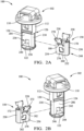
- FIG. 2A is an exploded, perspective view of the blind hole mount fastener 100
- FIG. 2B is an exploded, opposite-side, perspective view of the blind hole mount fastener of FIG. 2A .
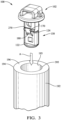
- FIG. 3 is a perspective view of the blind hole mount fastener of FIG. 1 , positioned for insertion into a blind hole.
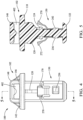
- FIG. 4 is a first end view of the blind hole mount fastener of FIG. 1
- FIG. 5 is a cross-sectional view along lines 5-5 of the blind hole mount fastener of FIG. 4 .
- the blind hole mount fastener 100 is configured to retain an object 190 (e.g., wire, electrical cable, hose, tubing, pipe, fiber optic cable, conduit, wire harness assembly, and bundles thereof) into a bundle and attach the object 190 to a support structure 192 (e.g., framework, mounting surface, mount, vehicle chassis, trailer, bracket, channel, or the like).
- object 190 may include a bundle of objects.
- the blind hole mount fastener 100 is illustrated installed in a bore 194 (e.g., reentrant bore) defined in a support structure 192.
- a bore may be molded, machined, or formed through another suitable process and may have a low-draft angle (e.g., 0.5°).
- the support structure 192 may be configured of any suitable material (e.g., aluminum (e.g., die-cast aluminum), magnesium, another metal, plastic).
- the bore 194 is illustrated as defined in a first side 196 of a boss of the support structure 192.
- a bore may be defined in a planar or other surface of the support structure 192.
- the bore 194 includes at least one wall 193 (e.g., an internal wall).
- the bore 194 is a circular reentrant bore (aka a "blind hole").
- the bore 194 may be a through hole or a slot (e.g., an opening that is generally longer than it is wide (e.g., non-circular bores, slotted holes)) or may have another shape or structure.
- the blind hole mount fastener 100, or elements thereof may have a shape different than is illustrated in the drawings.
- the head portion 110 and the pedestal 122 are illustrated as generally circular (round) in shape. In other aspects, the head portion 110 and/or the pedestal 122 could be another shape (e.g., oval, triangular, square).
- the blind hole mount fastener 100 includes a mount body 102 and a clip member 150.
- the clip member 150 is configured for attaching to the mount body 102.
- the mount body 102 includes a stud portion 112 that is configured for insertion and receipt into the bore 194.
- the mount body 102 also includes a head portion 110 configured to limit the insertion of the stud portion 112 into the bore 194.
- the stud portion 112 may extend downwardly from the head portion 110.
- the head portion 110 may be configured to contact the first side 196 of the support structure 192 when the stud portion 112 is inserted into the bore 194.
- the head portion 110 may include a circumferentially extending cap flange.
- the head portion 110 and the stud portion 112 may be integrally formed through an injection molding process or another suitable process.
- the stud portion 112 has a proximal end 114 and a distal end 116, which define a longitudinal axis (L) therebetween.
- the distal end 116 is located opposite the proximal end 114.
- the stud portion 112 attaches to the head portion 110 at the proximal end 114, with the stud portion 112 extending in a first direction (D) along the longitudinal axis, from the proximal end 114 to the distal end 116.
- the head portion 110 includes a top side 142 opposite a bottom side 144.
- the proximal end 114 of the stud portion 112 extends in the first direction (D) from the bottom side 144 of the head portion 110.
- the distal end 116 of the stud portion 112 may include a pedestal 122.
- the pedestal 122 may extend radially from the stud portion 112.
- the pedestal 122 may be configured as a stop that limits movement of the clip member 150 with respect to the longitudinal axis (L) of the stud portion 112 (e.g., in a longitudinal direction).
- the proximal end 114 of the stud portion 112 may include one or more ribs 120 configured for supporting the stud portion 112 in the bore 194.
- the ribs(s) 120 are sized slightly smaller than an inner diameter of the bore 194.
- the stud portion 112 may further include a limiter 124.
- the limiter 124 extends radially from the stud portion 112 and is located between the pedestal 122 and the head portion 110.
- the limiter 124 may be configured as a stop that limits movement of the clip member 150 with respect to the longitudinal axis (L) of the stud portion 112 (e.g., in a longitudinal direction).
- the limiter 124 is an annular flange.
- the stud portion 112 includes a receiver 126 that is configured to receive the clip member 150.
- the receiver 126 is defined between the pedestal 122 and the limiter 124.
- the pedestal 122 and the limiter 124 axially extend farther from the longitudinal axis of the stud portion 112 than the receiver 126. In this way, the pedestal 122 and the limiter 124 operate as stops that limit movement of the clip member 150 in the longitudinal direction.
- the receiver 126 is configured for receiving the clip member 150 thereon, which enables the clip member 150 to attach to the stud portion 112 at the receiver 126 orthogonal to the first direction (D).
- the clip member 150 has a bottom edge 252 and a top edge 258.
- the bottom edge 252 may be configured to bear against the pedestal 122 and the top edge 258 may be configured to bear against the limiter 124. In this way, the clip member 150 is less likely to unseat off the stud portion 112 and result in the detachment of the bundle from the support structure.
- the receiver 126 is adapted for coupling engagement with the clip member 150.
- the receiver 126 may have a diameter or size less than a diameter or size of the head portion 110.
- the stud portion 112 may have a U-shaped cross-sectional shape.
- the U-shaped cross-sectional shape may include a first planar side 204 that extends in a first plane, an edge portion 210, and a second planar side 206 that extends in a second plane. In the aspect illustrated in FIGs. 1-5 , the first plane and the second plane are generally parallel.
- the edge portion 210 may be curved.
- the clip member 150 is configured for sliding insertion onto the stud portion 112 at the receiver 126 perpendicular to the longitudinal axis (L) of the stud portion 112. In such a configuration, the clip member 150 may be fully captured on the mount body 102 between the head portion 110 and the pedestal 122.
- the clip member 150 is configured to be received within the bore 194 along with the stud portion 112, as illustrated in FIG. 1 and FIG. 3 .
- the bore 194 includes an opening 395.
- the clip member 150 has an arcuate portion 248 that defines a U-shaped cross-sectional shape. In other aspects, the arcuate portion may have another cross-sectional shape.
- the arcuate portion 248 illustrated in the Figures includes a pair of legs (e.g., first leg 254, second leg 256) connected by a seat 250.
- the first leg 254 extends from the seat 250 along a first leg axis and the second leg 256 extends from the seat 250 along a second leg axis.
- the first leg axis and the second leg axis are generally parallel.
- the leg may include a spring arm portion configured for engaging the support structure (e.g., support structure 192) at the bore (e.g., bore 194) and resisting axial withdrawal of the stud portion (e.g., stud portion 112) from the bore.
- a spring arm portion 180 extends from the first leg 254 and a spring arm portion 182 extends from the second leg 256.
- the spring arm portion 180 and spring arm portion 182 are located on opposite sides of the clip member 150.
- the spring arm portion 180 includes a distal end 230 and the spring arm portion 182 includes a distal end 228.
- a distal end may include at least one tooth configured for engaging the bore, for example, by penetrating into a wall of the bore, engaging threading in the bore, and the like.
- Engagement of the bore 194 allows for unidirectional movement of the stud portion 112 into an opening (e.g., opening 395 of FIG. 3 ) of the bore 194 in a first direction (A), illustrated in FIG. 3 , to engage the side wall 193 of the bore 194 and resist movement of the stud portion 112 in an opposite direction.
- a distal end may include one or more teeth.
- the distal end 230 includes two teeth (e.g., tooth 170, tooth 270) and the distal end 228 includes two teeth (e.g., tooth 172, tooth 272).
- the tooth 170 of the spring arm portion 180 and the tooth 172 of the spring arm portion 182 engage the wall 193 of the bore 194.
- a spring arm portion may include a distal end that is angled for engagement with the supporting structure (e.g., with an inside surface of the reentrant bore).
- a spring arm portion (e.g., spring arm portion 180, spring arm portion 182) may extend from the clip member 150 at an angle.
- a spring arm portion may extend at an angle, relative to the longitudinal axis (L), away from a center section of the stud portion 112 when the clip member 150 is in place on the stud portion 112, as illustrated in FIG. 1 .
- the spring arm portions are elongated and configured to allow for low insertion force.
- the clip member 150 may include a first attachment feature configured for engaging a second attachment feature on the stud portion 112 to secure the clip member 150 to the stud portion 112, the attachment features holding the clip member 150 on the stud portion 112 when the stud portion 112 and attached clip member 150 are inserted into the bore 194.
- One or both of the legs may include a first attachment feature.
- both legs include a first attachment feature; namely, an attachment window (e.g., attachment window 260, attachment window 262) is defined in each of the leg 254 and the leg 256.
- the attachment windows are adapted to mechanically engage second attachment features located on the stud portion 112 to secure the clip member 150 to the stud portion 112.
- An attachment window may include a lip (e.g., lip 276 of attachment window 260, lip 278 of attachment window 262) configured for retention on a ledge (e.g., ledge 240, ledge 244) of the second attachment feature.
- the stud portion 112 includes the second attachment feature(s).
- the first planar side 204 of the stud portion 112 includes a snap-fit ramp 236 having a ledge 240 and the second planar side 206 of the stud portion 112 includes a snap-fit ramp 242 having a ledge 244.
- the snap-fit ramp is configured to engage an attachment window defined in the clip member 150.
- FIGs. 2A and 2B the first planar side 204 of the stud portion 112 includes a snap-fit ramp 236 having a ledge 240 and the second planar side 206 of the stud portion 112 includes a snap-fit ramp 242 having a ledge 244.
- the snap-fit ramp is configured to engage an attachment window defined in the clip member 150.
- the snap-fit ramp 236 has an angle face 238 that extends laterally outward from the first planar side 204 to the ledge 240 and the snap-fit ramp 242 has an angle face 246 that extends laterally outward from the second planar side 206 to the ledge 244.
- the clip member 150 is configured to slide onto the stud portion 112 at the receiver 126.
- the lip 276 of the attachment window 260 is deflected outward as the leg (first leg 254, second leg 256) rides down the angle face 238 and the lip 278 of the attachment window 262 is deflected outward as the second leg 256 rides down the angle face 246, with the lips configured to snap over the respective ledges at the end of the snap-fit ramps to form a snap-fit connection.
- the blind hole mount fastener 100 may include a connector section 146 that attaches to the top side 142 of the head portion 110.
- the connector section 146 is configured to connect with an object support 148.
- the object support 148 is configured to support and/or attach to a component (e.g., the object 190).
- the object support 148 may include one or more of a routing component, a clip, a toothed clip, a wire clip, a cable clip, a clamp, cable tie mounts, panel fasteners, a tape bar, a wire channel, saddle mounts, a cable tie saddle, wire harness anchors, a self-affixing clip fastener (e.g., connector clip, bundling clip, harness clip, ratchet P-clamp, C-clip, docking clip, tubing clip, pipe clip, edge clip, routing clip, push pin, ratchet clamps, locking clamps), and the like.
- the object support 148 may also include a moment arm or other structure configured to space an attached bundle apart from the assembly.
- the object support 148 is a cable tie saddle including an aperture (e.g., slot 402) that is configured to interact with and/or adapted to receive a flexible tie (e.g., cable tie) for bundling objects, as illustrated in FIG. 1 .
- a flexible tie e.g., cable tie
- the head portion 110 is configured to provide support for a bundle while the tie is secured to the assembly through the slot 402.
- the object support 148 includes the slot 402 arranged to receive a fastener (e.g., cable tie 198).
- the cable tie 198 is illustrated in dotted-line fashion as securing the object 190 to the object support 148.
- the object support 148 may attach to the object 190 via a fastener.
- the object support 148 is illustrated attached to the object 190 via the cable tie 198.
- a cable tie may include a strap (e.g., tie tail) and a tie head.
- the cable tie 198 may be used to wrap and secure a bundle and may be used to secure the bundle to the object support 148.
- the cable tie 198 may be integrally formed with the object support 148 or may be a separate piece. In other aspects, another fastener may be utilized in lieu of a cable tie.
- the blind hole mount fastener 100 may include a spring section 164 extending downwardly from the head portion 110, the spring section 164 configured to provide tension and resistance when the stud portion 112 is inserted into an opening defined in the supporting surface.
- the spring section 164 may taper downwardly and outwardly from a first end located at the head portion 110 to a second end.
- a spring section may be circular, cylindrical, or another shape that will provide the necessary resistance for the spring section.
- the spring section 164 may be configured to contact the first side 196 of the support structure 192 and may be located below or incorporated as part of the head portion 110 of the blind hole mount fastener 100. In such a configuration, the stud portion 112 may extend downwardly from the head portion 110 and/or the spring section 164.
- the mount body (e.g., mount body 102) may be formed of a polymer.
- suitable polymers for the blind hole mount fasteners disclosed herein include, but are not limited to, nylon, polyamide (PA), PA12, PA46, PA66, PA66HS, PA66UV, OUV, PA66VO, PA66HIRHS, PA66HIRHSUV, polypropylene (PP), polyethylene (PE), polyphenylene sulfide (PPS), polyether ether ketone (PEEK), polyaryletherketone (PAEK), ethylene tetrafluoroethylene (ETFE), polyacetal (POM), polybutylene terephthalate (PBT), ultraviolet (UV) stabilized polyacetal (POMUV), thermoplastic materials, higher-temperature resins, UV resistant resins, and the like, and copolymers, blends, or alloys thereof.
- the polymer may be glass-fiber reinforced.
- the polymer may include one or more additives (e.g., heat stabilizers (e.g., copper iodide), impact modifiers (e.g., polyolefin, urethane, rubber), UV stabilizers (e.g., carbon black, hindered amine light stabilizers (HALS)), flame retardants (e.g., nitrogen-based halogen-free flame retardants, melamine cyanurate, melamine borate, ammonium polyphosphate), colorants, and the like).
- additives e.g., heat stabilizers (e.g., copper iodide), impact modifiers (e.g., polyolefin, urethane, rubber), UV stabilizers (e.g., carbon black, hindered amine light stabilizers (HALS)), flame retardants (e.g., nitrogen-based halogen-free flame retardants, melamine cyanurate, melamine borate,
- the clip member (e.g., clip member 150) may be fabricated of any rigid metal sufficient to withstand pull-out force (e.g., aluminum, spring steel).
- blind hole mount fasteners are as follows:
- blind hole mount fasteners have been described in language specific to certain features and/or methods, the subject of the appended claims is not necessarily limited to the specific features or methods described. Rather, the specific features and methods are disclosed as example implementations for blind hole mount fasteners.
- a, b, or c can cover a, b, c, a-b, a-c, b-c, and a-b-c, as well as any combination with multiples of the same element (e.g., a-a, a-a-a, a-a-b, a-a-c, a-b-b, a-c-c, b-b, b-b-b, b-b-c, c-c, and c-c-c, or any other ordering of a, b, and c).
- items represented in the accompanying figures and terms discussed herein may be indicative of one or more items or terms, and thus reference may be made interchangeably to single or plural forms of the items and terms in this written description.
Landscapes
- Engineering & Computer Science (AREA)
- General Engineering & Computer Science (AREA)
- Mechanical Engineering (AREA)
- Architecture (AREA)
- Civil Engineering (AREA)
- Structural Engineering (AREA)
- Insertion Pins And Rivets (AREA)
- Connection Of Plates (AREA)
- Clamps And Clips (AREA)
Abstract
Description
- This application claims the benefit of
U.S. Provisional Application Nos. 63/584,442, filed September 21, 2023 63/509,706, filed June 22, 2023 - A mounting assembly can be utilized to secure one or more objects (e.g., wire, electrical cable, hose, tubing, pipe, fiber optic cable, conduit, wire harness assembly, and bundles thereof) together into a bundle. In many applications, it is sufficient merely to secure objects into a bundle. Such applications might include, for example, stationary electronic equipment that remains in one place and is subject to little or no vibration in use. In other applications, it is desirable not only to secure objects into a bundle but also to secure the resulting bundle to a support structure (e.g., framework, mounting surface, mount, vehicle chassis, trailer, bracket, channel, or the like). Such applications are common, for example, in automobiles, airplanes, ships, boats, and other vehicles where the bundle is likely to be subjected to severe jostling and vibration. In other applications (e.g., buildings), where vibration might not be an important consideration, it may still be desirable to secure and route objects to a support structure.
- A support structure may include a surface that defines a bore (e.g., blind hole, reentrant bore, through bore, opening, orifice, aperture, slot, and the like) that may permit attachment of a bundle to the support structure. A bore may be threaded. One type of a mounting assembly that may be used to secure a bundle to a bore of a support structure is a blind hole mount fastener. A blind hole mount fastener may include a mount member and a clip member, the mount member having a head portion and a stud portion extending downwardly from the head portion and the clip member configured to be affixed to the stud portion of the mount member.
- Existing blind hole mount fasteners may not provide efficient, secure retention features that provide a robust grip when applied in a reentrant bore and may not provide sufficient retention and tightness against the surface of the support structure for adequately supporting a bundled object, and the clip member may separate from the stud portion of the fastener, resulting in the detachment of the bundle from the support structure.
- This disclosure relates generally to hardware for securing bundled objects, such as wires, cables, hoses, tubing, fiber optics, conduits, vines, etc., to a support structure (e.g., to a side of the support structure via a bore). Disclosed are aspects of blind hole mount fasteners that include a mount body and an attached clip member configured for securing the bundled objects to a support structure having a side defining a bore (e.g., blind hole, reentrant bore, through bore).
- In some aspects, the techniques described herein relate to a blind hole mount fastener configured to retain an object to a support structure defining a bore, the blind hole mount fastener including: a mount body including: a stud portion configured to be received within the bore, the stud portion including a proximal end and a distal end, the stud portion defining a longitudinal axis between the proximal end and the distal end, the stud portion extending in a first direction from the proximal end to the distal end, the stud portion including a receiver; and a head portion configured to limit an insertion of the stud portion into the bore, the head portion attaching to the stud portion at the proximal end; and a clip member attached to the stud portion orthogonally to the first direction, the clip member attached to the stud portion at the receiver, the clip member configured to be received within the bore with the stud portion, the clip member defining an arcuate portion and at least one spring arm portion extending from the clip member.
- This Summary is provided to introduce simplified concepts of blind hole mount fasteners, which are further described below in the Detailed Description and are illustrated in the Drawings. This Summary is not intended to identify essential features of the claimed subject matter, nor is it intended for use in determining the scope of the claimed subject matter.
- The details of one or more aspects of blind hole mount fasteners are described with reference to the following Drawings, in which the use of the same numbers in different instances may indicate like features and/or components.
-
FIG. 1 is an environmental first side view of a blind hole mount fastener. -
FIG. 2A is an exploded, perspective view of the blind hole mount fastener ofFIG. 1 . -
FIG. 2B is an exploded, opposite-side, perspective view of the blind hole mount fastener ofFIG. 2A . -
FIG. 3 is a perspective view of the blind hole mount fastener ofFIG. 1 , positioned for insertion into a blind hole. -
FIG. 4 is a first end view of the blind hole mount fastener ofFIG. 1 . -
FIG. 5 is a cross-sectional view along lines 5-5 of the blind hole mount fastener ofFIG. 4 . - This document describes, and the drawings illustrate, blind hole mount fasteners configured to retain an object to a support structure defining a bore (e.g., reentrant bore). In a general aspect, a blind hole mount fastener includes a mount body and a clip member. The mount body includes a head portion and a stud portion. The stud portion may extend downwardly from the head portion. The stud portion is configured for insertion into the bore and the head portion is configured to limit the insertion of the stud portion into the bore. The stud portion has a proximal end and a distal end, which define a longitudinal axis therebetween. The stud portion extends in a first direction along the longitudinal axis. The stud portion includes a receiver that is configured for receiving the clip member thereon, which enables the clip member to attach to the stud portion at the receiver orthogonal to the first direction. The clip member is configured to be received within the bore with the stud portion. In this way, the clip member is secured to the stud portion, decreasing the chances that the clip member will separate from the stud portion and result in detachment of the bundle from the support structure.
- The disclosed mounting assemblies may be configured to allow the clip member and the mount body to work together to resist axial extraction of the blind hole mount fastener from the bore.
- Described herein and illustrated in the Drawings are aspects of blind hole mount fasteners. A blind hole mount fastener according to this disclosure may include any combination of one or more of the following features. Optional features of one aspect described herein may be combined with other aspects to form further aspects.
-
FIGs. 1-5 illustrate a first example of a blindhole mount fastener 100.FIG. 1 is an environmental view of the blindhole mount fastener 100 and illustrates a first side of the blindhole mount fastener 100.FIG. 2A is an exploded, perspective view of the blind hole mount fastener 100, andFIG. 2B is an exploded, opposite-side, perspective view of the blind hole mount fastener ofFIG. 2A .FIG. 3 is a perspective view of the blind hole mount fastener ofFIG. 1 , positioned for insertion into a blind hole.FIG. 4 is a first end view of the blind hole mount fastener ofFIG. 1 , andFIG. 5 is a cross-sectional view along lines 5-5 of the blind hole mount fastener ofFIG. 4 . - The blind
hole mount fastener 100 is configured to retain an object 190 (e.g., wire, electrical cable, hose, tubing, pipe, fiber optic cable, conduit, wire harness assembly, and bundles thereof) into a bundle and attach theobject 190 to a support structure 192 (e.g., framework, mounting surface, mount, vehicle chassis, trailer, bracket, channel, or the like). Theobject 190 may include a bundle of objects. - The blind
hole mount fastener 100 is illustrated installed in a bore 194 (e.g., reentrant bore) defined in asupport structure 192. A bore may be molded, machined, or formed through another suitable process and may have a low-draft angle (e.g., 0.5°). Thesupport structure 192 may be configured of any suitable material (e.g., aluminum (e.g., die-cast aluminum), magnesium, another metal, plastic). InFIG. 1 andFIG. 3 , thebore 194 is illustrated as defined in afirst side 196 of a boss of thesupport structure 192. In other aspects, a bore may be defined in a planar or other surface of thesupport structure 192. Thebore 194 includes at least one wall 193 (e.g., an internal wall). In the aspect illustrated inFIGs. 1 and3 , thebore 194 is a circular reentrant bore (aka a "blind hole"). In other aspects, thebore 194 may be a through hole or a slot (e.g., an opening that is generally longer than it is wide (e.g., non-circular bores, slotted holes)) or may have another shape or structure. Likewise, the blindhole mount fastener 100, or elements thereof, may have a shape different than is illustrated in the drawings. For example, inFIGs. 1-3 , thehead portion 110 and thepedestal 122 are illustrated as generally circular (round) in shape. In other aspects, thehead portion 110 and/or thepedestal 122 could be another shape (e.g., oval, triangular, square). - The blind
hole mount fastener 100 includes amount body 102 and aclip member 150. Theclip member 150 is configured for attaching to themount body 102. Themount body 102 includes astud portion 112 that is configured for insertion and receipt into thebore 194. Themount body 102 also includes ahead portion 110 configured to limit the insertion of thestud portion 112 into thebore 194. Thestud portion 112 may extend downwardly from thehead portion 110. Thehead portion 110 may be configured to contact thefirst side 196 of thesupport structure 192 when thestud portion 112 is inserted into thebore 194. Thehead portion 110 may include a circumferentially extending cap flange. Thehead portion 110 and thestud portion 112 may be integrally formed through an injection molding process or another suitable process. - The
stud portion 112 has aproximal end 114 and adistal end 116, which define a longitudinal axis (L) therebetween. Thedistal end 116 is located opposite theproximal end 114. Thestud portion 112 attaches to thehead portion 110 at theproximal end 114, with thestud portion 112 extending in a first direction (D) along the longitudinal axis, from theproximal end 114 to thedistal end 116. Thehead portion 110 includes atop side 142 opposite abottom side 144. Theproximal end 114 of thestud portion 112 extends in the first direction (D) from thebottom side 144 of thehead portion 110. - The
distal end 116 of thestud portion 112 may include apedestal 122. Thepedestal 122 may extend radially from thestud portion 112. Thepedestal 122 may be configured as a stop that limits movement of theclip member 150 with respect to the longitudinal axis (L) of the stud portion 112 (e.g., in a longitudinal direction). Theproximal end 114 of thestud portion 112 may include one ormore ribs 120 configured for supporting thestud portion 112 in thebore 194. In aspects, the ribs(s) 120 are sized slightly smaller than an inner diameter of thebore 194. - The
stud portion 112 may further include alimiter 124. In aspects, thelimiter 124 extends radially from thestud portion 112 and is located between thepedestal 122 and thehead portion 110. Thelimiter 124 may be configured as a stop that limits movement of theclip member 150 with respect to the longitudinal axis (L) of the stud portion 112 (e.g., in a longitudinal direction). In the aspect illustrated inFIGs. 1-5 , thelimiter 124 is an annular flange. - The
stud portion 112 includes areceiver 126 that is configured to receive theclip member 150. Thereceiver 126 is defined between thepedestal 122 and thelimiter 124. In the aspect illustrated inFIGs. 1-5 , thepedestal 122 and thelimiter 124 axially extend farther from the longitudinal axis of thestud portion 112 than thereceiver 126. In this way, thepedestal 122 and thelimiter 124 operate as stops that limit movement of theclip member 150 in the longitudinal direction. - The
receiver 126 is configured for receiving theclip member 150 thereon, which enables theclip member 150 to attach to thestud portion 112 at thereceiver 126 orthogonal to the first direction (D). Theclip member 150 has abottom edge 252 and atop edge 258. Thebottom edge 252 may be configured to bear against thepedestal 122 and thetop edge 258 may be configured to bear against thelimiter 124. In this way, theclip member 150 is less likely to unseat off thestud portion 112 and result in the detachment of the bundle from the support structure. - The
receiver 126 is adapted for coupling engagement with theclip member 150. Thereceiver 126 may have a diameter or size less than a diameter or size of thehead portion 110. At thereceiver 126, thestud portion 112 may have a U-shaped cross-sectional shape. The U-shaped cross-sectional shape may include a firstplanar side 204 that extends in a first plane, anedge portion 210, and a secondplanar side 206 that extends in a second plane. In the aspect illustrated inFIGs. 1-5 , the first plane and the second plane are generally parallel. Theedge portion 210 may be curved. - In aspects, the
clip member 150 is configured for sliding insertion onto thestud portion 112 at thereceiver 126 perpendicular to the longitudinal axis (L) of thestud portion 112. In such a configuration, theclip member 150 may be fully captured on themount body 102 between thehead portion 110 and thepedestal 122. Theclip member 150 is configured to be received within thebore 194 along with thestud portion 112, as illustrated inFIG. 1 andFIG. 3 . Thebore 194 includes anopening 395. - In the aspect illustrated in
FIGs. 1-5 , theclip member 150 has anarcuate portion 248 that defines a U-shaped cross-sectional shape. In other aspects, the arcuate portion may have another cross-sectional shape. Thearcuate portion 248 illustrated in the Figures includes a pair of legs (e.g.,first leg 254, second leg 256) connected by aseat 250. Thefirst leg 254 extends from theseat 250 along a first leg axis and thesecond leg 256 extends from theseat 250 along a second leg axis. In the aspect illustrated inFIGs. 1-5 , the first leg axis and the second leg axis are generally parallel. - The leg (e.g.,
first leg 254, second leg 256) may include a spring arm portion configured for engaging the support structure (e.g., support structure 192) at the bore (e.g., bore 194) and resisting axial withdrawal of the stud portion (e.g., stud portion 112) from the bore. In the aspect illustrated inFIGs. 1-5 , aspring arm portion 180 extends from thefirst leg 254 and aspring arm portion 182 extends from thesecond leg 256. In this aspect, thespring arm portion 180 andspring arm portion 182 are located on opposite sides of theclip member 150. - In the aspect illustrated in
FIGs. 1-5 , thespring arm portion 180 includes adistal end 230 and thespring arm portion 182 includes adistal end 228. A distal end may include at least one tooth configured for engaging the bore, for example, by penetrating into a wall of the bore, engaging threading in the bore, and the like. Engagement of thebore 194 allows for unidirectional movement of thestud portion 112 into an opening (e.g., opening 395 ofFIG. 3 ) of thebore 194 in a first direction (A), illustrated inFIG. 3 , to engage theside wall 193 of thebore 194 and resist movement of thestud portion 112 in an opposite direction. - A distal end may include one or more teeth. In the aspect illustrated in
FIGs. 1-5 , thedistal end 230 includes two teeth (e.g.,tooth 170, tooth 270) and thedistal end 228 includes two teeth (e.g.,tooth 172, tooth 272). In the aspect illustrated inFIG. 1 , thetooth 170 of thespring arm portion 180 and thetooth 172 of thespring arm portion 182 engage thewall 193 of thebore 194. - A spring arm portion may include a distal end that is angled for engagement with the supporting structure (e.g., with an inside surface of the reentrant bore). A spring arm portion (e.g.,
spring arm portion 180, spring arm portion 182) may extend from theclip member 150 at an angle. For example, a spring arm portion may extend at an angle, relative to the longitudinal axis (L), away from a center section of thestud portion 112 when theclip member 150 is in place on thestud portion 112, as illustrated inFIG. 1 . In aspects, the spring arm portions are elongated and configured to allow for low insertion force. - The
clip member 150 may include a first attachment feature configured for engaging a second attachment feature on thestud portion 112 to secure theclip member 150 to thestud portion 112, the attachment features holding theclip member 150 on thestud portion 112 when thestud portion 112 and attachedclip member 150 are inserted into thebore 194. One or both of the legs (e.g.,leg 254, leg 256) may include a first attachment feature. In the aspect illustrated in the Figures, both legs include a first attachment feature; namely, an attachment window (e.g.,attachment window 260, attachment window 262) is defined in each of theleg 254 and theleg 256. The attachment windows are adapted to mechanically engage second attachment features located on thestud portion 112 to secure theclip member 150 to thestud portion 112. An attachment window may include a lip (e.g.,lip 276 ofattachment window 260,lip 278 of attachment window 262) configured for retention on a ledge (e.g.,ledge 240, ledge 244) of the second attachment feature. - In the aspect illustrated in the drawings, the
stud portion 112 includes the second attachment feature(s). For example, inFIGs. 2A and 2B , the firstplanar side 204 of thestud portion 112 includes a snap-fit ramp 236 having aledge 240 and the secondplanar side 206 of thestud portion 112 includes a snap-fit ramp 242 having aledge 244. The snap-fit ramp is configured to engage an attachment window defined in theclip member 150. In the aspect illustrated inFIGs. 2A and 2B , the snap-fit ramp 236 has anangle face 238 that extends laterally outward from the firstplanar side 204 to theledge 240 and the snap-fit ramp 242 has anangle face 246 that extends laterally outward from the secondplanar side 206 to theledge 244. Theclip member 150 is configured to slide onto thestud portion 112 at thereceiver 126. When theclip member 150 is slid onto thereceiver 126, thelip 276 of theattachment window 260 is deflected outward as the leg (first leg 254, second leg 256) rides down theangle face 238 and thelip 278 of theattachment window 262 is deflected outward as thesecond leg 256 rides down theangle face 246, with the lips configured to snap over the respective ledges at the end of the snap-fit ramps to form a snap-fit connection. - In aspects, the blind
hole mount fastener 100 may include aconnector section 146 that attaches to thetop side 142 of thehead portion 110. Theconnector section 146 is configured to connect with anobject support 148. Theobject support 148 is configured to support and/or attach to a component (e.g., the object 190). Theobject support 148 may include one or more of a routing component, a clip, a toothed clip, a wire clip, a cable clip, a clamp, cable tie mounts, panel fasteners, a tape bar, a wire channel, saddle mounts, a cable tie saddle, wire harness anchors, a self-affixing clip fastener (e.g., connector clip, bundling clip, harness clip, ratchet P-clamp, C-clip, docking clip, tubing clip, pipe clip, edge clip, routing clip, push pin, ratchet clamps, locking clamps), and the like. Theobject support 148 may also include a moment arm or other structure configured to space an attached bundle apart from the assembly. In the aspect illustrated in the Figures, theobject support 148 is a cable tie saddle including an aperture (e.g., slot 402) that is configured to interact with and/or adapted to receive a flexible tie (e.g., cable tie) for bundling objects, as illustrated inFIG. 1 . In such a configuration, thehead portion 110 is configured to provide support for a bundle while the tie is secured to the assembly through theslot 402. In the aspect illustrated inFIGs. 1-5 , theobject support 148 includes theslot 402 arranged to receive a fastener (e.g., cable tie 198). InFIG. 1 , thecable tie 198 is illustrated in dotted-line fashion as securing theobject 190 to theobject support 148. - The
object support 148 may attach to theobject 190 via a fastener. InFIG. 1 , theobject support 148 is illustrated attached to theobject 190 via thecable tie 198. A cable tie may include a strap (e.g., tie tail) and a tie head. Thecable tie 198 may be used to wrap and secure a bundle and may be used to secure the bundle to theobject support 148. Thecable tie 198 may be integrally formed with theobject support 148 or may be a separate piece. In other aspects, another fastener may be utilized in lieu of a cable tie. - In aspects, the blind
hole mount fastener 100 may include aspring section 164 extending downwardly from thehead portion 110, thespring section 164 configured to provide tension and resistance when thestud portion 112 is inserted into an opening defined in the supporting surface. Thespring section 164 may taper downwardly and outwardly from a first end located at thehead portion 110 to a second end. A spring section may be circular, cylindrical, or another shape that will provide the necessary resistance for the spring section. Thespring section 164 may be configured to contact thefirst side 196 of thesupport structure 192 and may be located below or incorporated as part of thehead portion 110 of the blindhole mount fastener 100. In such a configuration, thestud portion 112 may extend downwardly from thehead portion 110 and/or thespring section 164. - The mount body (e.g., mount body 102) may be formed of a polymer. Examples of suitable polymers for the blind hole mount fasteners disclosed herein include, but are not limited to, nylon, polyamide (PA), PA12, PA46, PA66, PA66HS, PA66UV, OUV, PA66VO, PA66HIRHS, PA66HIRHSUV, polypropylene (PP), polyethylene (PE), polyphenylene sulfide (PPS), polyether ether ketone (PEEK), polyaryletherketone (PAEK), ethylene tetrafluoroethylene (ETFE), polyacetal (POM), polybutylene terephthalate (PBT), ultraviolet (UV) stabilized polyacetal (POMUV), thermoplastic materials, higher-temperature resins, UV resistant resins, and the like, and copolymers, blends, or alloys thereof. The polymer may be glass-fiber reinforced. The polymer may include one or more additives (e.g., heat stabilizers (e.g., copper iodide), impact modifiers (e.g., polyolefin, urethane, rubber), UV stabilizers (e.g., carbon black, hindered amine light stabilizers (HALS)), flame retardants (e.g., nitrogen-based halogen-free flame retardants, melamine cyanurate, melamine borate, ammonium polyphosphate), colorants, and the like).
- The clip member (e.g., clip member 150) may be fabricated of any rigid metal sufficient to withstand pull-out force (e.g., aluminum, spring steel).
- Some additional examples of blind hole mount fasteners are as follows:
- Example 1. A blind hole mount fastener configured to retain an object to a support structure defining a bore, the blind hole mount fastener comprising: a mount body comprising: a stud portion configured to be received within the bore, the stud portion including a proximal end and a distal end, the stud portion defining a longitudinal axis between the proximal end and the distal end, the stud portion extending in a first direction from the proximal end to the distal end, the stud portion including a receiver; and a head portion configured to limit an insertion of the stud portion into the bore, the head portion attaching to the stud portion at the proximal end; and a clip member attached to the stud portion orthogonally to the first direction, the clip member attached to the stud portion at the receiver, the clip member configured to be received within the bore with the stud portion, the clip member defining an arcuate portion and at least one spring arm portion extending from the clip member.
- Example 2. The blind hole mount fastener of Example 1, wherein the distal end of the stud portion comprises: a pedestal that extends from the stud portion.
- Example 3. The blind hole mount fastener of Example 2, wherein the stud portion further comprises: a limiter that extends from the stud portion.
- Example 4. The blind hole mount fastener of Example 3, wherein the stud portion defines the receiver configured for receiving the clip member, the receiver defined between the pedestal and the limiter, the pedestal and the limiter configured to operate as stops that limit movement of the clip member with respect to the longitudinal axis.
- Example 5. The blind hole mount fastener of Example 4, wherein the spring arm portion comprises a distal end including at least one tooth configured to penetrate into a wall of the bore.
- Example 6. The blind hole mount fastener of Example 1, wherein the spring arm portion comprises a distal end including at least one tooth configured to penetrate into a wall of the bore.
- Example 7. The blind hole mount fastener of Example 1, wherein the arcuate portion further comprises: a seat; and a pair of legs extending from the seat, wherein the pair of legs extend from the clip member at an angle relative to the longitudinal axis.
- Example 8. The blind hole mount fastener of Example 1, wherein the stud portion has a U-shaped cross-sectional shape having a first planar side extending in the first direction, a curved edge portion, and a second planar side extending in a second direction, the first direction and the second direction generally parallel.
- Example 9. The blind hole mount fastener of Example 8, wherein at least one of the first planar side or the second planar side includes a snap-fit ramp configured for engaging an attachment window defined in the clip member.
- Example 10. The blind hole mount fastener of Example 9, wherein the snap-fit ramp has an angle face that extends laterally outward from one of the first or second planar sides.
- Example 11. The blind hole mount fastener of Example 10, wherein the arcuate portion further comprises: a seat; and a pair of legs extending from the seat, wherein the pair of legs extend from the clip member at an angle, and wherein an inwardly projecting lip of the attachment window is deflected outward as the leg rides down the snap-fit ramp, the lip configured for snapping over a ledge at an end of the snap-fit ramp to form a snap-fit connection.
- Example 12. The blind hole mount fastener of Example 1, wherein the head portion further comprises a top side opposite a bottom side, the proximal end of the stud portion extending in the first direction from the bottom side of the head portion.
- Example 13. The blind hole mount fastener of Example 12, further comprising: a connector section attaching to the top side of the head portion, the connector section configured for connecting with an object support configured for attaching to an object.
- Example 14. The blind hole mount fastener of Example 13, wherein the object support comprises a slot arranged to receive a cable tie and the connector section is configured to support the object while the cable tie is secured through the slot.
- Example 15. The blind hole mount fastener of Example 1, further comprising: a spring section attaching to a bottom side of the head portion, the spring section configured to contact a first side of the support structure and limit the insertion of the stud portion into the bore.
- Example 16. The blind hole mount fastener of Example 1, further comprising: an object support connected to a top side of the head portion, the object support configured for supporting the object.
- Example 17. The blind hole mount fastener of Example 16, wherein the object support further comprises: a slot arranged to receive a cable tie, wherein the object support is configured to support a bundle while the cable tie is secured through the slot.
- Example 18. The blind hole mount fastener of Example 1, wherein the mount body is formed of a polymer material.
- Example 19. The blind hole mount fastener of Example 18, wherein the head portion and the stud portion are integrally formed through an injection molding process.
- Example 20. The blind hole mount fastener of Example 1, wherein the clip member is formed of a metallic material.
- Although implementations for blind hole mount fasteners have been described in language specific to certain features and/or methods, the subject of the appended claims is not necessarily limited to the specific features or methods described. Rather, the specific features and methods are disclosed as example implementations for blind hole mount fasteners.
- Unless context dictates otherwise, use herein of the word "or" may be considered use of an "inclusive or," or a term that permits inclusion or application of one or more items that are linked by the word "or" (e.g., a phrase "A or B" may be interpreted as permitting just "A," as permitting just "B," or as permitting both "A" and "B"). Also, as used herein, a phrase referring to "at least one of" a list of items refers to any combination of those items, including single members. For instance, "at least one of a, b, or c" can cover a, b, c, a-b, a-c, b-c, and a-b-c, as well as any combination with multiples of the same element (e.g., a-a, a-a-a, a-a-b, a-a-c, a-b-b, a-c-c, b-b, b-b-b, b-b-c, c-c, and c-c-c, or any other ordering of a, b, and c). Further, items represented in the accompanying figures and terms discussed herein may be indicative of one or more items or terms, and thus reference may be made interchangeably to single or plural forms of the items and terms in this written description.
Claims (15)
- A blind hole mount fastener configured to retain an object to a support structure defining a bore, the blind hole mount fastener comprising:a mount body comprising:a stud portion configured to be received within the bore, the stud portion including a proximal end and a distal end, the stud portion defining a longitudinal axis between the proximal end and the distal end, the stud portion extending in a first direction from the proximal end to the distal end, the stud portion including a receiver; anda head portion configured to limit an insertion of the stud portion into the bore, the head portion attaching to the stud portion at the proximal end; anda clip member attached to the stud portion orthogonally to the first direction, the clip member attached to the stud portion at the receiver, the clip member configured to be received within the bore with the stud portion, the clip member defining an arcuate portion and at least one spring arm portion extending from the clip member.
- The blind hole mount fastener of claim 1, wherein the distal end of the stud portion comprises:
a pedestal that extends from the stud portion. - The blind hole mount fastener of any one of the preceding claims, wherein the stud portion further comprises:
a limiter that extends from the stud portion. - The blind hole mount fastener of claims 2 and 3, wherein the stud portion defines the receiver configured for receiving the clip member, the receiver defined between the pedestal and the limiter, the pedestal and the limiter configured to operate as stops that limit movement of the clip member with respect to the longitudinal axis.
- The blind hole mount fastener of any one of the preceding claims, wherein the spring arm portion comprises a distal end including at least one tooth configured to penetrate into a wall of the bore.
- The blind hole mount fastener of any one of the preceding claims, wherein the arcuate portion further comprises:a seat; anda pair of legs extending from the seat,wherein the pair of legs extend from the clip member at an angle relative to the longitudinal axis.
- The blind hole mount fastener of any one of the preceding claims, wherein the stud portion has a U-shaped cross-sectional shape having a first planar side extending in the first direction, a curved edge portion, and a second planar side extending in a second direction, the first direction and the second direction generally parallel.
- The blind hole mount fastener of claim 7, wherein at least one of the first planar side or the second planar side includes a snap-fit ramp configured for engaging an attachment window defined in the clip member.
- The blind hole mount fastener of claim 8, wherein the snap-fit ramp has an angle face that extends laterally outward from one of the first or second planar sides.
- The blind hole mount fastener of claim 6 and any one of the claims 8 to 9,
wherein an inwardly projecting lip of the attachment window is deflected outward as the leg rides down the snap-fit ramp, the lip configured for snapping over a ledge at an end of the snap-fit ramp to form a snap-fit connection. - The blind hole mount fastener of any one of the preceding claims, wherein the head portion further comprises a top side opposite a bottom side, the proximal end of the stud portion extending in the first direction from the bottom side of the head portion.
- The blind hole mount fastener of claim 11, further comprising:
a connector section attaching to the top side of the head portion, the connector section configured for connecting with an object support configured for attaching to an object. - The blind hole mount fastener of any one of the preceding claims, further comprising:
an object support connected to a top side of the head portion, the object support configured for supporting the object. - The blind hole mount fastener of claim 12 or 13, wherein the object support comprises a slot arranged to receive a cable tie and the connector section is configured to support the object while the cable tie is secured through the slot.
- The blind hole mount fastener of any one of the preceding claims, further comprising:
a spring section attaching to a bottom side of the head portion, the spring section configured to contact a first side of the support structure and limit the insertion of the stud portion into the bore.
Applications Claiming Priority (3)
| Application Number | Priority Date | Filing Date | Title |
|---|---|---|---|
| US202363509706P | 2023-06-22 | 2023-06-22 | |
| US202363584442P | 2023-09-21 | 2023-09-21 | |
| US18/738,794 US20240426420A1 (en) | 2023-06-22 | 2024-06-10 | Mounting Assemblies |
Publications (2)
| Publication Number | Publication Date |
|---|---|
| EP4481211A1 true EP4481211A1 (en) | 2024-12-25 |
| EP4481211B1 EP4481211B1 (en) | 2026-03-04 |
Family
ID=91620553
Family Applications (1)
| Application Number | Title | Priority Date | Filing Date |
|---|---|---|---|
| EP24183333.4A Active EP4481211B1 (en) | 2023-06-22 | 2024-06-20 | Mounting assemblies |
Country Status (3)
| Country | Link |
|---|---|
| US (1) | US20240426420A1 (en) |
| EP (1) | EP4481211B1 (en) |
| CN (1) | CN119176091A (en) |
Families Citing this family (1)
| Publication number | Priority date | Publication date | Assignee | Title |
|---|---|---|---|---|
| US12338848B2 (en) | 2022-06-30 | 2025-06-24 | Hellermanntyton Corporation | Anti-wobble fir tree mount |
Citations (2)
| Publication number | Priority date | Publication date | Assignee | Title |
|---|---|---|---|---|
| US20170059060A1 (en) * | 2015-08-25 | 2017-03-02 | Hellermanntyton Corporation | Blind hole mount |
| DE102020120438A1 (en) * | 2020-08-03 | 2022-02-03 | Illinois Tool Works Inc. | hole fastening system |
-
2024
- 2024-06-10 US US18/738,794 patent/US20240426420A1/en active Pending
- 2024-06-20 EP EP24183333.4A patent/EP4481211B1/en active Active
- 2024-06-21 CN CN202410808574.5A patent/CN119176091A/en active Pending
Patent Citations (2)
| Publication number | Priority date | Publication date | Assignee | Title |
|---|---|---|---|---|
| US20170059060A1 (en) * | 2015-08-25 | 2017-03-02 | Hellermanntyton Corporation | Blind hole mount |
| DE102020120438A1 (en) * | 2020-08-03 | 2022-02-03 | Illinois Tool Works Inc. | hole fastening system |
Also Published As
| Publication number | Publication date |
|---|---|
| EP4481211B1 (en) | 2026-03-04 |
| CN119176091A (en) | 2024-12-24 |
| US20240426420A1 (en) | 2024-12-26 |
Similar Documents
| Publication | Publication Date | Title |
|---|---|---|
| US10119631B2 (en) | Adjustable p-clamp | |
| US8991774B2 (en) | Cable tie mount | |
| JP6602956B2 (en) | Blind hole mount | |
| US20070102594A1 (en) | Flush mount connector clip | |
| US10323774B2 (en) | Mounting device with self-centering support surface | |
| US6508442B1 (en) | Mounting clamp for a tubular part | |
| US12460749B2 (en) | Cradle mount fixings | |
| US7497718B2 (en) | Routing clip elements with a living hinge and interlocking closure | |
| US10723291B2 (en) | Holding clamp for holding vehicle parts in a vehicle | |
| US7819365B2 (en) | Fastening device for cables | |
| EP4481211B1 (en) | Mounting assemblies | |
| EP4538545A1 (en) | Snap-on bracket clamp assemblies | |
| EP4299928A1 (en) | Anti-wobble fir tree mount | |
| US12326210B2 (en) | Quick attach clamp | |
| US20240360856A1 (en) | Fixings with Cutting Guides | |
| JP2009270686A (en) | Wiring member holder | |
| CN103282239A (en) | Conduit for receiving elongate elements, method for mounting same, and assembly comprising a mounting and such a conduit | |
| WO2009039270A1 (en) | Band clamp for elongated member | |
| US12631206B2 (en) | Twist-lock fixings | |
| US20250350103A1 (en) | Transition Fixing | |
| EP4350188A1 (en) | Clip | |
| EP4648237A1 (en) | Wire rail systems | |
| DE102017105084A1 (en) | Tube holder |
Legal Events
| Date | Code | Title | Description |
|---|---|---|---|
| PUAI | Public reference made under article 153(3) epc to a published international application that has entered the european phase |
Free format text: ORIGINAL CODE: 0009012 |
|
| STAA | Information on the status of an ep patent application or granted ep patent |
Free format text: STATUS: THE APPLICATION HAS BEEN PUBLISHED |
|
| AK | Designated contracting states |
Kind code of ref document: A1 Designated state(s): AL AT BE BG CH CY CZ DE DK EE ES FI FR GB GR HR HU IE IS IT LI LT LU LV MC ME MK MT NL NO PL PT RO RS SE SI SK SM TR |
|
| STAA | Information on the status of an ep patent application or granted ep patent |
Free format text: STATUS: REQUEST FOR EXAMINATION WAS MADE |
|
| 17P | Request for examination filed |
Effective date: 20250505 |
|
| GRAP | Despatch of communication of intention to grant a patent |
Free format text: ORIGINAL CODE: EPIDOSNIGR1 |
|
| STAA | Information on the status of an ep patent application or granted ep patent |
Free format text: STATUS: GRANT OF PATENT IS INTENDED |
|
| RIC1 | Information provided on ipc code assigned before grant |
Ipc: F16B 21/08 20060101AFI20251104BHEP Ipc: F16B 2/24 20060101ALN20251104BHEP Ipc: F16B 13/04 20060101ALN20251104BHEP |
|
| RIC1 | Information provided on ipc code assigned before grant |
Ipc: F16B 21/08 20060101AFI20251113BHEP Ipc: F16B 2/24 20060101ALN20251113BHEP Ipc: F16B 13/04 20060101ALN20251113BHEP |
|
| INTG | Intention to grant announced |
Effective date: 20251124 |
|
| GRAS | Grant fee paid |
Free format text: ORIGINAL CODE: EPIDOSNIGR3 |
|
| GRAA | (expected) grant |
Free format text: ORIGINAL CODE: 0009210 |
|
| STAA | Information on the status of an ep patent application or granted ep patent |
Free format text: STATUS: THE PATENT HAS BEEN GRANTED |
|
| AK | Designated contracting states |
Kind code of ref document: B1 Designated state(s): AL AT BE BG CH CY CZ DE DK EE ES FI FR GB GR HR HU IE IS IT LI LT LU LV MC ME MK MT NL NO PL PT RO RS SE SI SK SM TR |
|
| REG | Reference to a national code |
Ref country code: CH Ref legal event code: F10 Free format text: ST27 STATUS EVENT CODE: U-0-0-F10-F00 (AS PROVIDED BY THE NATIONAL OFFICE) Effective date: 20260304 Ref country code: GB Ref legal event code: FG4D |
|
| P01 | Opt-out of the competence of the unified patent court (upc) registered |
Free format text: CASE NUMBER: UPC_APP_0005345_4481211/2026 Effective date: 20260212 |
|
| REG | Reference to a national code |
Ref country code: IE Ref legal event code: FG4D |
|
| REG | Reference to a national code |
Ref country code: DE Ref legal event code: R096 Ref document number: 602024002953 Country of ref document: DE |