EP4481210A1 - Assembly for a vehicle comprising a first structure and a second structure - Google Patents
Assembly for a vehicle comprising a first structure and a second structure Download PDFInfo
- Publication number
- EP4481210A1 EP4481210A1 EP23180411.3A EP23180411A EP4481210A1 EP 4481210 A1 EP4481210 A1 EP 4481210A1 EP 23180411 A EP23180411 A EP 23180411A EP 4481210 A1 EP4481210 A1 EP 4481210A1
- Authority
- EP
- European Patent Office
- Prior art keywords
- hole
- undercut
- assembly
- contact surface
- contact
- Prior art date
- Legal status (The legal status is an assumption and is not a legal conclusion. Google has not performed a legal analysis and makes no representation as to the accuracy of the status listed.)
- Granted
Links
Images





Classifications
-
- F—MECHANICAL ENGINEERING; LIGHTING; HEATING; WEAPONS; BLASTING
- F16—ENGINEERING ELEMENTS AND UNITS; GENERAL MEASURES FOR PRODUCING AND MAINTAINING EFFECTIVE FUNCTIONING OF MACHINES OR INSTALLATIONS; THERMAL INSULATION IN GENERAL
- F16B—DEVICES FOR FASTENING OR SECURING CONSTRUCTIONAL ELEMENTS OR MACHINE PARTS TOGETHER, e.g. NAILS, BOLTS, CIRCLIPS, CLAMPS, CLIPS OR WEDGES; JOINTS OR JOINTING
- F16B5/00—Joining sheets or plates, e.g. panels, to one another or to strips or bars parallel to them
- F16B5/02—Joining sheets or plates, e.g. panels, to one another or to strips or bars parallel to them by means of fastening members using screw-thread
-
- F—MECHANICAL ENGINEERING; LIGHTING; HEATING; WEAPONS; BLASTING
- F16—ENGINEERING ELEMENTS AND UNITS; GENERAL MEASURES FOR PRODUCING AND MAINTAINING EFFECTIVE FUNCTIONING OF MACHINES OR INSTALLATIONS; THERMAL INSULATION IN GENERAL
- F16B—DEVICES FOR FASTENING OR SECURING CONSTRUCTIONAL ELEMENTS OR MACHINE PARTS TOGETHER, e.g. NAILS, BOLTS, CIRCLIPS, CLAMPS, CLIPS OR WEDGES; JOINTS OR JOINTING
- F16B5/00—Joining sheets or plates, e.g. panels, to one another or to strips or bars parallel to them
- F16B5/02—Joining sheets or plates, e.g. panels, to one another or to strips or bars parallel to them by means of fastening members using screw-thread
- F16B5/0241—Joining sheets or plates, e.g. panels, to one another or to strips or bars parallel to them by means of fastening members using screw-thread with the possibility for the connection to absorb deformation, e.g. thermal or vibrational
Definitions
- the present invention relates to an assembly for a vehicle that comprises a first structure and a second structure that are joined along a joint interface.
- Such an assembly may be used, but not exclusively, in the automotive domain.
- One problem of this prior art is that under bolt pretension, the first contact surface and the second contact surface can be separated within an area that is under a pressure cone during vibrations of the vehicle when said vehicle is moving for example.
- the displacement of one contact surface relative to the other contact surface is important.
- an assembly for a vehicle comprising a first structure and a second structure that are joined along a joint interface, said first structure comprising at least one first hole that passes through the whole first structure and said second structure comprising at least one second hole that passes through the whole second structure and that is arranged opposite to said at least one first hole, - a fastener positioned through the said at least one hole and the said at least one second hole, wherein at least one of said first structure or said second structure comprises at least one undercut that is arranged respectively around said at least one first hole or around said at least one second hole.
- the stiffness of the structure to which it belongs to is increased around the hole and within the pressure cone.
- the displacement of one contact surface relative to the other contact surface is low when the assembly goes into vibrations, which means that the first natural frequency of the assembly is increased.
- the first natural frequency of the assembly won't be affected by the frequency of the vibrations of the vehicle as this latter will be very low compared to said first natural frequency of said assembly.
- the assembly in accordance with the invention further comprises the following characteristics.
- both first structure and second structure comprise at least one undercut.
- said fastener applies a compression force on said at least one undercut so that it is in contact in a contact area with a surface of the first structure or of the second structure opposite to the one said at least one undercut belongs to, said contact area forming a part of the joint interface.
- said at least one undercut starts from said at least one first hole or from said at least one second hole around which it is arranged.
- said at least one undercut includes a slope that extends from said at least one first hole or from said at least one second hole around which it is arranged to the joint interface.
- said at least one undercut has a flat surface that is parallel to the first contact surface or to the second contact surface of respectively the first structure or the second structure to which said at least one undercut belongs to.
- said at least one undercut has an upper view circular form
- said second structure is a hood or a roof.
- said at least one undercut has a radius equal or larger than the radius of said fastener.
- first structure comprising at least one first hole that extends through the whole first structure, said at least one first hole being configured to receive a fastener, wherein said first structure comprises at least one undercut that is arranged around said at least one first hole.
- a second structure comprising at least one second hole that extends through the whole second structure, said at least one second hole being configured to receive a fastener, wherein said second structure comprises at least one undercut that is arranged around said at least one second hole.
- said first structure presents a first contact surface and said second structure presents a second contact surface, and wherein said first structure and said second structure are positioned so that said first contact surface and said second contact surface come into contact to form a first part of the joint interface.
- FIG. 5 illustrates a sectional exploded view of an assembly for a vehicle according to a second non-limitative embodiment of the invention, said assembly comprising a first structure and a second structure that are joined along a joint interface and a fastener, the second structure comprising an undercut arranged according to a second non-limitative embodiment,
- FIG. 7 illustrates a sectional view of the assembly of figure 6 when the first structure and the second structure are positioned opposite one to each other so as to be in contact and when no compression force is applied to the first structure or the second structure via the fastener, according to a non-limitative embodiment
- FIG. 8 illustrates a sectional assembled view of the assembly of figure 6 when a compression force is applied to the first structure or the second structure via the fastener, according to a non-limitative embodiment
- FIG. 9 illustrates a method of assembling a first structure and a second structure along a joint interface of any figures 1 to 6 , according to a first non-limitative embodiment
- FIG. 10 illustrates a method of assembling a first structure and a second structure along a joint interface of any figures 1 to 6 , according to a second non-limitative embodiment.
- the present invention relates to an assembly 1 for a vehicle 2, said assembly 1 being described in reference to figures 1 to 8 , according to non-limitative embodiments.
- said vehicle 2 is an automobile vehicle.
- the assembly 1 comprises :
- the first structure 10 is independent from the body of the vehicle 2 and said second structure 11 is part of the body of the vehicle 2.
- the first structure 10 is a telematic control unit referred as to TCU.
- the second structure 11 is the hood 20 of the vehicle 2.
- the TCU is fixed under the hood, near the engine of the vehicle.
- the joint interface 12 comprises two parts 12.1 and 12.2.
- the first part 12.1 of the joint interface 12 is formed by said first contact surface 102 and said second contact surface 112 when they are into contact and where the undercut 103 is not arranged.
- the second part 12.2 of the joint interface 12 is formed by a contact area 12.2 that is the contact area where the first structure 10 and the second structure 11 come into contact where the at least one undercut 103, 113 is arranged.
- the undercut 103, 113 is described later in the following.
- the first structure 10 extends longitudinally along an axis B
- the second structure 11 extends longitudinally along an axis B'.
- the longitudinal axis B' is parallel to the longitudinal axis B.
- the fastener 3 extends longitudinally along an axis A.
- the axis A is perpendicular to the axis Band B'.
- the first structure 10 presents a first thickness e.
- the second structure presents a second thickness e'.
- the first structure 10 comprises at least one first hole 101 that passes through the whole first structure 10, that is to say that it passes through the first thickness e of said first structure 10 along the axis A.
- the second structure 10 comprises at least one second hole 111 that passes through the whole second structure 11, that is to say that it passes through the second thickness e' of said second structure 11 along the axis A.
- the first structure 10 comprises a plurality of first holes 101 and the second structure 11 comprises a plurality of second holes 111.
- the first structure 10 comprises one first hole 101 and the second structure 11 comprises one second hole 111.
- This non-limitative embodiment is taken as a non-limitative example in the following.
- the fastener 3 is a screw (illustrated in figure 9 ).
- the first hole 101 and the second hole 111 are threaded holes.
- the fastener 3 is composed of a bolt 3.1 and of a nut 3.2 (illustrated in figure 10 ).
- the first hole 101 and the second hole 111 are also called bolt holes.
- the fastener 3 is configured to assemble the first structure 10 and the second structure 11 together. To do so, a compression force F illustrated in figure 8 is applied to the first structure 10 and to the second structure 11 via the fastener 3.
- At least one of the first structure 10 or of the second structure 11 comprises at least one undercut referred to as respectively 103, 113.
- the undercut 103, 113 is arranged respectively around said at least one first hole 101 or around said at least second hole 111.
- the undercut 103, 113 has a circular form in an upper view. In this case, it is circumferentially arranged around said at least one first hole 101 or around said at least second hole 111.
- the first structure 10 moves horizontally along the axis B relatively to the second structure 11 which is the hood.
- the second structure 11 which is the hood.
- the undercut(s) 103, 113 permits to add a larger contact pressure between the first structure 10 and the second structure 11 of the assembly 1 so that the horizontal displacement of the first structure 10 relative to the second structure 11 is lower than when the assembly 1 is devoid of undercut(s) 103, 113.
- the first natural frequency of the first structure 10, here the TCU is higher than the one when the assembly 1 is devoid of an undercut(s) 103, 113.
- the first natural frequency of the TCU is higher than the frequency of the vibrations of the vehicle 2. It has a much higher amplitude.
- the amplitude of the first natural frequency will be four times higher than the one of the vibrations.
- the frequency of the vibrations is 100Hz, and the first natural frequency will be 400Hz.
- the undercut 103 of the first structure 10 is also referred to as first undercut 103.
- the undercut 113 of the second structure 11 is also referred to as second undercut 113.
- the first structure 10 comprises an undercut 103, whereas the second structure 11 is devoid of undercut.
- the second part 12.2 of the joint interface 12 is formed by the undercut 103 and the second contact surface 112 when a compression force F is applied via the fastener 3.
- the second structure 11 comprises an undercut 113, whereas the first structure 10 is devoid of undercut.
- the second part 12.2 of the joint interface 12 is formed by the undercut 113 and the first contact surface 102 when a compression force F is applied via the fastener 3.
- the first structure 10 comprises an undercut 103 and the second structure 11 comprises an undercut 113.
- the undercut is arranged opposite to the undercut 113 so that they are arranged around the axis A in the same manner.
- both first structure 10 and second structure 11 comprise at least one undercut 103, 113.
- the second part 12.2 of the joint interface 12 is formed by the undercut 103 and by the undercut 113 when a compression force F is applied via the fastener 3.
- the undercut 103, 113 starts respectively from the first hole 101, second hole 111 of respectively the first structure 10 and second structure 11 where it belongs to.
- the undercut 103 of the first structure 10 arises from the first hole 101.
- the undercut 113 of the second structure 11 arises from the second hole 111.
- the undercut 103, 113 includes a slope s, s' that extends from respectively the hole 101, 111 to the joint interface 12. Hence, in a sectional view, it has a triangular form that arises from the hole 10, 11. As illustrated in figure 1 , the undercut 103 includes a slope s that extends from the first hole 101 to the joint interface 12. As illustrated in figure 4 , the undercut 113 includes a slope s' that extends from the second hole 111 to the joint interface 12.
- the undercut 103 comes gradually into contact with the second contact surface 112 when a compression force F is applied via the fastener 3, or with the other undercut 113 that is opposite to it. It avoids breaking the material of the assembly 1.
- the slope s' With the slope s', the undercut 113 comes gradually into contact with the first contact surface 102 when a compression force F is applied via the fastener 3, or with the other undercut 103 that is opposite to it.
- the slope s makes an angle ⁇ with the second contact surface 112 that is greater than 0° and less than 45°.
- the angle ⁇ is illustrated in figure 1 .
- the horizontal line that is in dotted line represents the second contact surface 112, as it is an exploded view of the assembly 1 where the first structure 10 and the second structure 11 are illustrated without any contact.
- the slope s' makes an angle ⁇ ' with the first contact surface 102 that is greater than 0° and less than 45°.
- the angle ⁇ ' is illustrated in figure 4 .
- the horizontal line that is in dotted line represents the first contact surface 102, as it is an exploded view of the assembly 1 where the first structure 10 and the second structure 11 are illustrated without any contact.
- the undercut 103, 113 has a rectangular form in a sectional view.
- the undercut 103 has a flat surface.
- the flat surface is parallel to the first contact surface 102.
- the undercut 113 has a flat surface.
- the flat surface is parallel to the second contact surface 112. It is to be noted that the rectangular form is less robust than the triangle form, as it can break, in particular around the corners, if there is too much compression force F applied via the fastener 3.
- the undercut 103 has an upper view circular form.
- This form is easy to process and is uniform around the hole 101.
- the distribution of the compression force F is therefore uniform on the whole undercut 103.
- a compression force F when applied, it creates a pressure cone 32 illustrated in figure 8 . It is to be noted that the value of the compression force F depends on the type of fastener 3 that is used.
- the compression force F is transmitted under a triangle in a sectional view that represents the pressure cone 32. In other words, the force distribution travels in a conical way.
- the pressure cone 32 is relative to the size of the undercut 103, 113. In other words, the pressure cone 32 is present till the undercut area. It means that the wider the undercut 103, 113 is, the bigger the pressure cone 32 is.
- the undercut 103, 113 is configured to come into contact, within the pressure cone 32 of said fastener 3, with a surface (either the contact surface 112, 102, or either the surface of the opposite undercut 113, 103) of the structure 11, 10 to which it doesn't belong to.
- the undercut 103 will come into contact with the second contact surface 112. As illustrated in figures 4 and 5 , the undercut 113 will come into contact with the first contact surface 102. As illustrated in figure 6 , the undercut 103 will come into contact with the undercut 113.
- the first structure 10 and the second structure 11 are assembled together according to method 5.
- the method 5 for assembling the first structure 10 and the second structure 11 along the joint interface 12 is described in reference to figure 9 and figure 10 .
- Figure 9 illustrated the method 5 when a screw is used as a fastener 3.
- Figure 10 illustrated the method 5 when a fastener 3, composed of a bolt 3.1 and a nut 3.2, is used.
- the first structure 10 comprises one first hole 101 and the second structure 11 comprises one second hole 111.
- the first structure 10 comprises one undercut 103 that is arranged around the first hole 101
- the second structure 11 comprises one undercut 113 that is arranged around the second hole 111.
- step E1 the first structure 10 with one first hole 101 that passes through the whole first structure 10 is provided on a production line.
- step E2 the second structure 11 with one second hole 111 that passes through the whole second structure 11 on the production line.
- step E3 the first structure 10 and the second structure 11 are positioned so that the first contact surface 102 and the second contact surface 112 come into contact and form part of the joint interface 12 and so that the second hole 111 is arranged opposite to the first hole 101.
- step E4 the fastener 3 is positioned through the first hole 101 and the second hole 111. It passes through them.
- the positioning is performed by screwing the fastener 3 so that the body of the fastener 3 passes through the first hole 101 and the second hole 111.
- the positioning is performed by screwing the bolt 3.1 so that the body of the bolt 3.1 passes through the first hole 101 and the second hole 111.
- the present invention is not limited to the aforementioned applications. It is to be understood that the present invention is not limited to the aforementioned embodiments and variations and modifications may be made without departing from the scope of the invention. In this respect, the following remarks are made. All statements herein reciting principles, aspects, and embodiments of the invention, as well as specific examples thereof, are intended to encompass equivalents thereof.
- another application where the assembly 1 of the invention can be used is the application of housing appliances or machineries.
- the first structure 10 is an engine control unit, a sensor, a camera, a central control unit of the vehicle 2.
- the second structure 11 is the roof, the trunk or the tailgate of the vehicle 2.
- the second structure 11 is a decorative part of the roof and the TCU is fixed on this decorative part.
- some embodiments of the invention may comprise one or a plurality of the following advantages:
Landscapes
- Engineering & Computer Science (AREA)
- General Engineering & Computer Science (AREA)
- Mechanical Engineering (AREA)
- Connection Of Plates (AREA)
Abstract
Description
- The present invention relates to an assembly for a vehicle that comprises a first structure and a second structure that are joined along a joint interface. Such an assembly may be used, but not exclusively, in the automotive domain.
- In the automotive domain, an assembly for a vehicle that comprises a first structure and a second structure that are joined along a joint interface, well-known by the person skilled in the art, is such that the first structure comprises a first hole that extends through a first contact surface and the second structure comprises a second hole that extends through a second contact surface and arranged opposite to the first hole. The first contact surface and the second contact surface form the joint interface. A bolt is positioned through the said at least one hole and the said at least second hole.
- One problem of this prior art is that under bolt pretension, the first contact surface and the second contact surface can be separated within an area that is under a pressure cone during vibrations of the vehicle when said vehicle is moving for example. The displacement of one contact surface relative to the other contact surface is important.
- It is an object of the invention to provide an assembly, which resolves the problem above-stated.
- To this end, it is provided an assembly for a vehicle comprising a first structure and a second structure that are joined along a joint interface, said first structure comprising at least one first hole that passes through the whole first structure and said second structure comprising at least one second hole that passes through the whole second structure and that is arranged opposite to said at least one first hole, - a fastener positioned through the said at least one hole and the said at least one second hole, wherein at least one of said first structure or said second structure comprises at least one undercut that is arranged respectively around said at least one first hole or around said at least one second hole.
- As we will see in further details, thanks to the undercut, the stiffness of the structure to which it belongs to is increased around the hole and within the pressure cone. Thus, the displacement of one contact surface relative to the other contact surface is low when the assembly goes into vibrations, which means that the first natural frequency of the assembly is increased. The result is that the first natural frequency of the assembly won't be affected by the frequency of the vibrations of the vehicle as this latter will be very low compared to said first natural frequency of said assembly.
- According to non-limitative embodiments of the invention, the assembly in accordance with the invention further comprises the following characteristics.
- In a non-limitative embodiment, both first structure and second structure comprise at least one undercut.
- In a non-limitative embodiment, said fastener applies a compression force on said at least one undercut so that it is in contact in a contact area with a surface of the first structure or of the second structure opposite to the one said at least one undercut belongs to, said contact area forming a part of the joint interface.
- In a non-limitative embodiment, said at least one undercut starts from said at least one first hole or from said at least one second hole around which it is arranged.
- In a non-limitative embodiment, said first structure presents a first contact surface and said second structure presents a second contact surface, said first contact surface and said second contact surface forming a part of the joint interface.
- In a non-limitative embodiment, said at least one undercut includes a slope that extends from said at least one first hole or from said at least one second hole around which it is arranged to the joint interface.
- In a non-limitative embodiment, said at least one undercut has a flat surface that is parallel to the first contact surface or to the second contact surface of respectively the first structure or the second structure to which said at least one undercut belongs to.
- In a non-limitative embodiment, said at least one undercut has an upper view circular form
- In a non-limitative embodiment, said first structure is a Telematic Control Unit.
- In a non-limitative embodiment, said second structure is a hood or a roof.
- In a non-limitative embodiment, said at least one undercut has a radius equal or larger than the radius of said fastener.
- In a non-limitative embodiment, at least one of said first structure or said second structure comprises respectively a plurality of first holes or a plurality of second holes, and comprises a plurality of undercuts that are arranged respectively around said first holes or around said second holes.
- There is also provided a first structure comprising at least one first hole that extends through the whole first structure, said at least one first hole being configured to receive a fastener, wherein said first structure comprises at least one undercut that is arranged around said at least one first hole.
- There is also provided a second structure comprising at least one second hole that extends through the whole second structure, said at least one second hole being configured to receive a fastener, wherein said second structure comprises at least one undercut that is arranged around said at least one second hole.
- There is also provided a method of assembling a first structure and a second structure along a joint interface, wherein said method comprising:
- providing a first structure comprising at least one first hole that passes through the whole first structure,
- providing a second structure comprising at least one second hole that passes through the whole second structure, at least one of said first structure or said second structure comprising at least one undercut that is arranged respectively around said at least one first hole or around said at least one second hole,
- positioning said first structure and said second structure so that they come into contact altogether and so that said at least one second hole is arranged opposite to said at least one first hole,
- positioning a fastener through said at least one first hole and through said at least one second hole,
- applying a compression force on the first structure and on the second structure by means of said fastener so that said at least one undercut comes into contact in a contact area with a surface, of the first structure or of the second structure opposite to the one said at least one undercut belongs to, said contact area forming a part of the joint interface.
- In a non-limitative embodiment, the surface with which said at least one undercut comes into contact is the first contact surface or the second contact surface or an opposite undercut.
- In a non-limitative embodiment, said first structure presents a first contact surface and said second structure presents a second contact surface, and wherein said first structure and said second structure are positioned so that said first contact surface and said second contact surface come into contact to form a first part of the joint interface.
- Some embodiments of methods and/or apparatus in accordance with embodiments of the present invention are now described, by way of example only, and with reference to the accompanying drawings, in which:
- [
Fig. 1 ] illustrates a sectional exploded view of an assembly for a vehicle according to a first non-limitative embodiment of the invention, said assembly comprising a first structure and a second structure that are joined along a joint interface and a fastener, the first structure comprising an undercut arranged according to a first non-limitative embodiment, - [
Fig. 2 ] illustrates a top view of the assembly offigure 1 , according to a non-limitative-embodiment, - [
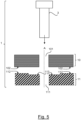
Fig. 3 ] illustrates a sectional exploded view of an assembly for a vehicle according to a first non-limitative embodiment of the invention, said assembly comprising a first structure and a second structure that are joined along a joint interface and a fastener, the first structure comprising an undercut arranged according to a second non-limitative embodiment, - [
Fig. 4 ] illustrates a sectional exploded view of an assembly for a vehicle according to a second non-limitative embodiment of the invention, said assembly comprising a first structure and a second structure that are joined along a joint interface and a fastener, the second structure comprising an undercut arranged according to a first non-limitative embodiment, - [
Fig. 5 ] illustrates a sectional exploded view of an assembly for a vehicle according to a second non-limitative embodiment of the invention, said assembly comprising a first structure and a second structure that are joined along a joint interface and a fastener, the second structure comprising an undercut arranged according to a second non-limitative embodiment, - [
Fig. 6 ] illustrates a sectional exploded view of an assembly for a vehicle according to a third non-limitative embodiment of the invention, said assembly comprising a first structure and a second structure that are joined along a joint interface and a fastener, both first and second structures comprising each an undercut arranged according to a first non-limitative embodiment, - [
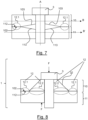
Fig. 7 ] illustrates a sectional view of the assembly offigure 6 when the first structure and the second structure are positioned opposite one to each other so as to be in contact and when no compression force is applied to the first structure or the second structure via the fastener, according to a non-limitative embodiment, - [
Fig. 8 ] illustrates a sectional assembled view of the assembly offigure 6 when a compression force is applied to the first structure or the second structure via the fastener, according to a non-limitative embodiment, - [
Fig. 9 ] illustrates a method of assembling a first structure and a second structure along a joint interface of anyfigures 1 to 6 , according to a first non-limitative embodiment, - [
Fig. 10 ] illustrates a method of assembling a first structure and a second structure along a joint interface of anyfigures 1 to 6 , according to a second non-limitative embodiment. - The present invention relates to an
assembly 1 for a vehicle 2, saidassembly 1 being described in reference tofigures 1 to 8 , according to non-limitative embodiments. In a non-limitative embodiment, said vehicle 2 is an automobile vehicle. - In the following, by "opposite", one means in vis à vis of.
- As illustrated in
figure 1 ,3 to 6 , and8 theassembly 1 comprises : - a
first structure 10, - a
second structure 11, - a
fastener 3. - In a non-limitative embodiment, the
first structure 10 is independent from the body of the vehicle 2 and saidsecond structure 11 is part of the body of the vehicle 2. - In a non-limitative embodiment, the
first structure 10 is a telematic control unit referred as to TCU. In a non-limitative embodiment, thesecond structure 11 is thehood 20 of the vehicle 2. In this case, in a non-limitative example, the TCU is fixed under the hood, near the engine of the vehicle. - The
first structure 10 and thesecond structure 11 are joined along ajoint interface 12 illustrated infigures 7 and 8 . For clarity of the figures, the grooves to delimit thefirst structure 10 and thesecond structure 11 are not illustrated infigures 7 and 8 . - The
first structure 10 presents afirst contact surface 102 and thesecond structure 11 presents asecond contact surface 112. When thefirst structure 10 comprises an undercut 103, thefirst contact surface 102 is arranged around said undercut 103. When thesecond structure 11 comprises an undercut 113, thesecond contact surface 112 is arranged around said undercut 113. When there is noundercut 103, thefirst contact surface 102 extends along the wholefirst structure 10. When there is noundercut 113, thesecond contact surface 112 extends along the wholesecond structure 11. - The
joint interface 12 comprises two parts 12.1 and 12.2. - As illustrated in
figures 7 and 8 , the first part 12.1 of thejoint interface 12 is formed by saidfirst contact surface 102 and saidsecond contact surface 112 when they are into contact and where theundercut 103 is not arranged. - As illustrated in
figure 8 , the second part 12.2 of thejoint interface 12 is formed by a contact area 12.2 that is the contact area where thefirst structure 10 and thesecond structure 11 come into contact where the at least one undercut 103, 113 is arranged. The undercut 103, 113 is described later in the following. - As illustrated in
figure 7 , in a non-limitative embodiment, thefirst structure 10 extends longitudinally along an axis B, and thesecond structure 11 extends longitudinally along an axis B'. In a non-limitative embodiment, the longitudinal axis B' is parallel to the longitudinal axis B. Thefastener 3 extends longitudinally along an axis A. The axis A is perpendicular to the axis Band B'. - The
first structure 10 presents a first thickness e. The second structure presents a second thickness e'. - As illustrated in
figures 1 ,3 to 6 , thefirst structure 10 comprises at least onefirst hole 101 that passes through the wholefirst structure 10, that is to say that it passes through the first thickness e of saidfirst structure 10 along the axis A. Thesecond structure 10 comprises at least onesecond hole 111 that passes through the wholesecond structure 11, that is to say that it passes through the second thickness e' of saidsecond structure 11 along the axis A. - In a non-limitative embodiment not illustrated, the
first structure 10 comprises a plurality offirst holes 101 and thesecond structure 11 comprises a plurality ofsecond holes 111. - In a non-limitative embodiment illustrated in the figures, the
first structure 10 comprises onefirst hole 101 and thesecond structure 11 comprises onesecond hole 111. This non-limitative embodiment is taken as a non-limitative example in the following. - The
second hole 111 is arranged opposite to saidfirst hole 101. As illustrated infigures 7 and 8 , thefastener 3 passes through thefirst hole 101 and thesecond hole 111. - In a non-limitative embodiment, the
fastener 3 is a screw (illustrated infigure 9 ). In this case, thefirst hole 101 and thesecond hole 111 are threaded holes. Infigure 9 , for simplicity, the thread of the holes and of thescrew 3 is not drawn. In another non-limitative embodiment, thefastener 3 is composed of a bolt 3.1 and of a nut 3.2 (illustrated infigure 10 ). In this case, thefirst hole 101 and thesecond hole 111 are also called bolt holes. - The
fastener 3 is configured to assemble thefirst structure 10 and thesecond structure 11 together. To do so, a compression force F illustrated infigure 8 is applied to thefirst structure 10 and to thesecond structure 11 via thefastener 3. - At least one of the
first structure 10 or of thesecond structure 11 comprises at least one undercut referred to as respectively 103, 113. The undercut 103, 113 is arranged respectively around said at least onefirst hole 101 or around said at leastsecond hole 111. In a non-limitative example, the undercut 103, 113 has a circular form in an upper view. In this case, it is circumferentially arranged around said at least onefirst hole 101 or around said at leastsecond hole 111. - When there is no compression force F applied and when the
first structure 10 and thesecond structure 11 are positioned opposite one to each other as illustrated infigure 7 so that they are into contact, thefirst contact surface 102 and thesecond contact surface 112 are in contact altogether and they form the first part 12.1 of thejoint interface 12. - When a compression force F is applied via the
fastener 3 as illustrated infigure 8 , the undercut 103, 113 comes into contact respectively with theopposite structure joint interface 12. Either it comes into contact with acontact surface opposite structure opposite structure - When the vehicle 2 is moving, in the case of the non-limitative embodiment of the TCU and the hood, the
first structure 10 moves horizontally along the axis B relatively to thesecond structure 11 which is the hood. In other words, there is a displacement of the TCU relative to the hood because of the vibrations of the vehicle 2. - The undercut(s) 103, 113 permits to add a larger contact pressure between the
first structure 10 and thesecond structure 11 of theassembly 1 so that the horizontal displacement of thefirst structure 10 relative to thesecond structure 11 is lower than when theassembly 1 is devoid of undercut(s) 103, 113. - It means that the first natural frequency of the
first structure 10, here the TCU, is higher than the one when theassembly 1 is devoid of an undercut(s) 103, 113. Hence, the first natural frequency of the TCU is higher than the frequency of the vibrations of the vehicle 2. It has a much higher amplitude. In a non-limitative example, the amplitude of the first natural frequency will be four times higher than the one of the vibrations. In a non-limitative example, the frequency of the vibrations is 100Hz, and the first natural frequency will be 400Hz. The result is that when there are some vibrations of thesecond structure 11, here the hood, because the vehicle 2 is moving, the frequency of these vibrations won't affect the first natural frequency of the TCU as it will be negligible compared to the first natural frequency of the TCU. - The undercut 103 of the
first structure 10 is also referred to as first undercut 103. The undercut 113 of thesecond structure 11 is also referred to as second undercut 113. - As illustrated in
figure 1 to 3 , in a first non-limitative embodiment, thefirst structure 10 comprises an undercut 103, whereas thesecond structure 11 is devoid of undercut. In this case, the second part 12.2 of thejoint interface 12 is formed by the undercut 103 and thesecond contact surface 112 when a compression force F is applied via thefastener 3. - As illustrated in
figure 4 and5 , in a second non-limitative embodiment, thesecond structure 11 comprises an undercut 113, whereas thefirst structure 10 is devoid of undercut. In this case, the second part 12.2 of thejoint interface 12 is formed by the undercut 113 and thefirst contact surface 102 when a compression force F is applied via thefastener 3. - As illustrated in
figure 6 , in a third non-limitative embodiment, thefirst structure 10 comprises an undercut 103 and thesecond structure 11 comprises an undercut 113. The undercut is arranged opposite to the undercut 113 so that they are arranged around the axis A in the same manner. Hence, bothfirst structure 10 andsecond structure 11 comprise at least one undercut 103, 113. In this case, the second part 12.2 of thejoint interface 12 is formed by the undercut 103 and by the undercut 113 when a compression force F is applied via thefastener 3. - As illustrated in the figures, the undercut 103, 113 starts respectively from the
first hole 101,second hole 111 of respectively thefirst structure 10 andsecond structure 11 where it belongs to. Hence, as illustrated infigures 1 to 3 andfigure 6 , the undercut 103 of thefirst structure 10 arises from thefirst hole 101. As illustrated infigures 4 ,5 and6 , the undercut 113 of thesecond structure 11 arises from thesecond hole 111. - In a first non-limitative embodiment illustrated in
figure 1 ,4 and6 , the undercut 103, 113 includes a slope s, s' that extends from respectively thehole joint interface 12. Hence, in a sectional view, it has a triangular form that arises from thehole figure 1 , the undercut 103 includes a slope s that extends from thefirst hole 101 to thejoint interface 12. As illustrated infigure 4 , the undercut 113 includes a slope s' that extends from thesecond hole 111 to thejoint interface 12. With the slope s, the undercut 103 comes gradually into contact with thesecond contact surface 112 when a compression force F is applied via thefastener 3, or with the other undercut 113 that is opposite to it. It avoids breaking the material of theassembly 1. The same applies for the slope s'. With the slope s', the undercut 113 comes gradually into contact with thefirst contact surface 102 when a compression force F is applied via thefastener 3, or with the other undercut 103 that is opposite to it. - In a non-limitative embodiment, the slope s makes an angle θ with the
second contact surface 112 that is greater than 0° and less than 45°. The angle θ is illustrated infigure 1 . Infigure 1 , the horizontal line that is in dotted line represents thesecond contact surface 112, as it is an exploded view of theassembly 1 where thefirst structure 10 and thesecond structure 11 are illustrated without any contact. In a non-limitative embodiment, the slope s' makes an angle θ' with thefirst contact surface 102 that is greater than 0° and less than 45°. The angle θ' is illustrated infigure 4 . Infigure 4 , the horizontal line that is in dotted line represents thefirst contact surface 102, as it is an exploded view of theassembly 1 where thefirst structure 10 and thesecond structure 11 are illustrated without any contact. - In a second non-limitative embodiment illustrated in
figure 3 and5 , the undercut 103, 113 has a rectangular form in a sectional view. As illustrated infigure 3 , the undercut 103 has a flat surface. In a non-limitative embodiment, the flat surface is parallel to thefirst contact surface 102. As illustrated infigure 5 , the undercut 113 has a flat surface. In a non-limitative embodiment, the flat surface is parallel to thesecond contact surface 112. It is to be noted that the rectangular form is less robust than the triangle form, as it can break, in particular around the corners, if there is too much compression force F applied via thefastener 3. - In a non-limitative embodiment illustrated in
figure 2 , the undercut 103 has an upper view circular form. The same applies for the undercut 113 although it is not illustrated. This form is easy to process and is uniform around thehole 101. The distribution of the compression force F is therefore uniform on the whole undercut 103. The same applies for the undercut 113 with thehole 111. - In a non-limitative embodiment, when the
first structure 10 is a TCU, the undercut 103, 113 has a radius r equal or larger than the radius of thefastener 3. It is to be noted that the range value of the radius r depends on the size of thefastener 3 and of thefirst structure 10 and of thesecond structure 11. The bigger thefastener 3 is, the bigger the radius r of the undercut 103, 113 is. It is to be noted that the size of the diameter of theundercuts first structure 10 and the hood as thesecond structure 11, the radius r is of 8 millimeters. - It is to be noted that when a compression force F is applied, it creates a
pressure cone 32 illustrated infigure 8 . It is to be noted that the value of the compression force F depends on the type offastener 3 that is used. The compression force F is transmitted under a triangle in a sectional view that represents thepressure cone 32. In other words, the force distribution travels in a conical way. Thepressure cone 32 is relative to the size of the undercut 103, 113. In other words, thepressure cone 32 is present till the undercut area. It means that the wider the undercut 103, 113 is, the bigger thepressure cone 32 is. - When a compression force F is applied, the undercut 103, 113 is configured to come into contact, within the
pressure cone 32 of saidfastener 3, with a surface (either thecontact surface structure - As illustrated in
figures 1 and3 , the undercut 103 will come into contact with thesecond contact surface 112. As illustrated infigures 4 and5 , the undercut 113 will come into contact with thefirst contact surface 102. As illustrated infigure 6 , the undercut 103 will come into contact with the undercut 113. - In a non-limitative embodiment illustrated in
figure 8 , the undercut 103, 113 is arranged within thispressure cone 32. It doesn't go beyond thepressure cone 32. In other words, when it has an upper view circular form, the circular form is within thepressure cone 32. In a non-limitative embodiment, the radius r of the undercut 103, 113 is equal to the radius of thepressure cone 32. In another non-limitative embodiment, the radius r of the undercut 103, 113 is smaller than the radius of thepressure cone 32. - The
first structure 10 and thesecond structure 11 are assembled together according tomethod 5. Themethod 5 for assembling thefirst structure 10 and thesecond structure 11 along thejoint interface 12 is described in reference tofigure 9 andfigure 10 .Figure 9 illustrated themethod 5 when a screw is used as afastener 3.Figure 10 illustrated themethod 5 when afastener 3, composed of a bolt 3.1 and a nut 3.2, is used. In the non-limitative embodiment described, thefirst structure 10 comprises onefirst hole 101 and thesecond structure 11 comprises onesecond hole 111. In the non-limitative embodiment described, thefirst structure 10 comprises one undercut 103 that is arranged around thefirst hole 101, and thesecond structure 11 comprises one undercut 113 that is arranged around thesecond hole 111. - In step E1, the
first structure 10 with onefirst hole 101 that passes through the wholefirst structure 10 is provided on a production line. - In step E2, the
second structure 11 with onesecond hole 111 that passes through the wholesecond structure 11 on the production line. - In step E3, the
first structure 10 and thesecond structure 11 are positioned so that thefirst contact surface 102 and thesecond contact surface 112 come into contact and form part of thejoint interface 12 and so that thesecond hole 111 is arranged opposite to thefirst hole 101. - In step E4, the
fastener 3 is positioned through thefirst hole 101 and thesecond hole 111. It passes through them. Infigure 9 , the positioning is performed by screwing thefastener 3 so that the body of thefastener 3 passes through thefirst hole 101 and thesecond hole 111. Infigure 10 , the positioning is performed by screwing the bolt 3.1 so that the body of the bolt 3.1 passes through thefirst hole 101 and thesecond hole 111. - In sept E5, a compression force F is applied on the
first structure 10 and on thesecond structure 11 by means of thefastener 3 so that the undercut 103 comes into contact with a surface of the structure, here thesecond structure 11 that is opposite to the one it belongs to (here, the first structure 10). The surface is either an opposite undercut or a contact surface. The compression force F acts from top and also from bottom of theassembly 1. Infigure 9 , the compression force F results from a torque which is applied when screwing thescrew 3. Thepressure cone 32 starts from the screw'shead 3. Infigure 10 , the compression force F results from a torque which is applied when screwing the nut 3.2 around the body of the bolt 3.1. Thepressure cone 32 starts from the bolt'shead 3. Thanks to the undercut 103, the pressure cone area is extended so that thepressure cone 32 is present till the undercut area. - In the non-limitative embodiment illustrated, the undercut 103 comes into contact with the undercut 113. It comes into contact within the
pressure cone 32. The contact area 12.2 where both undercuts 103 and 113 come into contact completes thejoint interface 12. For clarity of thefigure 9 , due to the grooves, there is no reference 12.2 and 12. One should refer tofigure 8 . Hence, thefirst structure 10 and thesecond structure 11 are assembled altogether. In the non-limitative embodiment of the TCU and the hood, the TCU is hence assembled to the hood and maintained into position under the hood of the vehicle 2. - It is to be understood that the present invention is not limited to the aforementioned applications. It is to be understood that the present invention is not limited to the aforementioned embodiments and variations and modifications may be made without departing from the scope of the invention. In this respect, the following remarks are made. All statements herein reciting principles, aspects, and embodiments of the invention, as well as specific examples thereof, are intended to encompass equivalents thereof. Hence, in other non-limitative embodiments, another application where the
assembly 1 of the invention can be used is the application of housing appliances or machineries. Hence, in other non-limitative embodiments, thefirst structure 10 is an engine control unit, a sensor, a camera, a central control unit of the vehicle 2. Hence, in other non-limitative embodiments, thesecond structure 11 is the roof, the trunk or the tailgate of the vehicle 2. In the non-limitative example of the roof, in this case, thesecond structure 11 is a decorative part of the roof and the TCU is fixed on this decorative part. - Hence, some embodiments of the invention may comprise one or a plurality of the following advantages:
- by removing some material within the
first structure 10 and/or thesecond structure 11, one creates one or a plurality ofundercuts assembly 1. Thus, theassembly 1 won't be affected by the vibrations frequency of the vehicle 2 when it is moving, - it is a better solution than a solution which consists in adding some material, such as some rubber, to create a gap between the
first structure 10 and thesecond structure 11 inside the pressure cone and outside the pressure cone, that is to say on both sides of the rubber, as this solution with the rubber results in that :- there is some looseness in the
assembly 1, - the
assembly 1 is prone to vibrate in different directions vertical and horizontal, - there are some vibrations in the gap when the vehicle is moving,
assembly 1 of the invention doesn't have these problems, - there is some looseness in the
- it is a simple solution and easy to process.
Claims (15)
- Assembly (1) for a vehicle (2) comprising :- a first structure (10) and a second structure (11) that are joined along a joint interface (12), said first structure (10) comprising at least one first hole (101) that passes through the whole first structure (10) and said second structure (11) comprising at least one second hole (111) that passes through the whole second structure (11) and that is arranged opposite to said at least one first hole (101),- a fastener (3) positioned through the said at least one hole (101) and the said at least one second hole (102),wherein at least one of said first structure (10) or said second structure (11) comprises at least one undercut (103, 113) that is arranged respectively around said at least one first hole (101) or around said at least one second hole (111).
- Assembly (1) according to claim 1, wherein both first structure (10) and second structure (11) comprise at least one undercut (103, 113).
- Assembly (1) according to any of the preceding claims, wherein said fastener (3) applies a compression force (F) on said at least one undercut (103, 113) so that it is in contact in a contact area (12.2) with a surface (102, 112, 103, 113) of the first structure (10) or of the second structure (11) opposite to the one said at least one undercut (103, 113) belongs to, said contact area (12.2) forming a part (12.2) of the joint interface (12).
- Assembly (1) according to any of the preceding claims, wherein said at least one undercut (103, 113) starts from said at least one first hole (101) or from said at least one second hole (111) around which it is arranged.
- Assembly (1) according to any of the preceding claims, wherein said first structure (10) presents a first contact surface (102) and said second structure (11) presents a second contact surface (112), said first contact surface (102) and said second contact surface (112) forming a part (12.1) of the joint interface (12).
- Assembly (1) according to any of the preceding claims, wherein said at least one undercut (103, 113) includes a slope (s, s') that extends from said at least one first hole (101) or from said at least one second hole (111) around which it is arranged to the joint interface (12).
- Assembly (1) according to the preceding claim 5, wherein said at least one undercut (103, 113) has a flat surface that is parallel to the first contact surface (102) or to the second contact surface (112) of respectively the first structure (10) or the second structure (11) to which said at least one undercut (103, 113) belongs to.
- Assembly (1) according to any of the preceding claims, wherein said at least one undercut (103, 113) has an upper view circular form.
- Assembly (1) according to any of the preceding claims, wherein said first structure (10) is a Telematic Control Unit.
- Assembly (1) according to any of the preceding claims, wherein said second structure (11) is a hood or a roof.
- A first structure (10) comprising at least one first hole (101) that extends through the whole first structure (10), said at least one first hole (101) being configured to receive a fastener (3), wherein said first structure (10) comprises at least one undercut (103) that is arranged around said at least one first hole (101).
- A second structure (11) comprising at least one second hole (111) that extends through the whole second structure (11), said at least one second hole (111) being configured to receive a fastener (3), wherein said second structure (11) comprises at least one undercut (113) that is arranged around said at least one second hole (111).
- A method (5) of assembling a first structure (10) and a second structure (11) along a joint interface (12), wherein said method (5) comprising:- providing a first structure (10) comprising at least one first hole (101) that passes through the whole first structure (10),- providing a second structure (11) comprising at least one second hole (111) that passes through the whole second structure (11), at least one of said first structure (10) or said second structure (11) comprising at least one undercut (103, 113) that is arranged respectively around said at least one first hole (101) or around said at least one second hole (111),- positioning said first structure (10) and said second structure (11) so that they come into contact altogether and so that said at least one second hole (111) is arranged opposite to said at least one first hole (101),- positioning a fastener (3) through said at least one first hole (101) and through said at least one second hole (111),- applying a compression force (F) on the first structure (10) and on the second structure (11) by means of said fastener (3) so that said at least one undercut (103, 113) comes into contact in a contact area (12.2) with a surface (102, 112, 103, 113) of the first structure (10) or of the second structure (11) opposite to the one said at least one undercut (103, 113) belongs to, said contact area (12.2) forming a part of the joint interface (12).
- A method (5) according to the preceding claim, wherein the surface with which said at least one undercut (103, 113) comes into contact is the first contact surface (102) or the second contact surface (112) or an opposite undercut (113, 103).
- A method (5) according to claim 13 or claim 14, wherein said first structure (10) presents a first contact surface (102) and said second structure (11) presents a second contact surface (112), and wherein said first structure (10) and said second structure (11) are positioned so that said first contact surface (102) and said second contact surface (112) come into contact to form a first part (12.1) of the joint interface (12).
Priority Applications (2)
| Application Number | Priority Date | Filing Date | Title |
|---|---|---|---|
| EP23180411.3A EP4481210B1 (en) | 2023-06-20 | 2023-06-20 | Assembly for a vehicle comprising a first structure and a second structure |
| PCT/EP2024/066085 WO2024260799A1 (en) | 2023-06-20 | 2024-06-11 | Assembly for a vehicle comprising a first structure and a second structure |
Applications Claiming Priority (1)
| Application Number | Priority Date | Filing Date | Title |
|---|---|---|---|
| EP23180411.3A EP4481210B1 (en) | 2023-06-20 | 2023-06-20 | Assembly for a vehicle comprising a first structure and a second structure |
Publications (2)
| Publication Number | Publication Date |
|---|---|
| EP4481210A1 true EP4481210A1 (en) | 2024-12-25 |
| EP4481210B1 EP4481210B1 (en) | 2026-04-22 |
Family
ID=86903941
Family Applications (1)
| Application Number | Title | Priority Date | Filing Date |
|---|---|---|---|
| EP23180411.3A Active EP4481210B1 (en) | 2023-06-20 | 2023-06-20 | Assembly for a vehicle comprising a first structure and a second structure |
Country Status (2)
| Country | Link |
|---|---|
| EP (1) | EP4481210B1 (en) |
| WO (1) | WO2024260799A1 (en) |
Citations (4)
| Publication number | Priority date | Publication date | Assignee | Title |
|---|---|---|---|---|
| WO1986000118A1 (en) * | 1984-06-16 | 1986-01-03 | John Orr | Improvements in fastenings and seals |
| WO2013007368A1 (en) * | 2011-07-13 | 2013-01-17 | Brose Fahrzeugteile Gmbh & Co. Kg, Hallstadt | Assembly comprising at least two components that are fixed together |
| US20140305046A1 (en) * | 2010-01-25 | 2014-10-16 | Vermont Slate & Copper Services, Inc. | Roof mount assembly |
| WO2017044707A1 (en) * | 2015-09-10 | 2017-03-16 | Newpark Mats & Integrated Services Llc | Apparatus and methods for connecting components of a support surface |
Family Cites Families (1)
| Publication number | Priority date | Publication date | Assignee | Title |
|---|---|---|---|---|
| US20180347616A1 (en) * | 2017-06-02 | 2018-12-06 | National Technology & Engineering Solutions Of Sandia, Llc | Linearized joint interface |
-
2023
- 2023-06-20 EP EP23180411.3A patent/EP4481210B1/en active Active
-
2024
- 2024-06-11 WO PCT/EP2024/066085 patent/WO2024260799A1/en not_active Ceased
Patent Citations (4)
| Publication number | Priority date | Publication date | Assignee | Title |
|---|---|---|---|---|
| WO1986000118A1 (en) * | 1984-06-16 | 1986-01-03 | John Orr | Improvements in fastenings and seals |
| US20140305046A1 (en) * | 2010-01-25 | 2014-10-16 | Vermont Slate & Copper Services, Inc. | Roof mount assembly |
| WO2013007368A1 (en) * | 2011-07-13 | 2013-01-17 | Brose Fahrzeugteile Gmbh & Co. Kg, Hallstadt | Assembly comprising at least two components that are fixed together |
| WO2017044707A1 (en) * | 2015-09-10 | 2017-03-16 | Newpark Mats & Integrated Services Llc | Apparatus and methods for connecting components of a support surface |
Also Published As
| Publication number | Publication date |
|---|---|
| EP4481210B1 (en) | 2026-04-22 |
| WO2024260799A1 (en) | 2024-12-26 |
Similar Documents
| Publication | Publication Date | Title |
|---|---|---|
| US9476479B2 (en) | Tubular vibration-damping device used for vibration-damping connecting rod, vibration-damping connecting rod using the same, and method of manufacturing vibration-damping connecting rod | |
| KR101985316B1 (en) | Fastening member | |
| JP2005180574A (en) | Dynamic damper | |
| US20120298832A1 (en) | Vibration-damping device | |
| KR20190135083A (en) | Dynamic damper | |
| US1208620A (en) | Washer. | |
| EP2835541B1 (en) | Anti-rattle sleeve for a hinge joint | |
| EP3287662B1 (en) | Hydraulic engine mount with two channels | |
| US6349470B1 (en) | Retaining method for spherical bearing | |
| EP4481210A1 (en) | Assembly for a vehicle comprising a first structure and a second structure | |
| JP6909571B2 (en) | Anti-vibration device | |
| US9587723B2 (en) | Device for pressing a transmission element | |
| US20060157903A1 (en) | Cylindrical dynamic damper | |
| US10883514B2 (en) | Blower fan | |
| US7297066B2 (en) | Resin joint boot | |
| KR102283900B1 (en) | fastener of door trim | |
| JPH1059206A (en) | Steering joint unit | |
| JP2016173171A (en) | Anti-vibration damper for automobile | |
| JP2018009870A (en) | Knocking sensor | |
| US6343782B1 (en) | Vibration canceller | |
| JP2001200882A (en) | Liquid sealing vibration isolating device | |
| US11946520B2 (en) | Vibration-damping device | |
| JPH08177976A (en) | Dynamic damper | |
| JP2530091Y2 (en) | Pulley structure of continuously variable transmission | |
| KR20050022384A (en) | Insulator for engine mounting |
Legal Events
| Date | Code | Title | Description |
|---|---|---|---|
| PUAI | Public reference made under article 153(3) epc to a published international application that has entered the european phase |
Free format text: ORIGINAL CODE: 0009012 |
|
| STAA | Information on the status of an ep patent application or granted ep patent |
Free format text: STATUS: THE APPLICATION HAS BEEN PUBLISHED |
|
| AK | Designated contracting states |
Kind code of ref document: A1 Designated state(s): AL AT BE BG CH CY CZ DE DK EE ES FI FR GB GR HR HU IE IS IT LI LT LU LV MC ME MK MT NL NO PL PT RO RS SE SI SK SM TR |
|
| STAA | Information on the status of an ep patent application or granted ep patent |
Free format text: STATUS: REQUEST FOR EXAMINATION WAS MADE |
|
| 17P | Request for examination filed |
Effective date: 20250613 |
|
| GRAJ | Information related to disapproval of communication of intention to grant by the applicant or resumption of examination proceedings by the epo deleted |
Free format text: ORIGINAL CODE: EPIDOSDIGR1 |
|
| GRAP | Despatch of communication of intention to grant a patent |
Free format text: ORIGINAL CODE: EPIDOSNIGR1 |
|
| GRAP | Despatch of communication of intention to grant a patent |
Free format text: ORIGINAL CODE: EPIDOSNIGR1 |
|
| STAA | Information on the status of an ep patent application or granted ep patent |
Free format text: STATUS: GRANT OF PATENT IS INTENDED |
|
| INTG | Intention to grant announced |
Effective date: 20260102 |
|
| GRAS | Grant fee paid |
Free format text: ORIGINAL CODE: EPIDOSNIGR3 |
|
| GRAA | (expected) grant |
Free format text: ORIGINAL CODE: 0009210 |
|
| STAA | Information on the status of an ep patent application or granted ep patent |
Free format text: STATUS: THE PATENT HAS BEEN GRANTED |
|
| AK | Designated contracting states |
Kind code of ref document: B1 Designated state(s): AL AT BE BG CH CY CZ DE DK EE ES FI FR GB GR HR HU IE IS IT LI LT LU LV MC ME MK MT NL NO PL PT RO RS SE SI SK SM TR |
|
| REG | Reference to a national code |
Ref country code: CH Ref legal event code: F10 Free format text: ST27 STATUS EVENT CODE: U-0-0-F10-F00 (AS PROVIDED BY THE NATIONAL OFFICE) Effective date: 20260422 Ref country code: GB Ref legal event code: FG4D |