EP4481200A1 - Hydraulic connection arrangement for connecting a hydraulic system with a pump unit, wherein the hydraulic connection arrangement comprises at least a wear part and a valve, and furthermore comprises a connecting part, system, method for removing and/or exchanging a wear part and/or for removing and/or exchanging at least part of a hydraulic connection arrangement, use of a hydraulic connection arrangement - Google Patents
Hydraulic connection arrangement for connecting a hydraulic system with a pump unit, wherein the hydraulic connection arrangement comprises at least a wear part and a valve, and furthermore comprises a connecting part, system, method for removing and/or exchanging a wear part and/or for removing and/or exchanging at least part of a hydraulic connection arrangement, use of a hydraulic connection arrangement Download PDFInfo
- Publication number
- EP4481200A1 EP4481200A1 EP23305967.4A EP23305967A EP4481200A1 EP 4481200 A1 EP4481200 A1 EP 4481200A1 EP 23305967 A EP23305967 A EP 23305967A EP 4481200 A1 EP4481200 A1 EP 4481200A1
- Authority
- EP
- European Patent Office
- Prior art keywords
- connection arrangement
- hydraulic
- hydraulic connection
- connecting part
- valve
- Prior art date
- Legal status (The legal status is an assumption and is not a legal conclusion. Google has not performed a legal analysis and makes no representation as to the accuracy of the status listed.)
- Granted
Links
Images

Classifications
-
- F—MECHANICAL ENGINEERING; LIGHTING; HEATING; WEAPONS; BLASTING
- F04—POSITIVE - DISPLACEMENT MACHINES FOR LIQUIDS; PUMPS FOR LIQUIDS OR ELASTIC FLUIDS
- F04B—POSITIVE-DISPLACEMENT MACHINES FOR LIQUIDS; PUMPS
- F04B53/00—Component parts, details or accessories not provided for in, or of interest apart from, groups F04B1/00 - F04B23/00 or F04B39/00 - F04B47/00
- F04B53/16—Casings; Cylinders; Cylinder liners or heads; Fluid connections
-
- F—MECHANICAL ENGINEERING; LIGHTING; HEATING; WEAPONS; BLASTING
- F04—POSITIVE - DISPLACEMENT MACHINES FOR LIQUIDS; PUMPS FOR LIQUIDS OR ELASTIC FLUIDS
- F04B—POSITIVE-DISPLACEMENT MACHINES FOR LIQUIDS; PUMPS
- F04B53/00—Component parts, details or accessories not provided for in, or of interest apart from, groups F04B1/00 - F04B23/00 or F04B39/00 - F04B47/00
- F04B53/10—Valves; Arrangement of valves
-
- F—MECHANICAL ENGINEERING; LIGHTING; HEATING; WEAPONS; BLASTING
- F04—POSITIVE - DISPLACEMENT MACHINES FOR LIQUIDS; PUMPS FOR LIQUIDS OR ELASTIC FLUIDS
- F04B—POSITIVE-DISPLACEMENT MACHINES FOR LIQUIDS; PUMPS
- F04B53/00—Component parts, details or accessories not provided for in, or of interest apart from, groups F04B1/00 - F04B23/00 or F04B39/00 - F04B47/00
- F04B53/22—Arrangements for enabling ready assembly or disassembly
Definitions
- the present invention relates a hydraulic connection arrangement for connecting a hydraulic system with a pump unit, wherein the hydraulic connection arrangement comprises at least a wear part and a valve, and furthermore comprises a connecting part, wherein the hydraulic connection arrangement comprises a first side and a second side, wherein the hydraulic connection arrangement is configured to be connected, at its first side, to the pump unit, and, at its second side, to the hydraulic system.
- the present invention relates to a corresponding hydraulic system comprising a plurality of pump units besides the hydraulic system, wherein each pump unit is connected, to the hydraulic system, by means of a respective hydraulic connection arrangement.
- the present invention relates to a method for removing and/or exchanging a wear part and/or for removing and/or exchanging at least part of a hydraulic connection arrangement, wherein the hydraulic connection arrangement connects a hydraulic system with a pump unit, wherein the hydraulic connection arrangement comprises at least the wear part and a valve, and furthermore comprises a connecting part, wherein the hydraulic connection arrangement comprises a first side and a second side, wherein the hydraulic connection arrangement is configured to be connected, at its first side, to the pump unit, and, at its second side, to the hydraulic system.
- the present invention relates to the use of a hydraulic connection arrangement for connecting a hydraulic system with a pump unit or use of a wear part for providing a hydraulic connection arrangement, wherein the hydraulic connection arrangement comprises at least a wear part and a valve, and furthermore comprises a connecting part, wherein the hydraulic connection arrangement comprises a first side and a second side, wherein the hydraulic connection arrangement is configured to be connected, at its first side, to the pump unit, and, at its second side, to the hydraulic system.
- Hydraulic connection arrangements for connecting a hydraulic system with a pump unit are generally know.
- several pump units are connected together to form a pump system that provides the required pressure.
- several pump units are combined to so-called booster pump systems in order to increase an existing water pressure and also to provide an adequate water pressure on higher floors.
- the pump units in such pump systems have usually two hydraulic connection ports, whereby the fluid is sucked in at a suction port and discharged at a discharge port at a higher pressure.
- the hydraulic connection ports are, e.g., formed by a threaded pipe or another connection means.
- such a pump unit is typically connected to a hydraulic system (i.e. typically each one of such pump units is separately connected to the hydraulic system, and typically to a manifold thereof).
- a hydraulic connection arrangement is typically provided for connecting the hydraulic system with each one of the pump units.
- such hydraulic connection arrangement comprise at least a wear part and a valve, wherein the wear part is required to be completely removed (in order to be checked) or even replaced either regularly or in case of sufficient wear.
- a wear part is the use of a non-return valve (or check valve):
- Such a non-return valve (or check valve) typically needs to be checked and/or replaced regularly according to certain intervals, e.g. time intervals - such as, e.g., every year - or usage intervals - such as, e.g., each specific number of operating hours or volumes (of a medium) pumped - in order to ensure its good operation.
- An object of the present invention is to provide a technically simple, effective and cost-effective solution for connecting a hydraulic system with a pump unit in a manner such that the drawbacks of the prior art are able to be avoided as much as possible.
- it should be able to check and/or to remove and/or to replace a wear part (being part of the hydraulic connection arrangement) with the hydraulic system being under pressure, i.e. without the necessity to completely remove a part of the hydraulic system, especially completely remove the manifold, and also without the necessity to completely shut off the hydraulic system and/or isolate it from the water network.
- checking and/or removing and/or replacing of the wear part shall be possible without increased tightness problems and/or leakages (i.e. due to misalignment of components).
- a further object of the present invention is to provide a corresponding hydraulic system, a corresponding method for removing and/or exchanging a wear part and/or for removing and/or exchanging at least part of a hydraulic connection arrangement, a corresponding use of a hydraulic connection arrangement for connecting a hydraulic system with a pump unit, and a corresponding use of a wear part for providing a hydraulic connection arrangement.
- a hydraulic connection arrangement for connecting a hydraulic system with a pump unit, wherein the hydraulic connection arrangement comprises at least a wear part and a valve, and furthermore comprises a connecting part, wherein the hydraulic connection arrangement comprises a first side and a second side, wherein the hydraulic connection arrangement is configured to be connected, at its first side, to the pump unit, and, at its second side, to the hydraulic system, wherein the second side of the hydraulic connection arrangement corresponds to one connection side of the valve, wherein the wear part, the connecting part and the valve are connected with each other by means of screw connections to form the hydraulic connection arrangement, and wherein the connecting part comprises a union nut and a lock nut.
- the connecting part having, or comprising, both the union nut and the lock nut, provides - especially by means of an interaction of a thread portion with a corresponding internal thread, e.g. of the valve, or the wear part or the pump unit - the possibility to easily replace and/or remove and/or exchange the wear part.
- the use of threaded connections also advantageously realizes benefits, especially with regard to an increased tightness and the possibility to realize, for a given interior diameter, smaller outer (or external) diameter, especially of a sliding piece.
- the hydraulic connection arrangement advantageously provides the possibility to avoid drawbacks associated with such an exchange and/or a removal of the wear part in relation to hydraulic systems conventionally known.
- drawbacks include, e.g., quality problems related to leakage due to the difficulty to center the wear part, especially in case the wear part corresponds to a non-return valve.
- the concept of the present invention is able to be applied to a wide variety of different hydraulic systems, especially hydraulic systems comprising a plurality of pump units besides the hydraulic system, wherein each pump unit is connected, to the hydraulic system, by means of a respective hydraulic connection arrangement according to the present invention.
- the present invention provides the possibility to not having to shut off (at an inspection or revision point in time) all pump units (and corresponding hydraulic connection arrangements) of such a hydraulic system but only the one (pump unit and hydraulic connection arrangement) under revision or inspection; this especially provides the advantage to be able to continuously operate such a hydraulic system despite the wear part (of, e.g., one of the involved hydraulic connection arrangements) being removed and/or exchanged, i.e. there is the possibility to more easily remove (or replace) a wear part, e.g.
- this advantage is able to be realized and applied for a wide variety of different categories of hydraulic systems and/or pump units involved, e.g. all 6" pump units and/or regarding pump units or hydraulic systems in the range of being able to pump between 2 and 6 cubic meters per hour and/or to pump between 10 and 16 cubic meters per hour.
- non-return valve or non-return valve cartridge
- non-return valve housing which is not possible in conventionally known hydraulic systems as the non-return valve (or the non-return valve cartridge) has to be broken in order to remove it from the non-return valve housing.
- a further advantage according to the present invention concerns the possibility to use standard ball valves: Regarding the whole range of different power specifications, it is advantageously possible to use standard ball valves, e.g. brass ball valves (or stainless steel ball valves), hence there is no need, according to the present invention, to use (typically more costly) special ball valves, especially ball valves made of stainless steel.
- standard ball valves e.g. brass ball valves (or stainless steel ball valves)
- Still a further advantage is related to the connecting part comprising the union nut used to tightly connect the connecting part (with, e.g., the wear part) wherein a seal ring is used at the interface of the union nut (e.g., towards a first thread of the wear part).
- this seal ring corresponds to an integrated seal ring (or O-ring) and - especially compared to conventionally known hydraulic systems - it is not possible anymore to loose this O-ring..
- the union nut is used at the connection of the connecting part to the wear part, and wherein the lock nut is used at the connection of the connecting part to the valve, especially to assure this connection and its tightness, wherein the first side of the hydraulic connection arrangement corresponds to one connection side of the wear part, wherein especially the hydraulic connection arrangement is formed
- the union nut is used at the connection of the connecting part to the valve, and wherein the lock nut is used at the connection of the connecting part to the wear part, especially to assure this connection and its tightness, wherein the first side of the hydraulic connection arrangement corresponds to one connection side of the wear part, wherein especially the hydraulic connection arrangement is formed
- the wear part is connected, at the first side of the hydraulic connection arrangement towards the pump unit, by means of a flange connection, especially comprising two screws.
- the first side of the hydraulic connection arrangement corresponds to one connection side of the connecting part, wherein the lock nut and especially a thread portion is used, at this connection side of the connecting part, for its connection to the pump unit, especially to assure this connection and its tightness, the thread portion especially being screwed into an internal thread of the pump unit, wherein especially the hydraulic connection arrangement is formed
- the first side of the hydraulic connection arrangement corresponds to one connection side of the connecting part, wherein the union nut is used, at this connection side of the connecting part, for its connection to the pump unit, wherein especially the hydraulic connection arrangement is formed
- the wear part corresponds to a check valve or to a filter element and/or that the valve corresponds to a ball valve.
- the present invention relates to a hydraulic system comprising a plurality of pump units besides the hydraulic system, wherein each pump unit is connected, to the hydraulic system, by means of a respective hydraulic connection arrangement according to the present invention.
- the present invention relates to a method for removing and/or exchanging a wear part and/or for removing and/or exchanging at least part of a hydraulic connection arrangement, wherein the hydraulic connection arrangement connects a hydraulic system with a pump unit, wherein the hydraulic connection arrangement comprises at least the wear part and a valve, and furthermore comprises a connecting part,
- the present invention relates to the use of a hydraulic connection arrangement for connecting a hydraulic system with a pump unit or to the use of a wear part for providing a hydraulic connection arrangement, especially according to the present invention or for providing an inventive system or for being used in an inventive method, wherein the hydraulic connection arrangement comprises at least a (or the) wear part and a valve, and furthermore comprises a connecting part,
- FIG 1 an exemplary embodiment of a hydraulic connection arrangement 100 is schematically shown according to a perspective view.
- the hydraulic connection arrangement 100 is connected to a pump unit 300 and to a hydraulic system 200.
- the hydraulic connection arrangement 100 comprises a first side A and a second side B. At its first side A, the hydraulic connection arrangement 100 is configured to be connected to the pump unit 300. At its second side B, the hydraulic connection arrangement 100 in configured to be connected to the hydraulic system 200.
- Figure 1 only shows a small portion (such as a pipe end leading to a manifold) of the hydraulic system 200.
- the hydraulic connection arrangement 100 comprises at least a wear part 110 and a valve 130, and furthermore comprises a connecting part 120, wherein the wear part 110, the connecting part 120 and the valve 130 are connected with each other by means of screw connections to form the hydraulic connection arrangement 100.
- the second side B of the hydraulic connection arrangement 100 corresponds to one connection side of the valve 130, and the connecting part 120 comprises a union nut 125 and a lock nut 126.
- the hydraulic connection arrangement 100 comprises the wear part 110, the connecting part 120 and the valve 130 such that the wear part 110 (at one of its two connection sides) is connected to (one of the two connection sides of) the connecting part 120 (using a screw connection), and the connecting part 120 is in turn connected (at its other connection side and again using a screw connection) with (one of the two connection sides of) the valve 130 - i.e. starting from the first side A of the hydraulic connection arrangement 100, the wear part 110 comes first and then comes the connecting part 120; and thereafter the valve 130.
- the parts of the hydraulic connection arrangement 100 - i.e. the wear part 110, the valve 130, and the connecting part 120 - are represented separately and, thus, are more clearly visible:
- the wear part 110 comprises a flange element 112 that is used to tightly connect the first side A of the hydraulic connection arrangement 100, with the pump unit 300, in the exemplary embodiment shown, with a flange of the pump unit 300.
- the connecting part 120 comprises the union nut 125: According to the exemplarily represented embodiment, the union nut 125 is used to tightly connect the connecting part 120 with the wear part 110; according to the exemplary embodiment shown, this is done using a seal ring 125' between the union nut 125 and a first thread 115 of the wear part 110.
- the connecting part 120 comprises the lock nut 126:
- the lock nut 126 is used to tightly connect the connecting part 120 with the valve 130; according to the exemplary embodiment shown, this is done using a further seal ring 126' between the lock nut 126 and the valve 130: an external thread, hereinafter called thread portion 120', of the connecting part 120 (shown, in Figure 2 , on the left hand side of the connecting part 120) is first screwed into an internal thread 136 of the valve 130; this connection is then secured (and tightened) by means of the further seal ring 126' and the lock nut 126 against the valve 130.
- the valve 130 is connected to the hydraulic system 200 using connection techniques known in the art.
- Figures 1 and 2 show an embodiment of the hydraulic connection arrangement 100 where the union nut 125 is used at the connection of the connecting part 120 to the wear part 110, and wherein the lock nut 126 is used at the connection of the connecting part 120 to the valve 130, especially to assure this connection and its tightness.
- the first side A of the hydraulic connection arrangement 100 corresponds to one connection side of the wear part 110.
- the hydraulic connection arrangement 100 is formed by means of another connection side (first thread 115) of the wear part 110 being connected, using the union nut 125, with one connection side of the connecting part 120, and by means of the connecting part 120 being connected, on its other connection side (using the thread portion 120'), with the valve 130, using the lock nut 126.
- the hydraulic connection arrangement 100 it is advantageously possible, according to the present invention, to remove and/or to exchange the wear part 110 and/or to remove and/or exchange at least part of the hydraulic connection arrangement 100, and this despite the fact that the hydraulic connection arrangement 100 is fixedly integrated between the pump unit 300 (on its first side A) and the hydraulic system 200 (on its second side B), i.e.
- the axial distance between the pump unit 300 and the hydraulic system 200 (or between the pump unit 300 and the internal thread 136 of the valve 130) is fixed and cannot be modified, at least not meaningfully enlarged (in order to be able to more easily remove and/or exchange at least a part of a hydraulic connection arrangement 100); to the contrary, it might very well be the case that - in a scenario where the hydraulic system is under pressure - this axial distance (between the pump unit 300 and the hydraulic system 200 or between the pump unit 300 and the internal thread 136 of the valve 130) might be even reduced (e.g. due to mechanical stress and corresponding elastic displacements).
- this is possible by means of using both the union nut 125 and the lock nut 126 of the connecting part 120: in a first step - after the connection of the hydraulic connection arrangement 100, at its first side A, is loosened or opened - the lock nut 126 is loosened with regard to the thread portion 120' of the connecting part (120); in other words, the lock nut 126 is moved, on the thread portion 120', away from the valve 130, thereby providing the possibility to screw (or to rotate) - in a second step - the thread portion 120' further into the internal thread 136 of the valve 130.
- Such screwing (or rotating) of the thread portion 120' further into the internal thread 136 of the valve 130 provides axial space in order to be able to remove and/or to exchange at least a part of the hydraulic connection arrangement 100; the rotation of the thread portion 120' of the connecting part 120 is preferably (but not necessarily) done together with the wear part 110.
- the union nut 125 is loosened or opened, and the wear part 110 is able to be removed and/or exchanged.
- the rotation of the thread portion 120' of the connecting part 120 is not necessarily done together with the wear part 110.
- the wear part 110 is connected, at the first side A of the hydraulic connection arrangement 100 towards the pump unit 300, by means of a flange connection, especially comprising two screws.
- a flange connection especially comprising two screws.
- the flange element 112 being realized as part of the wear part 110 (or connected to the wear part 110) and providing a flange interface or flange connection towards the pump unit 300.
- the connecting part 120 is somehow rotated (about a vertical axis) by 180 degrees such that the locations of the union nut 125 and the lock nut 126 are exchanged, i.e. the union nut 125 is used at the connection of the connecting part 120 to the valve 130, and the lock nut 126 is used at the connection of the connecting part 120 to the wear part 110, especially to assure this connection and its tightness.
- the first side A of the hydraulic connection arrangement 100 corresponds to one connection side of the wear part 110, and especially the hydraulic connection arrangement 100 is formed by means of another connection side (which needs to be an internal thread) of the wear part 110 being connected, using the lock nut 126, with one connection side of the connecting part 120 - namely with the thread portion 120' -, and by means of the connecting part 120 being connected, on its other connection side, with the valve 130, using the union nut 125 (in this case, the valve needs to have an external thread instead of the internal thread 136 as shown in Figure 2 ).
- the first side A of the hydraulic connection arrangement 100 corresponds to one connection side of the connecting part 120 (namely the side of the connecting part 120 having the thread portion 120'), wherein the lock nut 126 is used, at this connection side of the connecting part 120, for its connection to the pump unit 300 (in this case, the pump unit 300 needs to provide an internal thread), especially to assure this connection and its tightness.
- the hydraulic connection arrangement 100 is formed by means of using, at the other connection side of the connecting part 120, the union nut 125, with one connection side of the wear part 110 (i.e. the side corresponding to the first thread 115), and by means of the wear part 110, being connected, on its other connection side, with the valve 130, especially using a further union nut.
- the first side A of the hydraulic connection arrangement 100 corresponds to one connection side of the connecting part 120, wherein the union nut 125 is used, at this connection side of the connecting part 120, for its connection to the pump unit 300 (in this case, the pump unit 300 needs to provide an external thread in order to be able to accommodate the union nut 125).
- especially the hydraulic connection arrangement 100 is formed by means of using, at the other connection side of the connecting part (120), the lock nut 126, with one connection side of the wear part 110 (which needs to be an internal thread), especially to assure this connection and its tightness, and by means of the wear part 110, being connected, on its other connection side, with the valve 130, especially using a further union nut.
- the connecting part 120 is arranged such that an axial distance or an axial space is able to be realized, which axial distance or axial space is used to be able to remove and/or to exchange and/or to mount the wear part 110:
- This axial distance or axial space is able to be realized by means of using the side of the connecting part 120 having the thread portion 120'; after the lock nut 126 (interacting with this thread portion 120') having been loosened, it is possible to rotate (i.e. screw) the connecting part 120 with its thread portion 120' further into an internal thread, thereby providing the axial distance or space.
- the connecting part 120 comprises, on its opposing side (i.e. opposite the thread portion 120'), the union nut 125.
- Figure 2 shows the embodiment where, starting from the first side A of the hydraulic connection arrangement 100 (i.e. at the interface of the pump unit 300), first comes the wear part 110 which is facing the connecting part 120 by means of the connection side of the connecting part 120 having the union nut 125; after the connecting part 120 comes the valve 130, wherein these two are connected using the connection side of the connecting part 120 having the thread portion 120' and the lock nut 126 and using the internal thread 136 of the valve 130 as the internal thread providing the possibility to achieve or realize the axial distance or axial space.
- an internal thread analogous to internal thread 136 of the valve 130 (and having the same functionality) is able to be implemented as part of the wear part 110:
- Such a configuration is possible, according to the present invention, by means of two different embodiments or configurations of the hydraulic connection arrangement 100.
- the connecting part 120 has its two sides inverted (compared to the representation of Figure 2 , i.e.
- the connecting part 120 is rotated by 180 degrees about a vertical axis, or, stated differently, the locations of the union nut 125 and the lock nut 126 are exchanged, and the union nut 125 is used at the connection of the connecting part 120 to the valve 130, whereas the lock nut 126 is used at the connection of the connecting part 120 to the wear part 110 with the wear part 110 needs to have, in this case, the internal thread), according to the other of these embodiments or configurations, the positions of the wear part 110 and the connecting part 120 are exchanged, i.e. starting from the first side A of the hydraulic connection arrangement 100 (i.e.
- the connecting part 120 comes first (facing, the pump unit 300 by means of its connection side having the union nut 125) and the wear part 110 comes second, and both the connecting part 120 and the wear part 110 are connected using the connection side of the connecting part 120 having the lock nut 126 (and the wear part 110 has a corresponding internal thread analogous to internal thread 136 of the valve 130).
- an internal thread is implemented at the interface between the connecting part 120 and the pump unit 300:
- Such an embodiment or configuration corresponds - compared to the representation of Figure 2 - to a rotation (by 180 degrees and about a vertical axis) of not only the connecting part 120 alone but to a rotation of both the connecting part 120 and the wear part 110 (of course, in case of the wear part 110 having a directionality, e.g.
- the wear part 110 needs to be configured such that the required directionality is preserved), i.e. starting from the first side A of the hydraulic connection arrangement 100 (i.e. at the interface of the pump unit 300), again the connecting part 120 comes first (using the connection side of the connecting part 120 having the lock nut 126 and the pump unit 300 having a corresponding internal thread analogous to internal thread 136 of the valve 130 shown in Figure 2 ) and the wear part 110 comes second, and both the connecting part 120 and the wear part 110 are connected by means of the connection side of the connecting part 120 having the union nut 125.
- an axial distance or space is advantageously able to be realized due to the connecting part 120 having the (external) thread portion 120' (and the lock nut 126) and by means of an interaction of that thread portion 120' with a corresponding internal thread - of either the valve 130 (shown in Figures 1 and 2 ), or the wear part 110 or the pump unit 300 - by means of screwing, or rotating, at least the connecting part 120 further into the corresponding internal thread after the lock nut 126 having been loosened.
- the inventive method for removing and/or exchanging the wear part 110 and/or for removing and/or exchanging at least part of the hydraulic connection arrangement 100 is able to be applied: the connecting part 120 comprises the union nut 125 as well as the lock nut 126 and the method comprises loosening or opening the connection of the hydraulic connection arrangement 100 at a location opposite of the lock nut 126, e.g.
- the thread portion 120' of the connecting part 120 is rotated further into the internal thread (of the valve 130 (reference sign 136), or of the wear part or of the pump unit 300) - especially together with the wear part 110 - and the union nut 125 is loosened or opened, and the wear part 110 removed and/or exchanged.
Landscapes
- Engineering & Computer Science (AREA)
- Mechanical Engineering (AREA)
- General Engineering & Computer Science (AREA)
- Details Of Reciprocating Pumps (AREA)
Abstract
wherein the hydraulic connection arrangement comprises a first side and a second side, wherein the hydraulic connection arrangement is configured to be connected, at its first side, to the pump unit, and, at its second side, to the hydraulic system,
wherein the second side of the hydraulic connection arrangement corresponds to one connection side of the valve,
characterized in that the wear part, the connecting part and the valve are connected with each other by means of screw connections to form the hydraulic connection arrangement, wherein the connecting part comprises at least one union nut, wherein the union nut is used to connect the connecting part to the wear part.
Description
- The present invention relates a hydraulic connection arrangement for connecting a hydraulic system with a pump unit, wherein the hydraulic connection arrangement comprises at least a wear part and a valve, and furthermore comprises a connecting part, wherein the hydraulic connection arrangement comprises a first side and a second side, wherein the hydraulic connection arrangement is configured to be connected, at its first side, to the pump unit, and, at its second side, to the hydraulic system.
- Furthermore, the present invention relates to a corresponding hydraulic system comprising a plurality of pump units besides the hydraulic system, wherein each pump unit is connected, to the hydraulic system, by means of a respective hydraulic connection arrangement.
- Additionally, the present invention relates to a method for removing and/or exchanging a wear part and/or for removing and/or exchanging at least part of a hydraulic connection arrangement, wherein the hydraulic connection arrangement connects a hydraulic system with a pump unit, wherein the hydraulic connection arrangement comprises at least the wear part and a valve, and furthermore comprises a connecting part, wherein the hydraulic connection arrangement comprises a first side and a second side, wherein the hydraulic connection arrangement is configured to be connected, at its first side, to the pump unit, and, at its second side, to the hydraulic system.
- Furthermore, the present invention relates to the use of a hydraulic connection arrangement for connecting a hydraulic system with a pump unit or use of a wear part for providing a hydraulic connection arrangement, wherein the hydraulic connection arrangement comprises at least a wear part and a valve, and furthermore comprises a connecting part, wherein the hydraulic connection arrangement comprises a first side and a second side, wherein the hydraulic connection arrangement is configured to be connected, at its first side, to the pump unit, and, at its second side, to the hydraulic system.
- Hydraulic connection arrangements for connecting a hydraulic system with a pump unit are generally know. Typically, several pump units are connected together to form a pump system that provides the required pressure. In particular for water supply, several pump units are combined to so-called booster pump systems in order to increase an existing water pressure and also to provide an adequate water pressure on higher floors.
- The pump units in such pump systems have usually two hydraulic connection ports, whereby the fluid is sucked in at a suction port and discharged at a discharge port at a higher pressure. The hydraulic connection ports are, e.g., formed by a threaded pipe or another connection means.
- Regarding both the suction ports as well as the discharge ports, such a pump unit is typically connected to a hydraulic system (i.e. typically each one of such pump units is separately connected to the hydraulic system, and typically to a manifold thereof). In between each one of the pump units and the hydraulic system (i.e. typically between the manifold (of the hydraulic system) and each one of the pump units), a hydraulic connection arrangement is typically provided for connecting the hydraulic system with each one of the pump units.
- Often, such hydraulic connection arrangement comprise at least a wear part and a valve, wherein the wear part is required to be completely removed (in order to be checked) or even replaced either regularly or in case of sufficient wear. One example of such a wear part is the use of a non-return valve (or check valve): Such a non-return valve (or check valve) typically needs to be checked and/or replaced regularly according to certain intervals, e.g. time intervals - such as, e.g., every year - or usage intervals - such as, e.g., each specific number of operating hours or volumes (of a medium) pumped - in order to ensure its good operation.
In conventionally known hydraulic systems, in order to check or to remove or to replace the wear part, it is often required to completely remove a part of the hydraulic system, especially completely remove the manifold, from the (residual) hydraulic system which requires the hydraulic system to be completely shut off and/or isolated from the water network. - An object of the present invention is to provide a technically simple, effective and cost-effective solution for connecting a hydraulic system with a pump unit in a manner such that the drawbacks of the prior art are able to be avoided as much as possible. Especially, it should be able to check and/or to remove and/or to replace a wear part (being part of the hydraulic connection arrangement) with the hydraulic system being under pressure, i.e. without the necessity to completely remove a part of the hydraulic system, especially completely remove the manifold, and also without the necessity to completely shut off the hydraulic system and/or isolate it from the water network. Furthermore, such checking and/or removing and/or replacing of the wear part shall be possible without increased tightness problems and/or leakages (i.e. due to misalignment of components). A further object of the present invention is to provide a corresponding hydraulic system, a corresponding method for removing and/or exchanging a wear part and/or for removing and/or exchanging at least part of a hydraulic connection arrangement, a corresponding use of a hydraulic connection arrangement for connecting a hydraulic system with a pump unit, and a corresponding use of a wear part for providing a hydraulic connection arrangement.
- The object of the present invention is achieved by a hydraulic connection arrangement for connecting a hydraulic system with a pump unit, wherein the hydraulic connection arrangement comprises at least a wear part and a valve, and furthermore comprises a connecting part, wherein the hydraulic connection arrangement comprises a first side and a second side, wherein the hydraulic connection arrangement is configured to be connected, at its first side, to the pump unit, and, at its second side, to the hydraulic system, wherein the second side of the hydraulic connection arrangement corresponds to one connection side of the valve, wherein the wear part, the connecting part and the valve are connected with each other by means of screw connections to form the hydraulic connection arrangement, and wherein the connecting part comprises a union nut and a lock nut.
- It is thereby advantageously possible according to the present invention to provide the possibility to create an axial distance or space for facilitating the removal and/or the exchange of the wear part and/or for facilitating the removal and/or exchange of at least part of a hydraulic connection arrangement.
According to the present invention, the connecting part, having, or comprising, both the union nut and the lock nut, provides - especially by means of an interaction of a thread portion with a corresponding internal thread, e.g. of the valve, or the wear part or the pump unit - the possibility to easily replace and/or remove and/or exchange the wear part. - Compared to other solutions conventionally known, the use of threaded connections also advantageously realizes benefits, especially with regard to an increased tightness and the possibility to realize, for a given interior diameter, smaller outer (or external) diameter, especially of a sliding piece.
- Once the axial distance or space is realized, by means of loosening the union nut, it is advantageously possible to comparatively easily and quickly remove and/or exchange the wear part and/or remove and/or exchange at least part of the hydraulic connection arrangement - and especially without having to shut off all of the hydraulic system: only the corresponding valve (being part of or related to the hydraulic connection arrangement considered or concerned) needs to be closed in order to hydraulically separate the wear part and/or the hydraulic connection arrangement towards the respective and considered pump unit.
- Hence, according to the present invention, the hydraulic connection arrangement advantageously provides the possibility to avoid drawbacks associated with such an exchange and/or a removal of the wear part in relation to hydraulic systems conventionally known. Such drawbacks include, e.g., quality problems related to leakage due to the difficulty to center the wear part, especially in case the wear part corresponds to a non-return valve.
- Especially, the concept of the present invention is able to be applied to a wide variety of different hydraulic systems, especially hydraulic systems comprising a plurality of pump units besides the hydraulic system, wherein each pump unit is connected, to the hydraulic system, by means of a respective hydraulic connection arrangement according to the present invention. In such a setup or regarding such hydraulic systems, it is especially advantageous to be able to separately interrupt the respective connection between the hydraulic system and the respective pump unit in order to exchange a wear part and/or a part of the hydraulic connection arrangement: Especially, the present invention provides the possibility to not having to shut off (at an inspection or revision point in time) all pump units (and corresponding hydraulic connection arrangements) of such a hydraulic system but only the one (pump unit and hydraulic connection arrangement) under revision or inspection; this especially provides the advantage to be able to continuously operate such a hydraulic system despite the wear part (of, e.g., one of the involved hydraulic connection arrangements) being removed and/or exchanged, i.e. there is the possibility to more easily remove (or replace) a wear part, e.g. a non-return valve or non-return valve cartridge, with the booster or (other) pump units still working. Especially according to the present invention, this advantage is able to be realized and applied for a wide variety of different categories of hydraulic systems and/or pump units involved, e.g. all 6" pump units and/or regarding pump units or hydraulic systems in the range of being able to pump between 2 and 6 cubic meters per hour and/or to pump between 10 and 16 cubic meters per hour.
Especially, it is advantageously possible according to the present invention to remove the non-return valve (or non-return valve cartridge) from non-return valve housing (which is not possible in conventionally known hydraulic systems as the non-return valve (or the non-return valve cartridge) has to be broken in order to remove it from the non-return valve housing. - A further advantage according to the present invention, concerns the possibility to use standard ball valves: Regarding the whole range of different power specifications, it is advantageously possible to use standard ball valves, e.g. brass ball valves (or stainless steel ball valves), hence there is no need, according to the present invention, to use (typically more costly) special ball valves, especially ball valves made of stainless steel.
- Still a further advantage is related to the connecting part comprising the union nut used to tightly connect the connecting part (with, e.g., the wear part) wherein a seal ring is used at the interface of the union nut (e.g., towards a first thread of the wear part). Especially and advantageously, this seal ring corresponds to an integrated seal ring (or O-ring) and - especially compared to conventionally known hydraulic systems - it is not possible anymore to loose this O-ring..
- According to the present invention, it is advantageously possible and preferred that the union nut is used at the connection of the connecting part to the wear part, and wherein the lock nut is used at the connection of the connecting part to the valve, especially to assure this connection and its tightness, wherein the first side of the hydraulic connection arrangement corresponds to one connection side of the wear part, wherein especially the hydraulic connection arrangement is formed
- -- by means of another connection side of the wear part being connected, using the union nut, with one connection side of the connecting part, and
- -- by means of the connecting part being connected, on its other connection side, with the valve, using the lock nut and especially using a thread portion, the thread portion especially being screwed into an internal thread of the valve.
- It is thereby advantageously possible to realize and implement the inventive method in a comparatively simple and efficient manner.
- According to the present invention, it is advantageously furthermore possible and preferred that the union nut is used at the connection of the connecting part to the valve, and wherein the lock nut is used at the connection of the connecting part to the wear part, especially to assure this connection and its tightness, wherein the first side of the hydraulic connection arrangement corresponds to one connection side of the wear part, wherein especially the hydraulic connection arrangement is formed
- -- by means of another connection side of the wear part being connected, using the lock nut and especially a thread portion, with one connection side of the connecting part, the thread portion especially being screwed into an internal thread of the wear part, and
- -- by means of the connecting part being connected, on its other connection side, with the valve, using the union nut.
- It is thereby advantageously possible to realize and implement the inventive method in a comparatively simple and efficient manner; especially, it is advantageously possible to realize the internal thread as part of the wear part such that only the wear part and the connecting part need to be specifically configured in order to implement the present invention.
- According to the present invention, it is furthermore advantageously possible and preferred that the wear part is connected, at the first side of the hydraulic connection arrangement towards the pump unit, by means of a flange connection, especially comprising two screws.
- It is thereby advantageously possible to realize and implement the inventive method in a comparatively simple and efficient manner. Especially, it is advantageously possible that, by means of a flange element as part of the wear part (or connected to the wear part) a flange interface or a flange connection towards the pump unit is able to be realized efficiently.
- According to the present invention, it is furthermore advantageously possible and preferred that the first side of the hydraulic connection arrangement corresponds to one connection side of the connecting part, wherein the lock nut and especially a thread portion is used, at this connection side of the connecting part, for its connection to the pump unit, especially to assure this connection and its tightness, the thread portion especially being screwed into an internal thread of the pump unit, wherein especially the hydraulic connection arrangement is formed
- -- by means of using, at the other connection side of the connecting part, the union nut, with one connection side of the wear part, and
- -- by means of the wear part, being connected, on its other connection side, with the valve, especially using a further union nut.
- It is thereby advantageously possible to realize and implement the inventive method in a comparatively simple and efficient manner; especially, it is advantageously possible to realize the internal thread as part of the pump unit such that only the pump unit and the connecting part need to be specifically configured in order to implement the present invention.
- Furthermore, it is advantageously possible and preferred according to the present invention that the first side of the hydraulic connection arrangement corresponds to one connection side of the connecting part, wherein the union nut is used, at this connection side of the connecting part, for its connection to the pump unit, wherein especially the hydraulic connection arrangement is formed
- -- by means of using, at the other connection side of the connecting part, the lock nut and especially a thread portion, with one connection side of the wear part, especially to assure this connection and its tightness and the thread portion especially being screwed into an internal thread of the wear part, and
- -- by means of the wear part, being connected, on its other connection side, with the valve, especially using a further union nut.
- It is thereby advantageously possible to realize and implement the inventive method in a comparatively simple and efficient manner; especially, it is advantageously possible to realize the internal thread as part of the wear part such that only the wear part and the connecting part need to be specifically configured in order to implement the present invention.
- Furthermore, it is advantageously possible and preferred according to the present invention that the wear part corresponds to a check valve or to a filter element and/or that the valve corresponds to a ball valve.
- It is thereby advantageously possible to realize and implement the inventive method in a comparatively simple and efficient manner.
- Furthermore, the present invention relates to a hydraulic system comprising a plurality of pump units besides the hydraulic system, wherein each pump unit is connected, to the hydraulic system, by means of a respective hydraulic connection arrangement according to the present invention.
- Furthermore, the present invention relates to a method for removing and/or exchanging a wear part and/or for removing and/or exchanging at least part of a hydraulic connection arrangement, wherein the hydraulic connection arrangement connects a hydraulic system with a pump unit, wherein the hydraulic connection arrangement comprises at least the wear part and a valve, and furthermore comprises a connecting part,
- wherein the hydraulic connection arrangement comprises a first side and a second side,
- wherein the hydraulic connection arrangement is configured to be connected, at its first side, to the pump unit, and, at its second side, to the hydraulic system,
- wherein the second side of the hydraulic connection arrangement corresponds to one connection side of the valve,
- characterized in that the wear part, the connecting part and the valve are connected with each other by means of screw connections to form the hydraulic connection arrangement, wherein the connecting part comprises a union nut and a lock nut, wherein the method comprises the following steps:
- -- in a first step, the connection of the hydraulic connection arrangement at its first side is loosened or opened and the lock nut is loosened with regard to a thread portion of the connecting part,
- -- in a second step, the thread portion of the connecting part is rotated, together with the wear part.
- -- in a third step, the union nut is loosened or opened, and the wear part removed and/or exchanged.
- Additionally, the present invention relates to the use of a hydraulic connection arrangement for connecting a hydraulic system with a pump unit or to the use of a wear part for providing a hydraulic connection arrangement, especially according to the present invention or for providing an inventive system or for being used in an inventive method, wherein the hydraulic connection arrangement comprises at least a (or the) wear part and a valve, and furthermore comprises a connecting part,
- wherein the hydraulic connection arrangement comprises a first side and a second side, wherein the hydraulic connection arrangement is configured to be connected, at its first side, to the pump unit, and, at its second side, to the hydraulic system,
- wherein the second side of the hydraulic connection arrangement corresponds to one connection side of the valve,
- characterized in that the connecting part comprises at least one union nut and a lock nut, wherein - in an operative state of the hydraulic connection arrangement - the connecting part is connected to the wear part,
- wherein - in a maintenance state of the hydraulic connection arrangement - the union nut as well as the lock nut is loosened such that the wear part is able to be removed or exchanged while being separated from the hydraulic system by means of the valve being closed.
- These and other characteristics, features and advantages of the present invention will become apparent from the following detailed description, taken in conjunction with the accompanying drawings, which illustrate, by way of example, the principles of the invention. The description is given for the sake of example only, without limiting the scope of the invention. The reference figures quoted below refer to the attached drawings.
-
-
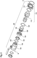
Figure 1 schematically illustrates an exemplary embodiment of the present invention, according to a perspective view: A hydraulic connection arrangement is shown together with a pump unit, the hydraulic connection arrangement being connected to a hydraulic system. -
Figure 2 schematically illustrates an exploded view of the hydraulic connection arrangement according to the present invention. - The present invention will be described with respect to particular embodiments and with reference to certain drawings, but the invention is not limited thereto but only by the claims. The drawings described are only schematic and are non-limiting. In the drawings, the size of some of the elements may be exaggerated and not drawn on scale for illustrative purposes.
- Where an indefinite or definite article is used when referring to a singular noun, e.g. "a", "an", "the", this includes a plural of that noun unless something else is specifically stated.
- Furthermore, the terms first, second, third and the like in the description and in the claims are used for distinguishing between similar elements and not necessarily for describing a sequential or chronological order. It is to be understood that the terms so used are interchangeable under appropriate circumstances and that the embodiments of the invention described herein are capable of operation in other sequences than described or illustrated herein.
- In
Figure 1 , an exemplary embodiment of ahydraulic connection arrangement 100 is schematically shown according to a perspective view. Thehydraulic connection arrangement 100 is connected to apump unit 300 and to ahydraulic system 200.
Thehydraulic connection arrangement 100 comprises a first side A and a second side B. At its first side A, thehydraulic connection arrangement 100 is configured to be connected to thepump unit 300. At its second side B, thehydraulic connection arrangement 100 in configured to be connected to thehydraulic system 200.Figure 1 only shows a small portion (such as a pipe end leading to a manifold) of thehydraulic system 200. - According to the present invention, the
hydraulic connection arrangement 100 comprises at least awear part 110 and avalve 130, and furthermore comprises a connectingpart 120, wherein thewear part 110, the connectingpart 120 and thevalve 130 are connected with each other by means of screw connections to form thehydraulic connection arrangement 100. The second side B of thehydraulic connection arrangement 100 corresponds to one connection side of thevalve 130, and the connectingpart 120 comprises aunion nut 125 and alock nut 126.
Thus, thehydraulic connection arrangement 100 comprises thewear part 110, the connectingpart 120 and thevalve 130 such that the wear part 110 (at one of its two connection sides) is connected to (one of the two connection sides of) the connecting part 120 (using a screw connection), and the connectingpart 120 is in turn connected (at its other connection side and again using a screw connection) with (one of the two connection sides of) the valve 130 - i.e. starting from the first side A of thehydraulic connection arrangement 100, thewear part 110 comes first and then comes the connectingpart 120; and thereafter thevalve 130. This corresponds to the configuration of thehydraulic connection arrangement 100 shown inFigure 1 ; however, another configuration of the hydraulic connection arrangement 100 (not shown inFigure 1 ) is possible according to the present invention: according this other configuration of the hydraulic connection arrangement 100 - while thehydraulic connection arrangement 100 nevertheless comprises thewear part 110, the connectingpart 120 and the valve 130 - the connection part 120 (at one of its two connection sides) is connected to (one of the two connection sides of) the wear part 110 (using a screw connection), and thewear part 110 is in turn connected (at its other connection side and again using a screw connection) with (one of the two connection sides of) the valve 130 - i.e. starting from the first side A of thehydraulic connection arrangement 100, the connectingpart 120 comes first and then comes thewear part 110; and thereafter thevalve 130. - In
Figure 2 , schematically showing an exploded view of an embodiment of thehydraulic connection arrangement 100 according to the present invention, the parts of the hydraulic connection arrangement 100 - i.e. thewear part 110, thevalve 130, and the connecting part 120 - are represented separately and, thus, are more clearly visible: In the exemplary embodiment shown, thewear part 110 comprises aflange element 112 that is used to tightly connect the first side A of thehydraulic connection arrangement 100, with thepump unit 300, in the exemplary embodiment shown, with a flange of thepump unit 300. The connectingpart 120 comprises the union nut 125: According to the exemplarily represented embodiment, theunion nut 125 is used to tightly connect the connectingpart 120 with thewear part 110; according to the exemplary embodiment shown, this is done using a seal ring 125' between theunion nut 125 and afirst thread 115 of thewear part 110. Furthermore, the connectingpart 120 comprises the lock nut 126: According to the exemplarily represented embodiment, thelock nut 126 is used to tightly connect the connectingpart 120 with thevalve 130; according to the exemplary embodiment shown, this is done using a further seal ring 126' between thelock nut 126 and the valve 130: an external thread, hereinafter called thread portion 120', of the connecting part 120 (shown, inFigure 2 , on the left hand side of the connecting part 120) is first screwed into aninternal thread 136 of thevalve 130; this connection is then secured (and tightened) by means of the further seal ring 126' and thelock nut 126 against thevalve 130.
At the other side of thevalve 130, realizing the second side B of thehydraulic connection arrangement 100, thevalve 130 is connected to thehydraulic system 200 using connection techniques known in the art. - Hence,
Figures 1 and2 show an embodiment of thehydraulic connection arrangement 100 where theunion nut 125 is used at the connection of the connectingpart 120 to thewear part 110, and wherein thelock nut 126 is used at the connection of the connectingpart 120 to thevalve 130, especially to assure this connection and its tightness. The first side A of thehydraulic connection arrangement 100 corresponds to one connection side of thewear part 110. Thehydraulic connection arrangement 100 is formed by means of another connection side (first thread 115) of thewear part 110 being connected, using theunion nut 125, with one connection side of the connectingpart 120, and by means of the connectingpart 120 being connected, on its other connection side (using the thread portion 120'), with thevalve 130, using thelock nut 126. - According to such a configuration of the
hydraulic connection arrangement 100, it is advantageously possible, according to the present invention, to remove and/or to exchange thewear part 110 and/or to remove and/or exchange at least part of thehydraulic connection arrangement 100, and this despite the fact that thehydraulic connection arrangement 100 is fixedly integrated between the pump unit 300 (on its first side A) and the hydraulic system 200 (on its second side B), i.e. the axial distance between thepump unit 300 and the hydraulic system 200 (or between thepump unit 300 and theinternal thread 136 of the valve 130) is fixed and cannot be modified, at least not meaningfully enlarged (in order to be able to more easily remove and/or exchange at least a part of a hydraulic connection arrangement 100); to the contrary, it might very well be the case that - in a scenario where the hydraulic system is under pressure - this axial distance (between thepump unit 300 and thehydraulic system 200 or between thepump unit 300 and theinternal thread 136 of the valve 130) might be even reduced (e.g. due to mechanical stress and corresponding elastic displacements).
According to the present invention, this is possible by means of using both theunion nut 125 and thelock nut 126 of the connecting part 120: in a first step - after the connection of thehydraulic connection arrangement 100, at its first side A, is loosened or opened - thelock nut 126 is loosened with regard to the thread portion 120' of the connecting part (120); in other words, thelock nut 126 is moved, on the thread portion 120', away from thevalve 130, thereby providing the possibility to screw (or to rotate) - in a second step - the thread portion 120' further into theinternal thread 136 of thevalve 130. Such screwing (or rotating) of the thread portion 120' further into theinternal thread 136 of thevalve 130 provides axial space in order to be able to remove and/or to exchange at least a part of thehydraulic connection arrangement 100; the rotation of the thread portion 120' of the connectingpart 120 is preferably (but not necessarily) done together with thewear part 110. In a third step, theunion nut 125 is loosened or opened, and thewear part 110 is able to be removed and/or exchanged. In case that the third step is conducted prior to the second step, the rotation of the thread portion 120' of the connectingpart 120 is not necessarily done together with thewear part 110. - According to the embodiment shown in
Figure 2 , thewear part 110 is connected, at the first side A of thehydraulic connection arrangement 100 towards thepump unit 300, by means of a flange connection, especially comprising two screws. This is exemplarily shown, inFigures 1 and2 , by means of theflange element 112 being realized as part of the wear part 110 (or connected to the wear part 110) and providing a flange interface or flange connection towards thepump unit 300. - According to a further preferred embodiment - that not shown in
Figures 1 and2 - according to the present invention, the connectingpart 120 is somehow rotated (about a vertical axis) by 180 degrees such that the locations of theunion nut 125 and thelock nut 126 are exchanged, i.e. theunion nut 125 is used at the connection of the connectingpart 120 to thevalve 130, and thelock nut 126 is used at the connection of the connectingpart 120 to thewear part 110, especially to assure this connection and its tightness. Again (and corresponding to the embodiment shown inFigures 1 and2 ) the first side A of thehydraulic connection arrangement 100 corresponds to one connection side of thewear part 110, and especially thehydraulic connection arrangement 100 is formed by means of another connection side (which needs to be an internal thread) of thewear part 110 being connected, using thelock nut 126, with one connection side of the connecting part 120 - namely with the thread portion 120' -, and by means of the connectingpart 120 being connected, on its other connection side, with thevalve 130, using the union nut 125 (in this case, the valve needs to have an external thread instead of theinternal thread 136 as shown inFigure 2 ). - According to still a further embodiment - likewise not shown in
Figures 1 and2 - according to the present invention, the first side A of thehydraulic connection arrangement 100 corresponds to one connection side of the connecting part 120 (namely the side of the connectingpart 120 having the thread portion 120'), wherein thelock nut 126 is used, at this connection side of the connectingpart 120, for its connection to the pump unit 300 (in this case, thepump unit 300 needs to provide an internal thread), especially to assure this connection and its tightness. According to such an embodiment, especially, thehydraulic connection arrangement 100 is formed by means of using, at the other connection side of the connectingpart 120, theunion nut 125, with one connection side of the wear part 110 (i.e. the side corresponding to the first thread 115), and by means of thewear part 110, being connected, on its other connection side, with thevalve 130, especially using a further union nut. - According to still a further embodiment - likewise not shown in
Figures 1 and2 - according to the present invention, the first side A of thehydraulic connection arrangement 100 corresponds to one connection side of the connectingpart 120, wherein theunion nut 125 is used, at this connection side of the connectingpart 120, for its connection to the pump unit 300 (in this case, thepump unit 300 needs to provide an external thread in order to be able to accommodate the union nut 125). According to such an embodiment, especially thehydraulic connection arrangement 100 is formed by means of using, at the other connection side of the connecting part (120), thelock nut 126, with one connection side of the wear part 110 (which needs to be an internal thread), especially to assure this connection and its tightness, and by means of thewear part 110, being connected, on its other connection side, with thevalve 130, especially using a further union nut. - According to all embodiment of the present invention - i.e. the one represented in
Figures 1 and2 as well as the ones not represented inFigures 1 and2 -, the connectingpart 120 is arranged such that an axial distance or an axial space is able to be realized, which axial distance or axial space is used to be able to remove and/or to exchange and/or to mount the wear part 110: This axial distance or axial space, is able to be realized by means of using the side of the connectingpart 120 having the thread portion 120'; after the lock nut 126 (interacting with this thread portion 120') having been loosened, it is possible to rotate (i.e. screw) the connectingpart 120 with its thread portion 120' further into an internal thread, thereby providing the axial distance or space. In order to use this axial distance or axial space, the connectingpart 120 comprises, on its opposing side (i.e. opposite the thread portion 120'), theunion nut 125.
Figure 2 shows the embodiment where, starting from the first side A of the hydraulic connection arrangement 100 (i.e. at the interface of the pump unit 300), first comes thewear part 110 which is facing the connectingpart 120 by means of the connection side of the connectingpart 120 having theunion nut 125; after the connectingpart 120 comes thevalve 130, wherein these two are connected using the connection side of the connectingpart 120 having the thread portion 120' and thelock nut 126 and using theinternal thread 136 of thevalve 130 as the internal thread providing the possibility to achieve or realize the axial distance or axial space. - According to two other mentioned embodiments or configurations of the present invention, an internal thread analogous to
internal thread 136 of the valve 130 (and having the same functionality) is able to be implemented as part of the wear part 110: Such a configuration is possible, according to the present invention, by means of two different embodiments or configurations of thehydraulic connection arrangement 100. According to one of these embodiments or configurations, the connecting part 120 has its two sides inverted (compared to the representation ofFigure 2 , i.e. the connecting part 120 is rotated by 180 degrees about a vertical axis, or, stated differently, the locations of the union nut 125 and the lock nut 126 are exchanged, and the union nut 125 is used at the connection of the connecting part 120 to the valve 130, whereas the lock nut 126 is used at the connection of the connecting part 120 to the wear part 110 with the wear part 110 needs to have, in this case, the internal thread), according to the other of these embodiments or configurations, the positions of the wear part 110 and the connecting part 120 are exchanged, i.e. starting from the first side A of the hydraulic connection arrangement 100 (i.e. at the interface of the pump unit 300), the connecting part 120 comes first (facing, the pump unit 300 by means of its connection side having the union nut 125) and the wear part 110 comes second, and both the connecting part 120 and the wear part 110 are connected using the connection side of the connecting part 120 having the lock nut 126 (and the wear part 110 has a corresponding internal thread analogous to internal thread 136 of the valve 130).
In a manner alternative to these two embodiments or configurations (of the wear part 110 comprising an analogous internal thread) and also alternative to the valve 130 comprising the internal thread 136 (as shown inFigure 2 ), it is also possible and preferred according to the present invention that an internal thread is implemented at the interface between the connecting part 120 and the pump unit 300: Such an embodiment or configuration corresponds - compared to the representation ofFigure 2 - to a rotation (by 180 degrees and about a vertical axis) of not only the connecting part 120 alone but to a rotation of both the connecting part 120 and the wear part 110 (of course, in case of the wear part 110 having a directionality, e.g. due to a no-return valve or a filter unit, the wear part 110 needs to be configured such that the required directionality is preserved), i.e. starting from the first side A of the hydraulic connection arrangement 100 (i.e. at the interface of the pump unit 300), again the connecting part 120 comes first (using the connection side of the connecting part 120 having the lock nut 126 and the pump unit 300 having a corresponding internal thread analogous to internal thread 136 of the valve 130 shown inFigure 2 ) and the wear part 110 comes second, and both the connecting part 120 and the wear part 110 are connected by means of the connection side of the connecting part 120 having the union nut 125. - Hence, according to all embodiments or configurations of the
hydraulic connection arrangement 100 of the present invention, an axial distance or space is advantageously able to be realized due to the connectingpart 120 having the (external) thread portion 120' (and the lock nut 126) and by means of an interaction of that thread portion 120' with a corresponding internal thread - of either the valve 130 (shown inFigures 1 and2 ), or thewear part 110 or the pump unit 300 - by means of screwing, or rotating, at least the connectingpart 120 further into the corresponding internal thread after thelock nut 126 having been loosened. Once the axial distance or space is realized, by means of loosening theunion nut 125, it is advantageously possible to comparatively easily and quickly remove and/or exchange thewear part 110 and/or remove and/or exchange at least part of the hydraulic connection arrangement 100 - and especially without having to shut off all of the hydraulic system 200: only the corresponding valve 130 (being related to thehydraulic connection arrangement 100 considered or concerned) needs to be closed in order to hydraulically separate thewear part 110 and/or thehydraulic connection arrangement 100 towards the respective and consideredpump unit 300.
Hence, regarding all embodiments or configurations of thehydraulic connection arrangement 100, the inventive method for removing and/or exchanging thewear part 110 and/or for removing and/or exchanging at least part of thehydraulic connection arrangement 100 is able to be applied: the connectingpart 120 comprises theunion nut 125 as well as thelock nut 126 and the method comprises loosening or opening the connection of thehydraulic connection arrangement 100 at a location opposite of thelock nut 126, e.g. at its first side A, and loosening thelock nut 126 with regard to the thread portion 120' of the connectingpart 120; furthermore, the thread portion 120' of the connectingpart 120 is rotated further into the internal thread (of the valve 130 (reference sign 136), or of the wear part or of the pump unit 300) - especially together with the wear part 110 - and theunion nut 125 is loosened or opened, and thewear part 110 removed and/or exchanged.
Claims (11)
- Hydraulic connection arrangement (100) for connecting a hydraulic system (200) with a pump unit (300), wherein the hydraulic connection arrangement (100) comprises at least a wear part (110) and a valve (130), and furthermore comprises a connecting part (120),wherein the hydraulic connection arrangement (100) comprises a first side (A) and a second side (B), wherein the hydraulic connection arrangement (100) is configured to be connected, at its first side (A), to the pump unit (300), and, at its second side (B), to the hydraulic system (200),wherein the second side (B) of the hydraulic connection arrangement (100) corresponds to one connection side of the valve (130),characterized in that the wear part (110), the connecting part (120) and the valve (130) are connected with each other by means of screw connections to form the hydraulic connection arrangement (100),wherein the connecting part (120) comprises a union nut (125) and a lock nut (126).
- Hydraulic connection arrangement (100) according to claim 1, wherein the union nut (125) is used at the connection of the connecting part (120) to the wear part (110), and wherein the lock nut (126) is used at the connection of the connecting part (120) to the valve (130), especially to assure this connection and its tightness, wherein the first side (A) of the hydraulic connection arrangement (100) corresponds to one connection side of the wear part (110),
wherein especially the hydraulic connection arrangement (100) is formed-- by means of another connection side of the wear part (110) being connected, using the union nut (125), with one connection side of the connecting part (120),
and-- by means of the connecting part (120) being connected, on its other connection side, with the valve (130), using the lock nut (126) and especially using a thread portion (120'), the thread portion (120') especially being screwed into an internal thread (136) of the valve (130). - Hydraulic connection arrangement (100) according to one of the preceding claims,wherein the union nut (125) is used at the connection of the connecting part (120) to the valve (130), and wherein the lock nut (126) is used at the connection of the connecting part (120) to the wear part (110), especially to assure this connection and its tightness, wherein the first side (A) of the hydraulic connection arrangement (100) corresponds to one connection side of the wear part (110),wherein especially the hydraulic connection arrangement (100) is formed-- by means of another connection side of the wear part (110) being connected, using the lock nut (126) and especially a thread portion (120'), with one connection side of the connecting part (120), the thread portion (120') especially being screwed into an internal thread of the wear part (110), and-- by means of the connecting part (120) being connected, on its other connection side, with the valve (130), using the union nut (125).
- Hydraulic connection arrangement (100) according to one of the preceding claims,
wherein the wear part (110) is connected, at the first side (A) of the hydraulic connection arrangement (100) towards the pump unit (300), by means of a flange connection, especially comprising two screws. - Hydraulic connection arrangement (100) according to one of the preceding claims,wherein the first side (A) of the hydraulic connection arrangement (100) corresponds to one connection side of the connecting part (120), wherein the lock nut (126) and especially a thread portion (120') is used, at this connection side of the connecting part (120), for its connection to the pump unit (300), especially to assure this connection and its tightness, the thread portion (120') especially being screwed into an internal thread of the pump unit (300),wherein especially the hydraulic connection arrangement (100) is formed-- by means of using, at the other connection side of the connecting part (120), the union nut (125), with one connection side of the wear part (110), and-- by means of the wear part (110), being connected, on its other connection side, with the valve (130), especially using a further union nut.
- Hydraulic connection arrangement (100) according to one of the preceding claims,wherein the first side (A) of the hydraulic connection arrangement (100) corresponds to one connection side of the connecting part (120), wherein the union nut (125) is used, at this connection side of the connecting part (120), for its connection to the pump unit (300),wherein especially the hydraulic connection arrangement (100) is formed-- by means of using, at the other connection side of the connecting part (120), the lock nut (126) and especially a thread portion (120'), with one connection side of the wear part (110), especially to assure this connection and its tightness and the thread portion (120') especially being screwed into an internal thread of the wear part (110), and-- by means of the wear part (110), being connected, on its other connection side, with the valve (130), especially using a further union nut.
- Hydraulic connection arrangement (100) according to one of the preceding claims,
wherein the wear part (110) corresponds to a check valve or to a filter element. - Hydraulic connection arrangement (100) according to one of the preceding claims,
wherein the valve (130) corresponds to a ball valve. - Hydraulic system (200) comprising a plurality of pump units (300) besides the hydraulic system (200), wherein each pump unit (300) is connected, to the hydraulic system (200), by means of a respective hydraulic connection arrangement (100) according to one of the preceding claims.
- Method for removing and/or exchanging a wear part (110) and/or for removing and/or exchanging at least part of a hydraulic connection arrangement (100),wherein the hydraulic connection arrangement (100) connects a hydraulic system (200) with a pump unit (300), wherein the hydraulic connection arrangement (100) comprises at least the wear part (110) and a valve (130), and furthermore comprises a connecting part (120),wherein the hydraulic connection arrangement (100) comprises a first side (A) and a second side (B), wherein the hydraulic connection arrangement (100) is configured to be connected, at its first side (A), to the pump unit (300), and, at its second side (B), to the hydraulic system (200),wherein the second side (B) of the hydraulic connection arrangement (100) corresponds to one connection side of the valve (130),characterized in that the wear part (110), the connecting part (120) and the valve (130) are connected with each other by means of screw connections to form the hydraulic connection arrangement (100),wherein the connecting part (120) comprises a union nut (125) and a lock nut (126), wherein the method comprises the following steps:-- in a first step, the connection of the hydraulic connection arrangement (100) at its first side (A) is loosened or opened and the lock nut (126) is loosened with regard to a thread portion (120') of the connecting part (120),-- in a second step, the thread portion (120') of the connecting part (120) is rotated, together with the wear part (110).-- in a third step, the union nut (125) is loosened or opened, and the wear part (110) removed and/or exchanged.
- Use of a hydraulic connection arrangement (100) for connecting a hydraulic system (200) with a pump unit (300) or use of a wear part (110) for providing a hydraulic connection arrangement (100), especially according to one of the preceding claims and/or for providing a system according to claim 9 and/or for being used in a method according to claim 10, wherein the hydraulic connection arrangement (100) comprises at least a wear part (110) and a valve (130), and furthermore comprises a connecting part (120),wherein the hydraulic connection arrangement (100) comprises a first side (A) and a second side (B), wherein the hydraulic connection arrangement (100) is configured to be connected, at its first side (A), to the pump unit (300), and, at its second side (B), to the hydraulic system (200),wherein the second side (B) of the hydraulic connection arrangement (100) corresponds to one connection side of the valve (130),characterized in that the connecting part (120) comprises at least one union nut (125) and a lock nut (126),wherein - in an operative state of the hydraulic connection arrangement (100) - the connecting part (120) is connected to the wear part (110),wherein - in a maintenance state of the hydraulic connection arrangement (100) - the union nut (125) as well as the lock nut (126) is loosened such that the wear part (110) is able to be removed or exchanged while being separated from the hydraulic system (200) by means of the valve (130) being closed.
Priority Applications (2)
| Application Number | Priority Date | Filing Date | Title |
|---|---|---|---|
| EP23305967.4A EP4481200B1 (en) | 2023-06-19 | 2023-06-19 | Hydraulic connection arrangement |
| CN202421394513.0U CN222823383U (en) | 2023-06-19 | 2024-06-18 | Hydraulic connection device and hydraulic system |
Applications Claiming Priority (1)
| Application Number | Priority Date | Filing Date | Title |
|---|---|---|---|
| EP23305967.4A EP4481200B1 (en) | 2023-06-19 | 2023-06-19 | Hydraulic connection arrangement |
Publications (2)
| Publication Number | Publication Date |
|---|---|
| EP4481200A1 true EP4481200A1 (en) | 2024-12-25 |
| EP4481200B1 EP4481200B1 (en) | 2025-10-29 |
Family
ID=87158409
Family Applications (1)
| Application Number | Title | Priority Date | Filing Date |
|---|---|---|---|
| EP23305967.4A Active EP4481200B1 (en) | 2023-06-19 | 2023-06-19 | Hydraulic connection arrangement |
Country Status (2)
| Country | Link |
|---|---|
| EP (1) | EP4481200B1 (en) |
| CN (1) | CN222823383U (en) |
Citations (4)
| Publication number | Priority date | Publication date | Assignee | Title |
|---|---|---|---|---|
| DE3644662A1 (en) * | 1986-12-30 | 1988-07-14 | Josef Goellner | Hydraulic end-of-travel shock absorber |
| WO2004063606A2 (en) * | 2003-01-07 | 2004-07-29 | Itt Manufacturing Entreprises, Inc. | Isolation valve with rotatable flange |
| CN211371387U (en) * | 2020-01-10 | 2020-08-28 | 叶福西 | Loose joint stop check valve |
| EP3670927B1 (en) * | 2018-12-17 | 2022-03-30 | Wilo Se | Pump unit and pump system |
-
2023
- 2023-06-19 EP EP23305967.4A patent/EP4481200B1/en active Active
-
2024
- 2024-06-18 CN CN202421394513.0U patent/CN222823383U/en active Active
Patent Citations (4)
| Publication number | Priority date | Publication date | Assignee | Title |
|---|---|---|---|---|
| DE3644662A1 (en) * | 1986-12-30 | 1988-07-14 | Josef Goellner | Hydraulic end-of-travel shock absorber |
| WO2004063606A2 (en) * | 2003-01-07 | 2004-07-29 | Itt Manufacturing Entreprises, Inc. | Isolation valve with rotatable flange |
| EP3670927B1 (en) * | 2018-12-17 | 2022-03-30 | Wilo Se | Pump unit and pump system |
| CN211371387U (en) * | 2020-01-10 | 2020-08-28 | 叶福西 | Loose joint stop check valve |
Also Published As
| Publication number | Publication date |
|---|---|
| CN222823383U (en) | 2025-05-02 |
| EP4481200B1 (en) | 2025-10-29 |
Similar Documents
| Publication | Publication Date | Title |
|---|---|---|
| US20250334119A1 (en) | Fluid end plug with bore clearance | |
| US12247662B2 (en) | Modular stuffing box | |
| US5848878A (en) | Pump with improved manifold | |
| US20080135501A1 (en) | Modular fluid treatment apparatus and method | |
| US8496089B2 (en) | Integrated lubrication module for compressors | |
| US7896021B2 (en) | Quick change check valve system | |
| US5383351A (en) | Pump seal test apparatus and method | |
| US5201633A (en) | Vertical centrifugal hydraulic pump assembly | |
| US20240426293A1 (en) | Cradle plate for high pressure reciprocating pumps | |
| US7726343B2 (en) | Fluid handling apparatus, manifold therefor and method of making same | |
| EP4481200B1 (en) | Hydraulic connection arrangement | |
| JP2008542605A (en) | Screw pump | |
| US3457869A (en) | Centrifugal pumps | |
| US4588504A (en) | Oil circuit coupler for an oil-sealed vacuum pump | |
| EP1864043A1 (en) | Manifold | |
| US3848626A (en) | Means for coupling fluid control components in fluid lines | |
| EP4545789A1 (en) | Circulation bypass arrangement for being connected to a hydraulic system, and method for removing and/or exchanging a wear part and/or for removing and/or exchanging at least part of a circulation bypass arrangement | |
| CN203770791U (en) | Pollution discharge filter | |
| CN110905877B (en) | Hydraulic valve, double-cylinder pumping equipment and hydraulic main valve thereof | |
| EP3670927B1 (en) | Pump unit and pump system | |
| CN214019505U (en) | Stainless steel precise filtering device with backwashing structure | |
| GB2482490A (en) | Portable Flushing Unit particularly for use with central heating systems | |
| US20260126034A1 (en) | Retaining Kit for Securing a Port Nut | |
| ES2742523T3 (en) | Vehicle brake fluid pressure control device and vehicle brake fluid pressure control device manufacturing method | |
| US20250320868A1 (en) | Radial piston pump |
Legal Events
| Date | Code | Title | Description |
|---|---|---|---|
| PUAI | Public reference made under article 153(3) epc to a published international application that has entered the european phase |
Free format text: ORIGINAL CODE: 0009012 |
|
| STAA | Information on the status of an ep patent application or granted ep patent |
Free format text: STATUS: REQUEST FOR EXAMINATION WAS MADE |
|
| 17P | Request for examination filed |
Effective date: 20231130 |
|
| AK | Designated contracting states |
Kind code of ref document: A1 Designated state(s): AL AT BE BG CH CY CZ DE DK EE ES FI FR GB GR HR HU IE IS IT LI LT LU LV MC ME MK MT NL NO PL PT RO RS SE SI SK SM TR |
|
| GRAP | Despatch of communication of intention to grant a patent |
Free format text: ORIGINAL CODE: EPIDOSNIGR1 |
|
| STAA | Information on the status of an ep patent application or granted ep patent |
Free format text: STATUS: GRANT OF PATENT IS INTENDED |
|
| INTG | Intention to grant announced |
Effective date: 20250410 |
|
| GRAJ | Information related to disapproval of communication of intention to grant by the applicant or resumption of examination proceedings by the epo deleted |
Free format text: ORIGINAL CODE: EPIDOSDIGR1 |
|
| STAA | Information on the status of an ep patent application or granted ep patent |
Free format text: STATUS: REQUEST FOR EXAMINATION WAS MADE |
|
| GRAP | Despatch of communication of intention to grant a patent |
Free format text: ORIGINAL CODE: EPIDOSNIGR1 |
|
| STAA | Information on the status of an ep patent application or granted ep patent |
Free format text: STATUS: GRANT OF PATENT IS INTENDED |
|
| INTC | Intention to grant announced (deleted) | ||
| INTG | Intention to grant announced |
Effective date: 20250722 |
|
| GRAS | Grant fee paid |
Free format text: ORIGINAL CODE: EPIDOSNIGR3 |
|
| GRAA | (expected) grant |
Free format text: ORIGINAL CODE: 0009210 |
|
| STAA | Information on the status of an ep patent application or granted ep patent |
Free format text: STATUS: THE PATENT HAS BEEN GRANTED |
|
| AK | Designated contracting states |
Kind code of ref document: B1 Designated state(s): AL AT BE BG CH CY CZ DE DK EE ES FI FR GB GR HR HU IE IS IT LI LT LU LV MC ME MK MT NL NO PL PT RO RS SE SI SK SM TR |
|
| REG | Reference to a national code |
Ref country code: CH Ref legal event code: F10 Free format text: ST27 STATUS EVENT CODE: U-0-0-F10-F00 (AS PROVIDED BY THE NATIONAL OFFICE) Effective date: 20251029 Ref country code: GB Ref legal event code: FG4D |
|
| REG | Reference to a national code |
Ref country code: IE Ref legal event code: FG4D |
|
| REG | Reference to a national code |
Ref country code: DE Ref legal event code: R096 Ref document number: 602023008036 Country of ref document: DE |
|
| REG | Reference to a national code |
Ref country code: NL Ref legal event code: MP Effective date: 20251029 |
|
| PG25 | Lapsed in a contracting state [announced via postgrant information from national office to epo] |
Ref country code: ES Free format text: LAPSE BECAUSE OF FAILURE TO SUBMIT A TRANSLATION OF THE DESCRIPTION OR TO PAY THE FEE WITHIN THE PRESCRIBED TIME-LIMIT Effective date: 20251029 |
|
| REG | Reference to a national code |
Ref country code: LT Ref legal event code: MG9D |
|
| PG25 | Lapsed in a contracting state [announced via postgrant information from national office to epo] |
Ref country code: NO Free format text: LAPSE BECAUSE OF FAILURE TO SUBMIT A TRANSLATION OF THE DESCRIPTION OR TO PAY THE FEE WITHIN THE PRESCRIBED TIME-LIMIT Effective date: 20260129 |
|
| PG25 | Lapsed in a contracting state [announced via postgrant information from national office to epo] |
Ref country code: FI Free format text: LAPSE BECAUSE OF FAILURE TO SUBMIT A TRANSLATION OF THE DESCRIPTION OR TO PAY THE FEE WITHIN THE PRESCRIBED TIME-LIMIT Effective date: 20251029 Ref country code: HR Free format text: LAPSE BECAUSE OF FAILURE TO SUBMIT A TRANSLATION OF THE DESCRIPTION OR TO PAY THE FEE WITHIN THE PRESCRIBED TIME-LIMIT Effective date: 20251029 Ref country code: AT Free format text: LAPSE BECAUSE OF FAILURE TO SUBMIT A TRANSLATION OF THE DESCRIPTION OR TO PAY THE FEE WITHIN THE PRESCRIBED TIME-LIMIT Effective date: 20251029 |
|
| REG | Reference to a national code |
Ref country code: AT Ref legal event code: MK05 Ref document number: 1851814 Country of ref document: AT Kind code of ref document: T Effective date: 20251029 |
|
| PG25 | Lapsed in a contracting state [announced via postgrant information from national office to epo] |
Ref country code: NL Free format text: LAPSE BECAUSE OF FAILURE TO SUBMIT A TRANSLATION OF THE DESCRIPTION OR TO PAY THE FEE WITHIN THE PRESCRIBED TIME-LIMIT Effective date: 20251029 |
|
| PG25 | Lapsed in a contracting state [announced via postgrant information from national office to epo] |
Ref country code: RS Free format text: LAPSE BECAUSE OF FAILURE TO SUBMIT A TRANSLATION OF THE DESCRIPTION OR TO PAY THE FEE WITHIN THE PRESCRIBED TIME-LIMIT Effective date: 20260129 |
|
| PG25 | Lapsed in a contracting state [announced via postgrant information from national office to epo] |
Ref country code: IS Free format text: LAPSE BECAUSE OF FAILURE TO SUBMIT A TRANSLATION OF THE DESCRIPTION OR TO PAY THE FEE WITHIN THE PRESCRIBED TIME-LIMIT Effective date: 20260228 |
|
| PG25 | Lapsed in a contracting state [announced via postgrant information from national office to epo] |
Ref country code: PT Free format text: LAPSE BECAUSE OF FAILURE TO SUBMIT A TRANSLATION OF THE DESCRIPTION OR TO PAY THE FEE WITHIN THE PRESCRIBED TIME-LIMIT Effective date: 20260302 |
|
| PG25 | Lapsed in a contracting state [announced via postgrant information from national office to epo] |
Ref country code: PL Free format text: LAPSE BECAUSE OF FAILURE TO SUBMIT A TRANSLATION OF THE DESCRIPTION OR TO PAY THE FEE WITHIN THE PRESCRIBED TIME-LIMIT Effective date: 20251029 |
|
| PG25 | Lapsed in a contracting state [announced via postgrant information from national office to epo] |
Ref country code: LV Free format text: LAPSE BECAUSE OF FAILURE TO SUBMIT A TRANSLATION OF THE DESCRIPTION OR TO PAY THE FEE WITHIN THE PRESCRIBED TIME-LIMIT Effective date: 20251029 |
|
| PG25 | Lapsed in a contracting state [announced via postgrant information from national office to epo] |
Ref country code: BG Free format text: LAPSE BECAUSE OF FAILURE TO SUBMIT A TRANSLATION OF THE DESCRIPTION OR TO PAY THE FEE WITHIN THE PRESCRIBED TIME-LIMIT Effective date: 20251029 |