EP4481182A2 - High and low spool differential gear assembly - Google Patents
High and low spool differential gear assembly Download PDFInfo
- Publication number
- EP4481182A2 EP4481182A2 EP24212475.8A EP24212475A EP4481182A2 EP 4481182 A2 EP4481182 A2 EP 4481182A2 EP 24212475 A EP24212475 A EP 24212475A EP 4481182 A2 EP4481182 A2 EP 4481182A2
- Authority
- EP
- European Patent Office
- Prior art keywords
- gear
- differential
- spool
- low
- assembly
- Prior art date
- Legal status (The legal status is an assumption and is not a legal conclusion. Google has not performed a legal analysis and makes no representation as to the accuracy of the status listed.)
- Pending
Links
Images

Classifications
-
- F—MECHANICAL ENGINEERING; LIGHTING; HEATING; WEAPONS; BLASTING
- F02—COMBUSTION ENGINES; HOT-GAS OR COMBUSTION-PRODUCT ENGINE PLANTS
- F02C—GAS-TURBINE PLANTS; AIR INTAKES FOR JET-PROPULSION PLANTS; CONTROLLING FUEL SUPPLY IN AIR-BREATHING JET-PROPULSION PLANTS
- F02C7/00—Features, components parts, details or accessories, not provided for in, or of interest apart form groups F02C1/00 - F02C6/00; Air intakes for jet-propulsion plants
- F02C7/06—Arrangements of bearings; Lubricating
-
- F—MECHANICAL ENGINEERING; LIGHTING; HEATING; WEAPONS; BLASTING
- F02—COMBUSTION ENGINES; HOT-GAS OR COMBUSTION-PRODUCT ENGINE PLANTS
- F02C—GAS-TURBINE PLANTS; AIR INTAKES FOR JET-PROPULSION PLANTS; CONTROLLING FUEL SUPPLY IN AIR-BREATHING JET-PROPULSION PLANTS
- F02C7/00—Features, components parts, details or accessories, not provided for in, or of interest apart form groups F02C1/00 - F02C6/00; Air intakes for jet-propulsion plants
- F02C7/32—Arrangement, mounting, or driving, of auxiliaries
-
- F—MECHANICAL ENGINEERING; LIGHTING; HEATING; WEAPONS; BLASTING
- F02—COMBUSTION ENGINES; HOT-GAS OR COMBUSTION-PRODUCT ENGINE PLANTS
- F02C—GAS-TURBINE PLANTS; AIR INTAKES FOR JET-PROPULSION PLANTS; CONTROLLING FUEL SUPPLY IN AIR-BREATHING JET-PROPULSION PLANTS
- F02C7/00—Features, components parts, details or accessories, not provided for in, or of interest apart form groups F02C1/00 - F02C6/00; Air intakes for jet-propulsion plants
- F02C7/36—Power transmission arrangements between the different shafts of the gas turbine plant, or between the gas-turbine plant and the power user
-
- F—MECHANICAL ENGINEERING; LIGHTING; HEATING; WEAPONS; BLASTING
- F05—INDEXING SCHEMES RELATING TO ENGINES OR PUMPS IN VARIOUS SUBCLASSES OF CLASSES F01-F04
- F05D—INDEXING SCHEME FOR ASPECTS RELATING TO NON-POSITIVE-DISPLACEMENT MACHINES OR ENGINES, GAS-TURBINES OR JET-PROPULSION PLANTS
- F05D2220/00—Application
- F05D2220/30—Application in turbines
- F05D2220/32—Application in turbines in gas turbines
- F05D2220/323—Application in turbines in gas turbines for aircraft propulsion, e.g. jet engines
-
- F—MECHANICAL ENGINEERING; LIGHTING; HEATING; WEAPONS; BLASTING
- F05—INDEXING SCHEMES RELATING TO ENGINES OR PUMPS IN VARIOUS SUBCLASSES OF CLASSES F01-F04
- F05D—INDEXING SCHEME FOR ASPECTS RELATING TO NON-POSITIVE-DISPLACEMENT MACHINES OR ENGINES, GAS-TURBINES OR JET-PROPULSION PLANTS
- F05D2240/00—Components
- F05D2240/50—Bearings
-
- F—MECHANICAL ENGINEERING; LIGHTING; HEATING; WEAPONS; BLASTING
- F05—INDEXING SCHEMES RELATING TO ENGINES OR PUMPS IN VARIOUS SUBCLASSES OF CLASSES F01-F04
- F05D—INDEXING SCHEME FOR ASPECTS RELATING TO NON-POSITIVE-DISPLACEMENT MACHINES OR ENGINES, GAS-TURBINES OR JET-PROPULSION PLANTS
- F05D2240/00—Components
- F05D2240/60—Shafts
-
- F—MECHANICAL ENGINEERING; LIGHTING; HEATING; WEAPONS; BLASTING
- F05—INDEXING SCHEMES RELATING TO ENGINES OR PUMPS IN VARIOUS SUBCLASSES OF CLASSES F01-F04
- F05D—INDEXING SCHEME FOR ASPECTS RELATING TO NON-POSITIVE-DISPLACEMENT MACHINES OR ENGINES, GAS-TURBINES OR JET-PROPULSION PLANTS
- F05D2260/00—Function
- F05D2260/40—Transmission of power
- F05D2260/403—Transmission of power through the shape of the drive components
- F05D2260/4031—Transmission of power through the shape of the drive components as in toothed gearing
- F05D2260/40311—Transmission of power through the shape of the drive components as in toothed gearing of the epicyclical, planetary or differential type
-
- F—MECHANICAL ENGINEERING; LIGHTING; HEATING; WEAPONS; BLASTING
- F05—INDEXING SCHEMES RELATING TO ENGINES OR PUMPS IN VARIOUS SUBCLASSES OF CLASSES F01-F04
- F05D—INDEXING SCHEME FOR ASPECTS RELATING TO NON-POSITIVE-DISPLACEMENT MACHINES OR ENGINES, GAS-TURBINES OR JET-PROPULSION PLANTS
- F05D2270/00—Control
- F05D2270/01—Purpose of the control system
- F05D2270/05—Purpose of the control system to affect the output of the engine
- F05D2270/053—Explicitly mentioned power
-
- F—MECHANICAL ENGINEERING; LIGHTING; HEATING; WEAPONS; BLASTING
- F05—INDEXING SCHEMES RELATING TO ENGINES OR PUMPS IN VARIOUS SUBCLASSES OF CLASSES F01-F04
- F05D—INDEXING SCHEME FOR ASPECTS RELATING TO NON-POSITIVE-DISPLACEMENT MACHINES OR ENGINES, GAS-TURBINES OR JET-PROPULSION PLANTS
- F05D2270/00—Control
- F05D2270/30—Control parameters, e.g. input parameters
- F05D2270/304—Spool rotational speed
-
- F—MECHANICAL ENGINEERING; LIGHTING; HEATING; WEAPONS; BLASTING
- F05—INDEXING SCHEMES RELATING TO ENGINES OR PUMPS IN VARIOUS SUBCLASSES OF CLASSES F01-F04
- F05D—INDEXING SCHEME FOR ASPECTS RELATING TO NON-POSITIVE-DISPLACEMENT MACHINES OR ENGINES, GAS-TURBINES OR JET-PROPULSION PLANTS
- F05D2270/00—Control
- F05D2270/30—Control parameters, e.g. input parameters
- F05D2270/331—Mechanical loads
-
- Y—GENERAL TAGGING OF NEW TECHNOLOGICAL DEVELOPMENTS; GENERAL TAGGING OF CROSS-SECTIONAL TECHNOLOGIES SPANNING OVER SEVERAL SECTIONS OF THE IPC; TECHNICAL SUBJECTS COVERED BY FORMER USPC CROSS-REFERENCE ART COLLECTIONS [XRACs] AND DIGESTS
- Y02—TECHNOLOGIES OR APPLICATIONS FOR MITIGATION OR ADAPTATION AGAINST CLIMATE CHANGE
- Y02T—CLIMATE CHANGE MITIGATION TECHNOLOGIES RELATED TO TRANSPORTATION
- Y02T50/00—Aeronautics or air transport
- Y02T50/60—Efficient propulsion technologies, e.g. for aircraft
Definitions
- the disclosure relates generally to turbine engines and more specifically to driving accessories of a turbine engine.
- a turbine engine assembly includes a low spool including a low spool accessory drive gear driven by a low rotor shaft, a high spool including a high spool accessory drive gear driven by a high rotor shaft concentric around a portion of the low rotor shaft, and a differential gear assembly adapted to offtake power from rotation of one or both of the low spool and the high spool to drive one or more accessory loads.
- the differential gear assembly includes a differential bullgear and one or more idler gears each including a plurality of teeth meshed with the low spool accessory drive gear and the high spool accessory drive gear, and a bearing surface.
- the differential bull gear includes a plurality of teeth and a corresponding at least one bearing surface engaging with the bearing surface of each of the one or more idler gears.
- the plurality of teeth are adapted to mesh with an accessory drive system to transfer the power offtake and drive the one or more accessory loads.
- the low spool accessory drive gear comprises one of a ring gear assembly and a bull gear.
- the high spool accessory drive gear comprises the other of the ring gear assembly and the bull gear
- the ring gear assembly includes a ring gear supported to the low rotor shaft by a first plurality of bearings and a pinion gear meshed with the ring gear.
- a fixed central portion of the pinion gear is mounted to a fixed surface of the engine.
- an outer portion of the pinion gear is rotatable about the fixed central portion.
- the outer portion meshes with the ring gear and the low rotor shaft or the high rotor shaft to drive rotation of the ring gear about the low rotor shaft.
- the differential bullgear is supported to the low rotor shaft by a second plurality of bearings.
- the low rotor shaft rotates in a first direction and the high rotor shaft rotates in a second direction opposite the first direction.
- the assembly further comprises an accessory drive shaft as part of the accessory drive system.
- the accessory drive shaft comprises a towershaft.
- a size of the differential bullgear and a gear ratio of the differential bullgear, relative to the towershaft are selected to selectively offtake a first portion of power from the low spool and a second portion of power from the high spool to drive a plurality of accessories connected to the towershaft.
- the selective offtake of first and second portions of power continuously maintain a minimum excess power margin on each of the low and high spools.
- the selective offtake depends at least in part on instantaneous accessory load and on relative engine speed.
- a differential gear assembly for a pair of counter rotating concentric drive shafts includes a first idler gear and a differential bull gear.
- the first idler gear includes a plurality of idler teeth adapted to mesh with a first accessory drive gear connected to a first of the concentric drive shafts.
- the differential bull gear includes a plurality of differential teeth and a corresponding at least one bearing surface engaging with a bearing surface of at least the first idler gears.
- the plurality of differential teeth adapted to mesh with an accessory drive system to transfer a first power offtake from the first of the concentric drive shafts and a second power offtake from a second of the concentric drive shafts to drive one or more accessory loads.
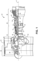
- FIG. 1 is a quarter-sectional view that schematically illustrates example gas turbine engine 20 that includes fan section 22, compressor section 24, combustor section 26 and turbine section 28.
- Alternative engines might include an augmenter section (not shown) among other systems or features.
- Fan section 22 drives air along bypass flow path B while compressor section 24 draws air in along core flow path C where air is compressed and communicated to combustor section 26.
- combustor section 26 air is mixed with fuel and ignited to generate a high pressure exhaust gas stream that expands through turbine section 28 where energy is extracted and utilized to drive fan section 22 and compressor section 24.
- turbofan gas turbine engine depicts a turbofan gas turbine engine
- concepts described herein are not limited to use with turbofans as the teachings may be applied to other types of turbine engines; for example, an industrial gas turbine; a reverse-flow gas turbine engine; and a turbine engine including a three-spool architecture in which three spools concentrically rotate about a common axis and where a low spool enables a low pressure turbine to drive a fan via a gearbox, an intermediate spool that enables an intermediate pressure turbine to drive a first compressor of the compressor section, and a high spool that enables a high pressure turbine to drive a high pressure compressor of the compressor section.
- the example gas turbine engine 20 generally includes low speed spool 30 and high speed spool 32 mounted for rotation about center axis A of gas turbine engine 20 relative to engine static structure 36 via several bearing systems 38. It should be understood that various bearing systems 38 at various locations may alternatively or additionally be provided.
- Low speed spool 30 generally includes inner shaft 40 that connects fan 42 and low pressure (or first) compressor section 44 to low pressure (or first) turbine section 46.
- Inner shaft 40 drives fan 42 through a speed change device, such as geared architecture 48, to drive fan 42 at a lower speed than low speed spool 30.
- High-speed spool 32 includes outer shaft 50 that interconnects high pressure (or second) compressor section 52 and high pressure (or second) turbine section 54.
- Inner shaft 40 and outer shaft 50 are concentric and rotate via bearing systems 38 about center axis A.
- Combustor 56 is arranged between high pressure compressor 52 and high pressure turbine 54.
- high pressure turbine 54 includes at least two stages to provide double stage high pressure turbine 54.
- high pressure turbine 54 includes only a single stage.
- a "high pressure" compressor or turbine experiences a higher pressure than a corresponding "low pressure” compressor or turbine.
- the example low pressure turbine 46 has a pressure ratio that is greater than about 5.
- the pressure ratio of the example low pressure turbine 46 is measured prior to an inlet of low pressure turbine 46 as related to the pressure measured at the outlet of low pressure turbine 46 prior to an exhaust nozzle.
- Mid-turbine frame 58 of engine static structure 36 can be arranged generally between high pressure turbine 54 and low pressure turbine 46.
- Mid-turbine frame 58 further supports bearing systems 38 in turbine section 28 as well as setting airflow entering the low pressure turbine 46.
- the core airflow C is compressed first by low pressure compressor 44 and then by high pressure compressor 52 mixed with fuel and ignited in combustor 56 to produce high speed exhaust gases that are then expanded through high pressure turbine 54 and low pressure turbine 46.
- Mid-turbine frame 58 includes vanes 59, which are in the core airflow path and function as an inlet guide vane for low pressure turbine 46. Utilizing vanes 59 of mid-turbine frame 58 as the inlet guide vanes for low pressure turbine 46 decreases the axial length of the low pressure turbine 46 without increasing the axial length of mid-turbine frame 58. Reducing or eliminating the number of vanes in low pressure turbine 46 shortens the axial length of turbine section 28. Thus, the compactness of gas turbine engine 20 is increased and a higher power density may be achieved.
- the disclosed gas turbine engine 20 in one example is a high-bypass geared aircraft engine.
- gas turbine engine 20 includes a bypass ratio greater than about six (6), with an example embodiment being greater than about ten (10).
- the example geared architecture 48 is an epicyclical gear train, such as a planetary gear system, star gear system or other known gear system, with a gear reduction ratio of greater than about 2.3.
- gas turbine engine 20 includes a bypass ratio greater than about ten (10:1) and the fan diameter is significantly larger than an outer diameter of low pressure compressor 44. It should be understood, however, that the above parameters are only exemplary of one embodiment of a gas turbine engine including a geared architecture and that the present disclosure is applicable to other gas turbine engines.
- a low spool generally connects a low pressure compressor and a low pressure turbine
- a high spool generally connects a high pressure compressor and a high pressure turbine. Most often the high spool rotates faster than the low spool.
- Differential gear assembly 60 can be modified and relocated as needed to offtake power from a turbine assembly having any two concentric counter-rotating shafts / spools such as high and intermediate, intermediate and low, and likely, high and low
- FIG. 2 shows details of a first example embodiment of differential gear assembly 60 providing power to accessory system 62 from both low spool 30 and high spool 32.
- low spool 30 includes low spool accessory drive gear 70 driven by low rotor shaft 40
- high spool 32 includes high spool accessory drive gear 74 driven by high rotor shaft 50 concentric around at least a portion of low rotor shaft 40.
- differential gear assembly 60 As noted above, these embodiments of a differential gear assembly (60 in FIG. 2 ) are designed around a counter-rotating shaft configuration. That is, low spool 30 rotates clockwise and high spool 32 rotates counter-clockwise or vice versa.
- Differential gear assembly 60 is adapted to offtake power from rotation of one or both of low spool 30 and high spool 32, and includes one or more idler gears 78. Each includes a plurality of teeth 80 meshed with low spool accessory drive gear 70 and high spool accessory drive gear 74.
- Bearing surface 81 supports idler bearing assembly 82, which in turn connects idler gear(s) 78 with differential bullgear 84.
- Differential bull gear 84 includes a plurality of differential gear teeth 86 and a corresponding at least differential bearing surface 88 engaging with idler bearing surface 81 of each of the one or more idler gears 78.
- the plurality of differential gear teeth 86 are adapted to mesh with accessory drive system 62 to transfer the power offtakes from each spool and drive one or more accessory loads 89. This may be via an accessory drive shaft, such as but not limited to towershaft 64, or another configuration depending on the particular engine architecture.
- accessory drive gears 70, 74 have heretofore been described generally.
- low spool accessory drive gear 70 includes at least a ring gear assembly
- high spool accessory drive gear 74 includes a standard bull gear.
- FIG. 3 will show an embodiment where these elements are reversed, and the configuration changes necessary to the differential gear assembly will be described accordingly.
- ring gear assembly generally includes ring gear 90 supported to low rotor shaft 40 by a plurality of ring gear bearings 94, and pinion gear 96 meshed with ring gear 90.
- Pinion gear 96 includes a fixed central portion 98 mounted to a fixed surface of the engine shown in FIG. 1 .
- Outer rotatable portion 99 of pinion gear 96 is rotatable about fixed central portion 98 to facilitate transfer between ring gear 90 and differential assembly 60.
- outer portion 98 meshes with ring gear 90 and low rotor shaft 40 (or high rotor shaft 50 as in FIG. 3 ) to drive rotation of ring gear 90 about the low rotor shaft.
- the differential bullgear (84 in FIG.
- the example embodiment can be adapted in another way such that both the differential bullgear and ring gear are "free spinning" relative to any of the shafts or spools.
- One non-limiting alternative includes supporting one or both of these gears to fixed part of the engine such as the case, while still allowing for different rotational speeds relative to one or more shafts.
- a size of differential bullgear 84 and a gear ratio of differential bullgear 84 relative to towershaft 64 are selected to selectively offtake a first portion of power from the low spool and a second portion of power from the high spool to drive a plurality of accessories (loads 89) connected to the towershaft.
- selective offtake of first and second portions of power continuously maintain a minimum excess power margin on each of low and high spools 30, 32.
- Selective offtake from each spool 30, 32 can depend at least in part on instantaneous accessory load and on relative engine speed.
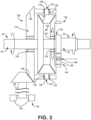
- FIG. 3 shows details of a second example embodiment of differential gear assembly 120 providing power to accessory system 62 from both counter-rotating low spool 30 and high spool 32.
- low spool 30 includes low spool accessory drive gear 122 driven by low rotor shaft 40
- high spool 32 includes high spool accessory drive gear 124 driven by high rotor shaft 50 concentric around at least a portion of low rotor shaft 40.
- Differential gear assembly 120 is adapted to offtake power from rotation of one or both of low spool 30 and high spool 32, and includes one or more idler gears 128. Each includes a plurality of teeth 126 meshed with low spool accessory drive gear 122 and high spool accessory drive gear 124. Bearing surface 130 supports idler bearing assembly 132, which in turn connects idler gear(s) 128 with differential bullgear 134.
- differential bullgear 134 includes a plurality of differential gear teeth 136 and a corresponding at least one differential bearing surface 138 engaging with idler bearing surface 130 of each of the one or more idler gears 128.
- the plurality of differential gear teeth 136 are adapted to mesh with accessory drive system 62 to transfer the power offtakes from each spool and drive one or more accessory loads 139. This may be via an accessory drive shaft, such as but not limited to towershaft 64, or another configuration depending on the particular engine architecture.
- low spool accessory drive gear 70 includes at least a ring gear assembly
- high spool accessory drive gear 74 includes a standard bull gear
- FIG. 3 shows an embodiment where these elements are reversed, namely, low spool accessory drive gear 122 includes at least a standard bull gear, while high spool accessory drive gear 124 includes at least a ring gear assembly.
- the ring gear assembly generally includes ring gear 140 supported to low rotor shaft 40 by a plurality of ring gear bearings 142, and pinion gear 144 meshed with ring gear 140.
- Pinion gear 144 includes a fixed central portion 148 mounted to a fixed surface of the engine shown in FIG. 1 .
- Outer rotatable portion 146 of pinion gear 144 is rotatable about fixed central portion 148 to facilitate transfer between ring gear 140 and differential assembly 120.
- outer portion 146 meshes with ring gear 140 and high rotor shaft 50 to drive rotation of ring gear 140 about low rotor shaft 40.
- the differential bullgear (84 in FIG. 2 , 134 in FIG.
- the example embodiment in FIG. 3 is supported to low rotor shaft 40 by another plurality of bearings 150. Similar to the example embodiment of FIG. 2 , the example embodiment in FIG. 3 can be adapted in another way such that both the differential bullgear and ring gear are "free spinning" relative to any of the shafts or spools. One non-limiting alternative includes supporting one or both of these gears to fixed part of the engine such as the case, while still allowing for different rotational speeds relative to one or more shafts.
- a size of differential bullgear 134 and a gear ratio of differential bullgear 134 relative to towershaft 64 are selected to selectively offtake a first portion of power from low spool 30 and a second portion of power from high spool 32 to drive accessories / loads 139 connected to towershaft .
- selective offtake of first and second portions of power continuously maintain a minimum excess power margin on each of low and high spools 30, 32.
- Selective offtake from each spool 30, 32 can depend at least in part on instantaneous accessory load and on relative engine speed.
- Additional power may be taken from the low spool at higher engine speeds or during acceleration, but (a) this does not always exceed the amount of power taken from the high spool, and (b) other parameters and load demands will always affect the instantaneous and total distribution of power offtake between the low and high spools during any given flight cycle.
- An example embodiment of a turbine engine assembly includes a low spool including a low spool accessory drive gear driven by a low rotor shaft, a high spool including a high spool accessory drive gear driven by a high rotor shaft concentric around a portion of the low rotor shaft, and a differential gear assembly adapted to offtake power from rotation of one or both of the low spool and the high spool to drive one or more accessory loads.
- the differential gear assembly includes a differential bullgear and one or more idler gears each including a plurality of teeth meshed with the low spool accessory drive gear and the high spool accessory drive gear, and a bearing surface.
- the differential bull gear includes a plurality of teeth and a corresponding at least one bearing surface engaging with the bearing surface of each of the one or more idler gears.
- the plurality of teeth are adapted to mesh with an accessory drive system to transfer the power offtake and drive the one or more accessory loads.
- the assembly of the preceding paragraph can optionally include any one or more of the following features, configurations and/or additional components:
- the ring gear assembly includes a ring gear supported to the low rotor shaft by a first plurality of bearings; and a pinion gear meshed with the ring gear.
- a further example of any of the foregoing assemblies further comprising an accessory drive shaft as part of the accessory drive system.
- accessory drive shaft comprises a towershaft.
- a further example of any of the foregoing assemblies wherein a size of the differential bullgear and a gear ratio of the differential bullgear, relative to the towershaft, are selected to selectively offtake a first portion of power from the low spool and a second portion of power from the high spool to drive a plurality of accessories connected to the towershaft.
- An embodiment of a differential gear assembly for a pair of counter rotating concentric drive shafts includes a first idler gear and a differential bull gear.
- the first idler gear includes a plurality of idler teeth adapted to mesh with a first accessory drive gear connected to a first of the concentric drive shafts.
- the differential bull gear includes a plurality of differential teeth and a corresponding at least one bearing surface engaging with a bearing surface of at least the first idler gears.
- the plurality of differential teeth adapted to mesh with an accessory drive system to transfer a first power offtake from the first of the concentric drive shafts and a second power offtake from a second of the concentric drive shafts to drive one or more accessory loads.
- a further example of the foregoing assembly further comprising a ring gear assembly comprising a ring gear supported to the first or second of the concentric drive shaft via a first plurality of bearings; and a pinion gear meshed with the ring gear, the pinion gear including a fixed central portion of the pinion gear mounted to a fixed surface of the engine, and an outer portion of the pinion gear rotatable about the fixed central portion.
- a further example of any of the foregoing assemblies further comprising an accessory drive system, including a towershaft and a plurality of accessories connected thereto.
- a further example of any of the foregoing assemblies wherein a size of the differential bullgear and a gear ratio of the differential bullgear, relative to the towershaft, are selected to selectively offtake a first portion of power to continuously maintain a minimum excess power margin on each of the first and second spools.
Landscapes
- Engineering & Computer Science (AREA)
- Chemical & Material Sciences (AREA)
- Combustion & Propulsion (AREA)
- Mechanical Engineering (AREA)
- General Engineering & Computer Science (AREA)
- Retarders (AREA)
- Gear Transmission (AREA)
Abstract
Description
- The disclosure relates generally to turbine engines and more specifically to driving accessories of a turbine engine.
- Additional demands on large military and commercial engines solely utilize the high spool rotor to extract horsepower and power accessories including fuel/oil pumps, PMAG, and aircraft accessory pumps. With increasing demand for horsepower extraction to power additional accessories and provide more electrical power, extraction limits of the high rotor are being reached and there is a need for additional horsepower. At the very least, it would be useful to better balance the extraction demands between more than one spool.
- However, the "penalties" for current modes of extracting power from more than one spool at a time, add complexity, weight, cost, and maintainability that present challenges to utilizing a second lower spool.
- In accordance with a first aspect of the disclosure, a turbine engine assembly includes a low spool including a low spool accessory drive gear driven by a low rotor shaft, a high spool including a high spool accessory drive gear driven by a high rotor shaft concentric around a portion of the low rotor shaft, and a differential gear assembly adapted to offtake power from rotation of one or both of the low spool and the high spool to drive one or more accessory loads. The differential gear assembly includes a differential bullgear and one or more idler gears each including a plurality of teeth meshed with the low spool accessory drive gear and the high spool accessory drive gear, and a bearing surface. The differential bull gear includes a plurality of teeth and a corresponding at least one bearing surface engaging with the bearing surface of each of the one or more idler gears. The plurality of teeth are adapted to mesh with an accessory drive system to transfer the power offtake and drive the one or more accessory loads.
- Optionally, and in accordance with the above, the low spool accessory drive gear comprises one of a ring gear assembly and a bull gear.
- Optionally, and in accordance with any of the above, the high spool accessory drive gear comprises the other of the ring gear assembly and the bull gear
- Optionally, and in accordance with any of the above, the ring gear assembly includes a ring gear supported to the low rotor shaft by a first plurality of bearings and a pinion gear meshed with the ring gear.
- Optionally, and in accordance with any of the above, a fixed central portion of the pinion gear is mounted to a fixed surface of the engine.
- Optionally, and in accordance with any of the above, an outer portion of the pinion gear is rotatable about the fixed central portion.
- Optionally, and in accordance with any of the above, the outer portion meshes with the ring gear and the low rotor shaft or the high rotor shaft to drive rotation of the ring gear about the low rotor shaft.
- Optionally, and in accordance with any of the above, the differential bullgear is supported to the low rotor shaft by a second plurality of bearings.
- Optionally, and in accordance with any of the above, the low rotor shaft rotates in a first direction and the high rotor shaft rotates in a second direction opposite the first direction.
- Optionally, and in accordance with any of the above, the assembly further comprises an accessory drive shaft as part of the accessory drive system.
- Optionally, and in accordance with any of the above, the accessory drive shaft comprises a towershaft.
- Optionally, and in accordance with any of the above, a size of the differential bullgear and a gear ratio of the differential bullgear, relative to the towershaft, are selected to selectively offtake a first portion of power from the low spool and a second portion of power from the high spool to drive a plurality of accessories connected to the towershaft.
- Optionally, and in accordance with any of the above, the selective offtake of first and second portions of power continuously maintain a minimum excess power margin on each of the low and high spools.
- Optionally, and in accordance with any of the above, the selective offtake depends at least in part on instantaneous accessory load and on relative engine speed.
- In accordance with a second aspect of the present disclosure, a differential gear assembly for a pair of counter rotating concentric drive shafts includes a first idler gear and a differential bull gear. The first idler gear includes a plurality of idler teeth adapted to mesh with a first accessory drive gear connected to a first of the concentric drive shafts. The differential bull gear includes a plurality of differential teeth and a corresponding at least one bearing surface engaging with a bearing surface of at least the first idler gears. The plurality of differential teeth adapted to mesh with an accessory drive system to transfer a first power offtake from the first of the concentric drive shafts and a second power offtake from a second of the concentric drive shafts to drive one or more accessory loads.
-
-
FIG. 1 is a schematic quarter-section of a gas turbine engine. -
FIG. 2 shows a first example embodiment of a differential gear assembly incorporated with a low and high spool. -
FIG. 3 shows a second example embodiment of a differential gear assembly incorporated with a low and high spool. -
FIG. 1 is a quarter-sectional view that schematically illustrates examplegas turbine engine 20 that includesfan section 22,compressor section 24, combustor section 26 andturbine section 28. Alternative engines might include an augmenter section (not shown) among other systems or features.Fan section 22 drives air along bypass flow path B whilecompressor section 24 draws air in along core flow path C where air is compressed and communicated to combustor section 26. In combustor section 26, air is mixed with fuel and ignited to generate a high pressure exhaust gas stream that expands throughturbine section 28 where energy is extracted and utilized to drivefan section 22 andcompressor section 24. - Although the disclosed non-limiting embodiment depicts a turbofan gas turbine engine, it should be understood that the concepts described herein are not limited to use with turbofans as the teachings may be applied to other types of turbine engines; for example, an industrial gas turbine; a reverse-flow gas turbine engine; and a turbine engine including a three-spool architecture in which three spools concentrically rotate about a common axis and where a low spool enables a low pressure turbine to drive a fan via a gearbox, an intermediate spool that enables an intermediate pressure turbine to drive a first compressor of the compressor section, and a high spool that enables a high pressure turbine to drive a high pressure compressor of the compressor section.
- The example
gas turbine engine 20 generally includeslow speed spool 30 andhigh speed spool 32 mounted for rotation about center axis A ofgas turbine engine 20 relative to enginestatic structure 36 viaseveral bearing systems 38. It should be understood thatvarious bearing systems 38 at various locations may alternatively or additionally be provided. -
Low speed spool 30 generally includesinner shaft 40 that connectsfan 42 and low pressure (or first)compressor section 44 to low pressure (or first)turbine section 46.Inner shaft 40 drivesfan 42 through a speed change device, such as gearedarchitecture 48, to drivefan 42 at a lower speed thanlow speed spool 30. High-speed spool 32 includesouter shaft 50 that interconnects high pressure (or second)compressor section 52 and high pressure (or second)turbine section 54.Inner shaft 40 andouter shaft 50 are concentric and rotate viabearing systems 38 about center axis A. - Combustor 56 is arranged between
high pressure compressor 52 andhigh pressure turbine 54. In one example,high pressure turbine 54 includes at least two stages to provide double stagehigh pressure turbine 54. In another example,high pressure turbine 54 includes only a single stage. As used herein, a "high pressure" compressor or turbine experiences a higher pressure than a corresponding "low pressure" compressor or turbine. - The example
low pressure turbine 46 has a pressure ratio that is greater than about 5. The pressure ratio of the examplelow pressure turbine 46 is measured prior to an inlet oflow pressure turbine 46 as related to the pressure measured at the outlet oflow pressure turbine 46 prior to an exhaust nozzle. -
Mid-turbine frame 58 of enginestatic structure 36 can be arranged generally betweenhigh pressure turbine 54 andlow pressure turbine 46.Mid-turbine frame 58 further supports bearingsystems 38 inturbine section 28 as well as setting airflow entering thelow pressure turbine 46. - The core airflow C is compressed first by
low pressure compressor 44 and then byhigh pressure compressor 52 mixed with fuel and ignited incombustor 56 to produce high speed exhaust gases that are then expanded throughhigh pressure turbine 54 andlow pressure turbine 46.Mid-turbine frame 58 includesvanes 59, which are in the core airflow path and function as an inlet guide vane forlow pressure turbine 46. Utilizingvanes 59 ofmid-turbine frame 58 as the inlet guide vanes forlow pressure turbine 46 decreases the axial length of thelow pressure turbine 46 without increasing the axial length ofmid-turbine frame 58. Reducing or eliminating the number of vanes inlow pressure turbine 46 shortens the axial length ofturbine section 28. Thus, the compactness ofgas turbine engine 20 is increased and a higher power density may be achieved. - The disclosed
gas turbine engine 20 in one example is a high-bypass geared aircraft engine. In a further example,gas turbine engine 20 includes a bypass ratio greater than about six (6), with an example embodiment being greater than about ten (10). The example gearedarchitecture 48 is an epicyclical gear train, such as a planetary gear system, star gear system or other known gear system, with a gear reduction ratio of greater than about 2.3. - In one disclosed embodiment,
gas turbine engine 20 includes a bypass ratio greater than about ten (10:1) and the fan diameter is significantly larger than an outer diameter oflow pressure compressor 44. It should be understood, however, that the above parameters are only exemplary of one embodiment of a gas turbine engine including a geared architecture and that the present disclosure is applicable to other gas turbine engines. - It will be recognized that the terms high and low, unless described in another way, are relative. For example, a low spool generally connects a low pressure compressor and a low pressure turbine, while a high spool generally connects a high pressure compressor and a high pressure turbine. Most often the high spool rotates faster than the low spool. Further, though shown as a two-spool engine, it will be appreciated by the skilled artisan that the teachings can be readily adapted to other engine configurations, such as a three-spool engine.
Differential gear assembly 60 can be modified and relocated as needed to offtake power from a turbine assembly having any two concentric counter-rotating shafts / spools such as high and intermediate, intermediate and low, and likely, high and low -
FIG. 2 shows details of a first example embodiment ofdifferential gear assembly 60 providing power toaccessory system 62 from bothlow spool 30 andhigh spool 32. As noted with respect toFIG. 1 ,low spool 30 includes low spoolaccessory drive gear 70 driven bylow rotor shaft 40, whilehigh spool 32 includes high spoolaccessory drive gear 74 driven byhigh rotor shaft 50 concentric around at least a portion oflow rotor shaft 40. - As noted above, these embodiments of a differential gear assembly (60 in
FIG. 2 ) are designed around a counter-rotating shaft configuration. That is,low spool 30 rotates clockwise andhigh spool 32 rotates counter-clockwise or vice versa.Differential gear assembly 60 is adapted to offtake power from rotation of one or both oflow spool 30 andhigh spool 32, and includes one or more idler gears 78. Each includes a plurality ofteeth 80 meshed with low spoolaccessory drive gear 70 and high spoolaccessory drive gear 74. Bearingsurface 81 supportsidler bearing assembly 82, which in turn connects idler gear(s) 78 withdifferential bullgear 84. -
Differential bull gear 84 includes a plurality ofdifferential gear teeth 86 and a corresponding at least differential bearingsurface 88 engaging withidler bearing surface 81 of each of the one or more idler gears 78. The plurality ofdifferential gear teeth 86 are adapted to mesh withaccessory drive system 62 to transfer the power offtakes from each spool and drive one or more accessory loads 89. This may be via an accessory drive shaft, such as but not limited totowershaft 64, or another configuration depending on the particular engine architecture. - Note that accessory drive gears 70, 74 have heretofore been described generally. In the example embodiment of
FIG. 2 , low spoolaccessory drive gear 70 includes at least a ring gear assembly, while high spoolaccessory drive gear 74 includes a standard bull gear.FIG. 3 will show an embodiment where these elements are reversed, and the configuration changes necessary to the differential gear assembly will be described accordingly. - In both cases, ring gear assembly generally includes
ring gear 90 supported tolow rotor shaft 40 by a plurality ofring gear bearings 94, andpinion gear 96 meshed withring gear 90.Pinion gear 96 includes a fixedcentral portion 98 mounted to a fixed surface of the engine shown inFIG. 1 . Outerrotatable portion 99 ofpinion gear 96 is rotatable about fixedcentral portion 98 to facilitate transfer betweenring gear 90 anddifferential assembly 60. Here,outer portion 98 meshes withring gear 90 and low rotor shaft 40 (orhigh rotor shaft 50 as inFIG. 3 ) to drive rotation ofring gear 90 about the low rotor shaft. Also in both example embodiments, the differential bullgear (84 inFIG. 2 ) is shown to be supported tolow rotor shaft 40 by another plurality ofbearings 102. Alternatively, in bothFIG. 2 andFIG. 3 , the example embodiment can be adapted in another way such that both the differential bullgear and ring gear are "free spinning" relative to any of the shafts or spools. One non-limiting alternative includes supporting one or both of these gears to fixed part of the engine such as the case, while still allowing for different rotational speeds relative to one or more shafts. - A size of
differential bullgear 84 and a gear ratio ofdifferential bullgear 84 relative totowershaft 64, are selected to selectively offtake a first portion of power from the low spool and a second portion of power from the high spool to drive a plurality of accessories (loads 89) connected to the towershaft. Preferably, selective offtake of first and second portions of power continuously maintain a minimum excess power margin on each of low andhigh spools spool -
FIG. 3 shows details of a second example embodiment ofdifferential gear assembly 120 providing power toaccessory system 62 from both counter-rotatinglow spool 30 andhigh spool 32. As withFIGS. 1 and2 ,low spool 30 includes low spoolaccessory drive gear 122 driven bylow rotor shaft 40, whilehigh spool 32 includes high spoolaccessory drive gear 124 driven byhigh rotor shaft 50 concentric around at least a portion oflow rotor shaft 40. -
Differential gear assembly 120 is adapted to offtake power from rotation of one or both oflow spool 30 andhigh spool 32, and includes one or more idler gears 128. Each includes a plurality ofteeth 126 meshed with low spoolaccessory drive gear 122 and high spoolaccessory drive gear 124.Bearing surface 130 supportsidler bearing assembly 132, which in turn connects idler gear(s) 128 withdifferential bullgear 134. - Similar to
FIG. 2 ,differential bullgear 134 includes a plurality ofdifferential gear teeth 136 and a corresponding at least onedifferential bearing surface 138 engaging withidler bearing surface 130 of each of the one or more idler gears 128. The plurality ofdifferential gear teeth 136 are adapted to mesh withaccessory drive system 62 to transfer the power offtakes from each spool and drive one or more accessory loads 139. This may be via an accessory drive shaft, such as but not limited totowershaft 64, or another configuration depending on the particular engine architecture. - Note that in the example embodiment of
FIG. 2 , low spoolaccessory drive gear 70 includes at least a ring gear assembly, while high spoolaccessory drive gear 74 includes a standard bull gear.FIG. 3 shows an embodiment where these elements are reversed, namely, low spoolaccessory drive gear 122 includes at least a standard bull gear, while high spoolaccessory drive gear 124 includes at least a ring gear assembly. - In both cases, the ring gear assembly generally includes
ring gear 140 supported tolow rotor shaft 40 by a plurality ofring gear bearings 142, andpinion gear 144 meshed withring gear 140.Pinion gear 144 includes a fixedcentral portion 148 mounted to a fixed surface of the engine shown inFIG. 1 . Outerrotatable portion 146 ofpinion gear 144 is rotatable about fixedcentral portion 148 to facilitate transfer betweenring gear 140 anddifferential assembly 120. Here,outer portion 146 meshes withring gear 140 andhigh rotor shaft 50 to drive rotation ofring gear 140 aboutlow rotor shaft 40. Also in both example embodiments, the differential bullgear (84 inFIG. 2 , 134 inFIG. 3 ) is supported tolow rotor shaft 40 by another plurality ofbearings 150. Similar to the example embodiment ofFIG. 2 , the example embodiment inFIG. 3 can be adapted in another way such that both the differential bullgear and ring gear are "free spinning" relative to any of the shafts or spools. One non-limiting alternative includes supporting one or both of these gears to fixed part of the engine such as the case, while still allowing for different rotational speeds relative to one or more shafts. - A size of
differential bullgear 134 and a gear ratio ofdifferential bullgear 134 relative totowershaft 64, are selected to selectively offtake a first portion of power fromlow spool 30 and a second portion of power fromhigh spool 32 to drive accessories / loads 139 connected to towershaft . Preferably, selective offtake of first and second portions of power continuously maintain a minimum excess power margin on each of low andhigh spools spool - It will be recognized that the "first" and "second" portions of power referenced in the preceding paragraph, and throughout the instant document merely are used to allow the reader to differentiate between the "first" power offtake from the low spool and the "second" power offtake from the high spool. Absent any explicit statement to the contrary, the "first" portion of power offtake is not necessarily greater than, equal to, or less than the "second" portion of power offtake at any given time or operational condition. Generally, but not exclusively, more power will be taken from the high spool during low engine speeds. Additional power may be taken from the low spool at higher engine speeds or during acceleration, but (a) this does not always exceed the amount of power taken from the high spool, and (b) other parameters and load demands will always affect the instantaneous and total distribution of power offtake between the low and high spools during any given flight cycle.
- The following are non-exclusive embodiments of the present disclosure.
- An example embodiment of a turbine engine assembly includes a low spool including a low spool accessory drive gear driven by a low rotor shaft, a high spool including a high spool accessory drive gear driven by a high rotor shaft concentric around a portion of the low rotor shaft, and a differential gear assembly adapted to offtake power from rotation of one or both of the low spool and the high spool to drive one or more accessory loads. The differential gear assembly includes a differential bullgear and one or more idler gears each including a plurality of teeth meshed with the low spool accessory drive gear and the high spool accessory drive gear, and a bearing surface. The differential bull gear includes a plurality of teeth and a corresponding at least one bearing surface engaging with the bearing surface of each of the one or more idler gears. The plurality of teeth are adapted to mesh with an accessory drive system to transfer the power offtake and drive the one or more accessory loads.
- The assembly of the preceding paragraph can optionally include any one or more of the following features, configurations and/or additional components:
A further example of the foregoing assembly, wherein the low spool accessory drive gear comprises one of a ring gear assembly and a bull gear. - A further example of any of the foregoing assemblies, wherein the high spool accessory drive gear comprises the other of the ring gear assembly and the bull gear.
- A further example of any of the foregoing assemblies, wherein the ring gear assembly includes a ring gear supported to the low rotor shaft by a first plurality of bearings; and a pinion gear meshed with the ring gear.
- A further example of any of the foregoing assemblies, wherein a fixed central portion of the pinion gear is mounted to a fixed surface of the engine.
- A further example of any of the foregoing assemblies, wherein an outer portion of the pinion gear is rotatable about the fixed central portion.
- A further example of any of the foregoing assemblies, wherein the outer portion meshes with the ring gear and the low rotor shaft or the high rotor shaft to drive rotation of the ring gear about the low rotor shaft.
- A further example of any of the foregoing assemblies, wherein the differential bullgear is supported to the low rotor shaft by a second plurality of bearings.
- A further example of any of the foregoing assemblies, wherein the low rotor shaft rotates in a first direction and the high rotor shaft rotates in a second direction opposite the first direction.
- A further example of any of the foregoing assemblies, further comprising an accessory drive shaft as part of the accessory drive system.
- A further example of any of the foregoing assemblies, wherein the accessory drive shaft comprises a towershaft.
- A further example of any of the foregoing assemblies, wherein a size of the differential bullgear and a gear ratio of the differential bullgear, relative to the towershaft, are selected to selectively offtake a first portion of power from the low spool and a second portion of power from the high spool to drive a plurality of accessories connected to the towershaft.
- A further example of any of the foregoing assemblies, wherein the selective offtake of first and second portions of power continuously maintain a minimum excess power margin on each of the low and high spools.
- A further example of any of the foregoing assemblies, wherein the selective offtake depends at least in part on instantaneous accessory load and on relative engine speed.
- An embodiment of a differential gear assembly for a pair of counter rotating concentric drive shafts includes a first idler gear and a differential bull gear. The first idler gear includes a plurality of idler teeth adapted to mesh with a first accessory drive gear connected to a first of the concentric drive shafts. The differential bull gear includes a plurality of differential teeth and a corresponding at least one bearing surface engaging with a bearing surface of at least the first idler gears. The plurality of differential teeth adapted to mesh with an accessory drive system to transfer a first power offtake from the first of the concentric drive shafts and a second power offtake from a second of the concentric drive shafts to drive one or more accessory loads.
- The assembly of the preceding paragraph can optionally include any one or more of the following features, configurations and/or additional components:
A further example of the foregoing assembly, further comprising a ring gear assembly comprising a ring gear supported to the first or second of the concentric drive shaft via a first plurality of bearings; and a pinion gear meshed with the ring gear, the pinion gear including a fixed central portion of the pinion gear mounted to a fixed surface of the engine, and an outer portion of the pinion gear rotatable about the fixed central portion. - A further example of any of the foregoing assemblies, wherein the outer portion meshes with the ring gear and the first or second of the concentric drive shafts to drive rotation of the ring gear thereabout.
- A further example of any of the foregoing assemblies, wherein the differential bullgear is supported to the first or second drive shaft by a second plurality of bearings.
- A further example of any of the foregoing assemblies, further comprising an accessory drive system, including a towershaft and a plurality of accessories connected thereto.
- A further example of any of the foregoing assemblies, wherein a size of the differential bullgear and a gear ratio of the differential bullgear, relative to the towershaft, are selected to selectively offtake a first portion of power to continuously maintain a minimum excess power margin on each of the first and second spools.
- While the invention has been described with reference to an exemplary embodiment(s), it will be understood by those skilled in the art that various changes may be made and equivalents may be substituted for elements thereof without departing from the scope of the invention. In addition, many modifications may be made to adapt a particular situation or material to the teachings of the invention without departing from the essential scope thereof. Therefore, it is intended that the invention not be limited to the particular embodiment(s) disclosed, but that the invention will include all embodiments falling within the scope of the appended claims.
Claims (6)
- A differential gear assembly (60, 120) for a pair of counter rotating concentric drive shafts (40, 50), the differential gear assembly (60, 120) comprising:a first idler gear (78, 128) including a plurality of idler teeth (80, 126) adapted to mesh with a first accessory drive gear (70, 122) connected to a first of the concentric drive shafts (40); anda differential bull gear (84, 134) including a plurality of differential teeth (86, 136) and a corresponding at least one bearing surface (88, 138) engaging with a bearing surface (81, 130) of at least the first idler gears (78, 128), the plurality of differential teeth (86, 136) adapted to mesh with an accessory drive system (62) to transfer a first power offtake from the first of the concentric drive shafts (40) and a second power offtake from a second of the concentric drive shafts (50) to drive one or more accessory loads (89, 139).
- The assembly of claim 1, further comprising a ring gear assembly comprising:a ring gear (90, 140) supported to the first or second of the concentric drive shafts (40, 50) via a first plurality of bearings (94, 142); anda pinion gear (96, 144) meshed with the ring gear (90, 140), the pinion gear (96, 144) including a fixed central portion (98, 148) of the pinion gear (96, 144) mounted to a fixed surface of the engine (20), and an outer portion (99, 146) of the pinion gear (96, 144) rotatable about the fixed central portion (98, 148).
- The assembly of claim 2, wherein the outer portion (99, 146) meshes with the ring gear (90, 140) and the first or second of the concentric drive shafts (40, 50) to drive rotation of the ring gear (90, 140) thereabout.
- The assembly of any preceding claim, wherein the differential bull gear (84, 134) is supported to the first or second drive shaft (40, 50) by a second plurality of bearings (102, 150).
- The assembly of any of any preceding claim, further comprising an accessory drive system (62), including a towershaft (64) and a plurality of accessories (89, 139) connected thereto.
- The assembly of claim 5, wherein a size of the differential bull gear (84, 134) and a gear ratio of the differential bull gear (84, 134), relative to the towershaft (64), are selected to selectively offtake a first portion of power to continuously maintain a minimum excess power margin on each of the first and second drive shafts (40, 50).
Applications Claiming Priority (2)
| Application Number | Priority Date | Filing Date | Title |
|---|---|---|---|
| US201962842186P | 2019-05-02 | 2019-05-02 | |
| EP20160221.6A EP3734046B1 (en) | 2019-05-02 | 2020-02-28 | High and low spool differential gear assembly |
Related Parent Applications (1)
| Application Number | Title | Priority Date | Filing Date |
|---|---|---|---|
| EP20160221.6A Division EP3734046B1 (en) | 2019-05-02 | 2020-02-28 | High and low spool differential gear assembly |
Publications (2)
| Publication Number | Publication Date |
|---|---|
| EP4481182A2 true EP4481182A2 (en) | 2024-12-25 |
| EP4481182A3 EP4481182A3 (en) | 2025-03-19 |
Family
ID=69743021
Family Applications (2)
| Application Number | Title | Priority Date | Filing Date |
|---|---|---|---|
| EP24212475.8A Pending EP4481182A3 (en) | 2019-05-02 | 2020-02-28 | High and low spool differential gear assembly |
| EP20160221.6A Active EP3734046B1 (en) | 2019-05-02 | 2020-02-28 | High and low spool differential gear assembly |
Family Applications After (1)
| Application Number | Title | Priority Date | Filing Date |
|---|---|---|---|
| EP20160221.6A Active EP3734046B1 (en) | 2019-05-02 | 2020-02-28 | High and low spool differential gear assembly |
Country Status (2)
| Country | Link |
|---|---|
| US (1) | US11549445B2 (en) |
| EP (2) | EP4481182A3 (en) |
Families Citing this family (2)
| Publication number | Priority date | Publication date | Assignee | Title |
|---|---|---|---|---|
| US12060834B2 (en) * | 2021-05-07 | 2024-08-13 | Rtx Corporation | Hybrid electric idle and braking for an aircraft |
| US12228075B2 (en) * | 2022-12-09 | 2025-02-18 | General Electric Company | Integral engine inlet frame air-cooled oil cooling apparatus |
Family Cites Families (10)
| Publication number | Priority date | Publication date | Assignee | Title |
|---|---|---|---|---|
| JPS63159627A (en) * | 1986-11-03 | 1988-07-02 | ゼネラル・エレクトリック・カンパニイ | Differential type power device for multiple spool type turbine engine |
| FR2863312B1 (en) * | 2003-12-09 | 2008-07-04 | Snecma Moteurs | DOUBLE-BODY TURBOREACTOR WITH MEANS FOR DRIVING ACCESSORY MACHINES |
| WO2008044973A1 (en) * | 2006-10-13 | 2008-04-17 | Volvo Aero Corporation | A device for and a method of starting a gas turbine engine |
| US7882691B2 (en) | 2007-07-05 | 2011-02-08 | Hamilton Sundstrand Corporation | High to low pressure spool summing gearbox for accessory power extraction and electric start |
| US8096913B2 (en) * | 2008-10-13 | 2012-01-17 | Traxxas Lp | Locking differential assembly for a model vehicle |
| US8814502B2 (en) | 2011-05-31 | 2014-08-26 | Pratt & Whitney Canada Corp. | Dual input drive AGB for gas turbine engines |
| US9200592B2 (en) | 2011-06-28 | 2015-12-01 | United Technologies Corporation | Mechanism for turbine engine start from low spool |
| US9347373B2 (en) * | 2013-12-19 | 2016-05-24 | Pratt & Whitney Canada Corp. | Gas turbine engine with transmission |
| US10526975B2 (en) | 2016-11-30 | 2020-01-07 | The Boeing Company | Power extraction system and method for a gas turbine engine of a vehicle |
| US20180283281A1 (en) | 2017-03-31 | 2018-10-04 | Hamilton Sundstrand Corporation | Accessory gearboxes |
-
2020
- 2020-02-28 EP EP24212475.8A patent/EP4481182A3/en active Pending
- 2020-02-28 EP EP20160221.6A patent/EP3734046B1/en active Active
- 2020-03-02 US US16/806,499 patent/US11549445B2/en active Active
Also Published As
| Publication number | Publication date |
|---|---|
| US20200378310A1 (en) | 2020-12-03 |
| EP3734046B1 (en) | 2024-11-13 |
| EP3734046A1 (en) | 2020-11-04 |
| US11549445B2 (en) | 2023-01-10 |
| EP4481182A3 (en) | 2025-03-19 |
Similar Documents
| Publication | Publication Date | Title |
|---|---|---|
| EP3101258B2 (en) | Geared architecture for a gas turbine engine and a corresponding method | |
| US8973465B2 (en) | Gearbox for gas turbine engine | |
| CA2879756C (en) | Geared fan with inner counter rotating compressor | |
| US9926850B2 (en) | Compound star gear system with rolling element bearings | |
| US9267389B2 (en) | Geared architecture carrier torque frame assembly | |
| US11162430B2 (en) | Geared gas turbine engine | |
| EP1921290A2 (en) | Turbofan engine assembly and method of assembling same | |
| EP2959129B1 (en) | Auxiliary lubricant supply pump stage integral with main lubricant pump stage | |
| US20140090386A1 (en) | Geared turbofan with fan and core mounted accessory gearboxes | |
| EP3608515A1 (en) | Flexible support structure for a geared architecture gas turbine engine | |
| EP2855874B1 (en) | Gas turbine engine with a counter rotating fan | |
| US11549445B2 (en) | High and low spool differential gear assembly | |
| EP3109451A1 (en) | Gear system for high bypass ratio geared turbofan engine | |
| EP2899389A1 (en) | Flexible support structure for a geared architecture gas turbine engine | |
| EP3048284A1 (en) | Flexible support structure for a geared architecture gas turbine engine | |
| EP3626935A1 (en) | Fan drive gear system |
Legal Events
| Date | Code | Title | Description |
|---|---|---|---|
| PUAI | Public reference made under article 153(3) epc to a published international application that has entered the european phase |
Free format text: ORIGINAL CODE: 0009012 |
|
| STAA | Information on the status of an ep patent application or granted ep patent |
Free format text: STATUS: THE APPLICATION HAS BEEN PUBLISHED |
|
| AC | Divisional application: reference to earlier application |
Ref document number: 3734046 Country of ref document: EP Kind code of ref document: P |
|
| AK | Designated contracting states |
Kind code of ref document: A2 Designated state(s): AL AT BE BG CH CY CZ DE DK EE ES FI FR GB GR HR HU IE IS IT LI LT LU LV MC MK MT NL NO PL PT RO RS SE SI SK SM TR |
|
| REG | Reference to a national code |
Ref country code: DE Ref legal event code: R079 Free format text: PREVIOUS MAIN CLASS: F02C0007360000 Ipc: F02C0007320000 |
|
| PUAL | Search report despatched |
Free format text: ORIGINAL CODE: 0009013 |
|
| AK | Designated contracting states |
Kind code of ref document: A3 Designated state(s): AL AT BE BG CH CY CZ DE DK EE ES FI FR GB GR HR HU IE IS IT LI LT LU LV MC MK MT NL NO PL PT RO RS SE SI SK SM TR |
|
| RIC1 | Information provided on ipc code assigned before grant |
Ipc: F02C 7/36 20060101ALI20250212BHEP Ipc: F02C 7/32 20060101AFI20250212BHEP |
|
| STAA | Information on the status of an ep patent application or granted ep patent |
Free format text: STATUS: REQUEST FOR EXAMINATION WAS MADE |
|
| 17P | Request for examination filed |
Effective date: 20250919 |
|
| STAA | Information on the status of an ep patent application or granted ep patent |
Free format text: STATUS: EXAMINATION IS IN PROGRESS |
|
| 17Q | First examination report despatched |
Effective date: 20260218 |